

Page 1

UR52 & UR55 User Guide
1
Preface
Thanks for choosing Ursalink UR52/UR55 industrial cellular router. The UR52/UR55 industrial cellular
router delivers tenacious connection over network with full-featured design such as automated
failover/failback, extended operating temperature, dual SIM cards, hardware watchdog, VPN, Fast
Ethernet and beyond.
This guide describes how to configure and operate the UR52/UR55 industrial cellular router. You
can refer to it for detailed functionality and router configuration.
Readers
This guide is mainly intended for the following users:
- Network Planners
- On-site technical support and maintenance personnel
- Network administrators responsible for network configuration and maintenance
© 2017 Xiamen Ursalink Technology Co., Ltd.
All rights reserved.
All information in this user guide is protected by copyright law. Whereby, no organization or individual
shall copy or reproduce the whole or part of this user guide by any means without written authorization
from Xiamen Ursalink Technology Co., Ltd.
Products Covered
This guide explains how to configure the following devices:
• Ursalink UR52 Industrial Cellular Router
• Ursalink UR55 Industrial Cellular Router
Related Documents
Document
Description
Ursalink UR52/UR55 Datasheet
Datasheet for the Ursalink UR5x series
industrial cellular router.
Ursalink UR52/UR55 Quick Start Guide
Quick Installation guide for the Ursalink UR5x
series industrial cellular router.
Declaration of Conformity
Page 2

UR52 & UR55 User Guide
2
Preface
Thanks for choosing Ursalink UR52&UR55 industrial cellular router. The UR52&UR55 industrial cellular
router delivers tenacious connection over network with full-featured design such as automated
failover/failback, extended operating temperature, dual SIM cards, hardware watchdog, VPN, Fast
Ethernet and beyond.
The biggest difference between UR52 and UR55 lies in the number of Ethernet ports.
This guide describes how to configure and operate the UR52&UR55 industrial cellular router. You
can refer to it for detailed functionality and router configuration.
Readers
This guide is mainly intended for the following users:
- Network Planners
- On-site technical support and maintenance personnel
- Network administrators responsible for network configuration and maintenance
© 2017 Xiamen Ursalink Technology Co., Ltd.
All rights reserved.
All information in this user guide is protected by copyright law. Whereby, no organization or individual
shall copy or reproduce the whole or part of this user guide by any means without written authorization
from Xiamen Ursalink Technology Co., Ltd.
Products Covered
This guide explains how to configure the following devices:
• Ursalink UR52 Industrial Cellular Router
• Ursalink UR55 Industrial Cellular Router
Related Documents
Document
Description
Ursalink UR52 Datasheet
Datasheet for the Ursalink UR52 industrial
cellular router.
Ursalink UR55 Datasheet
Datasheet for the Ursalink UR55 industrial
cellular router.
Ursalink UR52&UR55 Quick Start Guide
Quick Installation guide for the Ursalink
UR52&UR55 series industrial cellular router.
Page 3

UR52 & UR55 User Guide
3
Declaration of Conformity
UR52/UR55 is in conformity with the essential requirements and other relevant provisions of the CE, FCC,
and RoHS.
For assistance, please contact
Ursalink technical support:
Email: [email protected]
Tel.: 86-592-5023060
Fax: 86-592-5023065
Revision History
Date
Doc Version
Description
Nov. 14, 2017
V.1.0.0
Initial version
Page 4

UR52 & UR55 User Guide
4
Contents
Chapter 1 Product Introduction
...............................................................................................................................
8
1.1 Overview
.....................................................................................................................................................
8
1.2 Advantages
..................................................................................................................................................
8
1.3 Specifications
............................................................................................................................................
10
1.4 Dimensions (mm)
......................................................................................................................................
12
Chapter 2 Installation
.............................................................................................................................................
13
2.1 General Packing List
..................................................................................................................................
13
2.2 Product Overview
.....................................................................................................................................
14
2.3 LED Indicators
...........................................................................................................................................
15
2.5 PIN Definition
............................................................................................................................................
16
2.6 Reset Button
..............................................................................................................................................
16
2.7 SIM Card Installation
................................................................................................................................
17
2.8 Micro SD card Installation
........................................................................................................................
17
2.9 Antenna Installation
.................................................................................................................................
18
2.10 Mounting the Router
..............................................................................................................................
18
2.11 Connect the Router to a Computer
........................................................................................................
19
2.12 Installation of Power Supply and Protective Grounding
......................................................................
19
2.12.1 Power Supply Installation
...........................................................................................................
19
2.12.2 Protective Grounding Installation
..............................................................................................
20
Chapter 3 Access to Web GUI
.................................................................................................................................
21
3.1 PC Configuration for Web GUI Access to Router
.....................................................................................
21
3.2 Access to Web GUI of Router
...................................................................................................................
22
Chapter 4 Web Configuration
.................................................................................................................................
24
4.1 Status
.........................................................................................................................................................
24
4.1.1 Overview
........................................................................................................................................
24
4.1.2 Cellular
...........................................................................................................................................
25
4.1.3 Network
.........................................................................................................................................
26
4.1.4 WLAN (Only Applicable to Wi-Fi Version)
....................................................................................
27
4.1.5 VPN
.................................................................................................................................................
28
4.1.6 Routing Information
......................................................................................................................
30
4.1.7 Host List
..........................................................................................................................................
31
4.1.8 GPS
.................................................................................................................................................
31
4.2 Network
.....................................................................................................................................................
32
4.2.1 Interface
.........................................................................................................................................
32
4.2.1.1 Port
......................................................................................................................................
32
4.2.1.2 WAN
....................................................................................................................................
33
4.2.1.3 LAN
......................................................................................................................................
36
4.2.1.4 VLAN Trunk
.........................................................................................................................
37
4.2.1.5 WLAN (Only Applicable to Wi-Fi Version)
.........................................................................
39
4.2.1.6 Cellular
................................................................................................................................
40
4.2.1.7 Loopback
.............................................................................................................................
44
4.2.2 Firewall
...........................................................................................................................................
45
Page 5

UR52 & UR55 User Guide
5
4.2.2.1 ACL
.......................................................................................................................................
45
4.2.2.2 DMZ
.....................................................................................................................................
47
4.2.2.3 Port Mapping
......................................................................................................................
47
4.2.2.4 MAC Binding
.......................................................................................................................
48
4.2.3 QoS
.................................................................................................................................................
49
4.2.3.1 QoS (Download/Upload)
...................................................................................................
49
4.2.4 DHCP
...............................................................................................................................................
50
4.2.4.1 DHCP Server
........................................................................................................................
50
4.2.4.2 DHCP Relay
.........................................................................................................................
51
4.2.5 DDNS
..............................................................................................................................................
52
4.2.6 Link Failover
...................................................................................................................................
52
4.2.6.1 SLA
.......................................................................................................................................
53
4.2.6.2 Track
....................................................................................................................................
53
4.2.6.3 VRRP
....................................................................................................................................
55
4.2.6.4 WAN Failover
......................................................................................................................
56
4.2.7 Routing
...........................................................................................................................................
57
4.2.7.1 Static Routing
......................................................................................................................
57
4.2.7.2 RIP
.......................................................................................................................................
58
4.2.7.3 OSPF
....................................................................................................................................
62
4.2.7.4 Routing Filtering
.................................................................................................................
67
4.2.8 VPN
.................................................................................................................................................
67
4.2.8.1 DMVPN
................................................................................................................................
68
4.2.8.2 IPSec
....................................................................................................................................
69
4.2.8.3 GRE
......................................................................................................................................
72
4.2.8.4 L2TP
.....................................................................................................................................
73
4.2.8.5 PPTP
....................................................................................................................................
75
4.2.8.6 OpenVPN Client
..................................................................................................................
77
4.2.8.7 OpenVPN Server
.................................................................................................................
79
4.2.8.8 Certifications
.......................................................................................................................
81
4.3 System
.......................................................................................................................................................
82
4.3.1 General Settings
.............................................................................................................................
82
4.3.1.1 General
................................................................................................................................
82
4.3.1.3 System Time
........................................................................................................................
84
4.3.1.4 SMTP
...................................................................................................................................
85
4.3.1.5 Phone
..................................................................................................................................
87
4.3.1.6 Storage
................................................................................................................................
88
4.3.2 User Management
.........................................................................................................................
88
4.3.2.1 Account
...............................................................................................................................
88
Table 4-3-1-7 Account Settings
...............................................................................................................
89
4.3.2.2 User Management
..............................................................................................................
89
4.3.3 SNMP
..............................................................................................................................................
90
4.3.3.1 SNMP
...................................................................................................................................
90
4.3.3.2 MIB View
.............................................................................................................................
91
4.3.3.3 VACM
...................................................................................................................................
91
Page 6

UR52 & UR55 User Guide
6
4.3.3.4 Trap
.....................................................................................................................................
92
4.3.3.5 MIB
......................................................................................................................................
93
4.3.4 AAA
.................................................................................................................................................
93
4.3.4.1 Radius
..................................................................................................................................
93
4.3.4.2 TACACS+
..............................................................................................................................
94
4.3.4.3 LDAP
....................................................................................................................................
94
4.3.4.4 Authentication
....................................................................................................................
95
4.3.5 Device Management
.....................................................................................................................
96
4.3.6 Events
.............................................................................................................................................
97
4.3.6.1 Events
..................................................................................................................................
97
4.3.6.2 Events Settings
....................................................................................................................
98
4.4 Industrial Interface
...................................................................................................................................
99
4.4.1 I/O
................................................................................................................................................
100
4.4.1.1 DI
.......................................................................................................................................
100
4.4.1.2 DO
.....................................................................................................................................
101
4.4.2 Serial Port
.....................................................................................................................................
102
4.4.3 Modbus TCP
.................................................................................................................................
105
4.4.3.1 Modbus TCP
......................................................................................................................
105
4.4.4 Modbus Master
...........................................................................................................................
105
4.4.4.1 Modbus Master
................................................................................................................
105
4.4.4.2 Channel
.............................................................................................................................
106
4.4.5 GPS
...............................................................................................................................................
108
4.4.5.1 GPS
....................................................................................................................................
108
4.4.5.2 GPS IP Forwarding
............................................................................................................
109
4.4.5.3 GPS Serial Forwarding
......................................................................................................
110
4.5 Maintenance
...........................................................................................................................................
111
4.5.1 Tools
.............................................................................................................................................
111
4.5.1.1 Ping
....................................................................................................................................
111
4.5.1.2 Traceroute
.........................................................................................................................
111
4.5.2 Schedule
.......................................................................................................................................
112
4.5.3 Log
................................................................................................................................................
112
4.5.3.1 System Log
........................................................................................................................
113
4.5.3.2 Log Settings
.......................................................................................................................
113
4.5.4 Upgrade
........................................................................................................................................
114
4.5.5 Backup and Restore
.....................................................................................................................
116
4.5.6 Reboot
..........................................................................................................................................
116
Chapter 5 Application Examples
..........................................................................................................................
118
5.1 Account Info Management
.....................................................................................................................
118
5.2 Common User Management
..................................................................................................................
118
5.3 System Time Management
.....................................................................................................................
119
5.4 Backup and Restore Configuration
........................................................................................................
121
5.5 Restore Factory Defaults
........................................................................................................................
122
5.5.1 Via Web Interface
........................................................................................................................
122
5.5.2 Via Hardware
...............................................................................................................................
124
Page 7

UR52 & UR55 User Guide
7
5.6 Firmware Upgrade
..................................................................................................................................
124
5.7 Events Application Example
...................................................................................................................
126
5.8 Schedule Application Example
...............................................................................................................
128
5.9 Logs and Diagnostics
...............................................................................................................................
129
5.10 SNMP Application Example
..................................................................................................................
130
5.11 LAN Management
.................................................................................................................................
133
5.12 Network Connection
............................................................................................................................
134
5.12.1 Cellular Connection
...................................................................................................................
134
5.12.2 Ethernet WAN Connection
........................................................................................................
136
5.13 WAN Failover/Backup Application Example
.......................................................................................
138
5.13.1 Dual SIM Backup
........................................................................................................................
138
5.13.2 WAN Failover
.............................................................................................................................
141
5.14 Wi-Fi Application Example (Only Applicable to Wi-Fi Version)
..........................................................
145
5.14.1 AP Mode
....................................................................................................................................
145
5.14.2 Client Mode
...............................................................................................................................
146
5.15 VRRP Application Example
...................................................................................................................
147
5.16 Static Routing Application Example
.....................................................................................................
151
5.17 Dynamic Routing Application Example
...............................................................................................
153
5.18 NAT Application Example
.....................................................................................................................
156
5.19 Access Control Application Example
....................................................................................................
156
5.20 QoS Application Example
.....................................................................................................................
158
5.21 DTU Application Example
.....................................................................................................................
159
5.22 PPTP Application Example
...................................................................................................................
162
Page 8
UR52 & UR55 User Guide
8
Chapter 1 Product Introduction
1.1 Overview
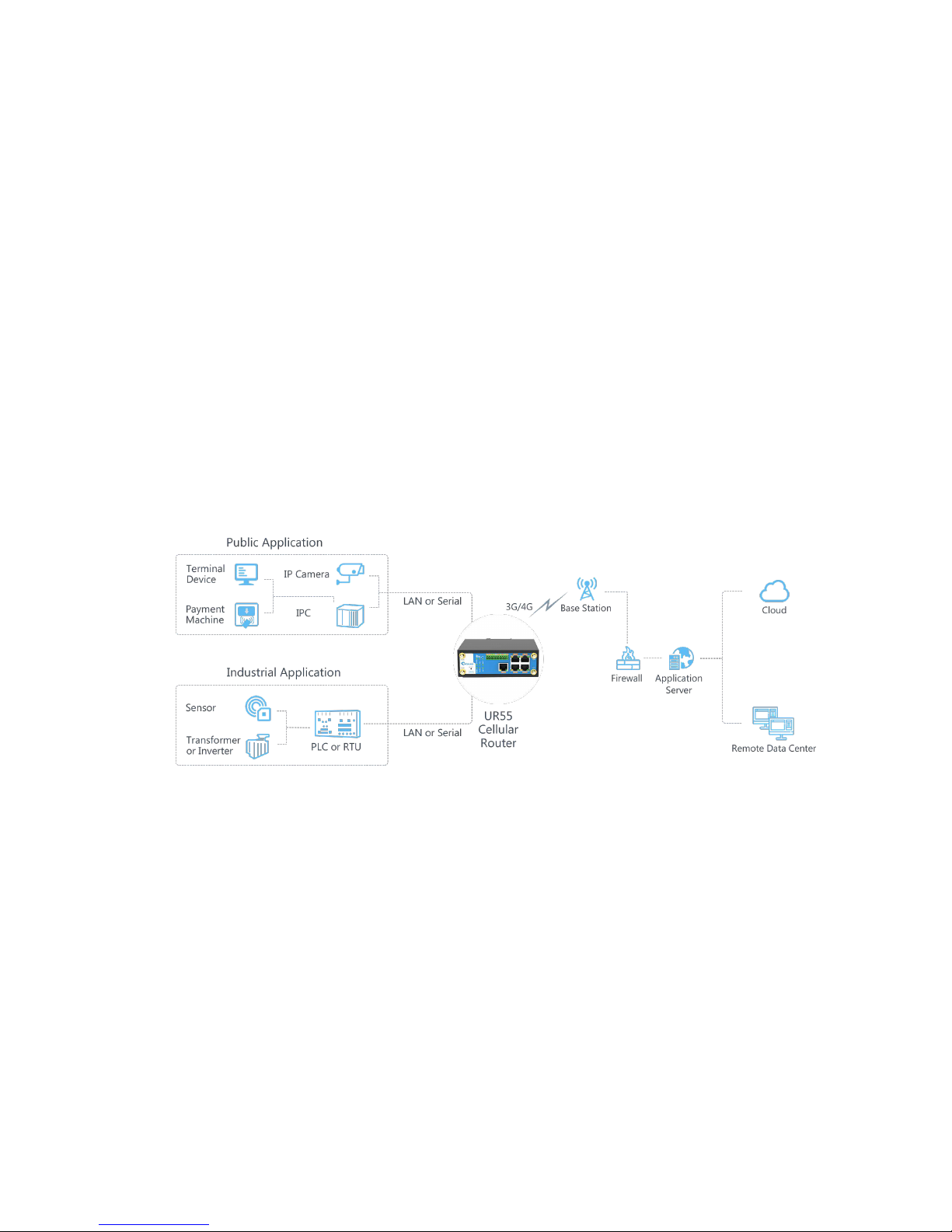
Ursalink UR52/UR55 is an industrial cellular router with embedded intelligent software features that are
designed for multifarious M2M/IoT applications. Supporting global WCDMA and 4G LTE, UR52/UR55
provides drop-in connectivity for operators and makes a giant leap in maximizing uptime.
Adopting high-performance and low-power consumption industrial grade CPU and wireless module, the
UR52/UR55 is capable of providing wire-speed network with low power consumption and ultra-small
package to ensure the extremely safe and reliable connection to the wireless network.
Meanwhile, the UR52/UR55 also supports Fast Ethernet ports, serial port (RS232/RS485) and I/O
(input/output), which enables you to scale up M2M application combining data and video in limited time
and budget.
The UR52/UR55 is particularly ideal for smart grid, digital media installations, industrial automation,
telemetry equipment, medical device, digital factory, finance, payment device, environment protection,
water conservancy and so on.
Figure 1-1
1.2 Advantages
Benefits
- Built-in industrial strong CPU, big memory
- Fast Ethernet is applied to all models of Ursalink routers for lightning transmission of data
- Dual SIM cards for backup between multiple carriers networking and global 2G/3G/LTE options make
it easy to get connected
- Flexible modular design provides users with different connection modules like Ethernet, I/O, serial
port, Wi-Fi, GPS for connecting diverse field assets
- Rugged enclosure, optimized for DIN rail or shelf mounting
- 3-year warranty included
Page 9

UR52 & UR55 User Guide
9
Security & Reliability
- Automated failover/failback between Ethernet and Cellular (dual SIM)
- Enable unit with security frameworks like IPsec/OpenVPN/GRE/L2TP/PPTP/ DMVPN
- Embed hardware watchdog, able to automatically recover from various failure, ensure highest level of
availability
- Establish a secured mechanism on centralized authentication and authorization of device access by
supporting AAA (TACACS+, Radius, LDAP, local authentication) and multiple levels of user authority
Easy Maintenance
- Ursalink DeviceHub provides easy setup, mass configuration, and centralized management of remote
devices
- The user-friendly web interface design and more than one option of upgrade help administrator to
manage the device as easy as pie
- WEB GUI and CLI enable the admin to achieve simple management and quick configuration among a
large quantity of devices
- Efficiently manage the remote routers on the existing platform through the industrial standard SNMP
Capabilities
- Link remote devices in an environment where communication technologies are constantly changing
- Industrial 32-bit ARM Cortex-A7 processor, high-performance operating up to 528MHz with low
power consumption below 1W, and 128 MB memory available to support more applications
- Support rich protocols like SNMP, MQTT, Modbus bridging, RIP, OSPF
- Support wide operating temperature ranging from -40°C to 70°C/-40°F to 158°F
Page 10

UR52 & UR55 User Guide
10
1.3 Specifications
Cellular Interfaces
Connectors
2 × 50 Ω SMA (Center pin: female)
SIM Slots
2
Wi-Fi Interface (Optional)
Connectors
1 × 50 Ω SMA (Center pin: female)
Standards
IEEE 802.11b/g/n/ac
Tx Power
802.11b: 16 dBm +/-1.5 dBm (11 Mbps)
802.11g: 15 dBm +/-1.5 dBm (54 Mbps)
[email protected] GHz: 14 dBm +/-1.5 dBm (HT20 MCS7)
802.11ac@5 GHz: 10 dBm +/-2 dBm (HT80 MCS9)
Rx Sensitivity
802.11b: <= -76 dBm (11 Mbps)
802.11g: <= -68 dBm (54 Mbps)
[email protected] GHz: <= -67 dBm (HT20 MCS7)
[email protected] GHz: <= -64 dBm (HT40 MCS7)
802.11n@5 GHz: <= -67 dBm (HT20 MCS7)
802.11n@5 GHz: <= -65 dBm (HT40 MCS7)
802.11ac@5 GHz: <= -54 dBm (HT80 MCS9)
Modes
Support AP and Client mode, multiple SSID
Security
WPA/WPA2 authentication, WEP/TKIP/AES encryption
GPS (Optional)
Connectors
1 × 50 Ω SMA (Center pin: female)
Sensitivity
-167dBm@Tracking, -149dBm@Acquisition, -161dBm@Re-Acquisition
Position Accuracy
<2.5m CEP
Protocols
NMEA 0183, PMTK
Hardware System
CPU
528MHz, 32-bit ARM Cortex-A7
Memory
128 MB Flash, 128 MB DDR3 RAM
Storage
1 × Micro SD
Ethernet
Ports
UR52: 2 × RJ-45
UR55: 5 × RJ-45
Physical Layer
10/100 Base-T (IEEE 802.3)
Data Rate
10/100 Mbps (auto-sensing)
Page 11

UR52 & UR55 User Guide
11
Physical Characteristics
Ingress Protection
IP30
Housing & Weight
UR52: Metal, 460 g (1.01 lb)
UR55: Metal, 481 g (1.06 lb)
Dimensions
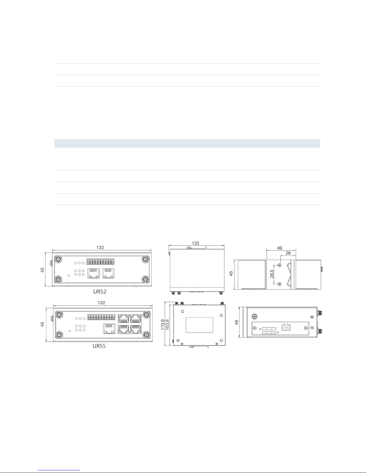
132 x 103.8 x 45 mm (5.20 x 4.09 x 1.77 in)
Mounting
Desktop, wall or DIN rail mounting
Others
Reset Button
1 × RESET
Interface
Auto MDI/MDIX
Mode
Full or half duplex (auto-sensing)
Serial Interface
Ports
1 × RS232 + 1 × RS485 or 2 × RS232 or 2 × RS485
Connector
Terminal block
Baud Rate
300bps to 230400bps
IO
Connector
(4) pin screw down terminal block
Digital
2 × DI + 2 × DO
Software
Network Protocols
PPP, PPPoE, SNMP v1/v2c/v3, TCP, UDP, DHCP, RIPv1/v2, OSPF, DDNS,
VRRP, HTTP, HTTPS, DNS, ARP, QoS, SNTP, Telnet, VLAN, SSH, etc.
VPN Tunnel
DMVPN/IPsec/OpenVPN/PPTP/L2TP/GRE
Access Authentication
CHAP/PAP/MS-CHAP/MS-CHAPV2
Firewall
ACL/DMZ/Port Mapping/MAC Binding
Management
Web, CLI, SMS, On-demand dial up
AAA
Radius, TACACS+, LDAP, Local Authentication
Multilevel Authority
Multiple levels of user authority
Reliability
VRRP, WAN Failover, Dual SIM Backup
Serial Port
Transparent (TCP Client/Server, UDP), Modbus Gateway (Modbus RTU to
Modbus TCP)
Power Supply and Consumption
Connector
2-pin with 5.08 mm terminal block
Input Voltage
9-48 VDC
Power Consumption
UR52: Typical 1.6 W (Max 3.0 W)
UR55: Typical 2.6 W (Max 4.3 W)
Page 12
UR52 & UR55 User Guide
12
LED Indicators
1 × POWER, 1 × WLAN, 1 × STATUS, 1 × VPN,
1 × SIM1, 1 × SIM2, 3 × Signal strength
Built-in
Watchdog, RTC, Timer
Certifications
RoHS, CE, FCC
EMC
IEC 61000-4-2 Level 3
IEC 61000-4-3 Level 3
IEC 61000-4-4 Level 4
IEC 61000-4-5 Level 4
IEC 61000-4-6 Level 3
IEC 61000-4-8 Level 4
Environmental
Operating Temperature
-40°C to +70°C (-40°F to +158°F) Reduced cellular performance above
60°C
Storage Temperature
-40°C to +85°C (-40°F to +185°F)
Ethernet Isolation
1.5 kV RMS
Relative Humidity
0% to 95% (non-condensing) at 25°C/77°F
1.4 Dimensions (mm)
Figure 1-2
Page 13
UR52 & UR55 User Guide
13
Chapter 2 Installation
2.1 General Packing List
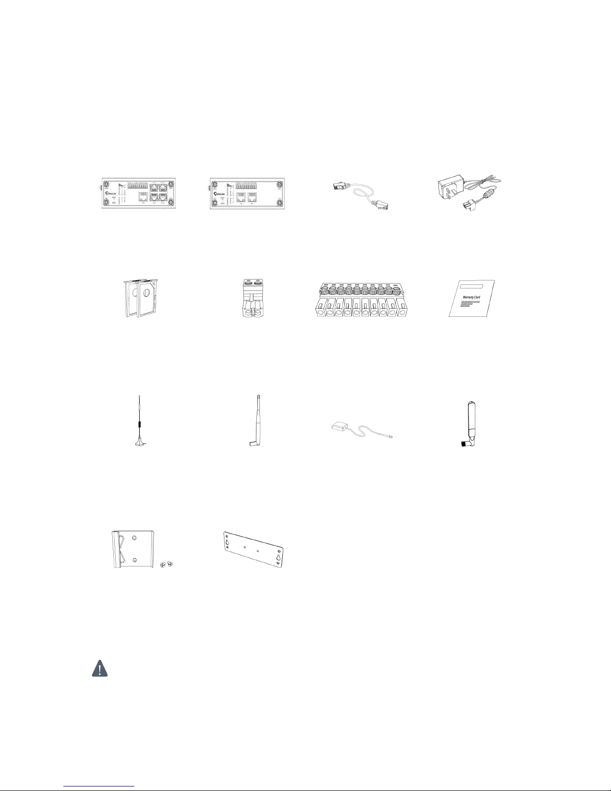
Before you begin to install the UR52/UR55 router, please check the package contents to verify that you
have received the items below.
1 × UR55 Router or
1 × UR52 Router
1 × Ethernet Cable
1 × Power Adapter
2 × SIM Card Slots
1 × 2-PIN Pluggable
Terminal
1 × 10-PIN
Pluggable Terminal
1 × Warranty Card
2 × Magnetic Mount
Cellular Antennas
(Default)
2 × Stubby Cellular
Antennas (Optional)
1 × GPS Antenna
(Optional)
1× Stubby Wi-Fi
Antennas (Optional)
1 × DIN Rail Kit
(Default)
1×Wall Mounting
Bracket (Optional)
If any of the above items is missing or damaged, please contact your Ursalink sales
representative.
Page 14
UR52 & UR55 User Guide
14
2.2 Product Overview
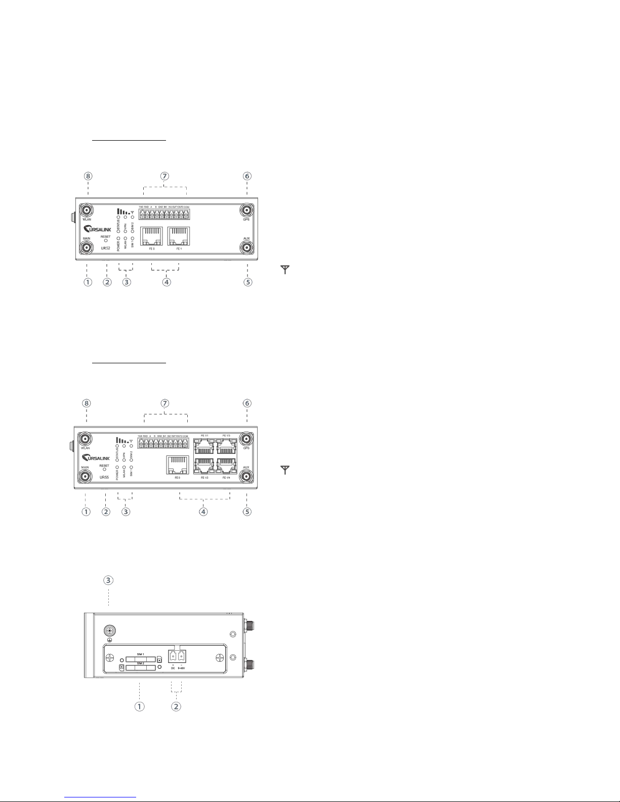
A. Front Panel
UR52 Front Panel
① Main Cellular Antenna Connector ② Reset Button
③ LED Indicator Area
POWER: Power Indicator STATUS: Status Indicator
WLAN: Wi-Fi Indicator VPN: VPN Indicator
SIM1: SIM1 Status Indicator SIM2: SIM2 Status Indicator
: Signal Strength Indicator
④ Ethernet Port Indicator
⑤ AUX Cellular Antenna Connector
⑥ GPS Antenna Connector ⑦ Serial Port & I/O
⑧ Wi-Fi Antenna Connector
UR55 Front Panel
① Main Cellular Antenna Connector ② Reset Button
③ LED Indicator Area
POWER: Power Indicator STATUS: Status Indicator
WLAN: Wi-Fi Indicator VPN: VPN Indicator
SIM1: SIM1 Status Indicator SIM2: SIM2 Status Indicator
: Signal Strength Indicator
④ Ethernet Port Indicator
⑤ AUX Cellular Antenna Connector
⑥ GPS Antenna Connector ⑦ Serial Port & I/O
⑧ Wi-Fi Antenna Connector
B. Left Side Panel
① SIM Card Slot
② Power Connector
③ Grounding Stud
Page 15
UR52 & UR55 User Guide
15
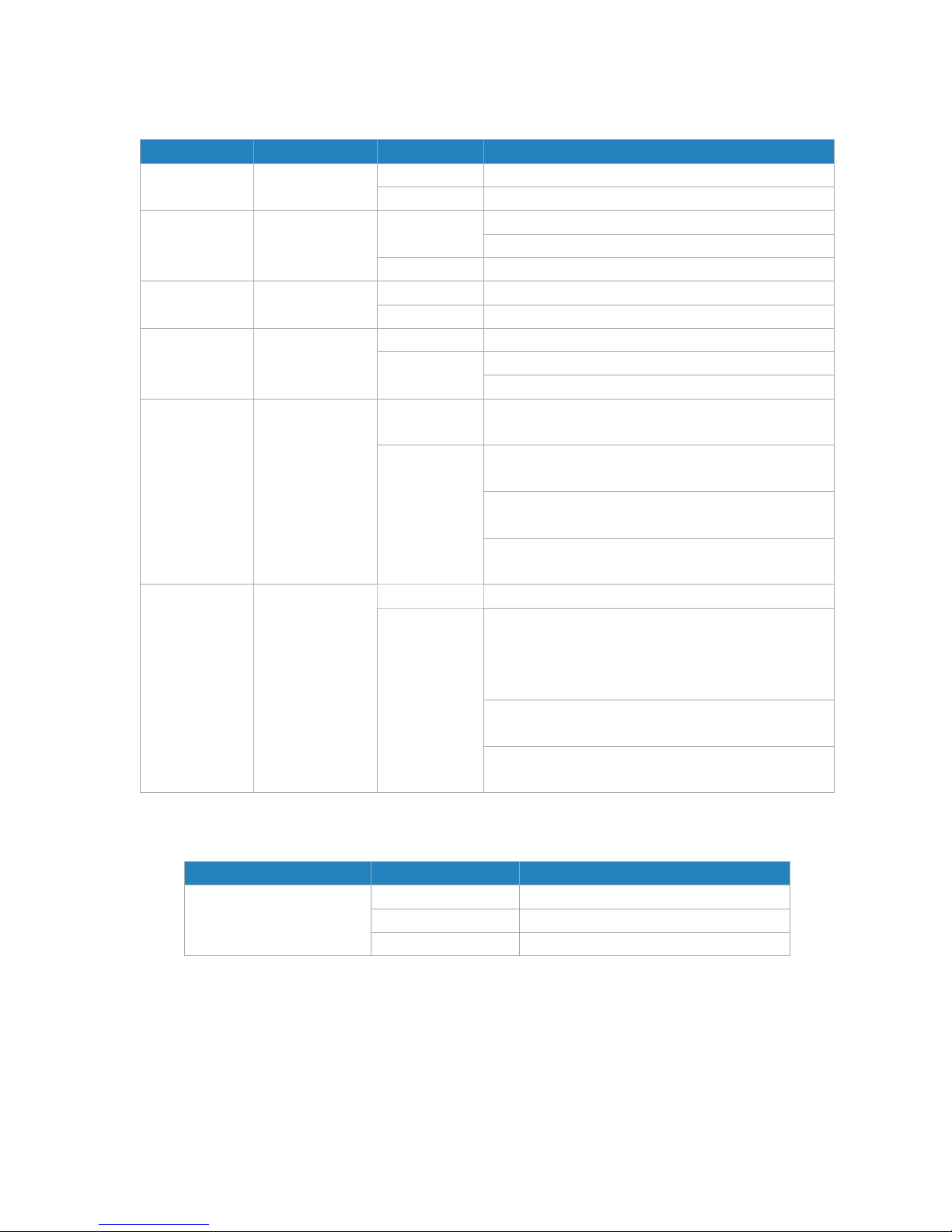
2.3 LED Indicators
LED
Indication
Status
Description
POWER
Power Status
Off
The power is switched off
On
The power is switched on
STATUS
System Status
Green Light
Static: Start-up
Blinking slowly: the system is running properly
Red Light
The system goes wrong
VPN
VPN Status
Off
VPN is disconnected
Green Light
VPN is connected
WLAN (Wi-Fi)
WLAN Status
Off
Wi-Fi is disabled
Green Light
Static: Wi-Fi is enabled
Blinking slowly: sending or receiving data via Wi-Fi
SIM1/SIM2
SIM Card Status
Off
SIM1 or SIM2 is registering or fails to register (or
there are no SIM cards inserted)
Green Light
Blinking slowly: SIM1 or SIM2 has been registered
and is ready for dial-up
Blinking rapidly: SIM1 or SIM2 has been registered
and is dialing up now
Static: SIM1 or SIM2 has been registered and
dialed up successfully
Signal Strength
Signal 1/2/3
Off
No signal
Green Light
Static/Off/Off: weak signal with 1-10 ASU (please
check if the antenna is installed correctly or move
the antenna to a suitable location to get better
signal)
Static/Static/Off: normal signal with 11-20 ASU.
(average signal strength)
Static/Static/Static: strong signal with 21-31 ASU
(signal is good)
2.4 Ethernet Port Indicators
Indicator
Status
Description
Link Indicator (Orange)
Off
Disconnected
Blinking
Transmitting data
On
Connected
Page 16
UR52 & UR55 User Guide
16
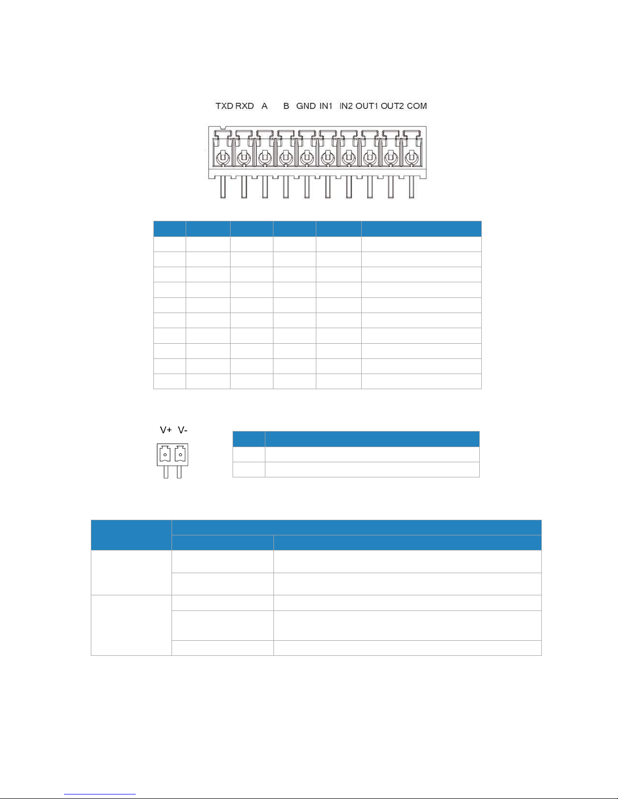
2.5 PIN Definition
2.6 Reset Button
Function
Description
STATUS LED
Action
Reboot
Blinking
Press and hold the reset button for about 5-15 seconds.
Static Green
Release the button and wait for system to reboot.
Reset
Blinking
Press and hold the reset button for more than 15 seconds.
Static Green →
Rapidly Blinking
Release the button and wait.
Off → Blinking
The router is now reset to factory defaults.
PIN
RS232
RS485DIDO
Description
1
TXD
---
---
---
Transmit Data
2
RXD
---
---
---
Receive Data
3
---A---
---
Data +
4
---B---
---
Data -
5
GND
---
GND
---
Ground
6
---
---
IN1
---
Digital Input1
7
---
---
IN2
---
Digital Input2
8
---
---
---
OUT1
Digital Output1
9
---
---
---
OUT2
Digital Output2
10
---
---
---
COM
Common Ground
PIN
Description
11
Positive
12
Negative
Page 17
UR52 & UR55 User Guide
17
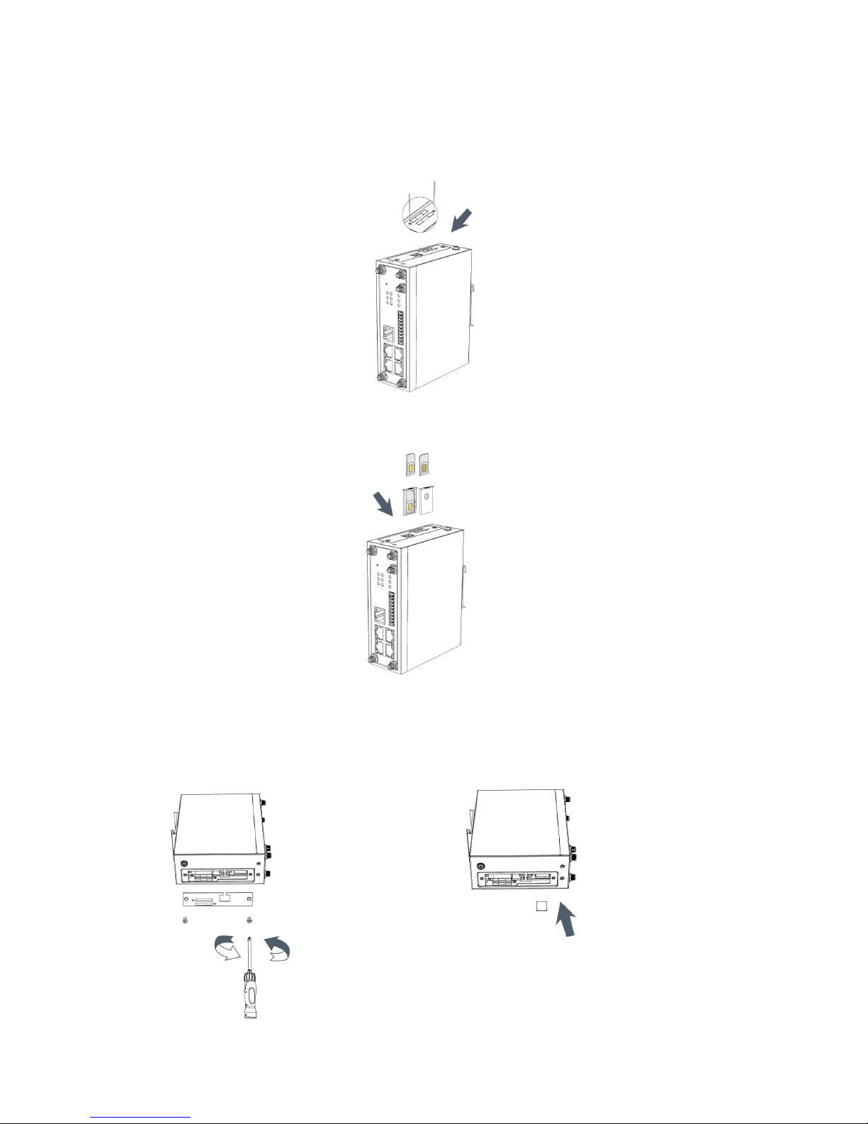
2.7 SIM Card Installation
A. Push the yellow button on left panel of the router, and then you will see the SIM card slot popping out
directly.
B. Put SIM card onto the slot, and then insert the slot back into the hole.
2.8 Micro SD card Installation
A. Unscrew the cover on left panel B. Insert Micro SD card.
of the router and then take it off.
Page 18
UR52 & UR55 User Guide
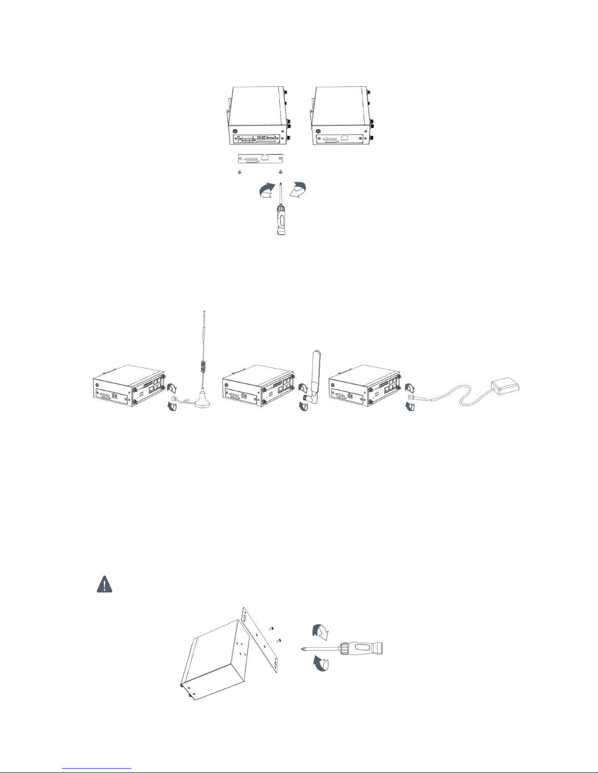
18
C. Close the cover and screw it back to the router.
2.9 Antenna Installation
Rotate the antenna into the antenna connector accordingly.
The external cellular antenna should be installed vertically always on a site with a good cellular signal.
Note: UR52/UR55 router supports dual antennas with “Main” and “AUX” connectors. “Main” interface
is for data receiving and transmission. “AUX” interface is for enhancing signal strength, which cannot be
used separately.
2.10 Mounting the Router
The router can be placed on a desktop or mounted to a wall or a DIN rail.
2.10.1 Wall Mounting (Measured in mm)
Use 2 pcs of M3×6 flat head Phillips screws to fix the wall mounting kit to the router, and then use 2 pcs of
M3 drywall screws to mount the router associated with the wall mounting kit on the wall.
Recommended torque for mounting is 1.0 N. m, and the maximum allowed is 1.2 N.m.
Page 19
UR52 & UR55 User Guide
19
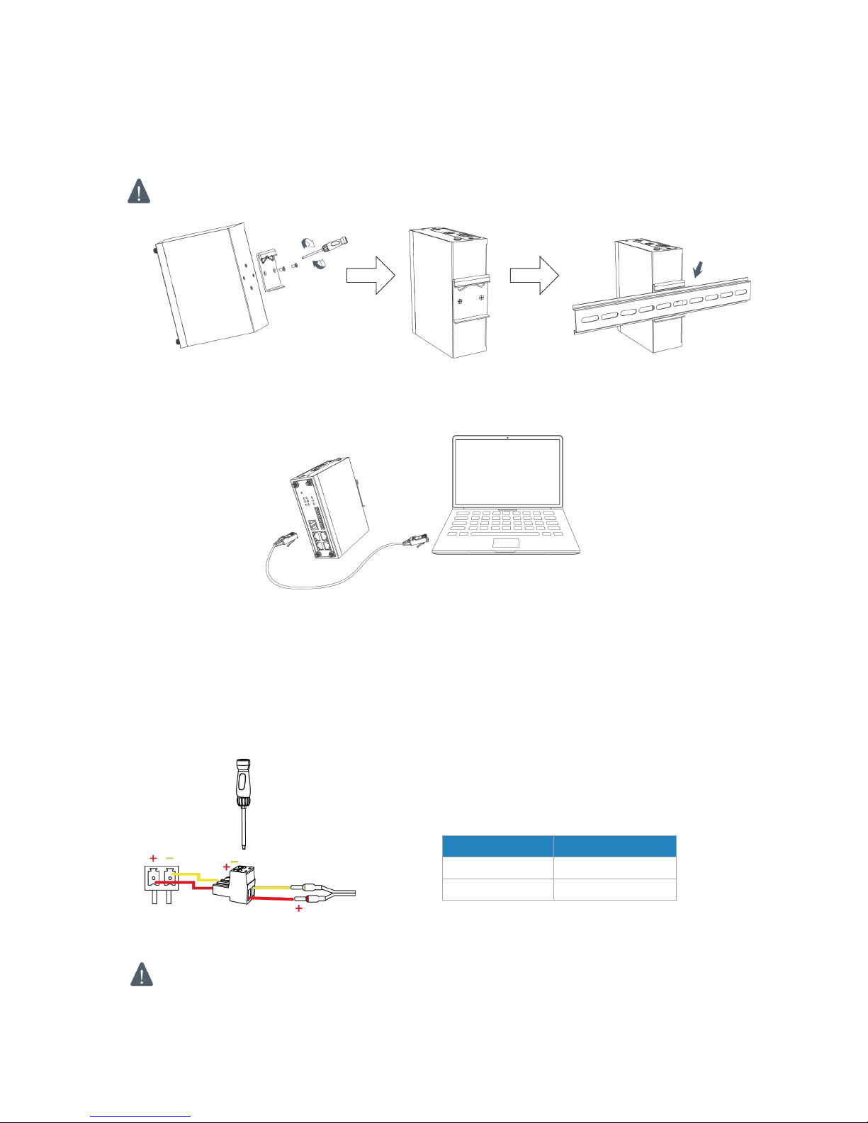
2.10.2 DIN Rail Mounting (Measured in mm)
Use 2 pcs of M3×6 flat head Phillips screws to fix the DIN rail to the router, and then hang the DIN rail on
the mounting bracket. It is necessary to choose a standard bracket.
Recommended torque for mounting is 1.0 N. m, and the maximum allowed is 1.2 N.m.
2.11 Connect the Router to a Computer
Please connect PC to any port among FE 1/1-FE1/4 of UR55 router, or to FE1 of UR52 router with Ethernet
cable directly.
2.12 Installation of Power Supply and Protective Grounding
2.12.1 Power Supply Installation
A. Take out the terminal from the router and unscrew the bolt on terminal.
B. Screw down the bolt after inserting power cable into the terminal.
Connecting the Power Cable
If you insert wires into the reverse holes, the router will not start and you must switch the wires
into the correct holes.
Color
Polarity
Red
+
Yellow
-
Page 20
UR52 & UR55 User Guide
20
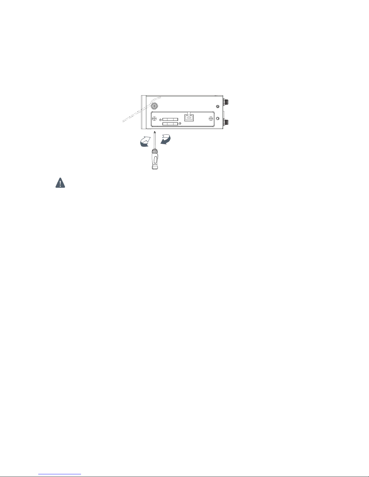
2.12.2 Protective Grounding Installation
1. Remove the grounding nut.
2. Connect the grounding ring of the cabinet’s grounding wire onto the grounding stud and screw up
the grounding nut.
The router must be grounded when deployed. According to operating environment, the ground
wire should be connected with grounding stud of router.
2.13 Examine
1. Double check antenna connection.
2. Double check if SIM card is inserted and become available.
3. Power on the UR52/UR55 wireless cellular router and check indicators status.
(1) If Status LED blinks slowly, the system is running properly.
(2) If SIM1 or SIM2 indicator is static green, the router is connected to network already.
Page 21
UR52 & UR55 User Guide
21
Chapter 3 Access to Web GUI
This chapter explains how to access to Web GUI of the UR52/UR55 router.
3.1 PC Configuration for Web GUI Access to Router
Please connect PC to any port among FE 1/1-FE 1/4 of UR55 router, or to FE 1 of UR52 router directly. PC
can obtain an IP address, or you can configure a static IP address manually.
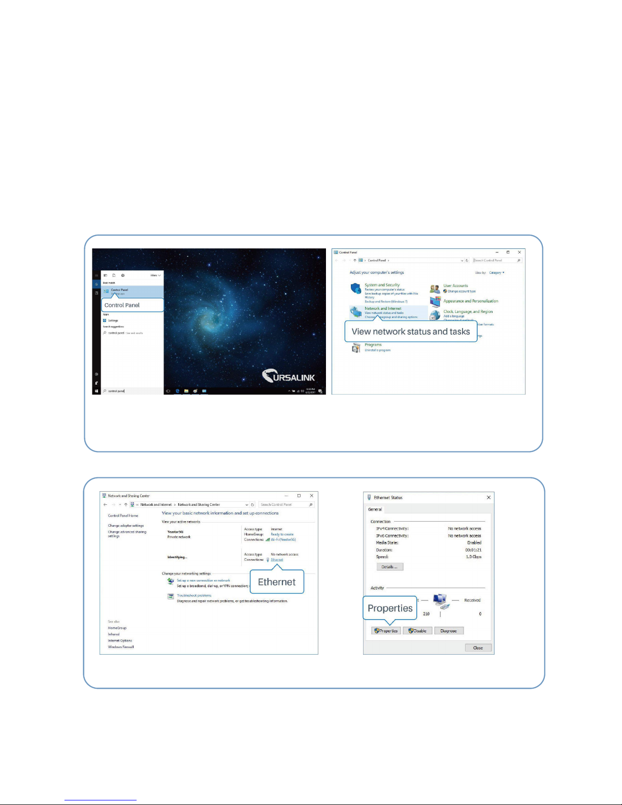
The following steps are based on Windows 10 operating system for your reference.
(Note: as remote access is disabled by default, you can't access to the router's Web GUI when you
connect PC to FE 0 of the router. But it will function properly if you enable it on the Web GUI.)
①Click "Search Box" to search "Control Panel" on
the Windows 10 taskbar.
② Click “Control Panel” to open it, and then
click “View network status and tasks”.
④ Click "Properties".
③ Click "Ethernet" (May have different name).
Page 22
UR52 & UR55 User Guide
22
3.2 Access to Web GUI of Router
Ursalink router provides Web-based configuration interface for management. If this is the first time you
configure the router, please use the default settings below.
Username: admin
Password: password
IP Address: 192.168.1.1
DHCP Server: Enabled
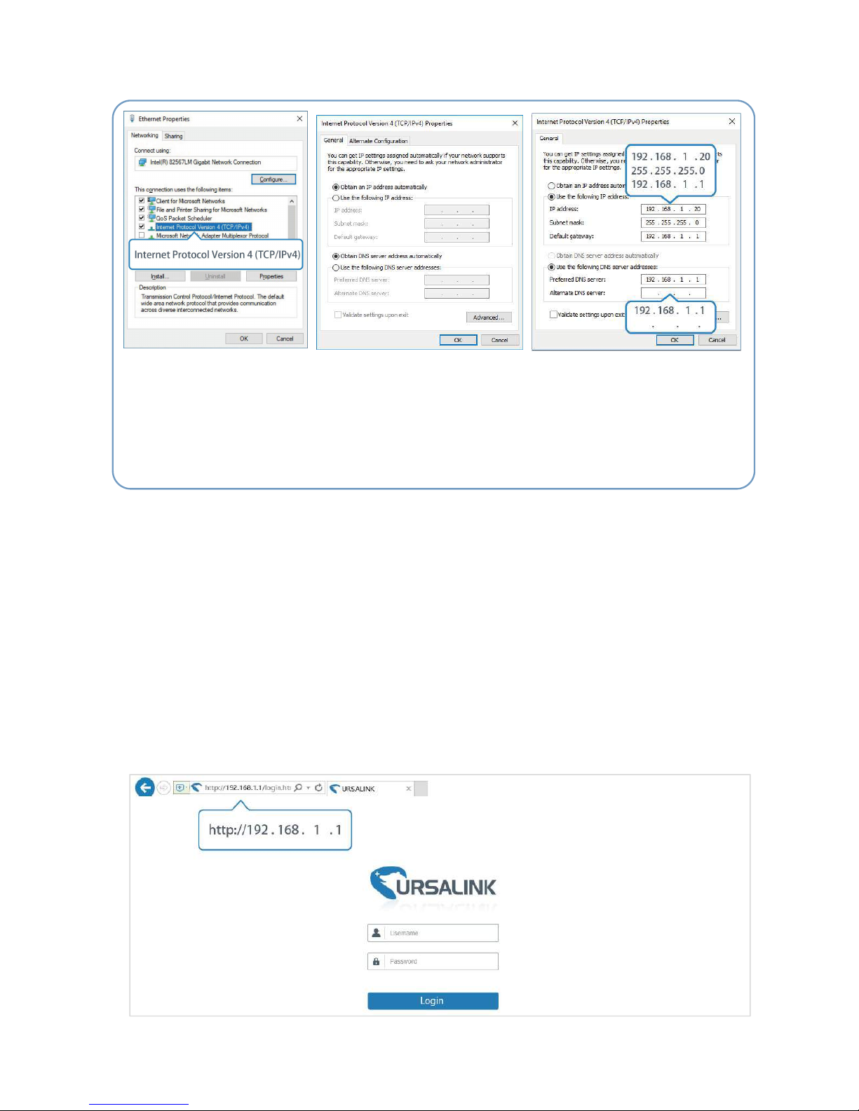
1. Start a Web browser on your PC (Chrome and IE are recommended), type in the IP address, and press
Enter on your keyboard.
2. Enter the username, password, and click "Login".
⑤ Double Click "Internet
Protocol Version 4 (TCP/IPv4)"
to configure IP address and
DNS server.
⑥ Method 1: click "Obtain an IP
address automatically";
Method 2: click "Use the following
IP address" to assign a static IP
manually within the same subnet of
the router.
(Note: remember to click “OK” to finish configuration.)
Page 23
UR52 & UR55 User Guide
23
If the SIM card is connected to cellular network with public IP address, you can access WEB GUI remotely
via the public IP address when remote access is enabled.
If you enter the username or password incorrectly more than 5 times, the login page will be
locked for 10 minutes.
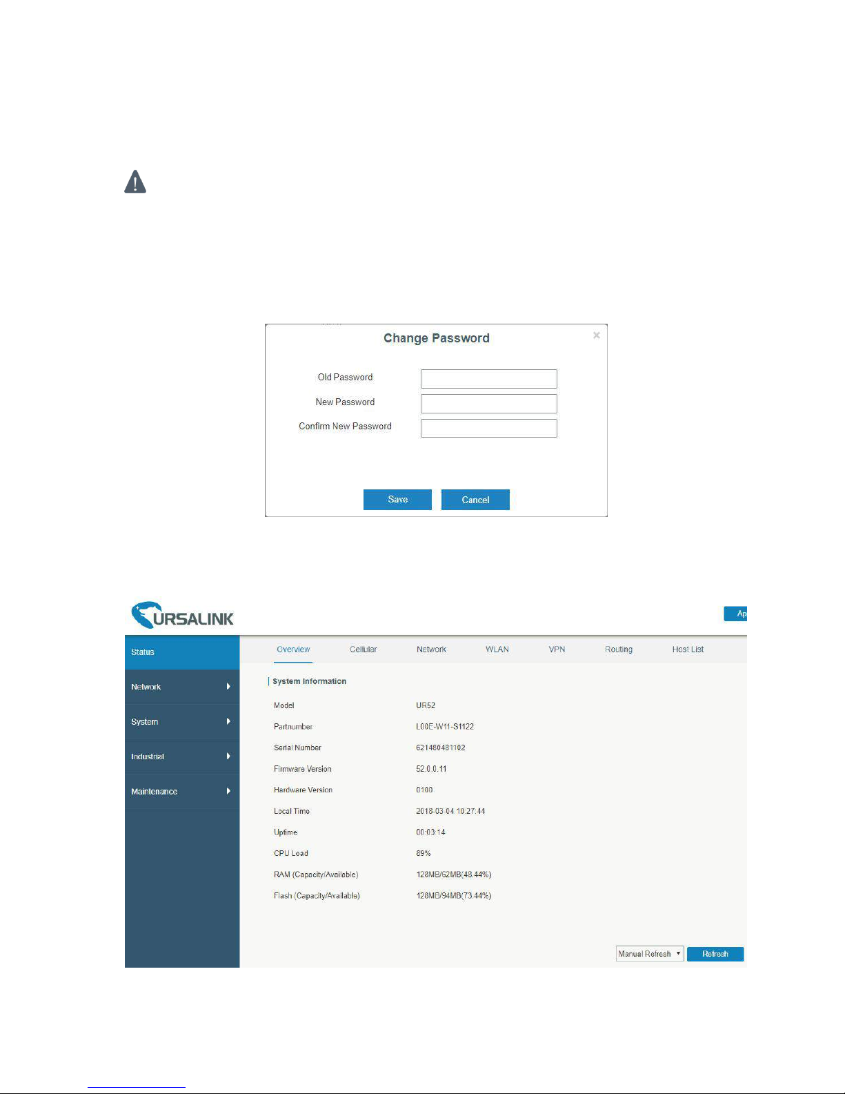
3. When you login with the default username and password, you will be asked to modify the password.
It’s suggested that you change the password for the sake of security. Click "Cancel" button if you
want to modify it later.
4. After you login the Web GUI, you can view system information and perform configuration on the
router.
Page 24
UR52 & UR55 User Guide
24
Chapter 4 Web Configuration
4.1 Status
4.1.1 Overview
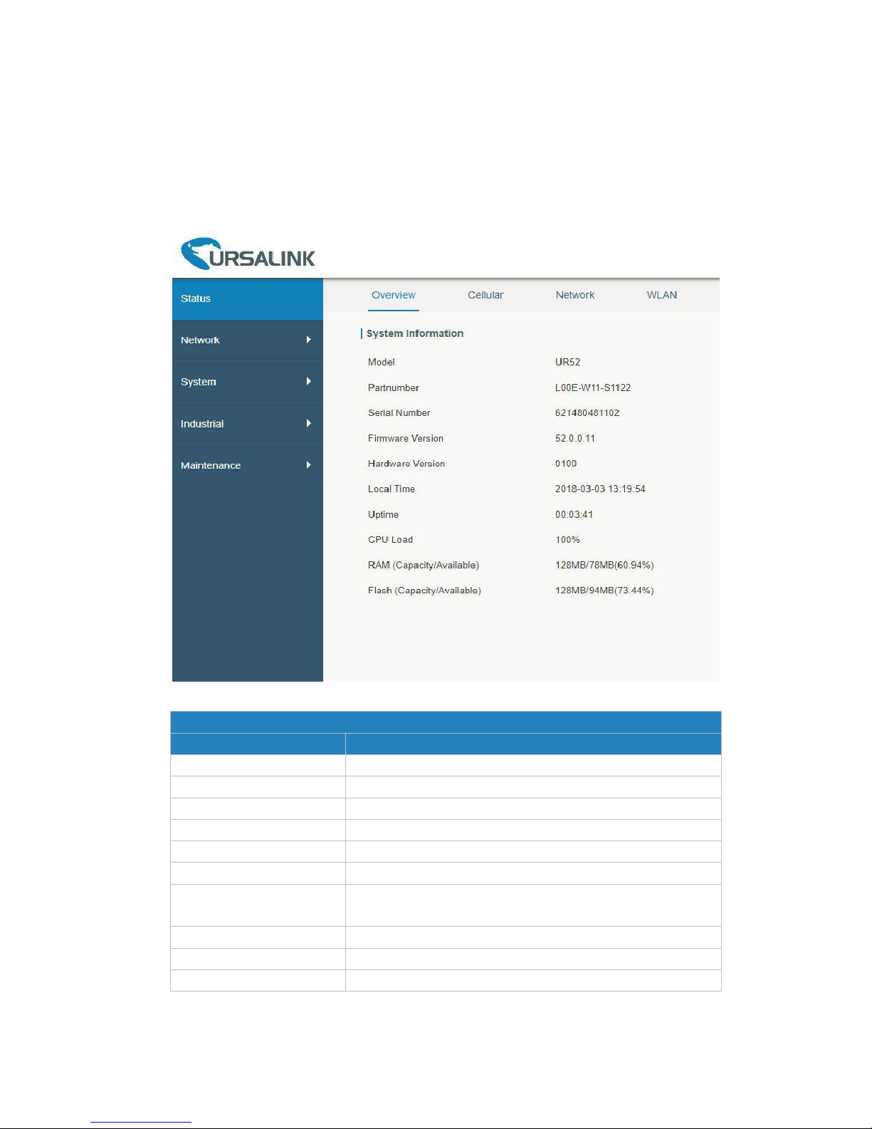
You can view the system information of the router on this page.
Figure 4-1-1-1
System Information
Item
Description
Model
Show the model name of router.
Part Number
Show the part number of router.
Serial Number
Show the serial number of router.
Firmware Version
Show the currently firmware version of router.
Hardware Version
Show the currently hardware version of router.
Local Time
Show the currently local time of system.
Uptime
Show the information on how long the router has been
running.
CPU Load
Show the current CPU utilization of the router.
RAM (Capacity/Available)
Show the RAM capacity and the available RAM memory.
Flash (Capacity/Available)
Show the Flash capacity and the available Flash memory.
Table 4-1-1-1 System Information
Page 25
UR52 & UR55 User Guide
25
4.1.2 Cellular
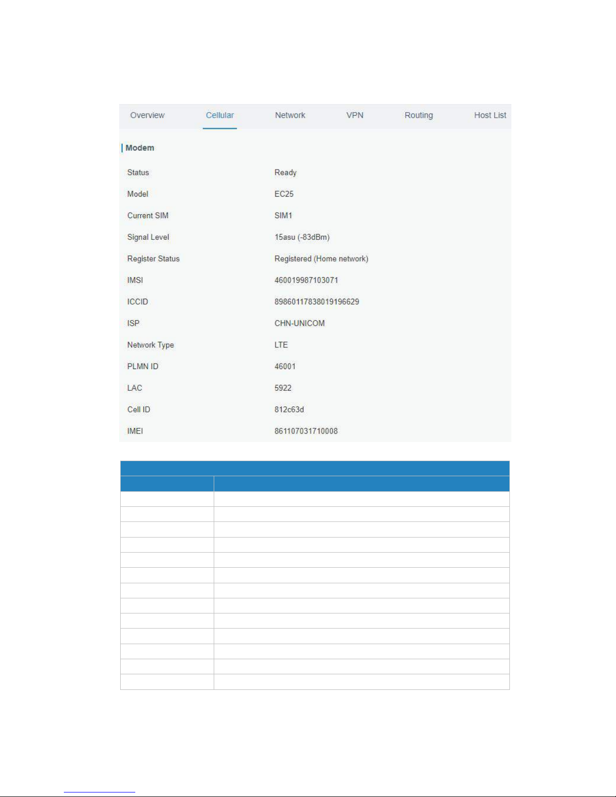
You can view the cellular network status of router on this page.
Figure 4-1-2-1
Modem Information
Item
Description
Status
Show corresponding detection status of module and SIM card.
Model
Show the model name of cellular module.
Current SIM
Show the current SIM card used.
Signal Level
Show the cellular signal level.
Register Status
Show the registration status of SIM card.
IMSI
Show IMSI of the SIM card.
ICCID
Show ICCID of the SIM card.
ISP
Show the network provider which the SIM card registers on.
Network Type
Show the connected network type, such as LTE, 3G, etc.
PLMN ID
Show the current PLMN ID, including MCC, MNC, LAC and Cell ID.
LAC
Show the location area code of the SIM card.
Cell ID
Show the Cell ID of the SIM card location.
IMEI
Show the IMEI of the module.
Table 4-1-2-1 Modem Information
Page 26
UR52 & UR55 User Guide
26
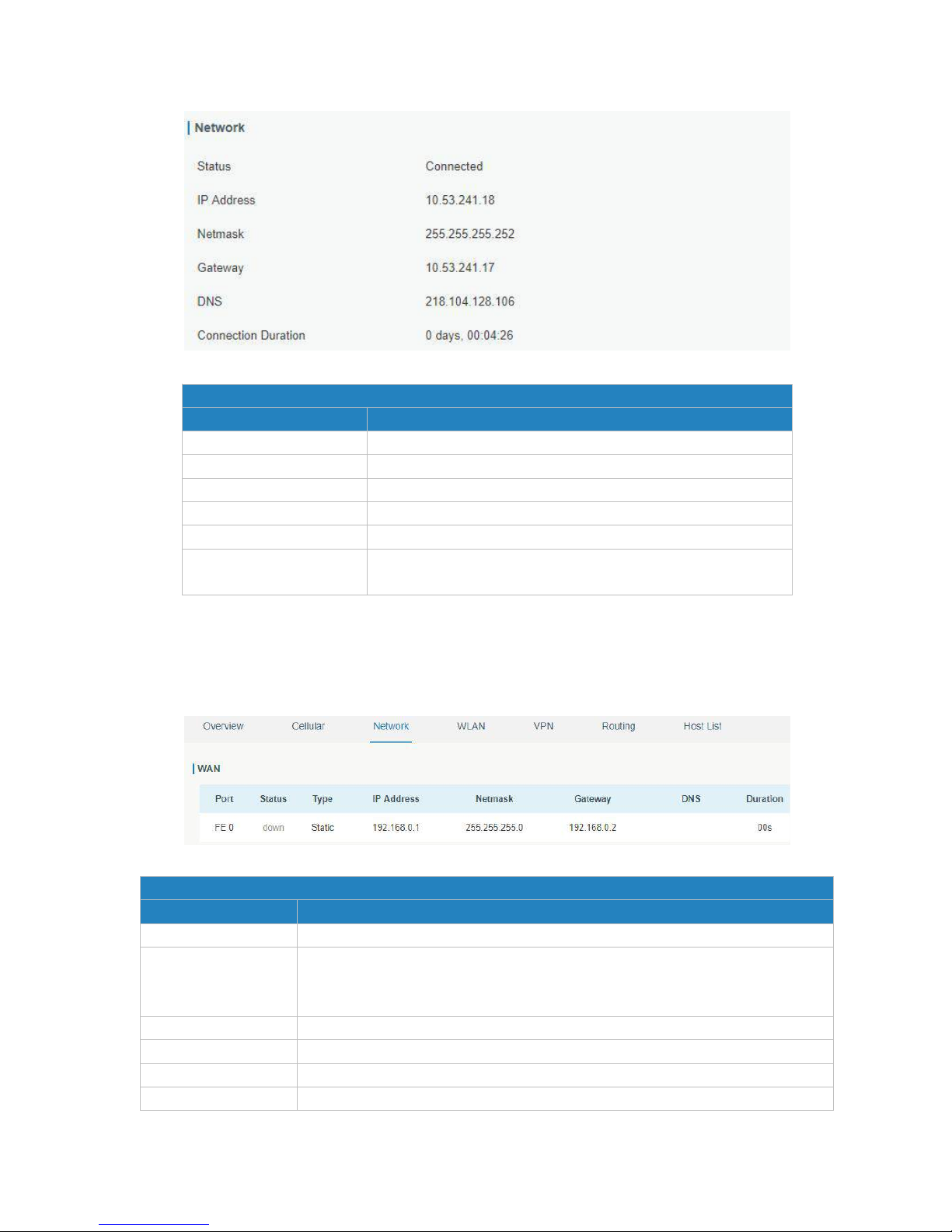
Figure 4-1-2-2
Network Status
Item
Description
Status
Show the connection status of cellular network.
IP Address
Show the IP address of cellular network.
Netmask
Show the netmask of cellular network.
Gateway
Show the gateway of cellular network.
DNS
Show the DNS of cellular network.
Connection Duration
Show information on how long the cellular network has been
connected.
Table 4-1-2-2 Network Status
4.1.3 Network
On this page you can check the WAN and LAN status of the router.
Figure 4-1-3-1
WAN Status
Item
Description
Port
Show the name of WAN port.
Status
Show the status of WAN port. "up" refers to a status that WAN is enabled and
Ethernet cable is connected. "down" means Ethernet cable is disconnected or
WAN function is disabled.
Type
Show the dial-up connection type of WAN port.
IP Address
Show the IP address of WAN port.
Netmask
Show the netmask of WAN port.
Gateway
Show the gateway of WAN port.
Page 27
UR52 & UR55 User Guide
27
DNS
Show the DNS of WAN port.
Connection Duration
Show the information on how long the Ethernet cable has been connected on
WAN port when WAN function is enabled. Once WAN function is disabled or
Ethernet connection is disconnected, the duration will stop.
Table 4-1-3-1 WAN Status
Figure 4-1-3-2
LAN Status
Item
Description
Port
Show the name of LAN port.
VLAN ID
Show the label ID of the VLAN.
IP Address
Show the LAN port's IP address.
Netmask
Show the LAN port's netmask.
MTU
Show the maximum transmission unit of LAN port.
Table 4-1-3-2 LAN Status
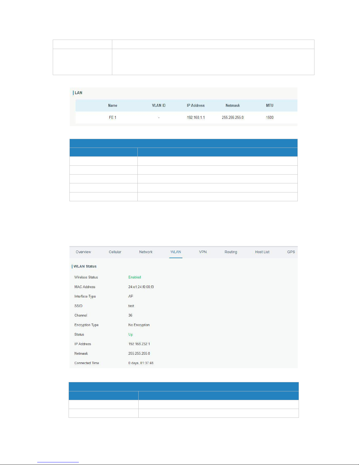
4.1.4 WLAN (Only Applicable to Wi-Fi Version)
You can check Wi-Fi status on this page, including the information of access point and client.
Figure 4-1-4-1
WLAN Status
Item
Description
Wireless Status
Show the wireless status.
MAC Address
Show the MAC address.
Page 28
UR52 & UR55 User Guide
28
Interface Type
Show the interface type, such as "AP" or “Client".
SSID
Show the SSID.
Channel
Show the wireless channel.
Authentication Type
Show the authentication type.
Encryption Type
Show the encryption type.
Status
Show the connection status.
IP Address
Show the IP address of the router.
Netmask
Show the wireless MAC address of the router.
Gateway
Show the gateway address in wireless network.
Connection Duration
Show information on how long the Wi-Fi network has been
connected.
Table 4-1-4-1 WLAN Status
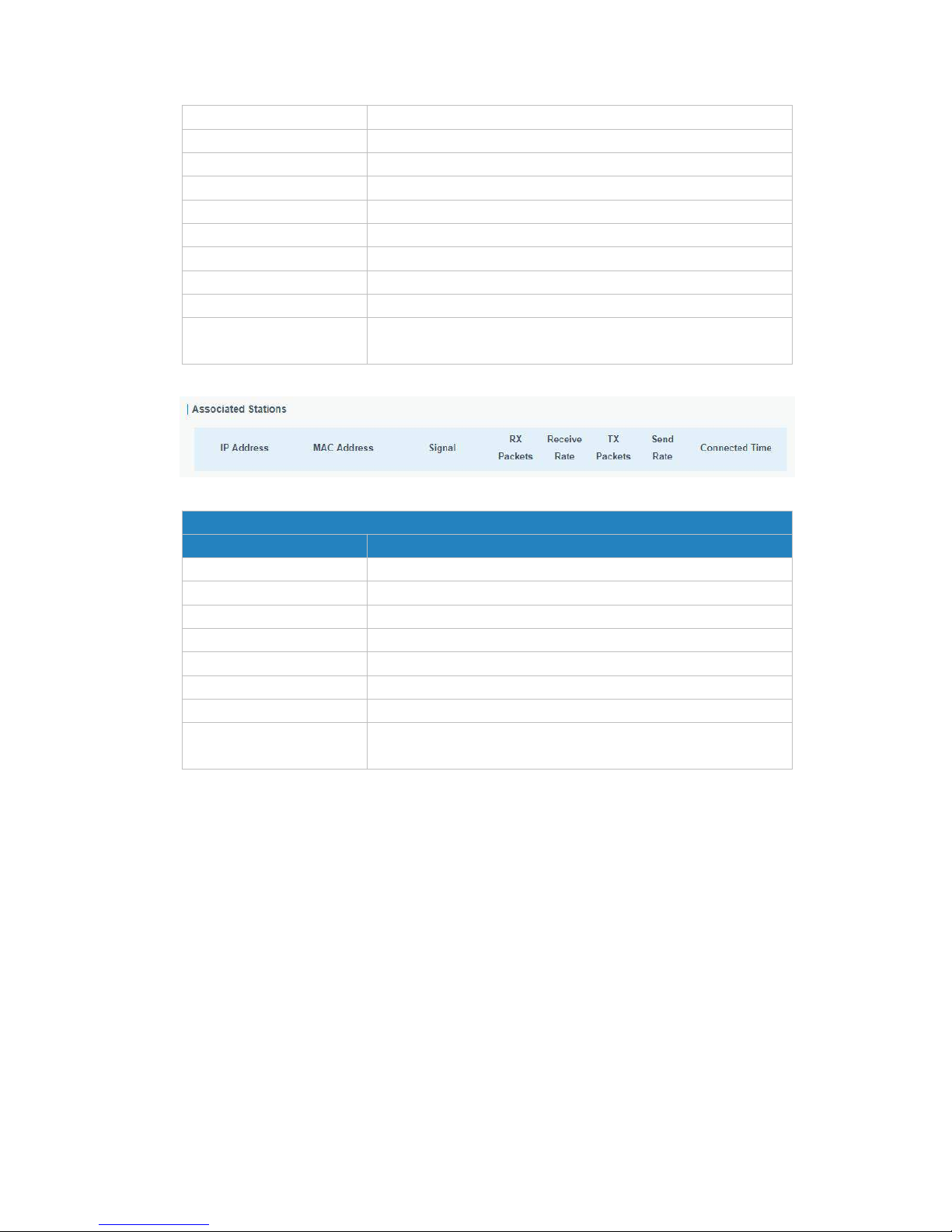
Figure 4-1-4-2
Associated Stations
Item
Description
IP Address
Show the IP address of access point or client.
MAC Address
Show the MAC address of the access point or client.
Signal
Show the wireless signal.
RX Packets
Show the packets size of received data.
Receive Rate
Show the receive rate of data.
TX Packets
Show the packets size of transmitted data.
Send Rate
Show the send rate of data.
Connection Duration
Show information on how long the Wi-Fi network has been
connected.
Table 4-1-4-2 WLAN Status
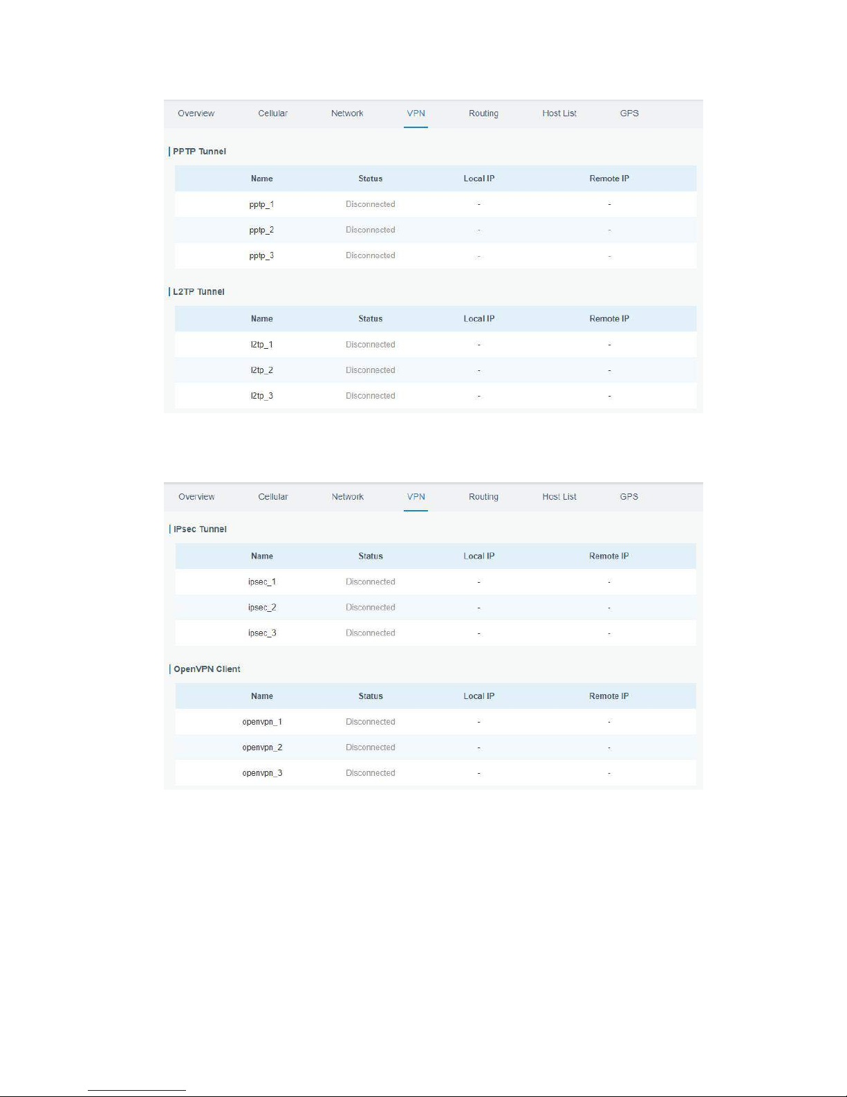
4.1.5 VPN
You can check VPN status on this page, including PPTP, L2TP, IPsec, OpenVPN and DMVPN.
Page 29
UR52 & UR55 User Guide
29
Figure 4-1-5-1
Figure 4-1-5-2
Page 30
UR52 & UR55 User Guide
30
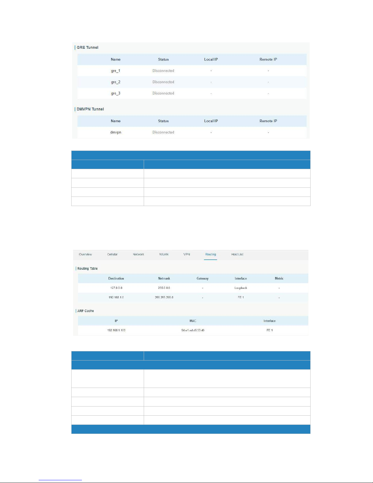
Figure 4-1-5-3
VPN Status
Item
Description
Name
Show the name of the VPN tunnel.
Status
Show the status of the VPN tunnel.
Local IP
Show the local tunnel IP of VPN tunnel.
Remote IP
Show the remote tunnel IP of VPN tunnel.
Table 4-1-5-1 VPN Status
4.1.6 Routing Information
You can check routing status on this page, including the routing table and ARP cache.
Figure 4-1-6-1
Item
Description
Routing Table
Destination
Show the IP address of destination host or destination
network.
Netmask
Show the netmask of destination host or destination network.
Gateway
Show the IP address of the gateway.
Interface
Show the outbound interface of the route.
Metric
Show the metric of the route.
ARP Cache
Page 31
UR52 & UR55 User Guide
31
IP
Show the IP address of ARP pool.
MAC
Show the IP address's corresponding MAC address.
Interface
Show the binding interface of ARP.
Table 4-1-6-1 Routing Information
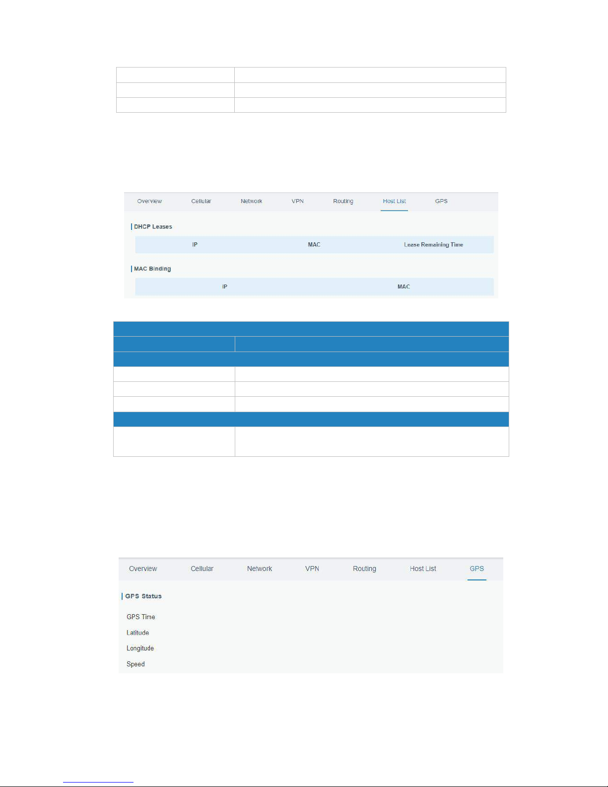
4.1.7 Host List
You can view the host information on this page.
Figure 4-1-7-1
Host List
Item
Description
DHCP Leases
IP Address
Show IP address of DHCP client
MAC Address
Show MAC address of DHCP client
Lease Time Remaining
Show the remaining lease time of DHCP client.
MAC Binding
IP & MAC
Show the IP address and MAC address set in the Static IP list of
DHCP service.
Table 4-1-7-1 Host List Description
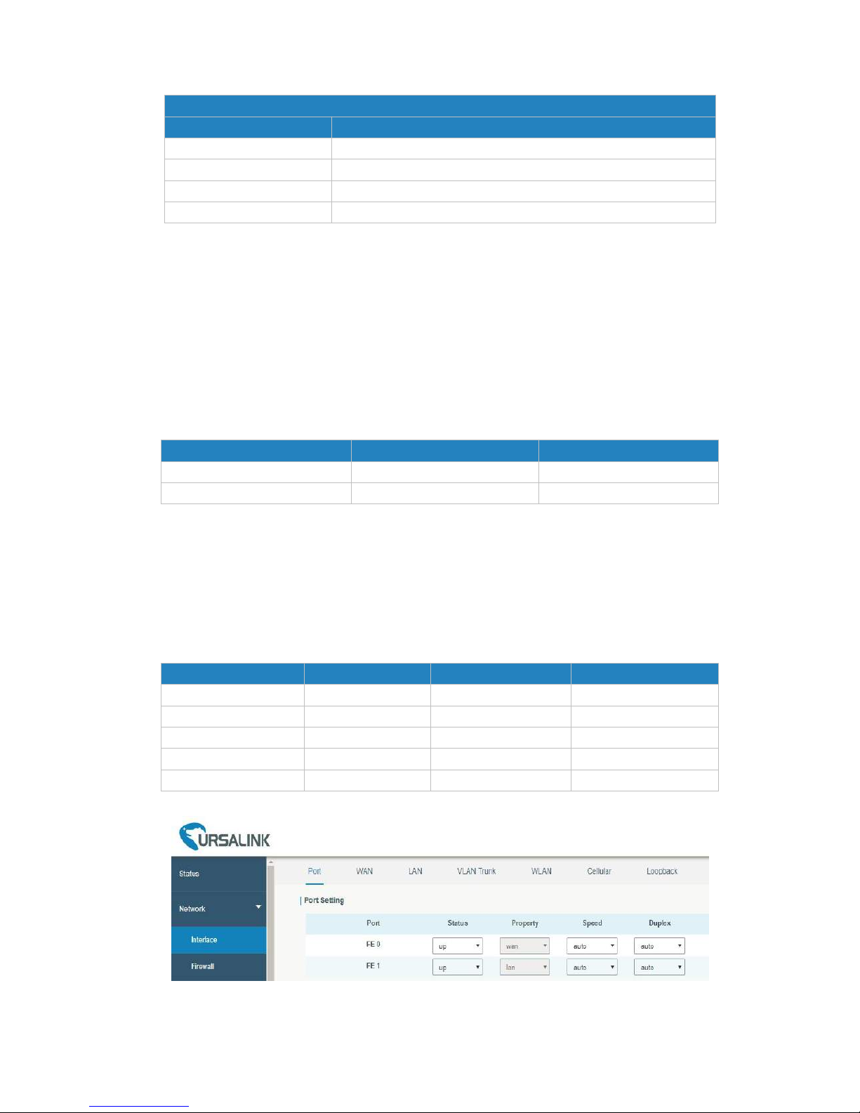
4.1.8 GPS
When GPS function is enabled and the GPS information is obtained successfully, you can view the latest
GPS information including GPS Time, Latitude, Longitude and Speed on this page.
Figure 4-1-8-1
Page 32
UR52 & UR55 User Guide
32
GPS Status
Item
Description
Time for Locating
Show the time for locating.
Latitude
Show the Latitude of the location.
Longitude
Show the Longitude of the location.
Speed
Show the speed of movement.
4.2 Network
4.2.1 Interface
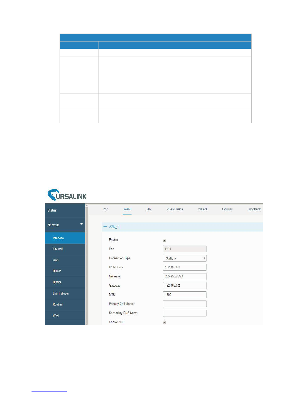
4.2.1.1 Port
This section describes how to configure the Ethernet port parameters.
(1) Ethernet Ports of UR52
The UR52 cellular router supports 2 Fast Ethernet ports, named FE 0 and FE 1.
Definition of the 2 Ethernet ports is listed below.
Port
Definition
Default IP Address
FE 0
WAN
192.168.0.1
FE 1
LAN
192.168.1.1
Table 4-2-1-1 Definition of 2 Ethernet Ports
(2) Ethernet Ports of UR55
The UR55 industrial cellular router features 5 Fast Ethernet ports, named FE 0, FE 1/1, FE 1/2, FE 1/3 and
FE 1/4. Among which, FE 0 is set as WAN port by default for accessing to public network and its property
cannot be changed. While the rest from FE 1/1 to FE 1/4 are considered as LAN ports by default for
connections with local private network. They can be defined as an additional WAN port, however, only
one of them could be activated at one time.
Port
Definition
Default Definition
Default IP Address
FE 0
WAN
WAN
192.168.0.1
FE 1/1
LAN or WAN
LAN
192.168.1.1
FE 1/2
LAN or WAN
LAN
192.168.1.1
FE 1/3
LAN or WAN
LAN
192.168.1.1
FE 1/4
LAN or WAN
LAN
192.168.1.1
Table 4-2-1-2 Definition of 5 Ethernet Ports
Figure 4-2-1-1
Page 33
UR52 & UR55 User Guide
33
Port Setting
Item
Description
Port
Users can define the Ethernet ports according to their needs.
Status
Set the status of Ethernet port; select "up" to enable and "down" to
disable.
Property
UR55: Set the Ethernet port's type, as a WAN port or a LAN port.
UR52: FE 0 port's type is WAN, and FE 1 is LAN. User cannot change
this setting.
Speed
Set the Ethernet port's speed. The options are "auto", "100 Mbps",
and "10 Mbps".
Duplex
Set the Ethernet port's mode. The options are "auto", "full", and
"half".
Table 4-2-1-3 Port Parameters
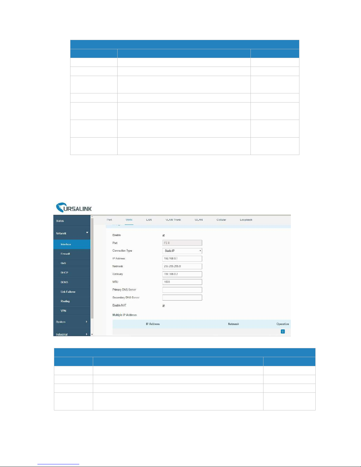
4.2.1.2 WAN
WAN port can be connected with Ethernet cable to get Internet access. It supports 3 connection types.
- Static IP: configure IP address, netmask and gateway for Ethernet WAN interface.
- DHCP Client: configure Ethernet WAN interface as DHCP Client to obtain IP address automatically.
- PPPoE: configure Ethernet WAN interface as PPPoE Client.
Figure 4-2-1-2
Page 34
UR52 & UR55 User Guide
34
WAN Setting
Item
Description
Default
Enable
Enable WAN function
Enable
Port
The port that is currently set as WAN port.
FE 0
Connection
Type
Select from "Static IP", "DHCP Client" and "PPPoE".
Static IP
MTU
Set the maximum transmission unit.
1500
Primary DNS
Server
Set the primary DNS.
Null
Secondary DNS
Server
Set the secondary DNS.
Null
Enable NAT
Enable or disable NAT function. When enabled, a
private IP can be translated to a public IP.
Enable
Table 4-2-1-4 WAN Parameters
1. Static IP Configuration
If the external network assigns a fixed IP for the WAN interface, user can select “Static IP” mode.
Figure 4-2-1-3
Static IP
Item
Description
Default
IP Address
Set the IP address which can access Internet. E.g. 192.168.1.2.
192.168.0.1
Netmask
Set the Netmask for WAN port.
255.255.255.0
Gateway
Set the gateway's IP address for WAN port.
192.168.0.2
Multiple IP
Address
Set the multiple IP addresses for WAN port.
Null
Table 4-2-1-5 Static Parameters
Page 35
UR52 & UR55 User Guide
35
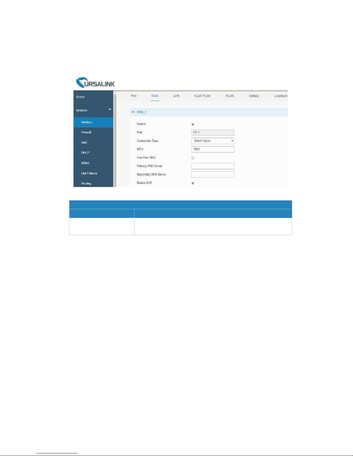
2. DHCP Client
If the external network has DHCP server enabled and has assigned IP addresses to the Ethernet WAN
interface, user can select “DHCP client” mode to obtain IP address automatically.
Figure 4-2-1-4
DHCP Client
Item
Description
Use Peer DNS
Obtain peer DNS automatically during PPP dialing. DNS is
necessary when visiting domain name.
Table 4-2-1-6 DHCP Client Parameters
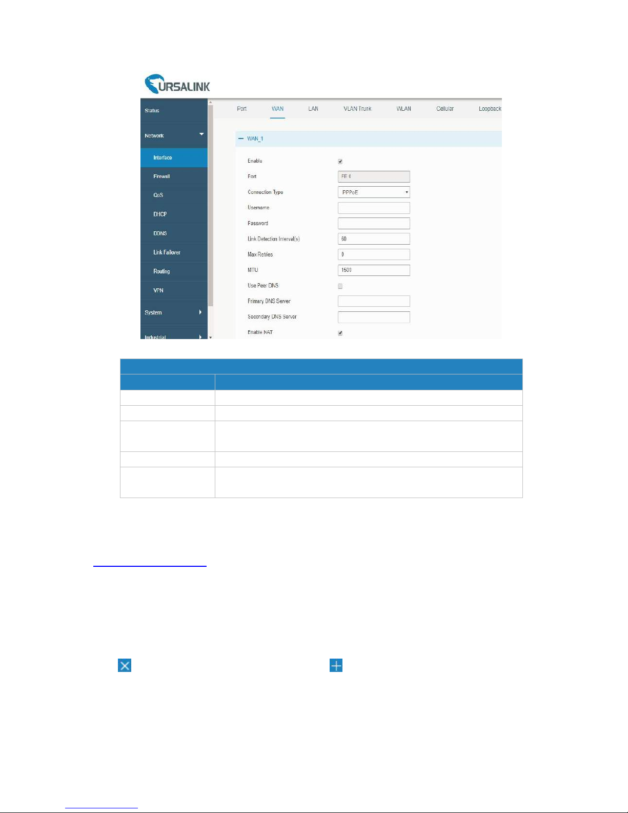
3. PPPoE
PPPoE refers to a point to point protocol over Ethernet. User has to install a PPPoE client on the basis of
original connection way. With PPPoE, remote access devices can get control of each user.
Page 36
UR52 & UR55 User Guide
36
Figure 4-2-1-5
PPPoE
Item
Description
Username
Enter the username provided by your Internet Service Provider (ISP).
Password
Enter the password provided by your Internet Service Provider (ISP).
Link Detection
Interval (s)
Set the heartbeat interval for link detection. Range: 1-600.
Max Retries
Set the maximum retry times after it fails to dial up. Range: 0-9.
Use Peer DNS
Obtain peer DNS automatically during PPP dialing. DNS is necessary
when visiting domain name.
Table 4-2-1-7 PPOE Parameters
Related Configuration Example
Ethernet WAN Connection
4.2.1.3 LAN
LAN setting is used for managing local area network devices which are connected to LAN ports of the
UR52/UR55, allowing each of them to access the Internet.
Click to delete the existing LAN port setting. Click to add a new LAN port.
Page 37
UR52 & UR55 User Guide
37
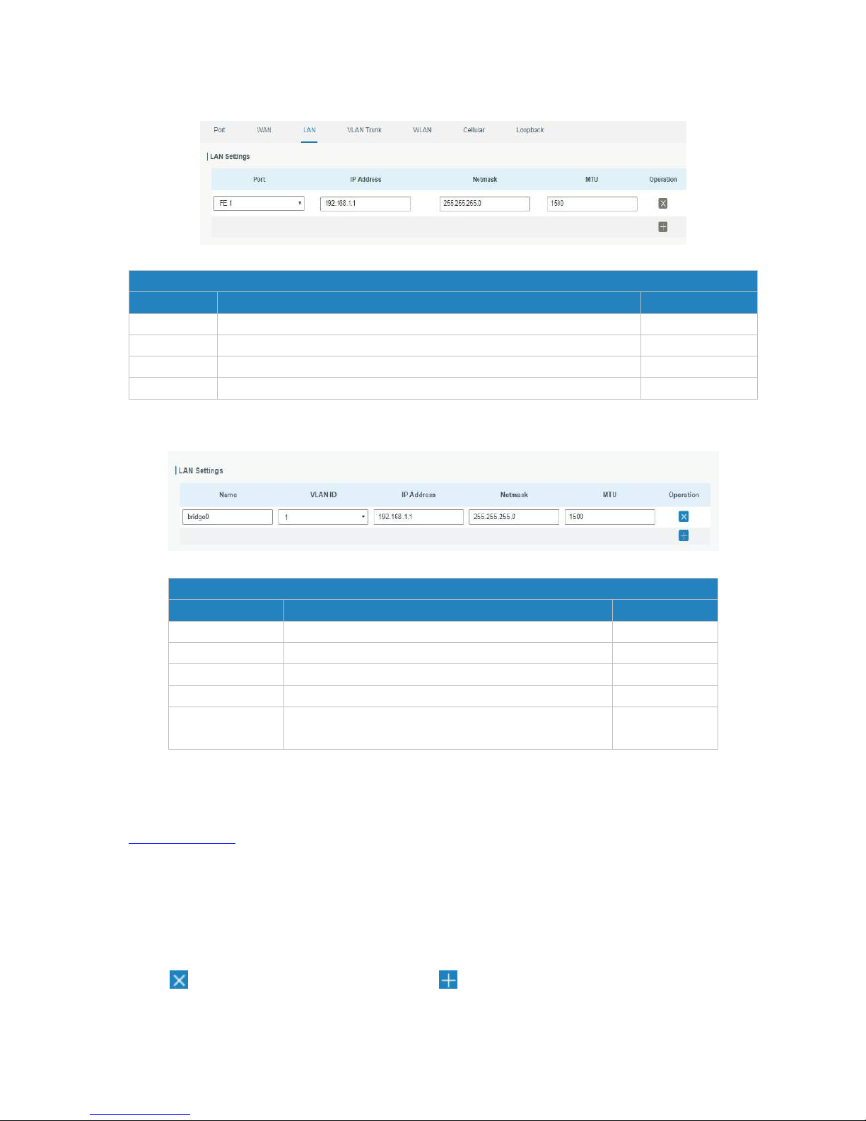
1. UR52
Figure 4-2-1-6
LAN
Item
Description
Default
Interface
Select LAN port.
FE 1
IP Address
Set IP address of LAN port.
192.168.1.1
Netmask
Set Netmask of LAN port.
255.255.255.0
MTU
Set the maximum transmission unit of LAN port. Range: 68-1500.
1500
Table 4-2-1-8
2. UR55
Figure 4-2-1-7
LAN
Item
Description
Default
Name
Set interface name of VLAN.
bridge0
VLAN ID
Select VLAN ID of the interface.
1
IP Address
Set IP address of LAN port.
192.168.1.1
Netmask
Set Netmask of LAN port.
255.255.255.0
MTU
Set the maximum transmission unit of LAN port.
Range: 68-1500.
1500
Table 4-2-1-9 LAN Parameters
Related Configuration Example
LAN Management
4.2.1.4 VLAN Trunk
VLAN is a kind of new data exchange technology that realizes virtual work groups by logically dividing the
LAN device into network segments.
Client to delete the current VLAN setting. Click to add a new VLAN port.
Page 38
UR52 & UR55 User Guide
38
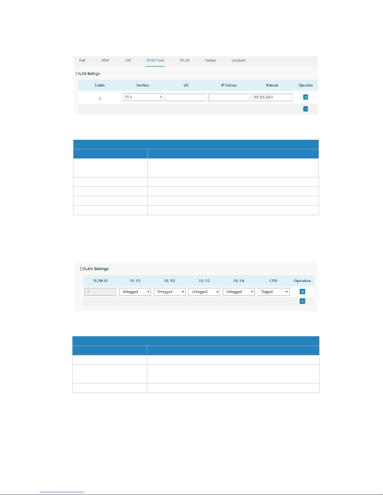
1. UR52
Figure 4-2-1-8
VLAN Trunk
Item
Description
Enable
The router can encapsulate or decapsulate the virtual LAN tag
when this function is enabled.
Interface
Select the VLAN interface from the LAN ports.
VID
Set the label ID of the VLAN. Range: 1-4094.
IP Address
Set VLAN port's IP address.
Netmask
Set VLAN port's netmask.
Table 4-2-1-10 VLAN Trunk Parameters
2. UR55
Figure 4-2-1-9
VLAN
Item
Description
VLAN ID
Set the label ID of the VLAN. Range: 1-4094.
FE 1/1 - FE 1/4
Select status from "Tagged", "Untagged" and "Close" for
Ethernet frame on trunk link.
CPU
Control communication between VLAN and other networks.
Table 4-2-1-11 VLAN Parameters
Page 39
UR52 & UR55 User Guide
39
4.2.1.5 WLAN (Only Applicable to Wi-Fi Version)
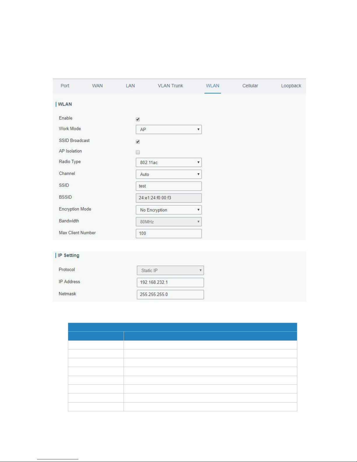
This section explains how to set the related parameters for Wi-Fi network. UR52/UR55 supports 802.11
b/g/n/ac, as AP or client mode. Wi-Fi is optional on UR52/UR55.
Figure 4-2-1-10
Figure 4-2-1-11
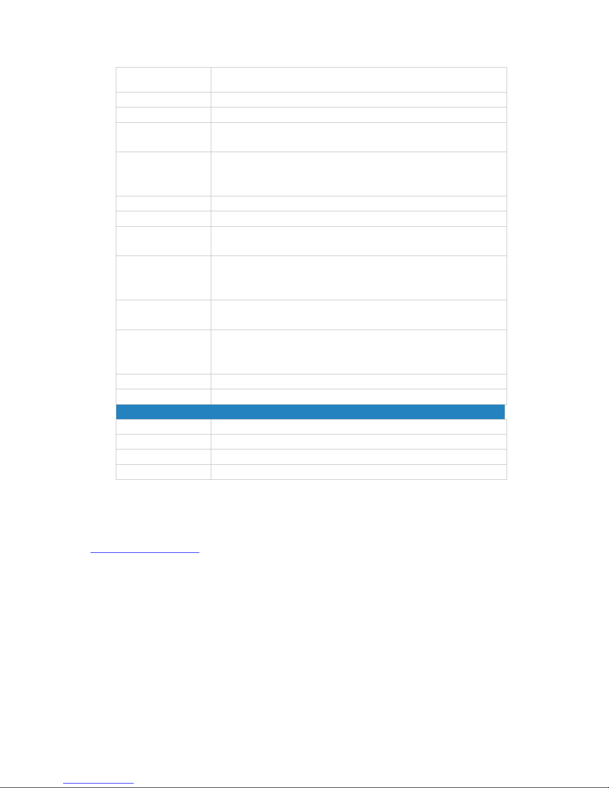
WLAN Settings
Item
Description
Enable
Enable/disable WLAN.
Work Mode
Select router's work mode. The options are "Client" and "AP".
Scan
Click "Scan" button to search the nearby access point.
SSID
Show SSID.
Channel
Show wireless channel.
Signal
Show wireless signal.
BSSID
Show the MAC address of the access point.
Security
Show the encryption mode.
Page 40
UR52 & UR55 User Guide
40
Frequency
Show the frequency of radio.
Join Network
Click the button to join the wireless network.
SSID
Fill in the SSID of the access point.
BSSID
Fill in the MAC address of the access point. Either SSID or BSSID can
be filled to joint the network.
Encryption Mode
Select encryption mode. The options are “No Encryption", “WEP
Open System" , “WEP Shared Key", “WPA-PSK", “WPA2-PSK" and
“WPA-PSK/WPA2-PSK".
Cipher
Select cipher. The options are “Auto", “AES", “TKIP" and “AES/TKIP".
Key
Fill the pre-shared key of WPA encryption.
Max Client Number
Set the maximum number of client to access when the router is
configured as AP.
SSID Broadcast
When SSID broadcast is disabled, other wireless devices can't not
find the SSID, and users have to enter the SSID manually to access
to the wireless network.
AP Isolation
When AP isolation is enabled, all users which access to the AP are
isolated without communication with each other.
Radio Type
Select Radio type. The options are “802.11b (2.4 GHz)", “802.11g
(2.4 GHz)", “802.11n (2.4 GHz)”, “802.11n (5 GHz)" and "802.11ac (5
GHz).
Channel
Select wireless channel. The options are "Auto", "1", "2"......"13".
Bandwidth
Select bandwidth. The options are "20MHz" and "40MHz".
IP Setting
Protocol
Set the IP address in wireless network.
IP Address
Set the IP address in wireless network.
Netmask
Set the netmask in wireless network.
Gateway
Set the gateway in wireless network.
Table 4-2-1-12 WLAN Parameters
Related Topic
Wi-Fi Application Example
4.2.1.6 Cellular
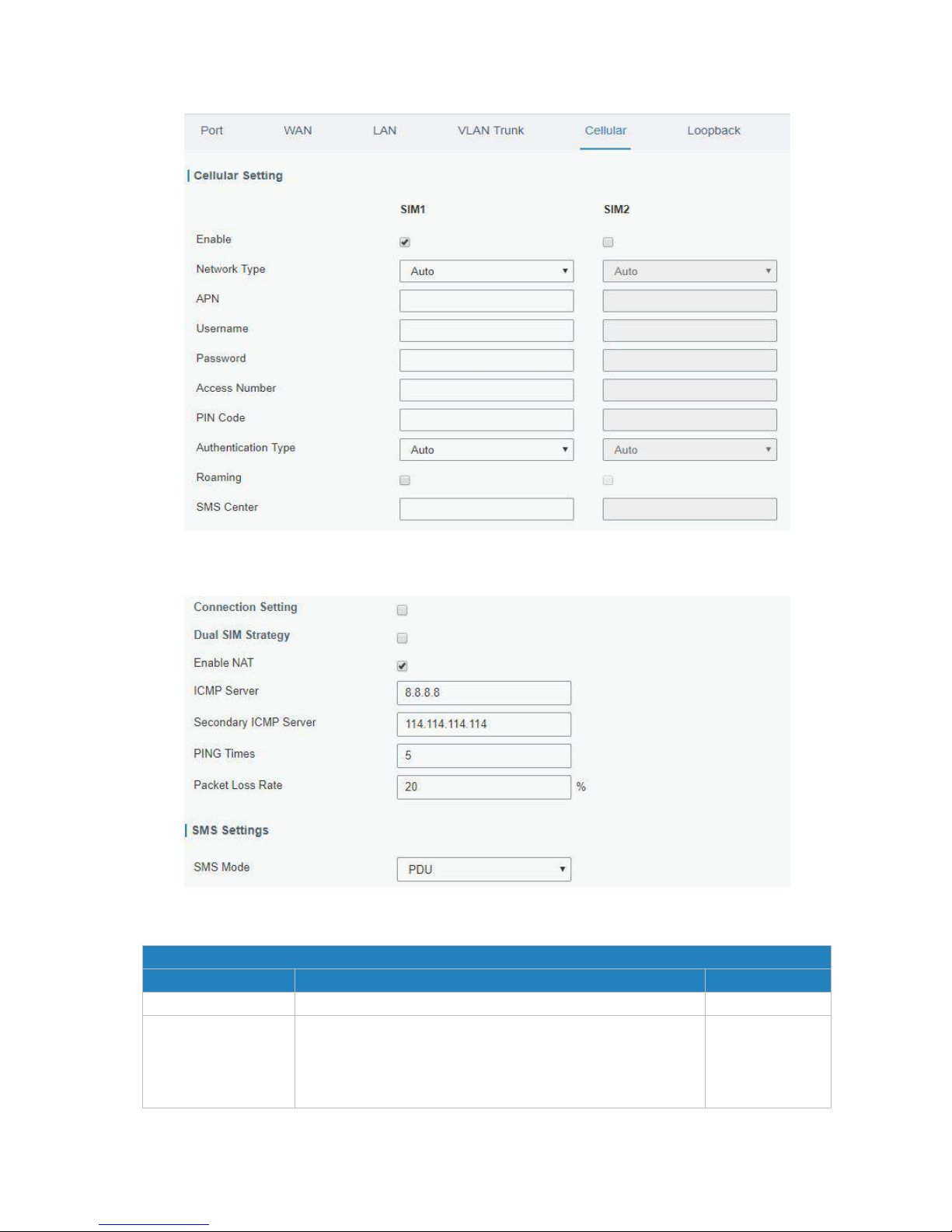
This section explains how to set the related parameters for cellular network. The UR52/UR55 cellular
router has two cellular interfaces, namely SIM1 and SIM2. Only one cellular interface is active at one time.
If both cellular interfaces are enabled, then SIM1 interface takes precedence by default.
A typical use case would be to have SIM1 configured as the primary cellular interface and SIM2 as a
backup. If the UR52/UR55 cannot connect to the network via SIM1, it will automatically fail over to SIM2.
Page 41
UR52 & UR55 User Guide
41
Figure 4-2-1-13
Figure 4-2-1-14
General Settings
Item
Description
Default
Enable
Check the option to enable the corresponding SIM card.
Enable
Network Type
Select from "Auto", "4G First", "4G Only", "3G First", "3G
Only", "2G Frist", and "2G Only".
Auto: connect to the network with the strongest signal
automatically.
Auto
Page 42

UR52 & UR55 User Guide
42
4G First: 4G network takes precedence.
4G Only: connect to 4G network only.
And so on.
APN
Enter the Access Point Name for cellular dial-up connection
provided by local ISP.
Null
Username
Enter the username for cellular dial-up connection provided
by local ISP.
Null
Password
Enter the password for cellular dial-up connection provided
by local ISP.
Null
Access Number
Enter the dial-up center NO. For cellular dial-up connection
provided by local ISP.
Null
PIN Code
Enter a 4-8 characters PIN code to unlock the SIM.
Null
Authentication Type
Select from "Auto", "PAP", "CHAP", "MS-CHAP", and
"MS-CHAPv2".
Auto
Roaming
Enable or disable roaming.
Disable
SMS Center
Enter the local SMS center number for storing, forwarding,
converting and delivering SMS message.
Null
Enable NAT
Enable or disable NAT function.
Enable
ICMP Server
Set the ICMP detection server's IP address.
8.8.8.8
Secondary ICMP
Server
Set the secondary ICMP detection server's IP address.
114.114.114.114
PING Times
Set PING packet numbers in each ICMP detection.
5
Packet Loss Rate
Set packet loss rate in each ICMP detection. ICMP detection
fails when the preset packet loss rate is exceeded.
20
Table 4-2-1-13 Cellular Parameters
Page 43
UR52 & UR55 User Guide
43
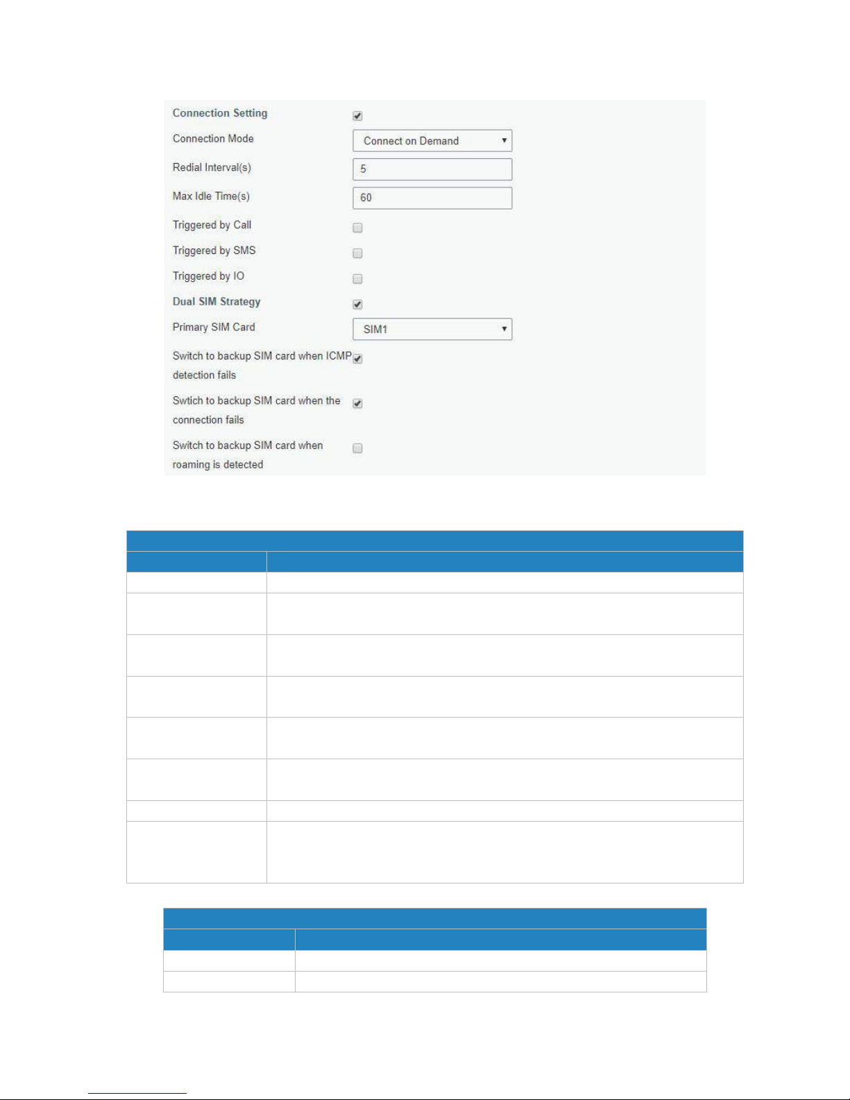
Figure 4-2-1-15
Connection Mode
Item
Description
Connection Mode
Select from "Always Online" and "Connect on Demand".
Connect on Demand
"Connect on Demand" includes "Triggered by Call", "Triggered by SMS", and
"Triggered by IO".
Triggered by Call
The router will switch from offline mode to cellular network mode
automatically when it receives a call from the specific phone number.
Call Group
Select a call group for call trigger. Go to "System > General > Phone" to set up
phone group.
Triggered by SMS
The router will switch from offline mode to cellular network mode
automatically when it receives a specific SMS from the specific mobile phone.
SMS Group
Select an SMS group for trigger. Go to "System > General > Phone" to set up
SMS group.
SMS Text
Fill in the SMS content for triggering.
Triggered by IO
The router will switch from offline mode to cellular network mode
automatically when the DI status is changed. Go to "Industrial > I/O > DI" to
configure trigger condition.
Table 4-2-1-14 Cellular Parameters
Dual SIM Strategy
Item
Description
Current SIM Card
Select between "SIM1" and "SIM2" as a current SIM card used.
Switch to backup
The router will switch to the backup SIM card when packet loss rate
Page 44
UR52 & UR55 User Guide
44
SIM card when
ICMP detection fails
in IMCP detection exceeds the preset value.
Switch to backup
SIM card when the
connection fails
The router will switch to the backup SIM card when the primary
one fails to connect with cellular network.
Switch to backup
SIM card when
roaming is detected
The router will switch to the backup SIM card when the primary
one is roaming.
Table 4-2-1-15 Cellular Parameters
Related Topics
Cellular Network Connection
Dual SIM Failover Application Example
WAN Failover Application Example
Phone Group
DI Setting
4.2.1.7 Loopback
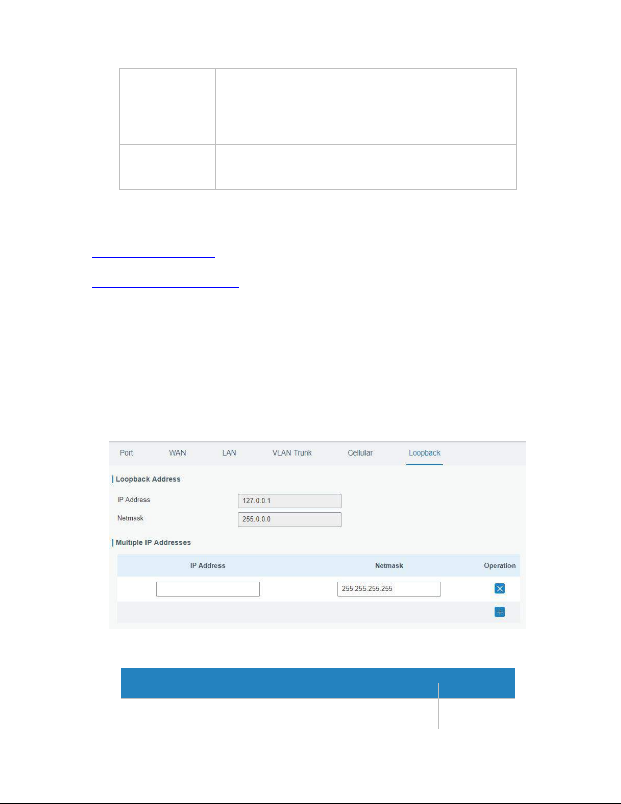
Loopback interface is used for replacing router's ID as long as it is activated. When the interface is DOWN,
the ID of the router has to be selected again which leads to long convergence time of OSPF. Therefore,
Loopback interface is generally recommended as the ID of the router.
Loopback interface is a logic and virtual interface on router. Under default conditions, there's no loopback
interface on router, but it can be created as required.
Figure 4-2-1-16
Loopback
Item
Description
Default
IP Address
Unalterable
127.0.0.1
Netmask
Unalterable
255.0.0.0
Page 45
UR52 & UR55 User Guide
45
Multiple IP
Addresses
Apart from the IP above, user can configure
other IP addresses.
Null
Table 4-2-1-16 Loopback Parameters
4.2.2 Firewall
This section describes how to set the firewall parameters, including ACL, DMZ, Port Mapping and MAC
Binding.
The firewall implements corresponding control of data flow at entry direction (from Internet to local area
network) and exit direction (from local area network to Internet) according to the content features of
packets, such as protocol style, source/destination IP address, etc. It ensures that the router operate in a
safe environment and host in local area network.
4.2.2.1 ACL
Access control list, also called ACL, implements permission or prohibition of access for specified network
traffic (such as the source IP address) by configuring a series of matching rules so as to filter the network
interface traffic. When router receives packet, the field will be analyzed according to the ACL rule applied
to the current interface. After the special packet is identified, the permission or prohibition of
corresponding packet will be implemented according to preset strategy.
The data package matching rules defined by ACL can also be used by other functions requiring flow
distinction.
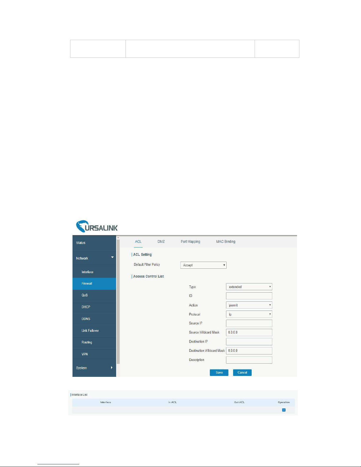
Figure 4-2-2-1
Figure 4-2-2-2
Page 46
UR52 & UR55 User Guide
46
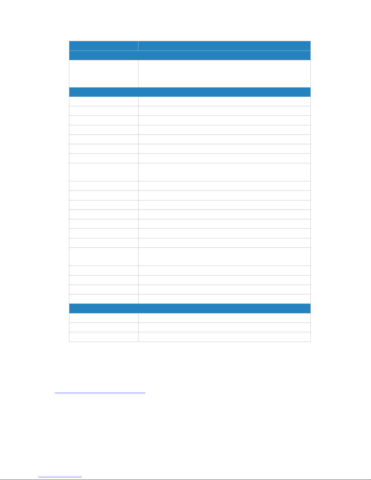
Item
Description
ACL Setting
Default Filter Policy
Select from "Accept" and "Deny".
The packets which are not included in the access control list will
be processed by the default filter policy.
Access Control List
Type
Select type from "Extended" and "Standard".
ID
User-defined ACL number. Range: 1-199.
Action
Select from "Permit" and "Deny".
Protocol
Select protocol from "ip", "icmp", "tcp", "udp", and "1-255".
Source IP
Source network address (leaving it blank means all).
Source Wildcard Mask
Wildcard mask of the source network address.
Destination IP
Destination network address (0.0.0.0 means all).
Destination Wildcard
Mask
Wildcard mask of destination address.
Description
Fill in a description for the groups with the same ID.
ICMP Type
Enter the type of ICMP packet. Range: 0-255.
ICMP Code
Enter the code of ICMP packet. Range: 0-255.
Source Port Type
Select source port type, such as specified port, port range, etc.
Source Port
Set source port number. Range: 1-65535.
Start Source Port
Set start source port number. Range: 1-65535.
End Source Port
Set end source port number. Range: 1-65535.
Destination Port Type
Select destination port type, such as specified port, port range,
etc.
Destination Port
Set destination port number. Range: 1-65535.
Start Destination Port
Set start destination port number. Range: 1-65535.
End Destination Port
Set end destination port number. Range: 1-65535.
More Details
Show information of the port.
Interface List
Interface
Select network interface for access control.
In ACL
Select a rule for incoming traffic from ACL ID.
Out ACL
Select a rule for outgoing traffic from ACL ID.
Table 4-2-2-1 ACL Parameters
Related Configuration Example
Access Control Application Example
Page 47
UR52 & UR55 User Guide
47
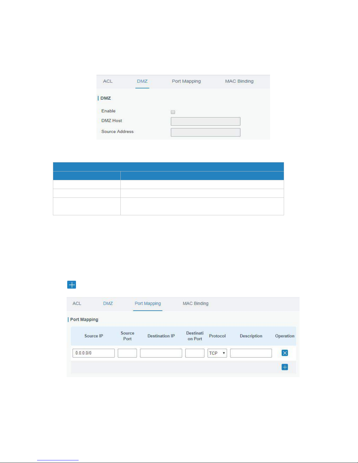
4.2.2.2 DMZ
DMZ is a host within the internal network that has all ports exposed, except those forwarded ports in port
mapping.
Figure 4-2-2-3
DMZ
Item
Description
Enable
Enable or disable DMZ.
DMZ Host
Enter the IP address of the DMZ host on the internal network.
Source Address
Set the source IP address which can access to DMZ host.
"0.0.0.0/0" means any address.
Table 4-2-2-2 DMZ Parameters
4.2.2.3 Port Mapping
Port mapping is an application of network address translation (NAT) that redirects a communication
request from the combination of an address and port number to another while the packets are traversing
a network gateway such as a router or firewall.
Click to add a new port mapping rules.
Figure 4-2-2-4
Page 48
UR52 & UR55 User Guide
48
Port Mapping
Item
Description
Source IP
Specify the host or network which can access local IP address.
0.0.0.0/0 means all.
Source Port
Enter the TCP or UDP port from which incoming packets are
forwarded. Range: 1-65535.
Destination IP
Enter the IP address that packets are forwarded to after being
received on the incoming interface.
Destination Port
Enter the TCP or UDP port that packets are forwarded to after
being received on the incoming port(s). Range: 1-65535.
Protocol
Select from "TCP" and "UDP" as your application required.
Description
The description of this rule.
Table 4-2-2-3 Port Mapping Parameters
Related Configuration Example
NATApplication Example
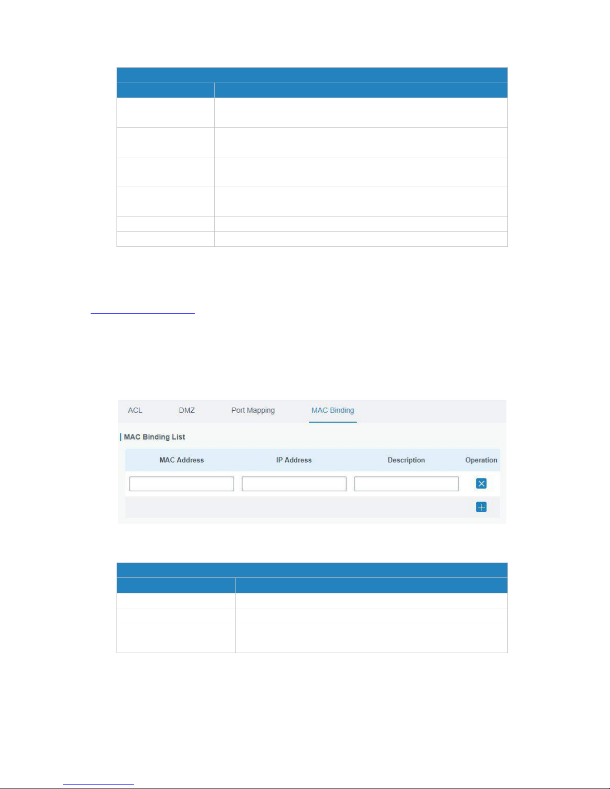
4.2.2.4 MAC Binding
MAC Binding is used for specifying hosts by matching MAC addresses and IP addresses that are in the list
of allowed outer network access.
Figure 4-2-2-5
MAC Binding List
Item
Description
MAC Address
Set the binding MAC address.
IP Address
Set the binding IP address.
Description
Fill in a description for convenience of recording the meaning
of the binding rule for each piece of MAC-IP.
Table 4-2-2-4 MAC Binding Parameters
Page 49

UR52 & UR55 User Guide
49
4.2.3 QoS
Quality of service (QoS) refers to traffic prioritization and resource reservation control mechanisms rather
than the achieved service quality. QoS is engineered to provide different priority for different applications,
users, data flows, or to guarantee a certain level of performance to a data flow.
4.2.3.1 QoS (Download/Upload)
Figure 4-2-3-1
QoS
Item
Description
Download/Upload
Enable
Enable or disable QoS.
Default Class
Select default class from Service Class list.
Download/Upload
Bandwidth Capacity
The download/upload bandwidth capacity of the network that
the router is connected with, in kbps. Range: 1-8000000.
Service Classes
Name
Give the service class a descriptive name.
Percent (%)
The amount of bandwidth that this class should be guaranteed
in percentage. Range: 0-100.
Max BW(kbps)
The maximum bandwidth that this class is allowed to
consume, in kbps. The value should be less than the
"Download/Upload Bandwidth Capacity".
Min BW(kbps)
The minimum bandwidth that can be guaranteed for the class,
in kbps. The value should be less than the "MAX BW" value.
Classification Rules
Item
Description
Page 50
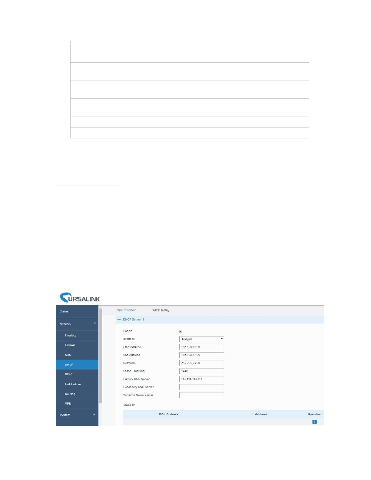
UR52 & UR55 User Guide
50
Name
Give the rule a descriptive name.
Source IP
Source address of flow control (leaving it blank means any).
Source Port
Source port of flow control. Range: 0-65535 (leaving it blank
means any).
Destination IP
Destination address of flow control (leaving it blank means
any).
Destination Port
Destination port of flow control. Range: 0-65535 (leaving it
blank means any).
Protocol
Select protocol from "ANY", "TCP", "UDP", "ICMP", and "GRE".
Service Class
Set service class for the rule.
Table 4-2-3-1 QoS (Download/Upload) Parameters
Related Configuration Example
Related Application Example
QoS Application Example
4.2.4 DHCP
DHCP adopts Client/Server communication mode. The Client sends configuration request to the Server
which feeds back corresponding configuration information and distributes IP address to the Client so as to
achieve the dynamic configuration of IP address and other information.
4.2.4.1 DHCP Server
The UR52/UR55 can be set as a DHCP server to distribute IP address when a host logs on and ensures
each host is supplied with different IP addresses. DHCP Server has simplified some previous network
management tasks requiring manual operations to the largest extent.
Figure 4-2-4-1
Page 51
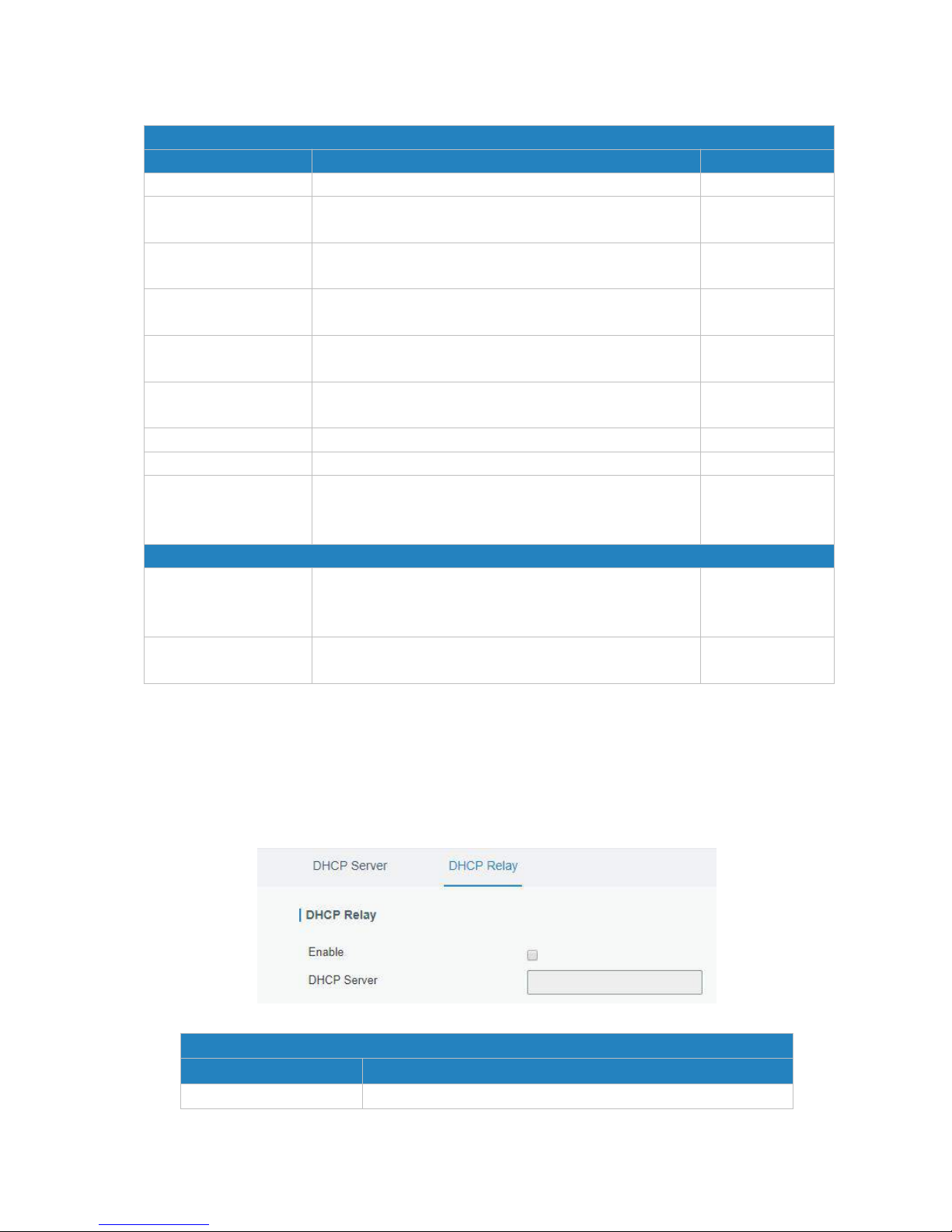
UR52 & UR55 User Guide
51
Table 4-2-4-1 DHCP Server Parameters
4.2.4.2 DHCP Relay
The UR52/UR55 can be set as DHCP Relay to provide a relay tunnel to solve the problem that DHCP Client
and DHCP Server are not in the same subnet.
Figure 4-2-4-2
DHCP Relay
Item
Description
Enable
Enable or disable DHCP relay.
DHCP Server
Item
Description
Default
Enable
Enable or disable DHCP server.
Enable
Interface
Select interface, e.g. FE1.
FE1 for UR52;
bridge0 for UR55
Start Address
Define the beginning of the pool of IP addresses which
will be leased to DHCP clients.
192.168.1.100
End Address
Define the end of the pool of IP addresses which will be
leased to DHCP clients.
192.168.1.199
Netmask
Define the subnet mask of IP address obtained by DHCP
clients from DHCP server.
255.255.255.0
Lease Time (Min)
Set the lease time on which the client can use the IP
address obtained from DHCP server. Range: 1-10080.
1440
Primary DNS Server
Set the primary DNS server.
114.114.114.114
Secondary DNS Server
Set the secondary DNS server.
Null
Windows Name Server
Define the Windows Internet Naming Service obtained
by DHCP clients from DHCP sever. Generally you can
leave it blank.
Null
Static IP
MAC Address
Set a static and specific MAC address for the DHCP client
(it should be different from other MACs so as to avoid
conflict).
Null
IP Address
Set a static and specific IP address for the DHCP client (it
should be outside of the DHCP range).
Null
Page 52
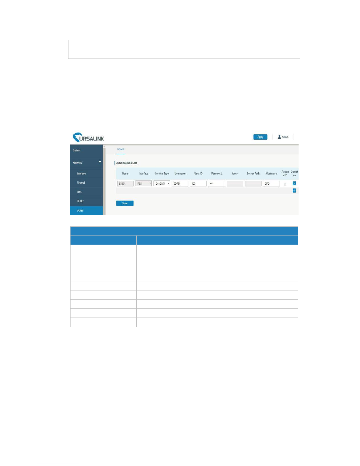
UR52 & UR55 User Guide
52
DHCP Server
Set DHCP server, up to 10 servers can be configured; separate
them by blank space or ",".
Table 4-2-4-2 DHCP Relay Parameters
4.2.5 DDNS
Dynamic DNS (DDNS) is a method that automatically updates a name server in the Domain Name System,
which allows user to alias a dynamic IP address to a static domain name.
DDNS serves as a client tool and needs to coordinate with DDNS server. Before starting configuration, user
shall register on a website of proper domain name provider and apply for a domain name.
Figure 4-2-5-1
DDNS
Item
Description
Name
Give the DDNS a descriptive name.
Interface
Set interface bundled with the DDNS.
Service Type
Select the DDNS service provider.
Username
Enter the username for DDNS register.
User ID
Enter User ID of the custom DDNS server.
Password
Enter the password for DDNS register.
Server
Enter the name of DDNS server.
Hostname
Enter the hostname for DDNS.
Append IP
Append your current IP to the DDNS server update path.
Table 4-2-5-1 DDNS Parameters
4.2.6 Link Failover
This section describes how to configure link failover strategies, including VRRP strategies and WAN
failover strategies between Ethernet WAN and cellular.
Configuration Steps
1. Define one or more SLA operations (ICMP probe).
2. Define one or more track objects to track the status of SLA operation.
3. Define applications associated with track objects, such as VRRP, WAN failover or static routing.
Page 53
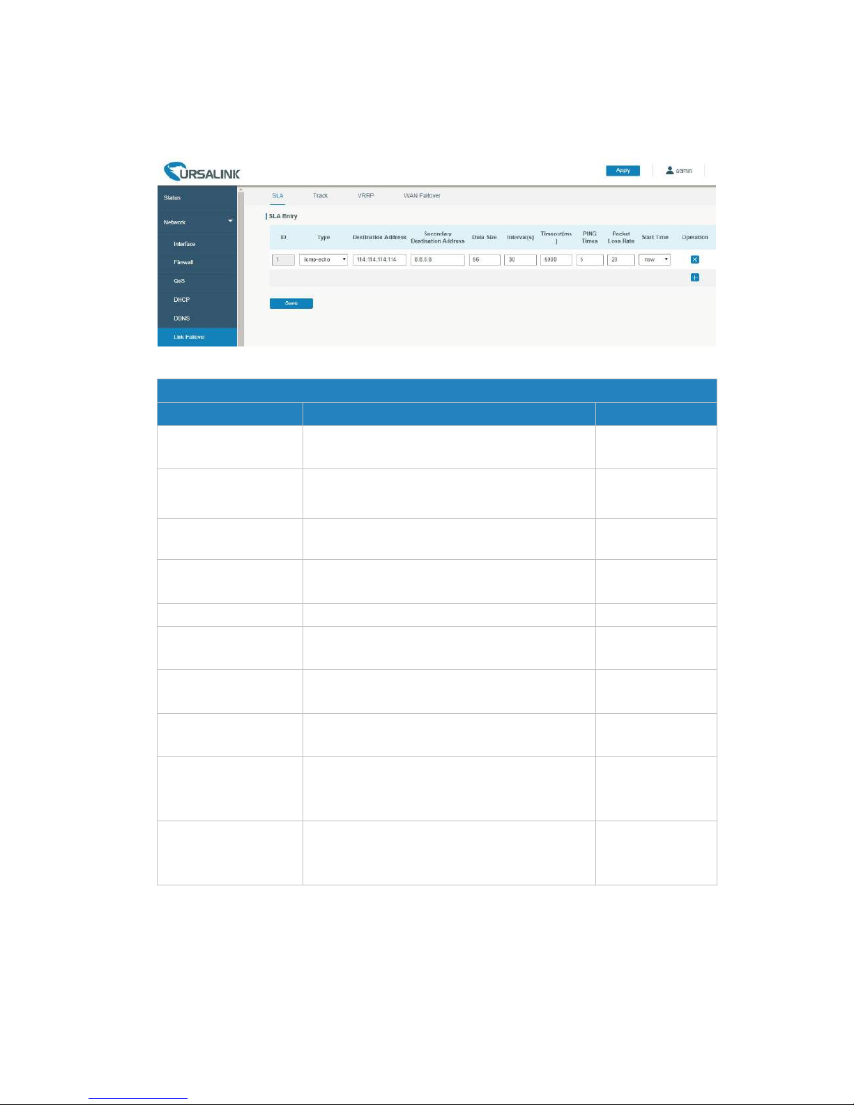
UR52 & UR55 User Guide
53
4.2.6.1 SLA
SLA setting is used for configuring link probe method. The default probe type is ICMP.
Figure 4-2-6-1
SLA
Item
Description
Default
ID
SLA index. Up to 10 SLA settings can be added.
Range: 1-10.
1
Type
ICMP-ECHO is the default type to detect if the
link is alive.
icmp-echo
Destination Address
The detected IP address.
114.114.114.114
Secondary Destination
Address
The secondary detected IP address.
8.8.8.8
Data Size
User-defined data size. Range: 0-1000.
56
Interval (s)
User-defined detection interval. Range:
1-608400.
30
Timeout (ms)
User-defined timeout for response to determine
ICMP detection failure. Range: 1-300000.
5000
PING Times
Define PING packet numbers in each SLA probe.
Range: 1-1000.
5
Packet Loss Rate
Define packet loss rate in each SLA probe. SLA
probe fails when the preset packet loss rate is
exceeded.
20
Start Time
Detection start time; select from "Now" and
blank character. Blank character means this SLA
detection doesn't start.
now
Table 4-2-6-1 SLA Parameters
4.2.6.2 Track
Track setting is designed for achieving linkage among SLA module, Track module and Application module.
Track setting is located between application module and SLA module with main function of shielding the
differences of various SLA modules and providing unified interfaces for application module.
Page 54
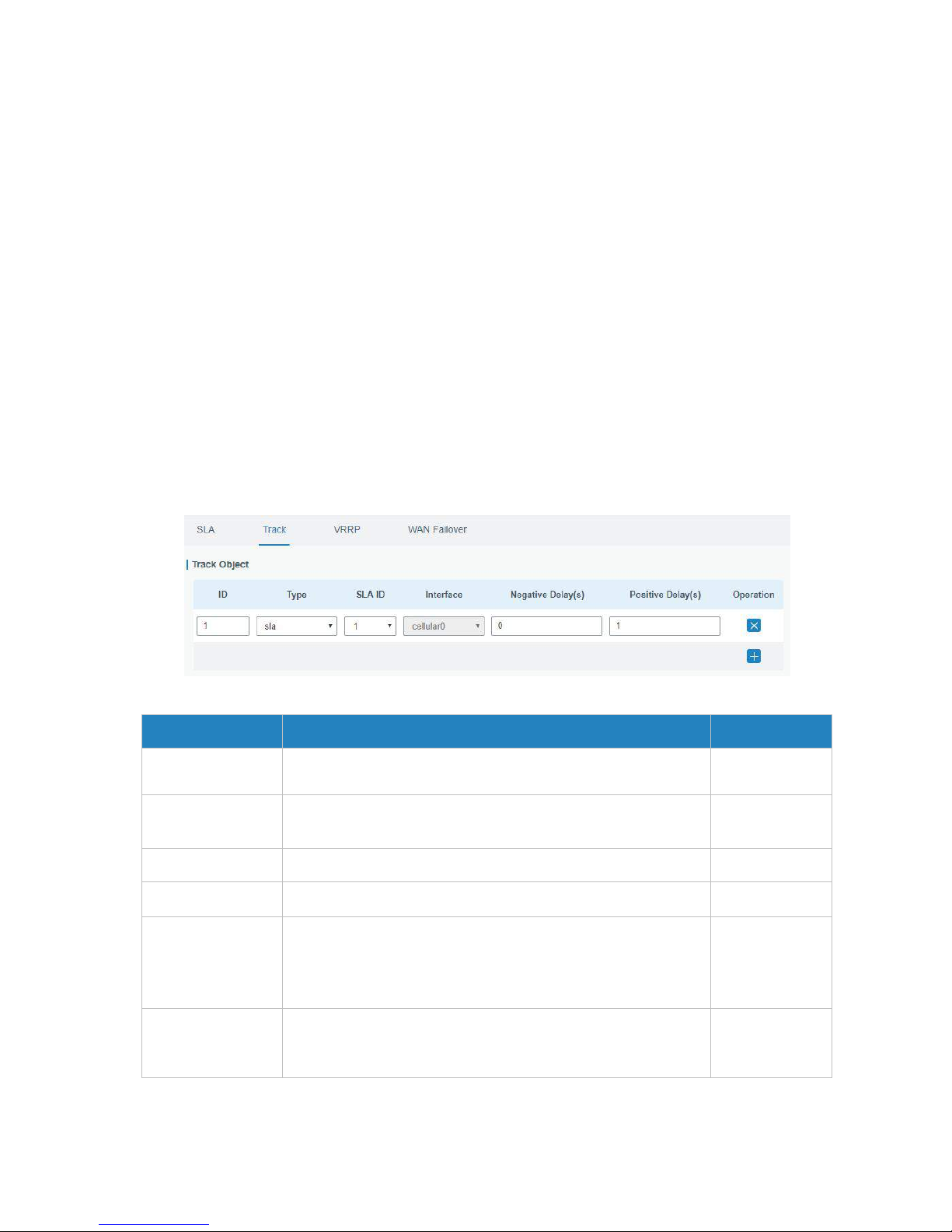
UR52 & UR55 User Guide
54
Linkage between Track Module and SLA module
Once you complete the configuration, the linkage relationship between Track module and SLA module will
be established. SLA module is used for detection of link status, network performance and notification of
Track module. The detection results help track status change timely.
- For successful detection, the corresponding track item is Positive.
- For failed detection, the corresponding track item is Negative.
Linkage between Track Module and Application Module
After configuration, the linkage relationship between Track module and application module will be
established. When any change occurs in track item, a notification that requires corresponding treatment
will be sent to Application module.
Currently, the application modules like VRRP, WAN failover and static routing can get linkage with track
module.
If it sends an instant notification to Application module, the communication may be interrupted in some
circumstances due to routing's failure like timely restoration or other reasons. Therefore, user can set up a
period of time to delay notifying application module when the track item status changes.
Figure 4-2-6-2
Item
Description
Default
Index
Track index. Up to 10 track settings can be configured. Range:
1-10.
1
Type
The options are "sla" and "interface".
SLA
SLA ID
Defined SLA ID.
1
Interface
Select the interface whose status will be detected.
cellular0
Negative Delay (s)
When interface is down or SLA probing fails, it will wait
according to the time set here before actually changing its
status to Down. Range: 0-180 (0 refers to immediate
switching).
0
Positive Delay (s)
When failure recovery occurs, it will wait according to the time
set here before actually changing its status to Up. Range:
0-180 (0 refers to immediate switching).
1
Table 4-2-6-2 Track Parameters
Page 55
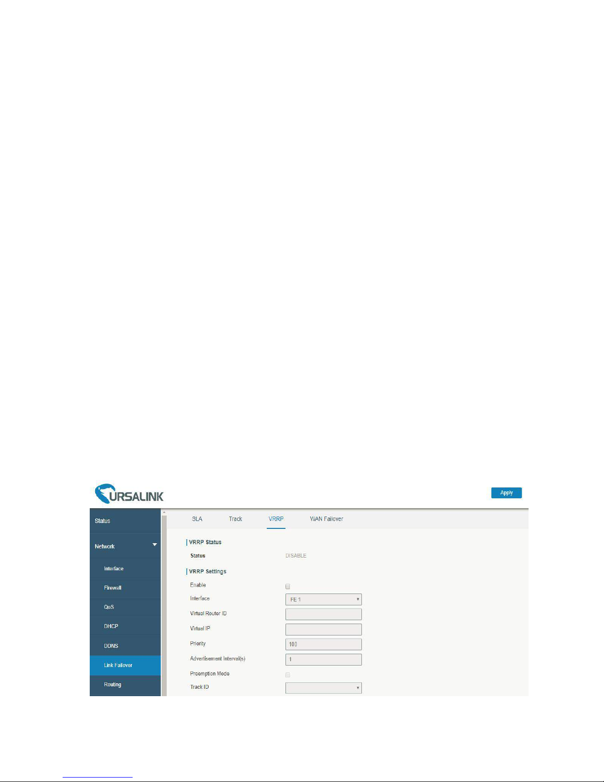
UR52 & UR55 User Guide
55
4.2.6.3 VRRP
The Virtual Router Redundancy Protocol (VRRP) is a computer networking protocol that provides
automatic assignment of available Internet Protocol (IP) routers for participating hosts. This increases the
availability and reliability of routing paths via automatic default gateway selections in an IP sub-network.
Increasing the number of exit gateway is a common method for improving system reliability. VRRP adds a
group of routers that undertake gateway function into a backup group so as to form a virtual router. The
election mechanism of VRRP will decide which router undertakes the forwarding task, and the host in LAN
is only required to configure the default gateway for the virtual router.
In VRRP, routers need to be aware of failures in the virtual master router. To achieve this, the virtual
master router sends out multicast “alive” announcements to the virtual backup routers in the same VRRP
group.
The VRRP router who has the highest number will become the virtual master router. The VRRP router
number ranges from 1 to 255 and usually we use 255 for the highest priority and 100 for backup.
If the current virtual master router receives an announcement from a group member (Router ID) with a
higher priority, then the latter will pre-empt and become the virtual master router.
VRRP has the following characteristics:
- The virtual router with an IP address is known as the Virtual IP address. For the host in LAN, it is only
required to know the IP address of virtual router, and set it as the address of the next hop of the
default route.
- The network Host communicates with the external network through this virtual router.
- A router will be selected from the set of routers based on its priority to undertake the gateway
function. Other routers will be used as backup routers to perform the duties of gateway for the
gateway router in the case of any malfunction, so as to guarantee uninterrupted communication
between the host and external network.
When interface connected with the uplink is at the state of Down or Removed, the router actively lowers
its priority so that priority of other routers in the backup group will be higher. Thus the router with the
highest priority becomes the gateway for the transmission task.
Figure 4-2-6-3
Page 56

UR52 & UR55 User Guide
56
VRRP
Item
Description
Default
Enable
Enable or disable VRRP.
Disable
Interface
Select the interface of Virtual Router.
None
Virtual Router ID
User-defined Virtual Router ID. Range: 1-255.
None
Virtual IP
Set the IP address of Virtual Router.
None
Priority
The VRRP priority range is 1-254 (a bigger number indicates a
higher priority). The router with higher priority will be more
likely to become the gateway router.
100
Advertisement Interval (s)
Heartbeat package transmission time interval between
routers in the virtual ip group. Range: 1-255.
1
Preemption Mode
If the router works in the preemption mode, once it finds that
its own priority is higher than that of the current gateway
router, it will send VRRP notification package, resulting in
re-election of gateway router and eventually replacing the
original gateway router. Accordingly, the original gateway
router will become a Backup router.
Disable
Track ID
Trace detection, select the defined track ID or blank
character.
None
Table 4-2-6-3 VRRP Parameters
Note: for UR55, if you select “bridge0” as interface, you must select a track ID, otherwise VRRP status
won’t show correctly.
Related Configuration Example
VRRP Application Example
4.2.6.4 WAN Failover
WAN failover refers to failover between Ethernet WAN interface and cellular interface. When service
transmission can’t be carried out normally due to malfunction of a certain interface or lack of bandwidth,
the rate of flow can be switched to backup interface quickly. Then the backup interface will carry out
service transmission and share network flow so as to improve reliability of communication of data
equipment.
When link state of main interface is switched from up to down, system will have the pre-set delay works
instead of switching to link of backup interface immediately. Only if the state of main interface is still
down after delay, will the system switch to link of backup interface. Otherwise, system will remain
unchanged.
Page 57
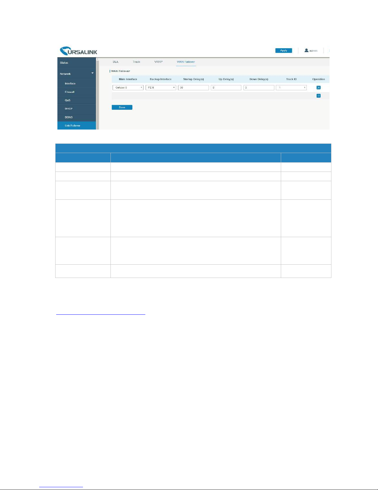
UR52 & UR55 User Guide
57
Figure 4-2-6-4
WAN Failover
Parameters
Description
Default
Main Interface
Select a link interface as the main link.
Cellular0
Backup Interface
Select a link interface as the backup link.
FE0
Startup Delay (s)
Set how long to wait for the startup tracking detection policy
to take effect. Range: 0-300.
3
Up Delay (s)
When the primary interface switches from failed detection to
successful detection, switching can be delayed based on the
set time. Range: 0-180 (0 refers to immediate switching).
0
Down Delay (s)
When the primary interface switches from successful detection
to failed detection, switching can be delayed based on the set
time. Range: 0-180 (0 refers to immediate switching).
0
Track ID
Track detection, select the defined track ID.
1
Table 4-2-6-4 WAN Failover Parameters
Related Configuration Example
WAN Failover Application Example
4.2.7 Routing
4.2.7.1 Static Routing
A static routing is a manually configured routing entry. Information about the routing is manually entered
rather than obtained from dynamic routing traffic. After setting static routing, the package for the
specified destination will be forwarded to the path designated by user.
Page 58
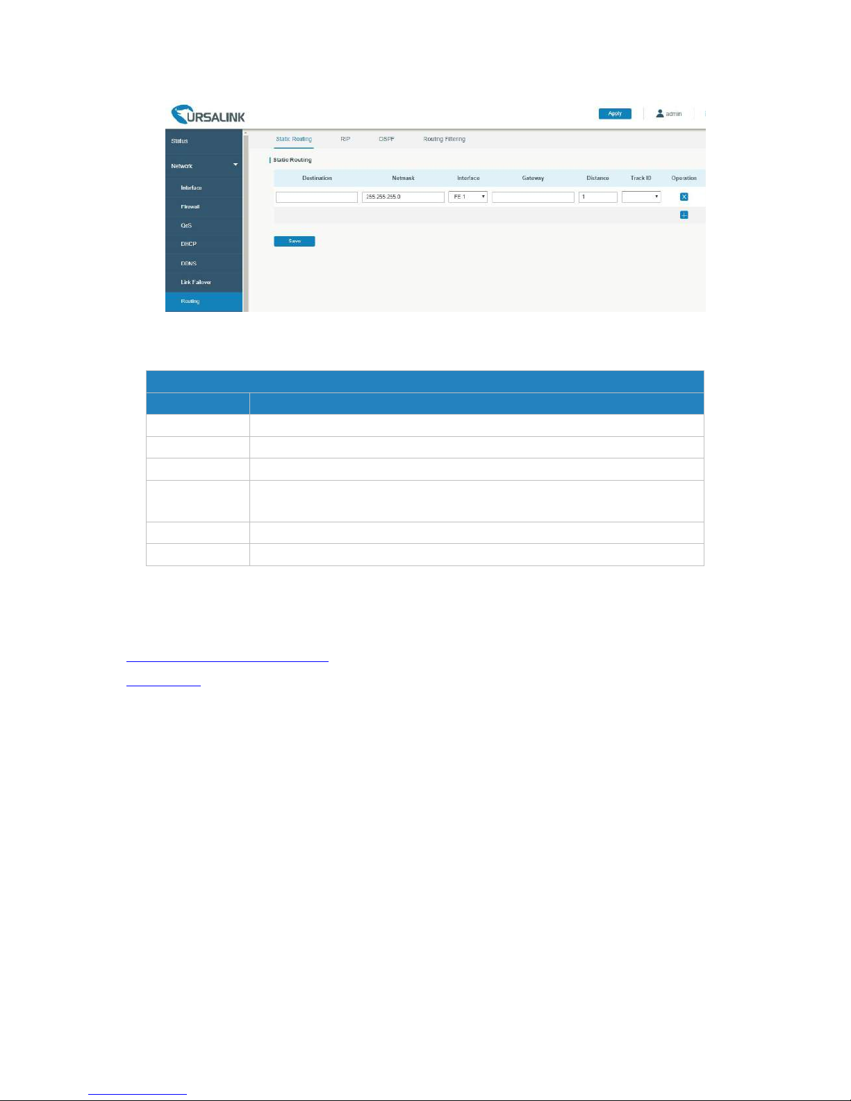
UR52 & UR55 User Guide
58
Figure 4-2-7-1
T
Table 4-2-7-1 Static Routing Parameters
Related Topics
Static Routing Application Example
Track Setting
4.2.7.2 RIP
RIP is mainly designed for small networks. RIP uses Hop Count to measure the distance to the destination
address, which is called Metric. In RIP, the hop count from the router to its directly connected network is 0
and the hop count of network to be reached through a router is 1 and so on. In order to limit the
convergence time, the specified metric of RIP is an integer in the range of 0 - 15 and the hop count larger
than or equal to 16 is defined as infinity, which means that the destination network or host is unreachable.
Because of this limitation, the RIP is not suitable for large-scale networks. To improve performance and
prevent routing loops, RIP supports split horizon function. RIP also introduces routing obtained by other
routing protocols.
Each router that runs RIP manages a routing database, which contains routing entries to reach all
reachable destinations.
Static Routing
Item
Description
Destination
Enter the destination IP address.
Netmask
Enter the subnet mask of destination address.
Interface
The interface through which the data can reach the destination address.
Gateway
IP address of the next router that will be passed by before the input data
reaches the destination address.
Distance
Priority, smaller value refers to higher priority. Range: 1-255.
Track ID
Track detection, select the defined track ID. You can leave it blank.
Page 59
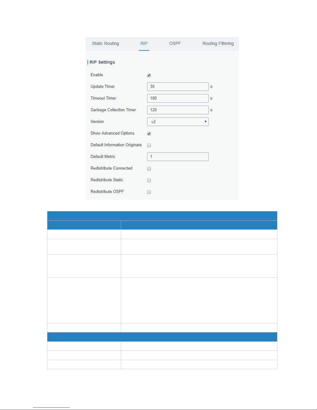
UR52 & UR55 User Guide
59
Figure 4-2-7-2
RIP
Item
Description
Enable
Enable or disable RIP.
Update Timer
It defines the interval to send routing updates. Range:
5-2147483647, in seconds.
Timeout Timer
It defines the routing aging time. If no update package on a routing is
received within the aging time, the routing's Routing Cost in the
routing table will be set to 16. Range: 5-2147483647, in seconds.
Garbage Collection Timer
It defines the period from the routing cost of a routing becomes 16
to it is deleted from the routing table. In the time of
Garbage-Collection, RIP uses 16 as the routing cost for sending
routing updates. If Garbage Collection times out and the routing still
has not been updated, the routing will be completely removed from
the routing table. Range: 5-2147483647, in seconds.
Version
RIP version. The options are v1 and v2.
Advanced Settings
Default Information Originate
Default information will be released when this function is enabled.
Default Metric
The default cost for the router to reach destination. Range: 0-16
Redistribute Connected
Check to enable.
Page 60
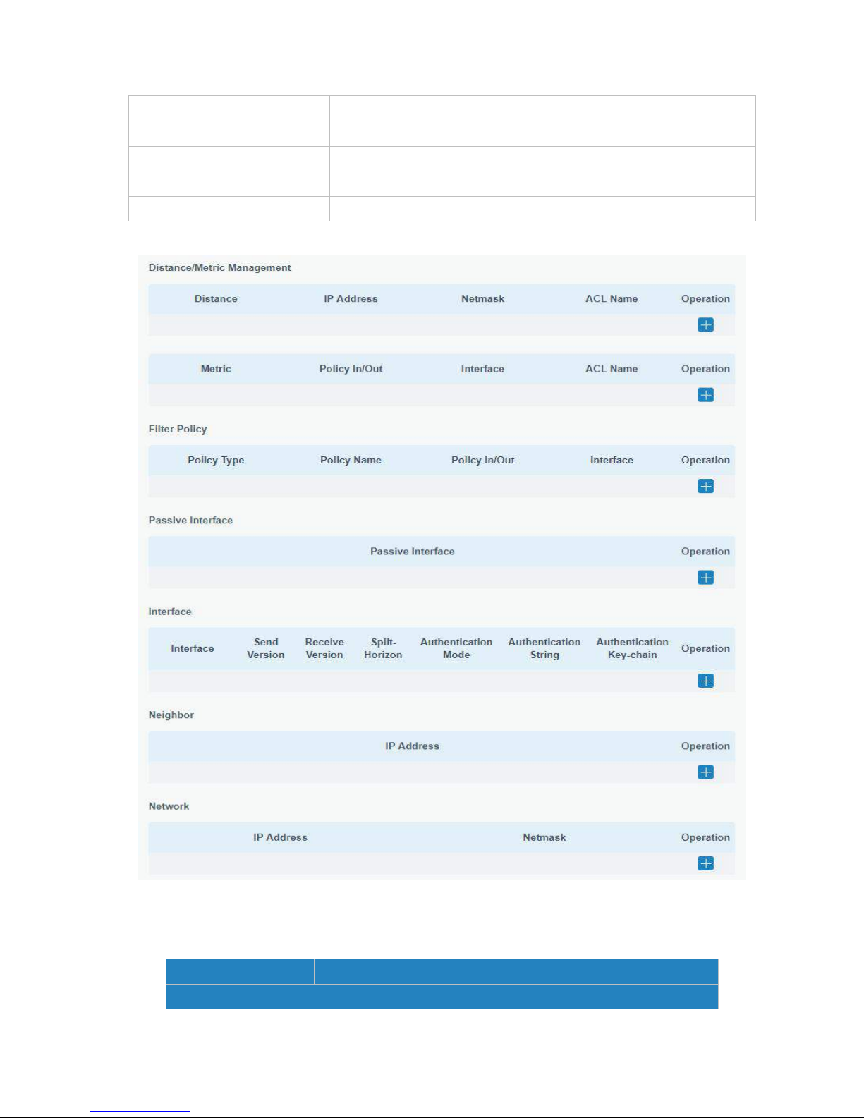
UR52 & UR55 User Guide
60
Metric
Set metric after "Redistribute Connected" is enabled. Range: 0-16.
Redistribute Static
Check to enable.
Metric
Set metric after "Redistribute Static" is enabled. Range: 0-16.
Redistribute OSPF
Check to enable.
Metric
Set metric after "Redistribute OSPF" is enabled. Range: 0-16.
Table 4-2-7-2 RIP Parameters
Figure 4-2-7-3
Item
Description
Distance/Metric Management
Page 61
UR52 & UR55 User Guide
61
Distance
Set the administrative distance that a RIP route learns. Range:
1-255.
IP Address
Set the IP address of RIP route.
Netmask
Set the netmask of RIP route.
ACL Name
Set ACL name of RIP route.
Metric
The metric of received route or sent route from the interface.
Range: 0-16.
Policy in/out
Select from "in" and "out".
Interface
Select interface of the route.
ACL Name
Access control list name of the route strategy.
Filter Policy
Policy Type
Select from "access-list" and "prefix-list".
Policy Name
User-defined prefix-list name.
Policy in/out
Select from "in" and "out".
Interface
Select interface from "cellular0", "FE1" and "FE0".
Passive Interface
Passive Interface
Select interface from "cellular0" and "FE1", "FE0".
Interface
Interface
Select interface from "cellular0", "FE1" and "FE0".
Send Version
Select from "default", "v1" and "v2".
Receive Version
Select from "default", "v1" and "v2".
Split-Horizon
Select from "enable" and "disable".
Authentication Mode
Select from "text" and "md5".
Authentication String
The authentication key for package interaction in RIPV2.
Authentication
Key-chain
The authentication key-chain for package interaction in RIPV2.
Neighbor
IP Address
Set RIP neighbor's IP address manually.
Network
IP Address
The IP address of interface for RIP publishing.
Netmask
The netmask of interface for RIP publishing.
Table 4-2-7-3
Related Configuration Example
Dynamic Routing Application Example
Page 62
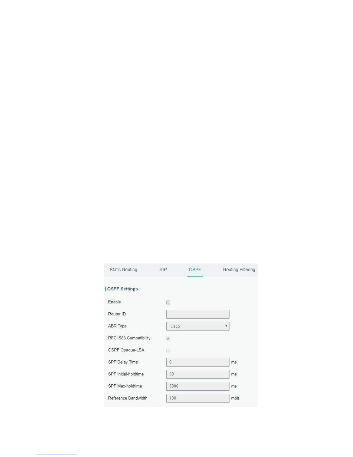
UR52 & UR55 User Guide
62
4.2.7.3 OSPF
OSPF, short for Open Shortest Path First, is a link status based on interior gateway protocol developed by
IETF.
If a router wants to run the OSPF protocol, there should be a Router ID that can be manually configured. If
no Router ID configured, the system will automatically select an IP address of interface as the Router ID.
The selection order is as follows:
- If a Loopback interface address is configured, then the last configured IP address of Loopback
interface will be used as the Router ID;
- If no Loopback interface address is configured, the system will choose the interface with the biggest IP
address as the Router ID.
Five types of packets of OSPF:
- Hello packet
- DD packet (Database Description Packet)
- LSR packet (Link-State Request Packet)
- LSU packet (Link-State Update Packet)
- LSAck packet (Link-Sate Acknowledgment Packet)
Neighbor and Neighboring
After OSPF router starts up, it will send out Hello Packets through the OSPF interface. Upon receipt of
Hello packet, OSPF router will check the parameters defined in the packet. If it’s consistent, a neighbor
relationship will be formed. Not all matched sides in neighbor relationship can form the adjacency
relationship. It is determined by the network type. Only when both sides successfully exchange DD
packets and LSDB synchronization is achieved, the adjacency in the true sense can be formed. LSA
describes the network topology around a router, LSDB describes entire network topology.
Figure 4-2-7-4
Page 63
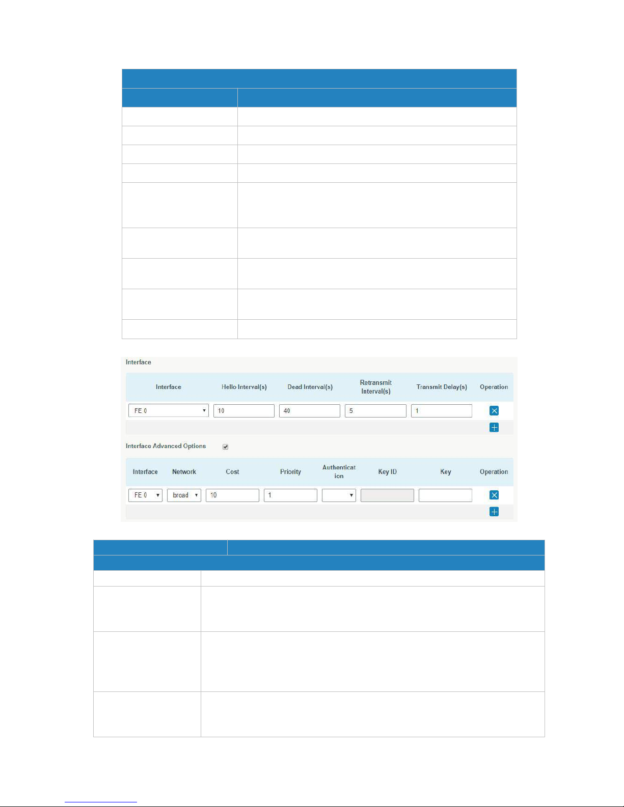
UR52 & UR55 User Guide
63
OSPF
Item
Description
Enable
Enable or disable OSPF.
Router ID
Router ID (IP address) of the originating LSA.
ABR Type
Select from cisco, ibm, standard and shortcut.
RFC1583 Compatibility
Enable/Disable.
OSPF Opaque-LSA
Enable/Disable
LSA: a basic communication means of the OSPF routing
protocol for the Internet Protocol (IP).
SPF Delay Time
Set the delay time for OSPF SPF calculations.
Range: 0-6000000, in milliseconds.
SPF Initial-holdtime
Set the initialization time of OSPF SPF.
Range: 0-6000000, in milliseconds.
SPF Max-holdtime
Set the maximum time of OSPF SPF.
Range: 0-6000000, in milliseconds.
Reference Bandwidth
Range: 1-4294967, in Mbit.
Table 4-2-7-4 OSPF Parameters
Figure 4-2-7-5
Item
Description
Interface
Interface
Select interface from "cellular0" and "FE0".
Hello Interval (s)
Send interval of Hello packet. If the Hello time between two adjacent routers
is different, the neighbour relationship cannot be established. Range:
1-65535.
Dead Interval (s)
Dead Time. If no Hello packet is received from the neighbours within the
dead time, then the neighbour is considered failed. If dead times of two
adjacent routers are different, the neighbour relationship cannot be
established.
Retransmit Interval (s)
When the router notifies an LSA to its neighbour, it is required to make
acknowledgement. If no acknowledgement packet is received within the
retransmission interval, this LSA will be retransmitted to the neighbour.
Page 64
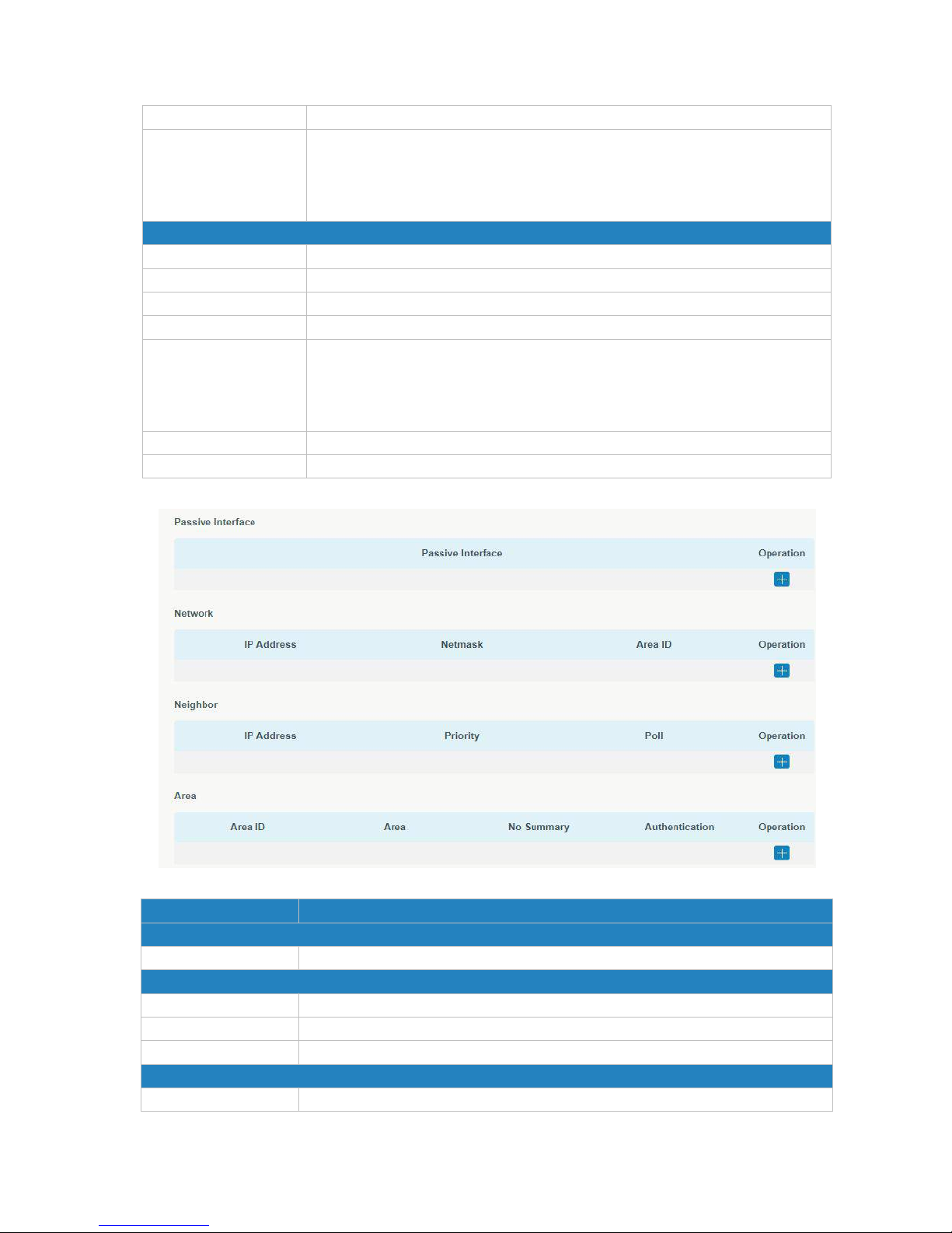
UR52 & UR55 User Guide
64
Range: 3-65535.
Transmit Delay (s)
It will take time to transmit OSPF packets on the link. So a certain delay time
should be increased before transmission the aging time of LSA. This
configuration needs to be further considered on the low-speed link.
Range: 1-65535
Interface Advanced Options
Interface
Select interface.
Network
Select OSPF network type.
Cost
Set the cost of running OSPF on an interface. Range: 1-65535.
Priority
Set the OSPF priority of interface. Range: 0-255.
Authentication
Set the authentication mode that will be used by the OSPF area.
Simple: a simple authentication password should be configured and
confirmed again.
MD5: MD5 key & password should be configured and confirmed again.
Key ID
It only takes effect when MD5 is selected. RanFE 1-255.
Key
The authentication key for OSPF packet interaction.
Table 4-2-7-5 OSPF Parameters
Figure 4-2-7-6
Item
Description
Passive Interface
Passive Interface
Select interface from "cellular0", "FE0" and "FE1".
Network
IP Address
The IP address of local network.
Netmask
The netmask of local network.
Area ID
The area ID of original LSA's router.
Area
Area ID
Set the ID of the OSPF area (IP address).
Page 65
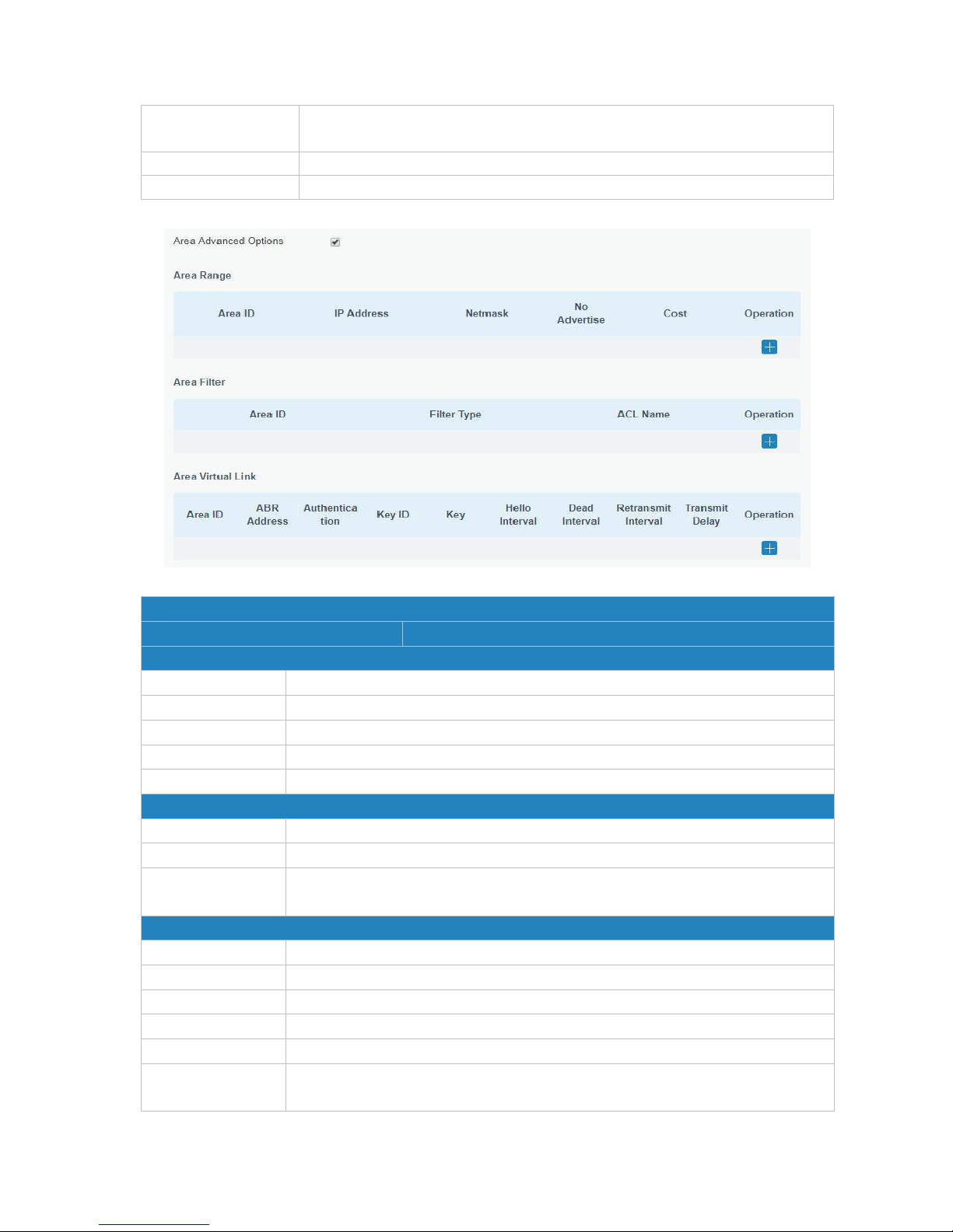
UR52 & UR55 User Guide
65
Area
Select from "Stub" and "NSSA".
The backbone area (area ID 0.0.0.0) cannot be set as "Stub" or "NSSA".
No Summary
Forbid route summarization.
Authentication
Select authentication from "simple" and "md5".
Table 4-2--7-6 OSPF Parameters
Figure 4-2-7-7
Area Advanced Options
Item
Description
Area Range
Area ID
The area ID of the interface when it runs OSPF (IP address).
IP Address
Set the IP address.
Netmask
Set the netmask.
No Advertise
Forbid the route information to be advertised among different areas.
Cost
Range: 0-16777215
Area Filter
Area ID
Select an Area ID for Area Filter.
Filter Type
Select from "import", "export", "filter-in", and "filter-out".
ACL Name
Enter an ACL name which is set on "Routing > Routing Filtering" webpage.
Area Virtual Link
Area ID
Set the ID number of OSPF area.
ABR Address
ABR is the router connected to multiple outer areas.
Authentication
Select from "simple" and "md5".
Key ID
It only takes effect when MD5 is selected. RanFE 1-15.
Key
The authentication key for OSPF packet interaction.
Hello Interval
Set the interval time for sending Hello packets through the interface. Range:
1-65535.
Page 66
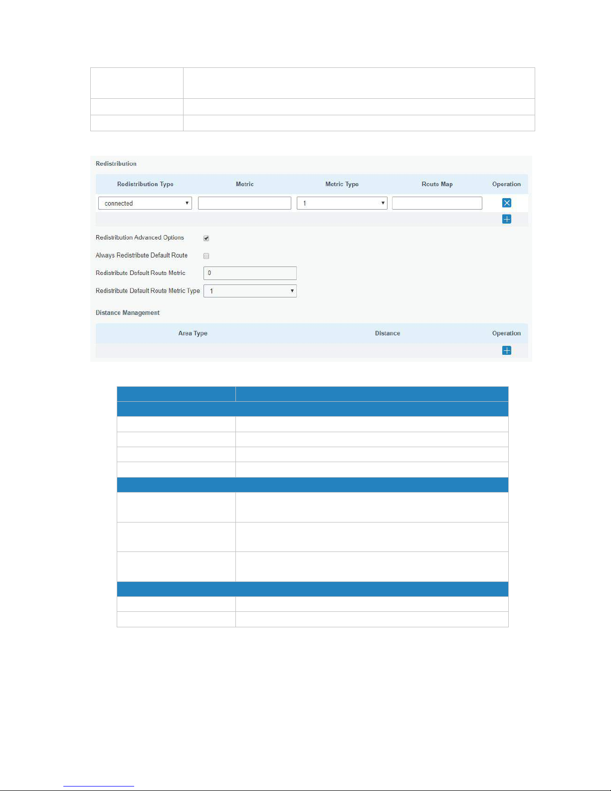
UR52 & UR55 User Guide
66
Dead Interval
The dead interval time for sending Hello packets through the interface. Range:
1-65535.
Retransmit Interval
The retransmission interval time for re-sending LSA. Range: 1-65535.
Transmit Delay
The delay time for LSA transmission. Range: 1-65535.
Table 4-2-7-7 OSPF Parameters
Figure 4-2-7-8
Item
Description
Redistribution
Redistribution Type
Select from "connected", "static" and "rip".
Metric
The metric of redistribution router. Range: 0-16777214.
Metric Type
Select Metric type from "1" and "2".
Route Map
Mainly used to manage route for redistribution.
Redistribution Advanced Options
Always Redistribute
Default Route
Send redistribution default route after starting up.
Redistribute Default
Route Metric
Send redistribution default route metric. Range: 0-16777214.
Redistribute Default
Route Metric Type
Select from "0", "1" and "2".
Distance Management
Area Type
Select from "intra-area", "inter-area" and "external".
Distance
Set the OSPF routing distance for area learning. Range: 1-255.
Table 4-2-7-8 OSPF Parameters
Page 67
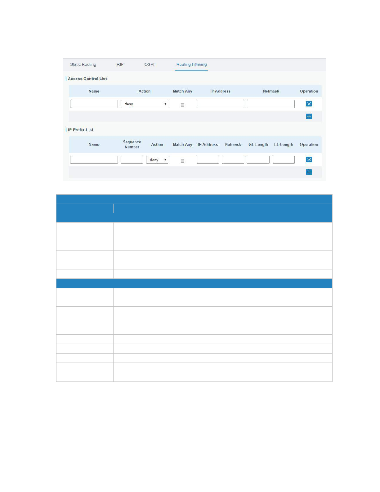
UR52 & UR55 User Guide
67
4.2.7.4 Routing Filtering
Figure 4-2-7-9
Routing Filtering
Item
Description
Access Control List
Name
User-defined name, need to start with a letter. Only letters, digits and underline
(_) are allowed.
Action
Select from "permit" and "deny".
Match Any
No need to set IP address and subnet mask.
IP Address
User-defined.
Netmask
User-defined.
IP Prefix-List
Name
User-defined name, need to start with a letter. Only letters, digits and underline
(_) are allowed.
Sequence Number
A prefix name list can be matched with multiple rules. One rule is matched with
one sequence number. Range: 1-4294967295.
Action
Select from "permit" and "deny".
Match Any
No need to set IP address, subnet mask, FE Length, and LE Length.
IP Address
User-defined.
Netmask
User-defined.
FE Length
Specify the minimum number of mask bits that must be matched. Range: 0-32.
LE Length
Specify the maximum number of mask bits that must be matched. Range: 0-32.
Table 4-2-7-9 Routing Filtering Parameters
4.2.8 VPN
Virtual Private Networks, also called VPNs, are used to securely connect two private networks together so
that devices can connect from one network to the other network via secure channels.
The UR52/UR55 supports DMVPN, IPsec, GRE, L2TP, PPTP, OpenVPN, as well as GRE over IPsec and L2TP
over IPsec.
Page 68
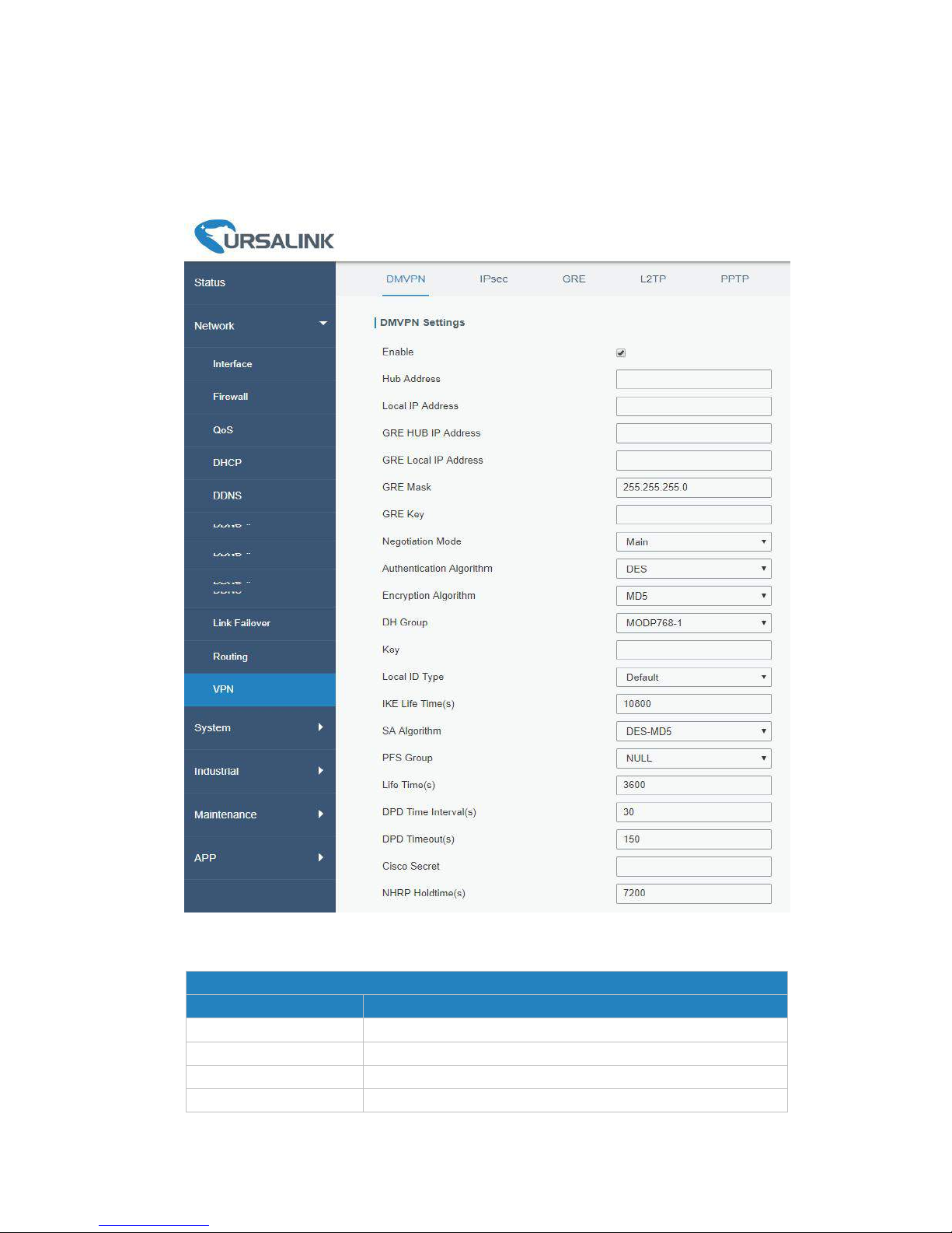
UR52 & UR55 User Guide
68
4.2.8.1 DMVPN
A dynamic multi-point virtual private network (DMVPN), combining mGRE and IPsec, is a secure network
that exchanges data between sites without passing traffic through an organization's headquarter VPN
server or router.
Figure 4-2-8-1
DMVPN
Item
Description
Enable
Enable or disable DMVPN.
Hub Address
The IP address or domain name of DMVPN Hub.
Local IP address
DMVPN local tunnel IP address.
GRE Hub IP Address
GRE Hub tunnel IP address.
Page 69

UR52 & UR55 User Guide
69
GRE Local IP Address
GRE local tunnel IP address.
GRE Netmask
GRE local tunnel netmask.
GRE Key
GRE tunnel key.
Negotiation Mode
Select from "Main" and "Aggressive".
Authentication
Algorithm
Select from "DES", "3DES", "AES128", "AES192" and "AES256".
Encryption Algorithm
Select from "MD5" and "SHA1".
DH Group
Select from "MODP768_1", "MODP1024_2" and
"MODP1536_5".
Key
Enter the preshared key.
Local ID Type
Select from "Default", "ID", "FQDN", and "User FQDN"
IKE Life Time (s)
Set the lifetime in IKE negotiation. Range: 60-86400.
SA Algorithm
Select from "DES_MD5", "DES_SHA1", "3DES_MD5",
"3DES_SHA1", "AES128_MD5", "AES128_SHA1",
"AES192_MD5", "AES192_SHA1", "AES256_MD5" and
"AES256_SHA1".
PFS Group
Select from "NULL", "MODP768_1", "MODP1024_2" and
"MODP1536-5".
Life Time (s)
Set the lifetime of IPsec SA. Range: 60-86400.
DPD Interval Time (s)
Set DPD interval time
DPD Timeout (s)
Set DPD timeout.
Cisco Secret
Cisco Nhrp key.
NHRP Holdtime (s)
The holdtime of NHRP protocol.
Table 4-2-8-1 DMVPN Parameters
4.2.8.2 IPSec
IPsec is especially useful for implementing virtual private networks and for remote user access through
dial-up connection to private networks. A big advantage of IPsec is that security arrangements can be
handled without requiring changes to individual user computers.
IPsec provides three choices of security service: Authentication Header (AH), Encapsulating Security
Payload (ESP), and Internet Key Exchange (IKE). AH essentially allows authentication of the senders’ data.
ESP supports both authentication of the sender and data encryption. IKE is used for cipher code exchange.
All of them can protect one and more data flows between hosts, between host and gateway, and between
gateways.
Page 70
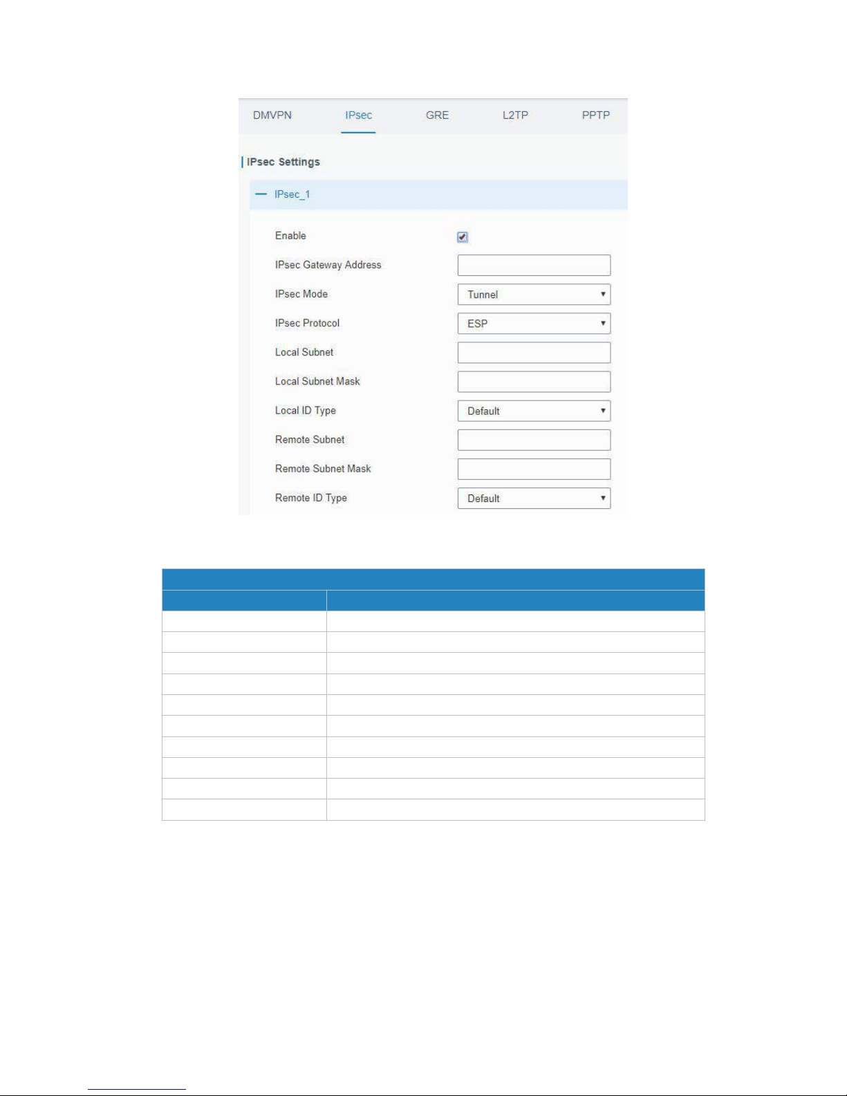
UR52 & UR55 User Guide
70
Figure 4-2-8-2
IPsec
Item
Description
Enable
Enable IPsec tunnel. A maximum of 3 tunnels is allowed.
IPsec Gateway Address
Enter the IP address or domain name of remote IPsec server.
IPsec Mode
Select from "Tunnel" and "Transport".
IPsec Protocol
Select from "ESP" and "AH".
Local Subnet
Enter the local subnet IP address that IPsec protects.
Local Subnet Netmask
Enter the local netmask that IPsec protects.
Local ID Type
Select from "Default", "ID", "FQDN", and "User FQDN".
Remote Subnet
Enter the remote subnet IP address that IPsec protects.
Remote Subnet Mask
Enter the remote netmask that IPsec protects.
Remote ID type
Select from "Default", "ID", "FQDN", and "User FQDN".
Table 4-2-8-2 IPsec Parameters
Page 71
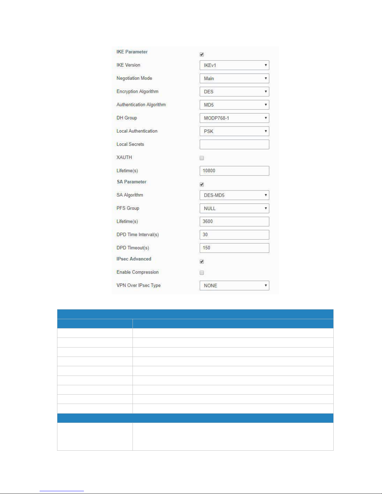
UR52 & UR55 User Guide
71
Figure 4-2-8-3
IKE Parameter
Item
Description
IKE Version
Select from "IKEv1" and "IKEv2".
Negotiation Mode
Select from "Main" and "Aggressive".
Encryption Algorithm
Select from "DES", "3DES", "AES128", "AES192" and "AES256".
Authentication Algorithm
Select from "MD5" and " SHA1"
DH Group
Select from "MODP768_1", "MODP1024_2" and "MODP1536_5".
Local Authentication
Select from "PSK" and "CA".
Local Secrets
Enter the pre-shared key.
XAUTH
Enter XAUTH username and password after XAUTH is enabled.
Lifetime (s)
Set the lifetime in IKE negotiation. Range: 60-86400.
SA Parameter
SA Algorithm
Select from "DES_MD5", "DES_SHA1", "3DES_MD5", "3DES_SHA1",
"AES128_MD5", "AES128_SHA1", "AES192_MD5", "AES192_SHA1",
"AES256_MD5" and "AES256_SHA1".
Page 72
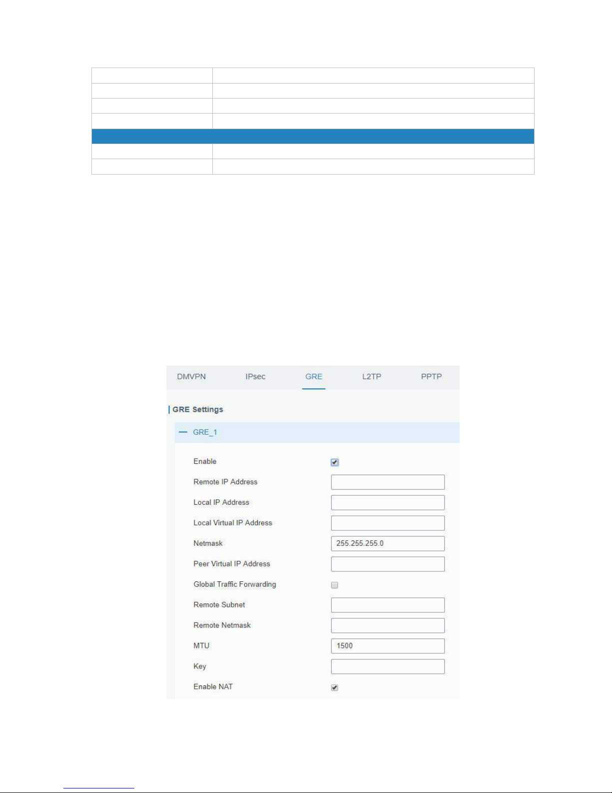
UR52 & UR55 User Guide
72
PFS Group
Select from "NULL", "MODP768_1" , "MODP1024_2" and "MODP1536_5".
Lifetime (s)
Set the lifetime of IPsec SA. Range: 60-86400.
DPD Interval Time(s)
Set DPD interval time to detect if the remote side fails.
DPD Timeout(s)
Set DPD timeout. Range: 10-3600.
IPsec Advanced
Enable Compression
The head of IP packet will be compressed after it's enabled.
VPN Over IPsec Type
Select from "NONE", "GRE" and "L2TP" to enable VPN over IPsec function.
Table 4-2-8-3 IPsec Parameters
4.2.8.3 GRE
Generic Routing Encapsulation (GRE) is a protocol that encapsulates packets in order to route other
protocols over IP networks. It’s a tunneling technology that provides a channel through which
encapsulated data message could be transmitted and encapsulation and decapsulation could be realized
at both ends.
In the following circumstances the GRE tunnel transmission can be applied:
- GRE tunnel could transmit multicast data packets as if it were a true network interface. Single use of
IPSec cannot achieve the encryption of multicast.
- A certain protocol adopted cannot be routed.
- A network of different IP addresses shall be required to connect other two similar networks.
Figure 4-2-8-4
Page 73
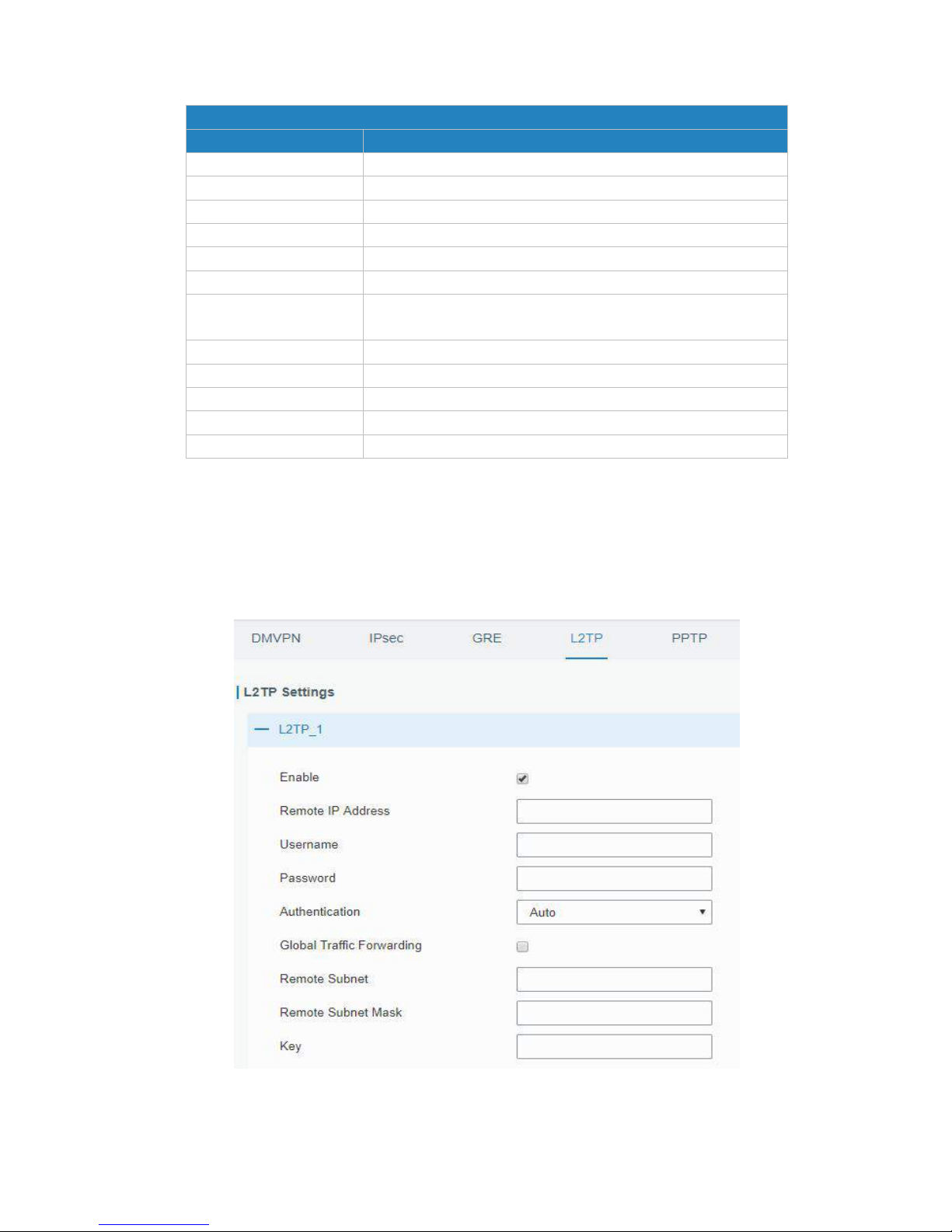
UR52 & UR55 User Guide
73
GRE
Item
Description
Enable
Check to enable GRE function.
Remote IP Address
Enter the real remote IP address of GRE tunnel.
Local IP Address
Set the local IP address.
Local Virtual IP Address
Set the local tunnel IP address of GRE tunnel.
Netmask
Set the local netmask.
Peer Virtual IP Address
Enter remote tunnel IP address of GRE tunnel.
Global Traffic
Forwarding
All the data traffic will be sent out via GRE tunnel when this
function is enabled.
Remote Subnet
Enter the remote subnet IP address of GRE tunnel.
Remote Netmask
Enter the remote netmask of GRE tunnel.
MTU
Enter the maximum transmission unit. Range: 64-1500.
Key
Set GRE tunnel key.
Enable NAT
Enable NAT traversal function.
Table 4-2-8-4 GRE Parameters
4.2.8.4 L2TP
Layer Two Tunneling Protocol (L2TP) is an extension of the Point-to-Point Tunneling Protocol (PPTP) used
by an Internet service provider (ISP) to enable the operation of a virtual private network (VPN) over the
Internet.
Figure 4-2-8-5
Page 74
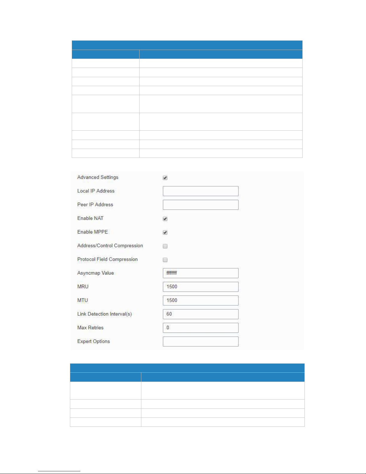
UR52 & UR55 User Guide
74
L2TP
Item
Description
Enable
Check to enable L2TP function.
Remote IP Address
Enter the public IP address or domain name of L2TP server.
Username
Enter the username that L2TP server provides.
Password
Enter the password that L2TP server provides.
Authentication
Select from "Auto", "PAP", "CHAP", "MS-CHAPv1" and
"MS-CHAPv2".
Global Traffic
Forwarding
All of the data traffic will be sent out via L2TP tunnel after this
function is enabled.
Remote Subnet
Enter the remote IP address that L2TP protects.
Remote Subnet Mask
Enter the remote netmask that L2TP protects.
Key
Enter the password of L2TP tunnel.
Table 4-2-8-5 L2TP Parameters
Figure 4-2-8-6
Advanced Settings
Item
Description
Local IP Address
Set tunnel IP address of L2TP client. Client will obtain tunnel IP
address automatically from the server when it's null.
Peer IP Address
Enter tunnel IP address of L2TP server.
Enable NAT
Enable NAT traversal function.
Enable MPPE
Enable MPPE encryption.
Page 75
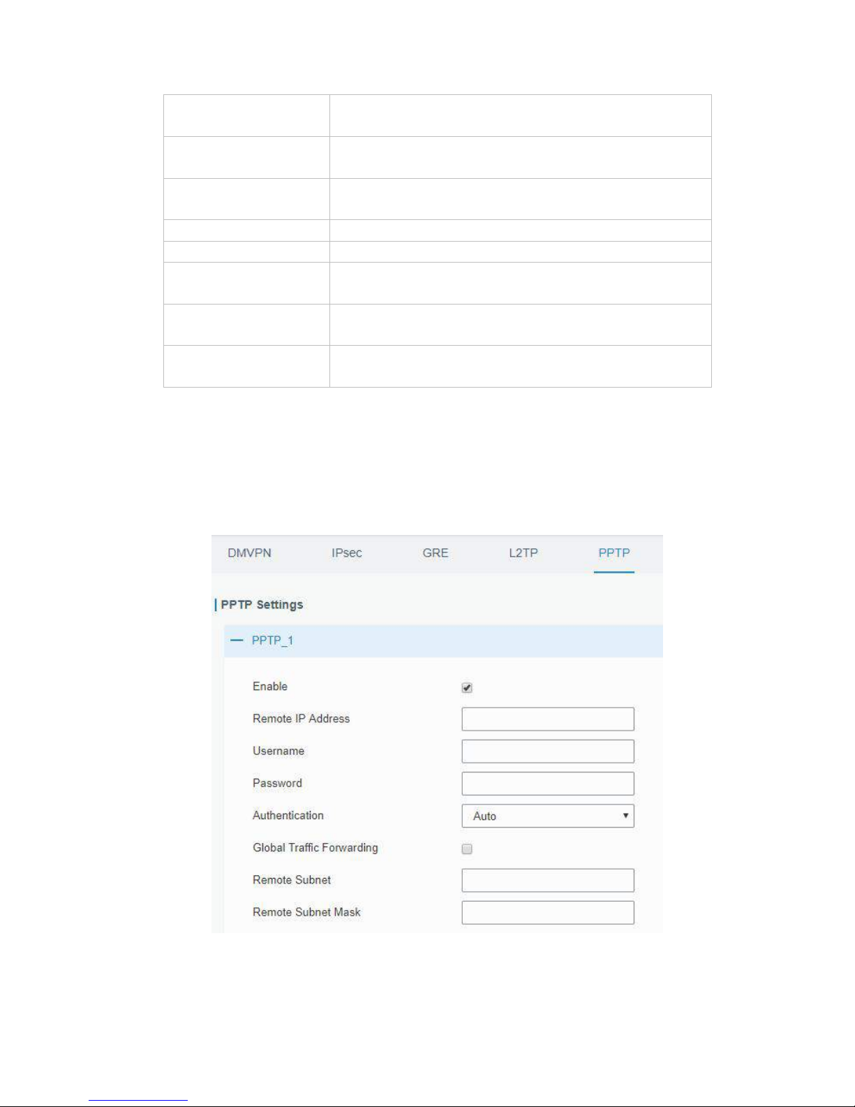
UR52 & UR55 User Guide
75
Address/Control
Compression
For PPP initialization. User can keep the default option.
Protocol Field
Compression
For PPP initialization. User can keep the default option.
Asyncmap Value
One of the PPP protocol initialization strings. User can keep
the default value. Range: 0-ffffffff.
MRU
Set the maximum receive unit. Range: 64-1500.
MTU
Set the maximum transmission unit. Range: 64-1500
Link Detection Interval (s)
Set the link detection interval time to ensure tunnel
connection. Range: 0-600.
Max Retries
Set the maximum times of retry to detect the L2TP connection
failure. Range: 0-10.
Expert Options
User can enter some other PPP initialization strings in this
field and separate the strings with blank space.
Table 4-2-8-6 L2TP Parameters
4.2.8.5 PPTP
Point-to-Point Tunneling Protocol (PPTP) is a protocol that allows corporations to extend their own
corporate network through private "tunnels" over the public Internet. Effectively, a corporation uses a
wide-area network as a single large local area network.
Figure 4-2-8-7
Page 76
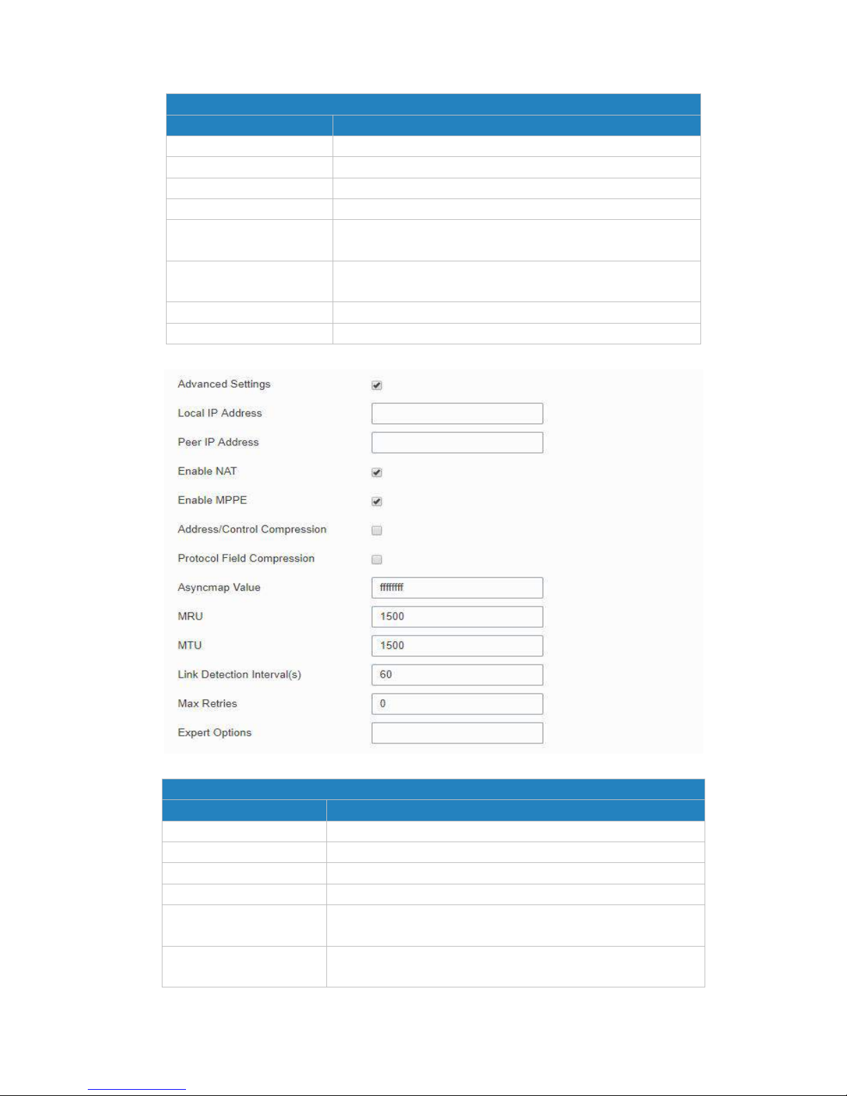
UR52 & UR55 User Guide
76
PPTP
Item
Description
Enable
Enable PPTP client. A maximum of 3 tunnels is allowed.
Remote IP Address
Enter the public IP address or domain name of PPTP server.
Username
Enter the username that PPTP server provides.
Password
Enter the password that PPTP server provides.
Authentication
Select from "Auto", "PAP", "CHAP", "MS-CHAPv1", and
"MS-CHAPv2".
Global Traffic Forwarding
All of the data traffic will be sent out via PPTP tunnel once
enable this function.
Remote Subnet
Set the peer subnet of PPTP.
Remote Subnet Mask
Set the netmask of peer PPTP server.
Table 4-2-8-7 PPTP Parameters
Figure 4-2-8-8
PPTP Advanced Settings
Item
Description
Local IP Address
Set IP address of PPTP client.
Peer IP Address
Enter tunnel IP address of PPTP server.
Enable NAT
Enable the NAT faction of PPTP.
Enable MPPE
Enable MPPE encryption.
Address/Control
Compression
For PPP initialization. User can keep the default option.
Protocol Field
Compression
For PPP initialization. User can keep the default option.
Page 77

UR52 & UR55 User Guide
77
Asyncmap Value
One of the PPP protocol initialization strings. User can keep
the default value. Range: 0-ffffffff.
MRU
Enter the maximum receive unit. Range: 0-1500.
MTU
Enter the maximum transmission unit. Range: 0-1500.
Link Detection Interval (s)
Set the link detection interval time to ensure tunnel
connection. Range: 0-600.
Max Retries
Set the maximum times of retrying to detect the PPTP
connection failure. Range: 0-10.
Expert Options
User can enter some other PPP initialization strings in this
field and separate the strings with blank space.
Table 4-2-8-8 PPTP Parameters
Related Configuration Example
PPTP Application Example
4.2.8.6 OpenVPN Client
OpenVPN is an open source virtual private network (VPN) product that offers a simplified security
framework, modular network design, and cross-platform portability.
Advantages of OpenVPN include:
- Security provisions that function against both active and passive attacks.
- Compatibility with all major operating systems.
- High speed (1.4 megabytes per second typically).
- Ability to configure multiple servers to handle numerous connections simultaneously.
- All encryption and authentication features of the OpenSSL library.
- Advanced bandwidth management.
- A variety of tunneling options.
- Compatibility with smart cards that support the Windows Crypt application program interface (API).
Page 78
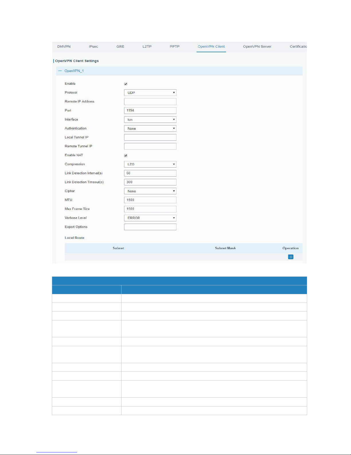
UR52 & UR55 User Guide
78
Figure 4-2-8-9
OpenVPN Client
Item
Description
Enable
Enable OpenVPN client. A maximum of 3 tunnels is allowed.
Protocol
Select from "UDP" and "TCP".
Remote IP Address
Enter remote OpenVPN server's IP address or domain name.
Port
Enter the listening port number of remote OpenVPN server. Range:
1-65535.
Interface
Select from "tun" and "tap".
Authentication
Select from "None", "Pre-shared", "Username/Password", "X.509 cert",
and "X.509 cert+user".
Local Tunnel IP
Set local tunnel address.
Remote Tunnel IP
Enter remote tunnel address.
Global Traffic Forwarding
All the data traffic will be sent out via OpenVPN tunnel when this function
is enabled.
Enable TLS Authentication
Check to enable TLS authentication.
Username
Enter username provided by OpenVPN server.
Page 79
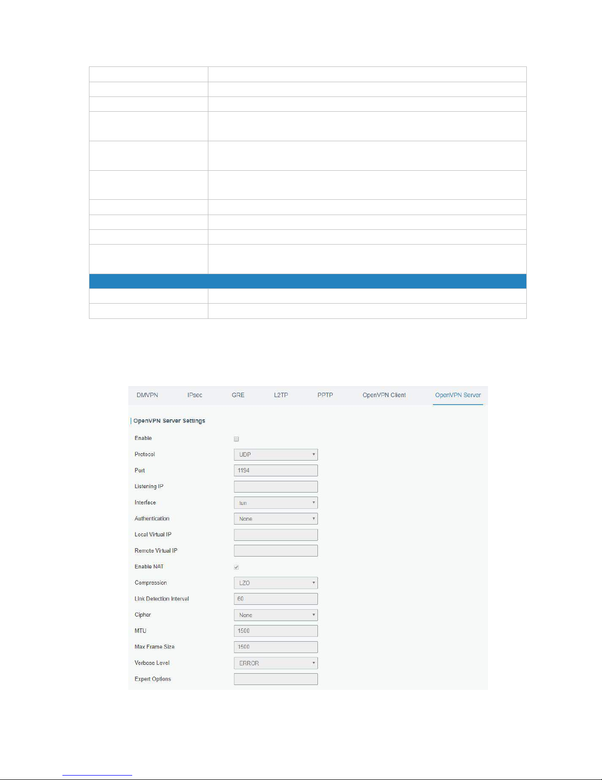
UR52 & UR55 User Guide
79
Password
Enter password provided by OpenVPN server.
Enable NAT
Enable NAT traversal function.
Compression
Select LZO to compress data.
Link Detection Interval (s)
Set link detection interval time to ensure tunnel connection. Range:
10-1800.
Link Detection Timeout (s)
Set link detection timeout. OpenVPN will be reestablished after timeout.
Range: 60-3600.
Cipher
Select from "NONE", "BF-CBC", "DE-CBC", "DES-EDE3-CBC",
"AES-128-CBC", "AES-192-CBC" and "AES-256-CBC".
MTU
Enter the maximum transmission unit. Range: 128-1500.
Max Frame Size
Set the maximum frame size. Range: 128-1500.
Verbose Level
Select from "ERROR", "WARING", "NOTICE" and "DEBUG".
Expert Options
User can enter some other PPP initialization strings in this field and
separate the strings with blank space.
Local Route
Subnet
Set the local route's IP address.
Subnet Mask
Set the local route's netmask.
Table 4-2-8-9 OpenVPN Client Parameters
4.2.8.7 OpenVPN Server
The UR52/UR55 supports OpenVPN server to create secure point-to-point or site-to-site connections in
routed or bridged configurations and remote access facilities.
Figure 4-2-8-10
Page 80
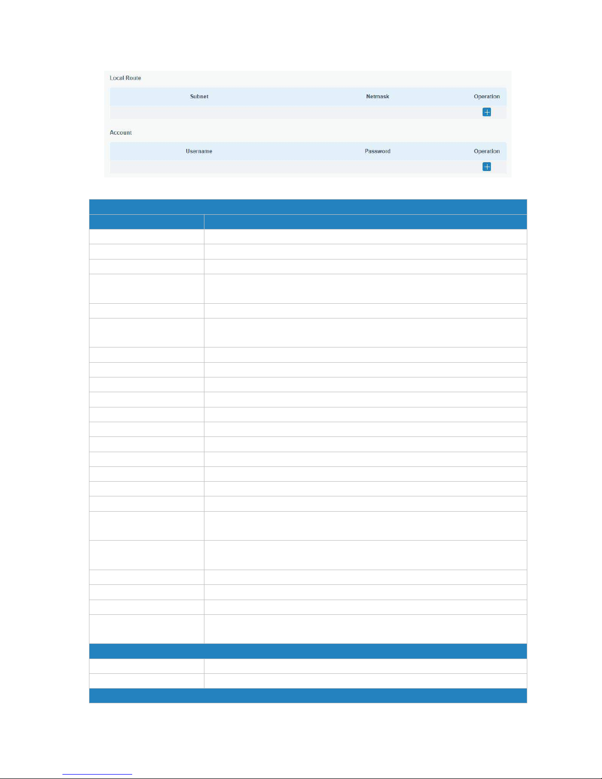
UR52 & UR55 User Guide
80
Figure 4-2-8-11
OpenVPN Server
Item
Description
Enable
Enable/disable OpenVPN server.
Protocol
Select from TCP and UDP.
Port
Fill in listening port number. Range: 1-65535.
Listening IP
Enter WAN IP address or LAN IP address. Leaving it blank refers to all active
WAN IP and LAN IP address.
Interface
Select from " tun" and "tap".
Authentication
Select from "None", "Pre-shared", "Username/Password", "X.509 cert" and
"X. 509 cert +user".
Local Virtual IP
The local tunnel address of OpenVPN's tunnel.
Remote Virtual IP
The remote tunnel address of OpenVPN's tunnel.
Client Subnet
Local subnet IP address of OpenVPN client.
Client Netmask
Local netmask of OpenVPN client.
Renegotiation Interval(s)
Set interval for renegotiation. Range: 0-86400.
Max Clients
Maximum OpenVPN client number. Range: 1-128.
Enable CRL
Enable CRL
Enable Client to Client
Allow access between different OpenVPN clients.
Enable Dup Client
Allow multiple users to use the same certification.
Enable NAT
Check to enable the NAT traversal function.
Compression
Select "LZO" to compress data.
Link Detection Interval
Set link detection interval time to ensure tunnel connection. Range:
10-1800.
Cipher
Select from "NONE", "BF-CBC", "DES-CBC", "DES-EDE3-CBC",
"AES-128-CBC", "AES-192-CBC" and "AES-256-CBC".
MTU
Enter the maximum transmission unit. Range: 64-1500.
Max Frame Size
Set the maximum frame size. Range: 64-1500.
Verbose Level
Select from "ERROR", "WARING", "NOTICE" and "DEBUG".
Expert Options
User can enter some other PPP initialization strings in this field and
separate the strings with blank space.
Local Route
Subnet
The real local IP address of OpenVPN client.
Netmask
The real local netmask of OpenVPN client.
Account
Page 81
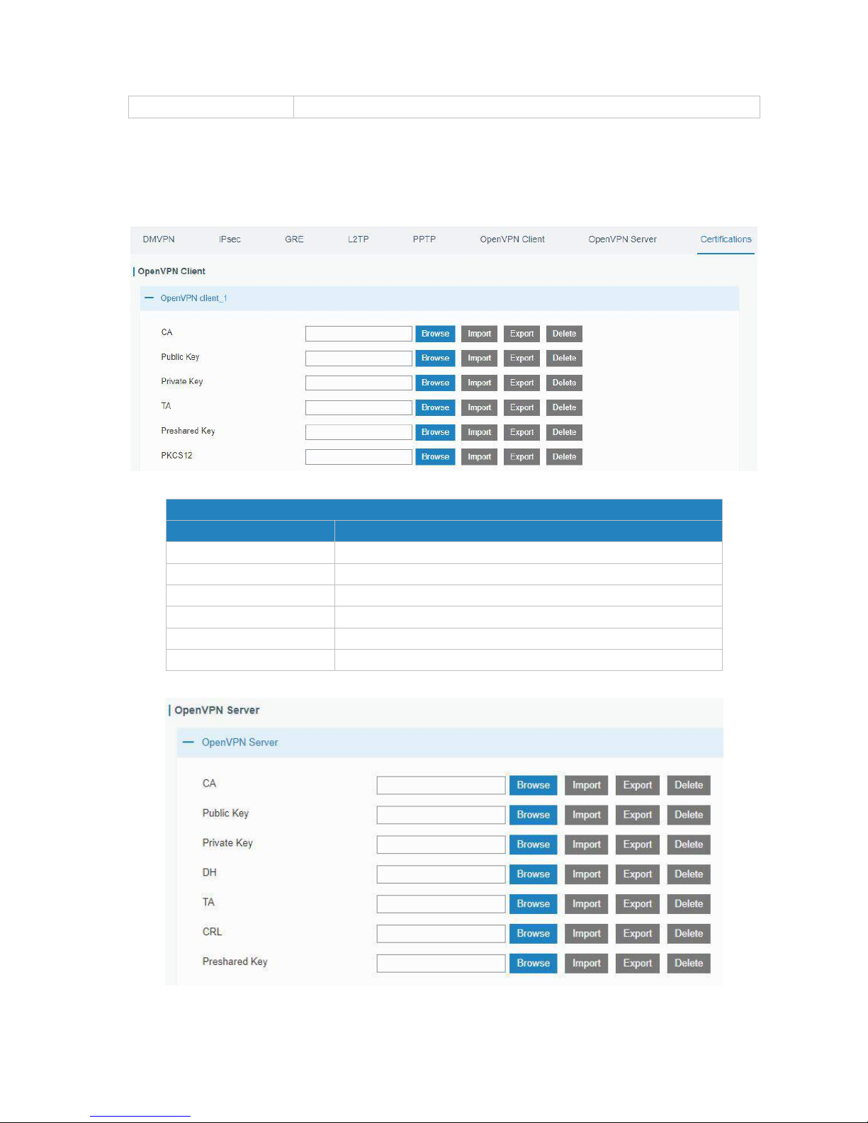
UR52 & UR55 User Guide
81
Username & Password
Set username and password for OpenVPN client.
Table 4-2-8-10 OpenVPN Server Parameters
4.2.8.8 Certifications
User can import/export certificate and key files for OpenVPN and IPsec on this page.
Figure 4-2-8-12
OpenVPN Client
Item
Description
CA
Import/Export CA certificate file.
Public Key
Import/Export public key file.
Private Key
Import/Export private key file.
TA
Import/Export TA key file.
Preshared Key
Import/Export static key file.
PKCS12
Import/Export PKCS12 certificate file.
Table 4-2-8-11 OpenVPN Client Certification Parameters
Figure 4-2-8-13
Page 82
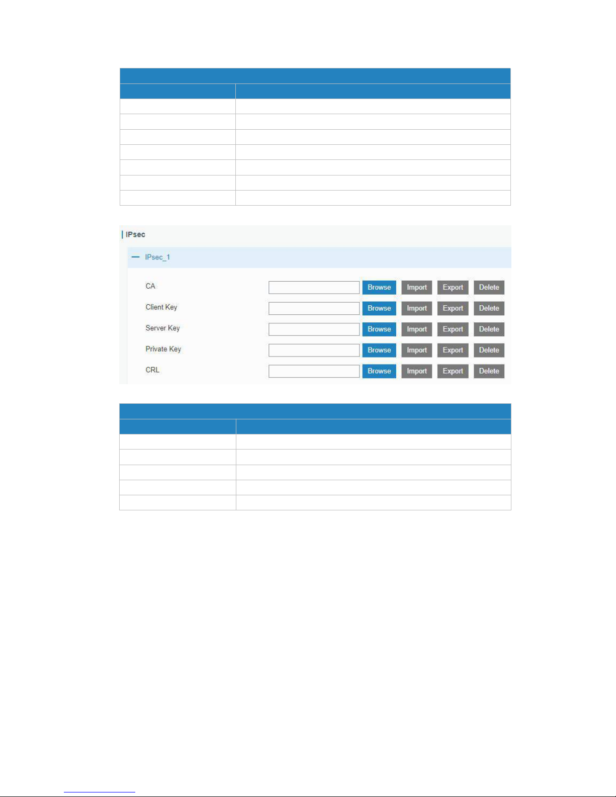
UR52 & UR55 User Guide
82
OpenVPN Server
Item
Description
CA
Import/Export CA certificate file.
Public Key
Import/Export public key file.
Private Key
Import/Export private key file.
DH
Import/Export DH key file.
TA
Import/Export TA key file.
CRL
Import/Export CRL.
Preshared Key
Import/Export static key file.
Table 4-2-8-12 OpenVPN Server Parameters
Figure 4-2-8-14
IPsec
Item
Description
CA
Import/Export CA certificate.
Client Key
Import/Export client key.
Server Key
Import/Export server key.
Private Key
Import/Export private key.
CRL
Import/Export certificate recovery list.
Table 4-2-8-13 IPsec Parameters
4.3 System
This section describes how to configure general settings, such as administration account, access service,
system time, common user management, SNMP, AAA, event alarms, etc.
4.3.1 General Settings
4.3.1.1 General
General settings include system info, access service and HTTPS certificates.
Page 83
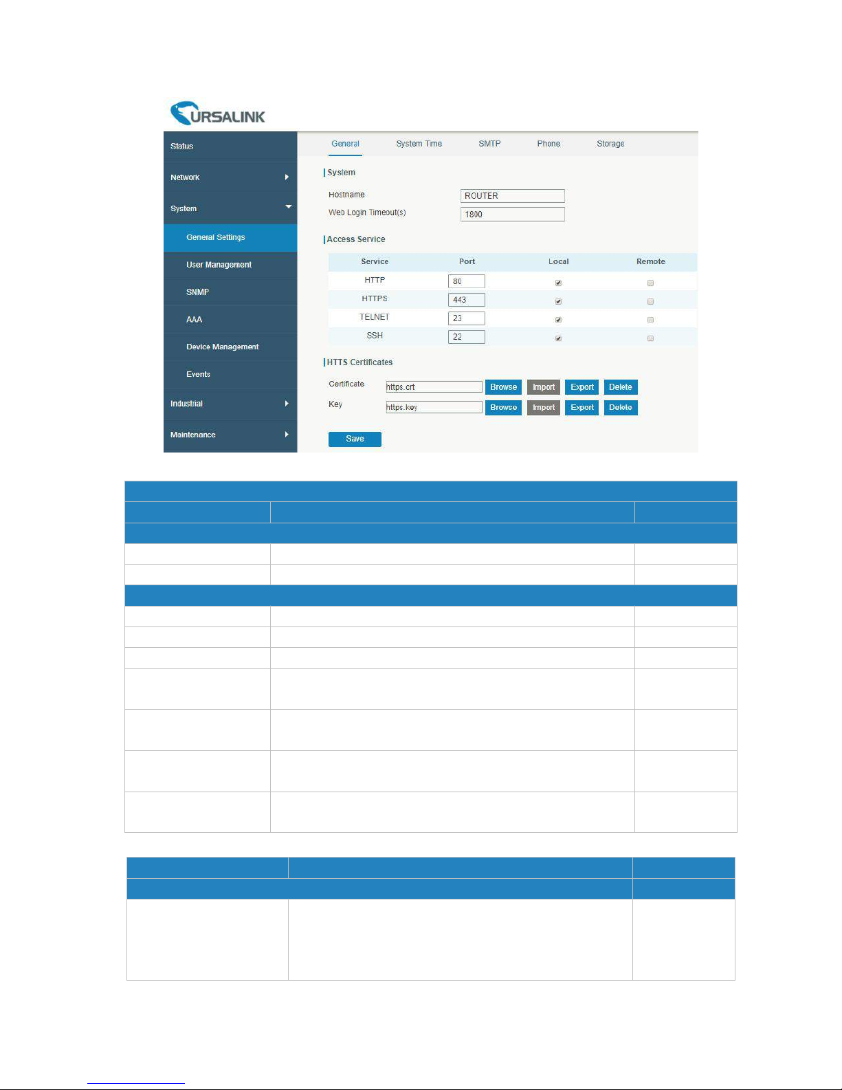
UR52 & UR55 User Guide
83
Figure 4-3-1-1
General
Item
Description
Default
System
Hostname
User-defined router name, needs to start with a letter.
ROUTER
Web Login Timeout (s)
You need to log in again if it times out. Range: 100-3600.
1800
Access Service
Local
Access the router locally.
Enable
Port
Set port number of the services. Range: 1-65535.
--
Remote
Access the router remotely.
Disable
HTTP
Users can log in the device locally via HTTP to access and
control it through Web after the option is checked.
80
HTTPS
Users can log in the device locally and remotely via HTTPS to
access and control it through Web after option is checked.
443
TELNET
Users can log in the device locally and remotely via Telnet
after the option is checked.
23
SSH
Users can log in the device locally and remotely via SSH after
the option is checked.
22
Table 4-3-1-1 General Setting Parameters
Item
Description
Default
HTTPS Certificates
Certificate
Click "Browse" button, choose certificate file on the PC,
and then click "Import" button to upload the file into
router. Click "Export" button will export the file to the
PC. Click "Delete" button will delete the file.
--
Page 84
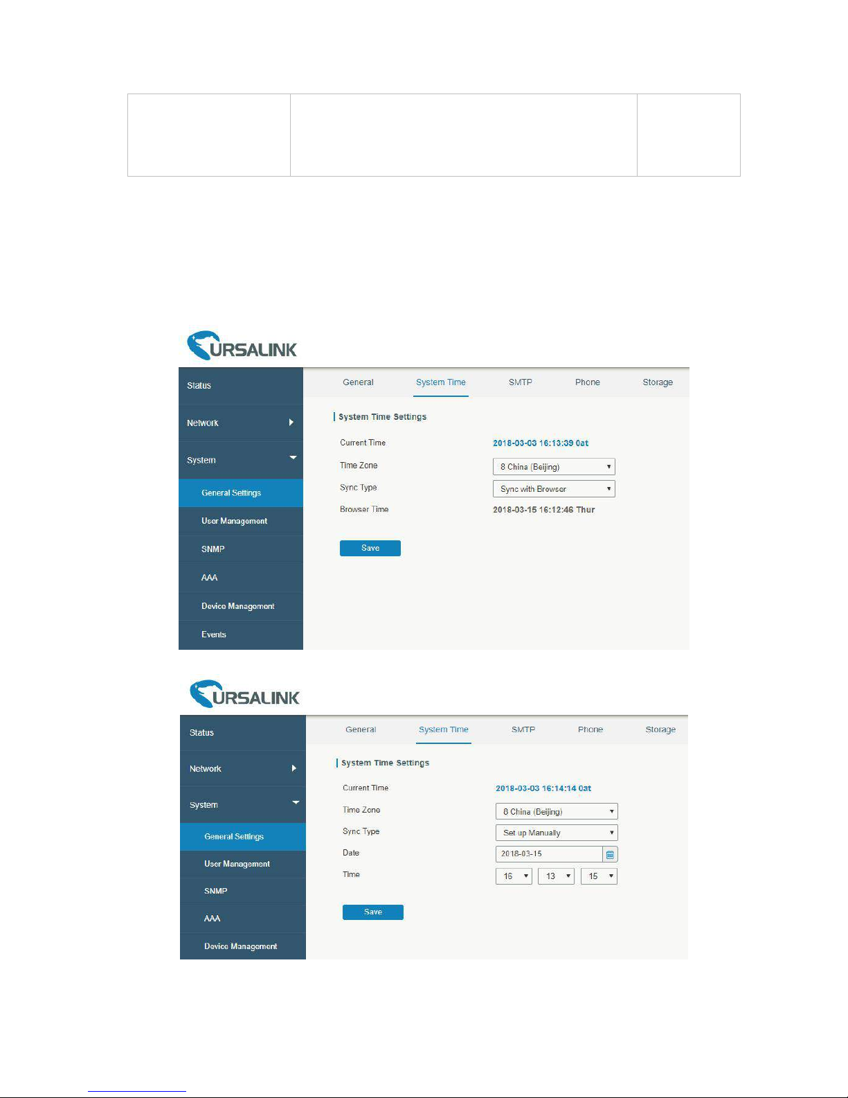
UR52 & UR55 User Guide
84
Key
Click "Browse" button, choose key file on the PC, and
then click "Import" button to upload the file into router.
Click "Export" button will export file to the PC.
Click "Delete" button will delete the file.
--
Table 4-3-1-2 General Setting Parameters
4.3.1.3 System Time
This section explains how to set the system time including time zone and time synchronization type.
Note: to ensure that the router runs with the correct time, it’s recommended that you set the system
time when configuring the router.
Figure 4-3-1-3
Figure 4-3-1-4
Page 85
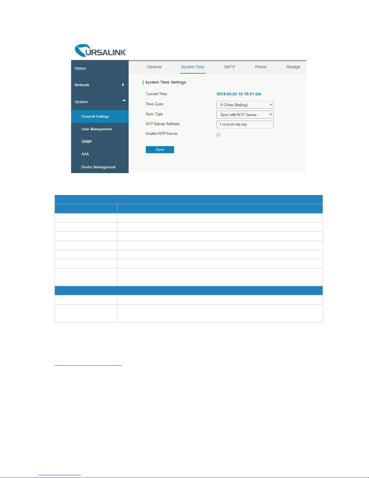
UR52 & UR55 User Guide
85
Figure 4-3-1-5
System Time
Item
Description
Current Time
Show the current system time.
Time Zone
Click the drop down list to select the time zone you are in.
Sync Type
Click the drop down list to select the time synchronization type.
Sync with Browser
Synchronize time with browser.
Browser Time
Show the current time of browser.
Set up Manually
Manually configure the system time.
Sync with NTP Server
Synchronize time with NTP server so as to achieve time synchronization of all
devices equipped with a clock on network.
Sync with NTP Server
NTP Server Address
Set NTP server address (domain name/IP).
Enable NTP Server
NTP client on the network can achieve time synchronization with router after
"Enable NTP Server" option is checked.
Table 4-3-1-4 System Time Parameters
Related Configuration Example
System Time Management
4.3.1.4 SMTP
SMTP, short for Simple Mail Transfer Protocol, is a TCP/IP protocol used in sending and receiving e-mail.
This section describes how to configure email settings.
Page 86
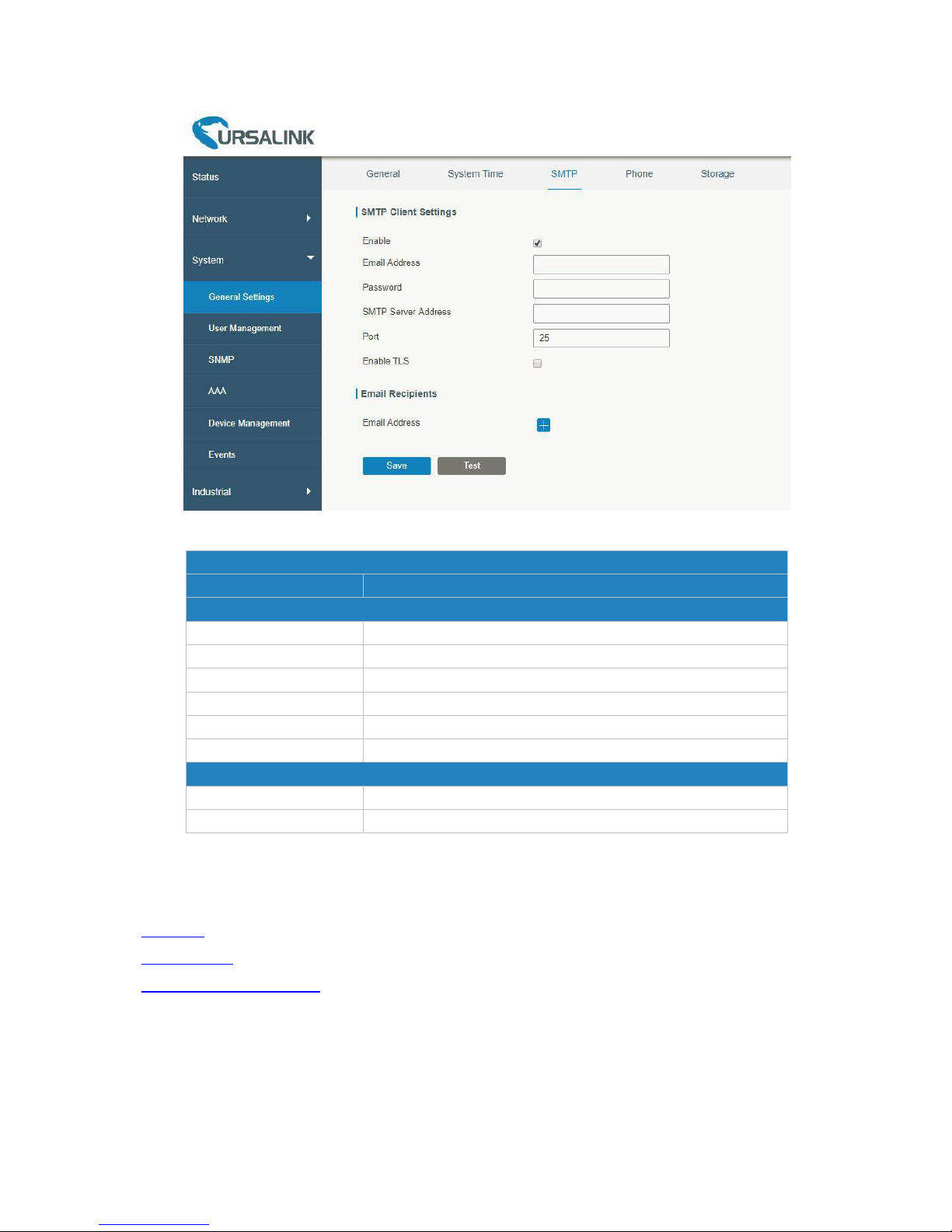
UR52 & UR55 User Guide
86
Figure 4-3-1-6
SMTP
Item
Description
SMTP Client Settings
Enable
Enable or disable SMTP client function.
Email Address
Enter the sender's email account.
Password
Enter the sender's email password.
SMTP Server Address
Enter SMTP server's domain name.
Port
Enter SMTP server port. Range: 1-65535.
Enable TLS
Enable or disable TLS encryption.
Email Recipients
Email Address
Add recipients' email address.
Test
Check if the recipients can get the mail from sender.
Table 4-3-1-5 SMTP Setting
Related Topics
DI Setting
Events Setting
Events Application Example
Page 87
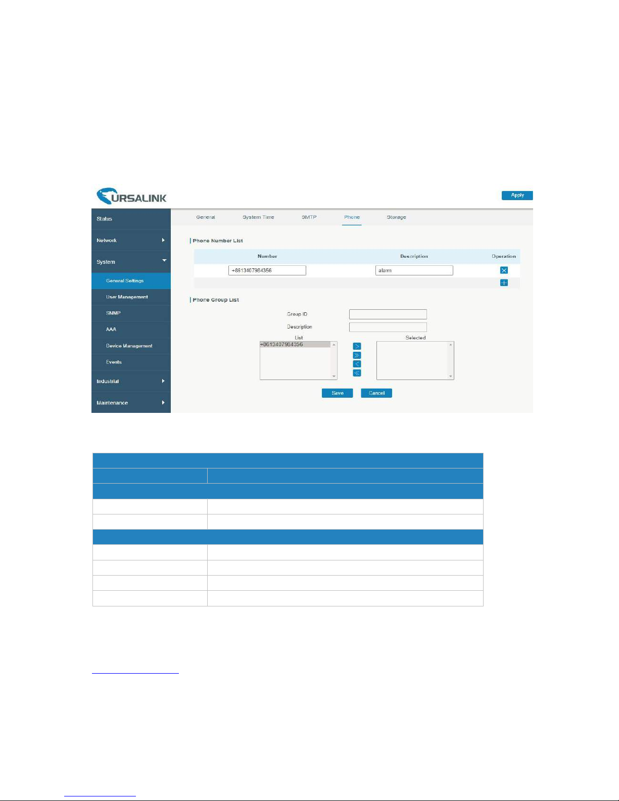
UR52 & UR55 User Guide
87
4.3.1.5 Phone
Phone settings involve in call/SMS trigger and SMS alarm for events.
1. Add phone list.
2. Select phone numbers and add them to the phone group.
3. Go to “Network > Interface > Cellular > Connection Mode > Connect on Demand > Trigger by Call /
Trigger by SMS” or go to “System > Events > Event Settings > SMS” and then select the phone group
ID.
Figure 4-3-1-7
Phone
Item
Description
Phone Number List
Number
Enter the telephone number. Digits, "+" and "-" are allowed.
Description
The description of the telephone number.
Phone Group
Group ID
Set number for phone group. Range: 1-100.
Description
The description of the phone group.
List
Show the phone list.
Selected
Show the selected phone number.
Table 4-3-1-6 Phone Settings
Related Topic
Connect on Demand
Page 88
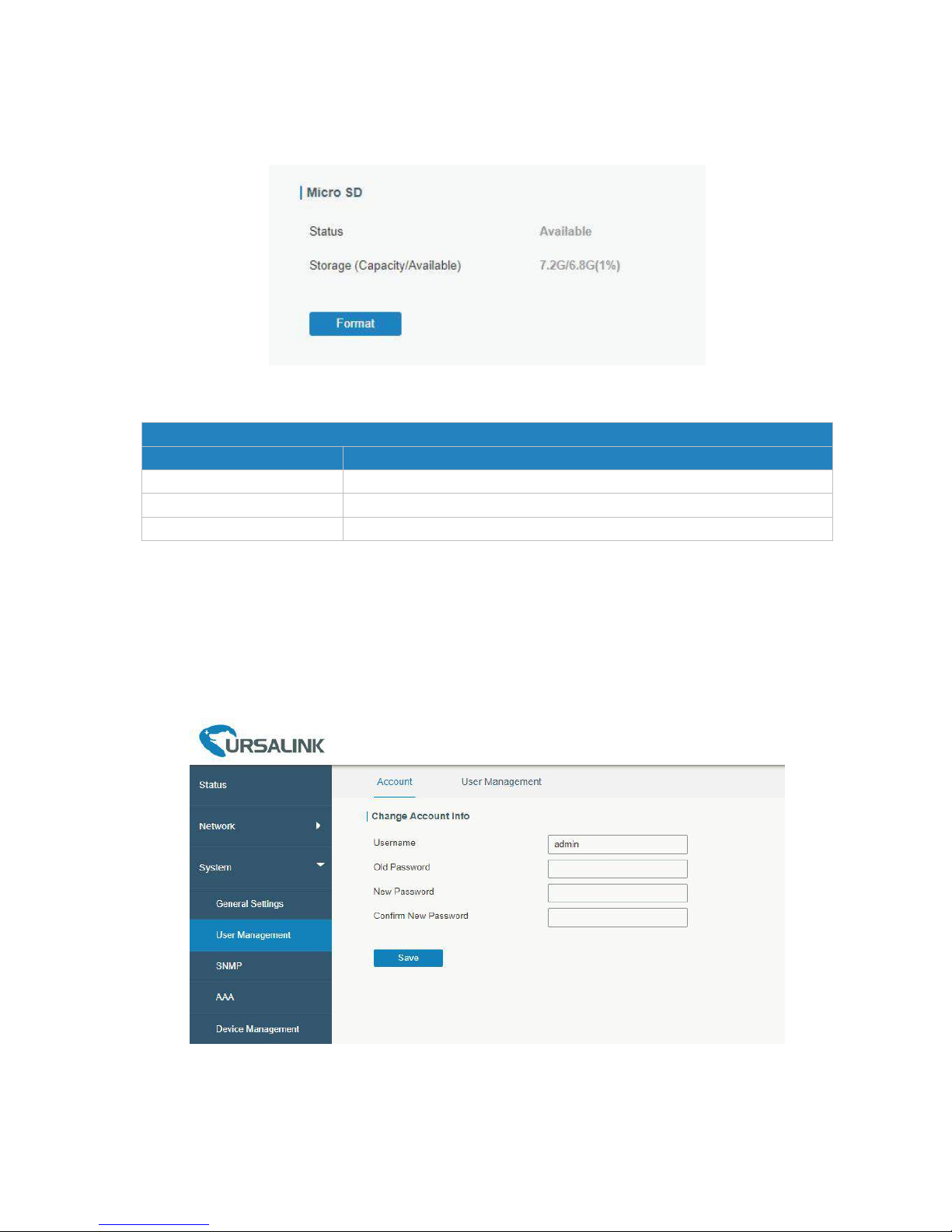
UR52 & UR55 User Guide
88
4.3.1.6 Storage
You can view Micro SD card information on this page.
Figure 4-3-1-8
Storage
Item
Description
Status
Show the status of Micro SD card, such as “Available” or “Not Inserted”.
Storage (Capacity/Available)
The total capacity of the Micro SD Card
。
Format
Format the Micro SD card.
Table 4-3-1-7 Storage Information
4.3.2 User Management
4.3.2.1 Account
Here you can change the login username and password of the administrator.
Note: it is strongly recommended that you modify them for the sake of security.
Figure 4-3-1-9
Page 89
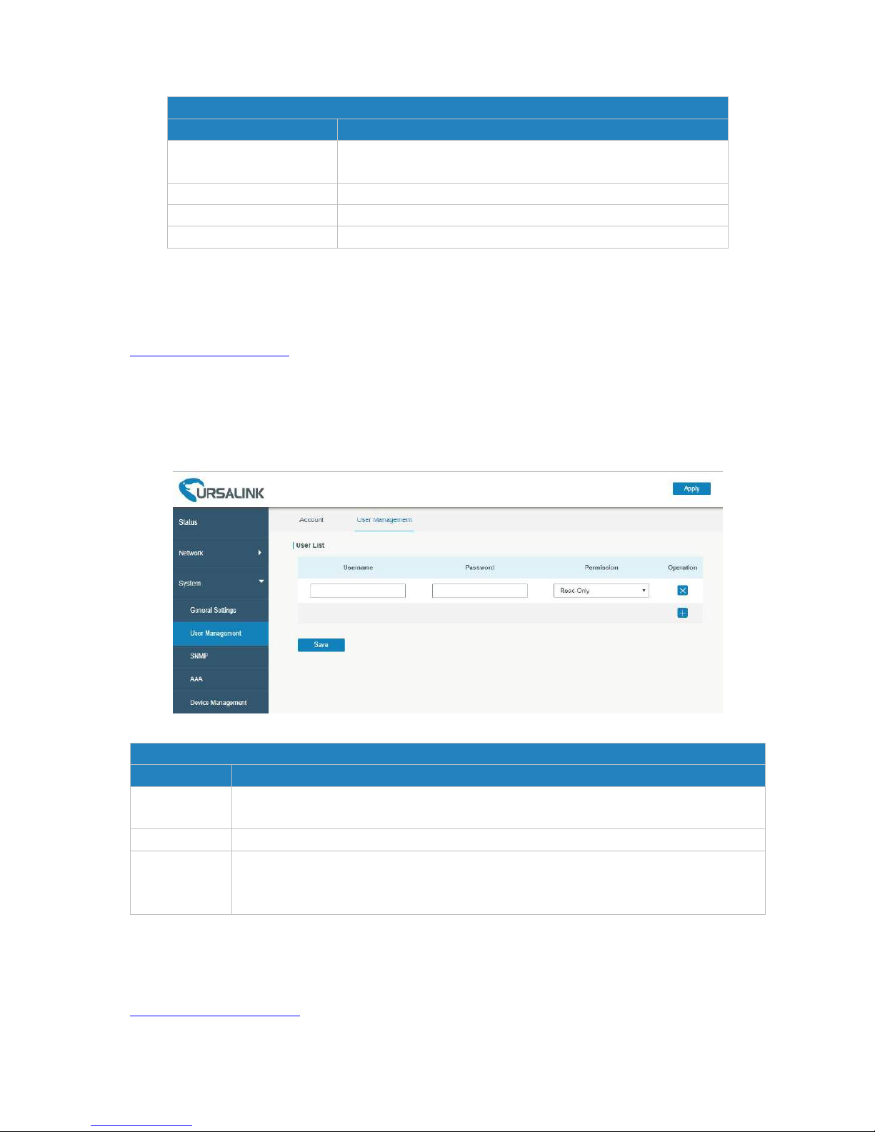
UR52 & UR55 User Guide
89
Account
Item
Description
Username
Enter a new username. You can use characters such as a-z,
0-9, "_", "-", "$". The first character can't be a digit.
Old Password
Enter the old password.
New Password
Enter a new password.
Confirm New Password
Enter the new password again.
Table 4-3-1-7 Account Settings
Related Configuration Example
Account Info Management
4.3.2.2 User Management
This section describes how to create common user accounts.
The common user permission includes Read-Only and Read-Write.
Figure 4-3-2-1
User Management
Item
Description
Username
Enter a new username. You can use characters such as a-z, 0-9, "_", "-", "$". The first
character can't be a digit.
Password
Set password.
Permission
Select user permission from “Read-Only” and “Read-Write”.
- Read-Only: users can only view the configuration of router in this level.
- Read-Write: users can view and set the configuration of router in this level.
Table 4-3-2-1 User Management
Related Configuration Example
Common User Management
Page 90
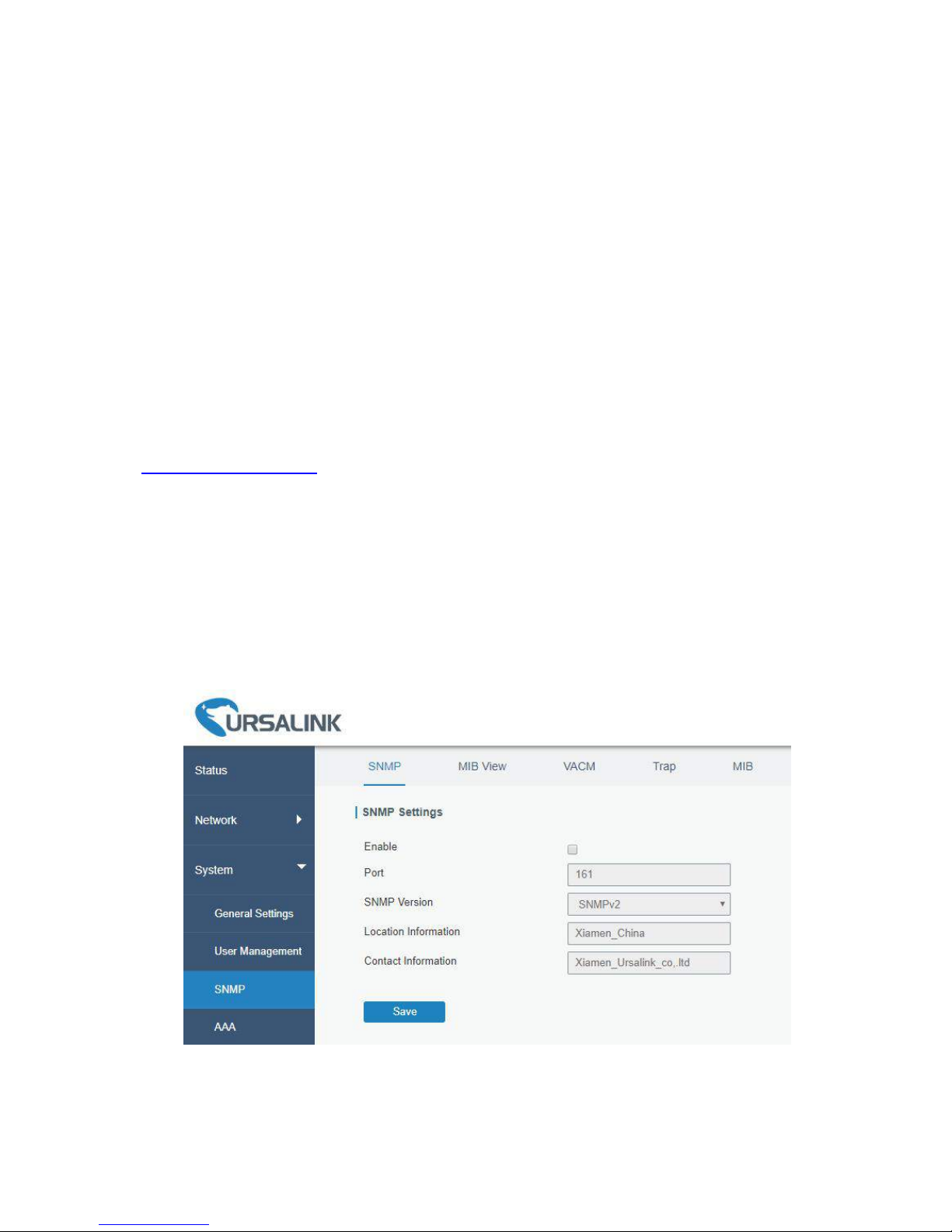
UR52 & UR55 User Guide
90
4.3.3 SNMP
SNMP is widely used in network management for network monitoring. SNMP exposes management data
with variables form in managed system. The system is organized in a management information base (MIB)
which describes the system status and configuration. These variables can be remotely queried by
managing applications.
Configuring SNMP in networking, NMS, and a management program of SNMP should be set up at the
Manager.
Configuration steps are listed as below for achieving query from NMS:
1. Enable SNMP setting.
2. Download MIB file and load it into NMS.
3. Configure MIB View.
4. Configure VCAM.
Related Configuration Example
SNMP Application Example
4.3.3.1 SNMP
The UR52/UR55 supports SNMPv1, SNMPv2c and SNMPv3 version. SNMPv1 and SNMPv2c employ
community name authentication. SNMPv3 employs authentication encryption by username and
password.
Figure 4-4-3-1
Page 91
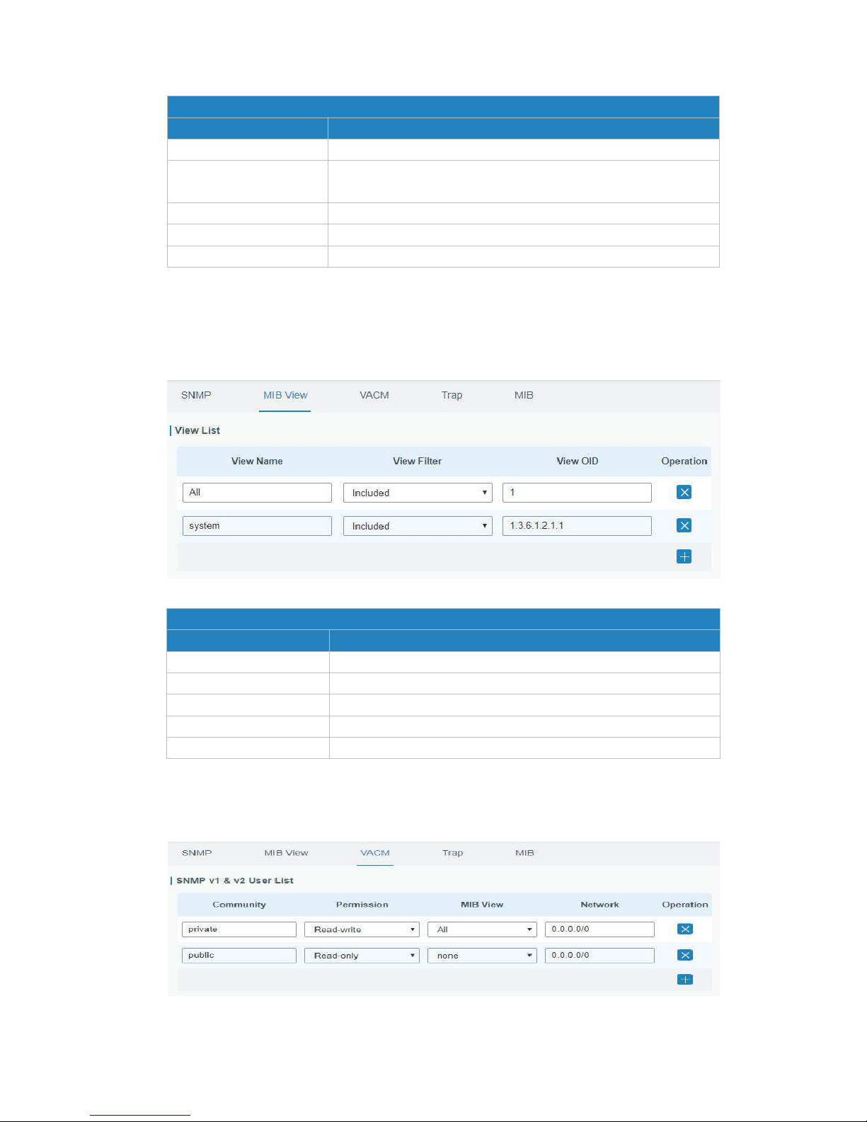
UR52 & UR55 User Guide
91
SNMP Settings
Item
Description
Enable
Enable or disable SNMP function.
Port
Set SNMP listened port. Range: 1-65535.
The default port is 161.
SNMP Version
Select SNMP version; support SNMP v1/v2c/v3.
Location Information
Fill in the location information.
Contact Information
Fill in the contact information.
Table 4-4-3-1 SNMP Parameters
4.3.3.2 MIB View
This section explains how to configure MIB view for the objects.
Figure 4-4-3-2
MIB View
Item
Description
View Name
Set MIB view's name.
View Filter
Select from "Included" and "Excluded".
View OID
Enter the OID number.
Included
You can query all nodes within the specified MIB node.
Excluded
You can query all nodes except for the specified MIB node.
Table 4-3-3-2 MIB View Parameters
4.3.3.3 VACM
This section describes how to configure VCAM parameters.
Figure 4-3-3-3
Page 92
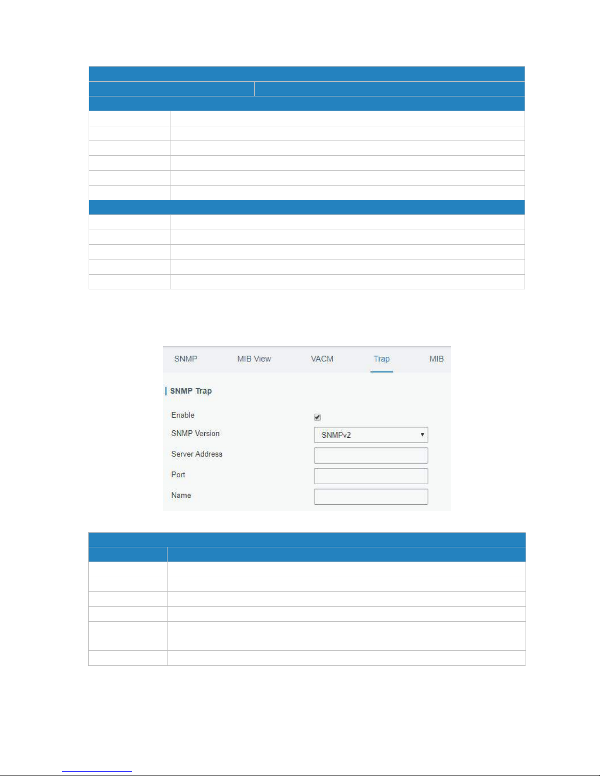
UR52 & UR55 User Guide
92
VACM
Item
Description
SNMP v1 & v2 User List
Community
Set the community name.
Permission
Select from "Read-Only" and "Read-Write".
MIB View
Select an MIB view to set permissions from the MIB view list.
Network
The IP address and bits of the external network accessing the MIB view.
Read-Write
The permission of the specified MIB node is read and write.
Read-Only
The permission of the specified MIB node is read only.
SNMP v3 User List
Group Name
Set the name of SNMPv3 group.
Security Level
Select from "NoAuth/NoPriv", "Auth/NoPriv", and " Auth/Priv".
Read-Only View
Select an MIB view to set permission as "Read-only" from the MIB view list.
Read-Write View
Select an MIB view to set permission as "Read-write" from the MIB view list.
Inform View
Select an MIB view to set permission as "Inform" from the MIB view list.
Table 4-3-3-3 VACM Parameters
4.3.3.4 Trap
This section explains how to enable network monitoring by SNMP trap.
Figure 4-3-3-4
SNMP Trap
Item
Description
Enable
Enable or disable SNMP Trap function.
SNMP Version
Select SNMP version; support SNMP v1/v2c/v3.
Server Address
Fill in NMS's IP address or domain name.
Port
Fill in UDP port. Port range is 1-65535. The default port is 162.
Name
Fill in the group name when using SNMP v1/v2c; fill in the username when using
SNMP v3.
Auth/Priv Mode
Select from "NoAuth & No Priv", "Auth & NoPriv", and "Auth & Priv".
Table 4-3-3-4 Trap Parameters
Page 93
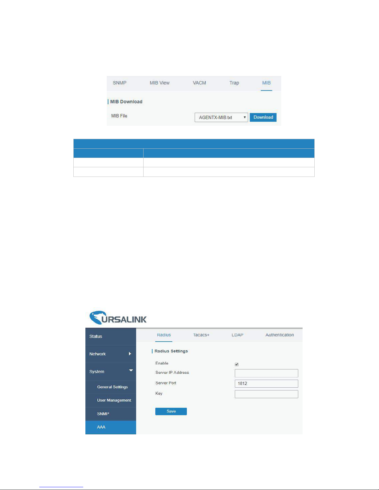
UR52 & UR55 User Guide
93
4.3.3.5 MIB
This section describes how to download MIB files. The last MIB file “URSA-ROUTER-MIB.txt” is for the
UR52/UR55 router.
Figure 4-3-3-5
MIB
Item
Description
MIB File
Select the MIB file you need.
Download
Click "Download" button to download the MIB file to PC.
Table 4-3-3-5 MIB Download
4.3.4 AAA
AAA access control is used for visitors control and the available corresponding services once access is
allowed. It adopts the same method to configure three independent safety functions. It provides
modularization methods for following services:
- Authentication: verify if the user is qualified to access to the network.
- Authorization: authorize related services available for the user.
- Charging: record the utilization of network resources.
-
4.3.4.1 Radius
Using UDP for its transport, Radius is generally applied in various network environments with higher
requirements of security and permission of remote user access.
Figure 4-3-4-1
Page 94
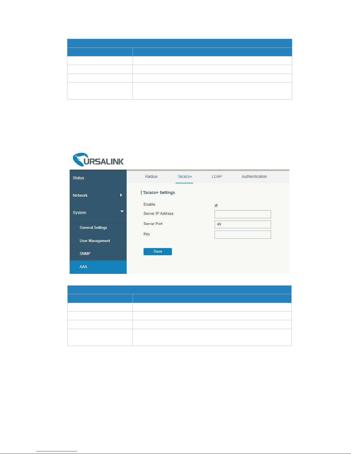
UR52 & UR55 User Guide
94
Radius
Item
Description
Enable
Enable or disable Radius.
Server IP Address
Fill in the Radius server IP address/domain name.
Server Port
Fill in the Radius server port. Range: 1-65535.
Key
Fill in the key consistent with that of Radius server in order to
get connected with Radius server.
Table 4-3-4-1 Radius Parameters
4.3.4.2 TACACS+
Using TCP for its transport, TACACS+ is mainly used for authentication, authorization and charging of the
access users and terminal users by adopting PPP and VPDN.
Figure 4-3-4-2
TACACS+
Item
Description
Enable
Enable or disable TACACS+.
Server IP Address
Fill in the TACACS+ server IP address/domain name.
Server Port
Fill in the TACACS+ server port. Range: 1-65535.
Key
Fill in the key consistent with that of TACACS+ server in order
to get connected with TACACS+ server.
Table 4-3-4-2 TACACS+ Parameters
4.3.4.3 LDAP
A common usage of LDAP is to provide a central place to store usernames and passwords. This allows
many different applications and services to connect the LDAP server to validate users.
LDAP is based on a simpler subset of the standards contained within the X.500 standard. Because of this
relationship, LDAP is sometimes called X.500-lite as well.
Page 95
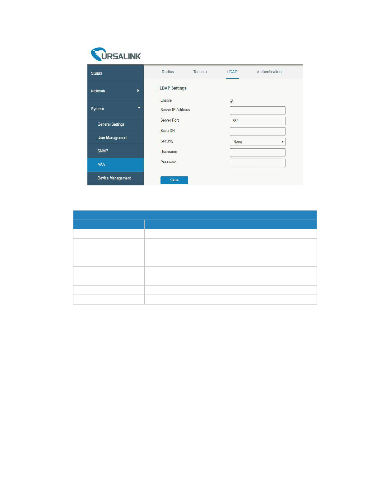
UR52 & UR55 User Guide
95
Figure 4-3-4-3
LDAP
Item
Description
Enable
Enable or Disable LDAP.
Server IP Address
Fill in the LDAP server's IP address/domain name. The
maximum count is 10.
Server Port
Fill in the LDAP server's port. Range: 1-65535
Base DN
The top of LDAP directory tree.
Security
Select secure method from "None", "StartTLS" and "SSL".
Username
Enter the username to access the server.
Password
Enter the password to access the server.
Table 4-3-4-3 LDAP Parameters
4.3.4.4 Authentication
AAA supports the following authentication ways:
- None: uses no authentication, generally not recommended.
- Local: uses the local username database for authentication.
Advantages: rapidness, cost reduction.
Disadvantages: storage capacity limited by hardware.
- Remote: has user’s information stored on authentication server. Radius, TACACS+ and LDAP supported
for remote authentication.
When radius, TACACS+, and local are configured at the same time, the priority level is: 1 >2 >3.
Page 96
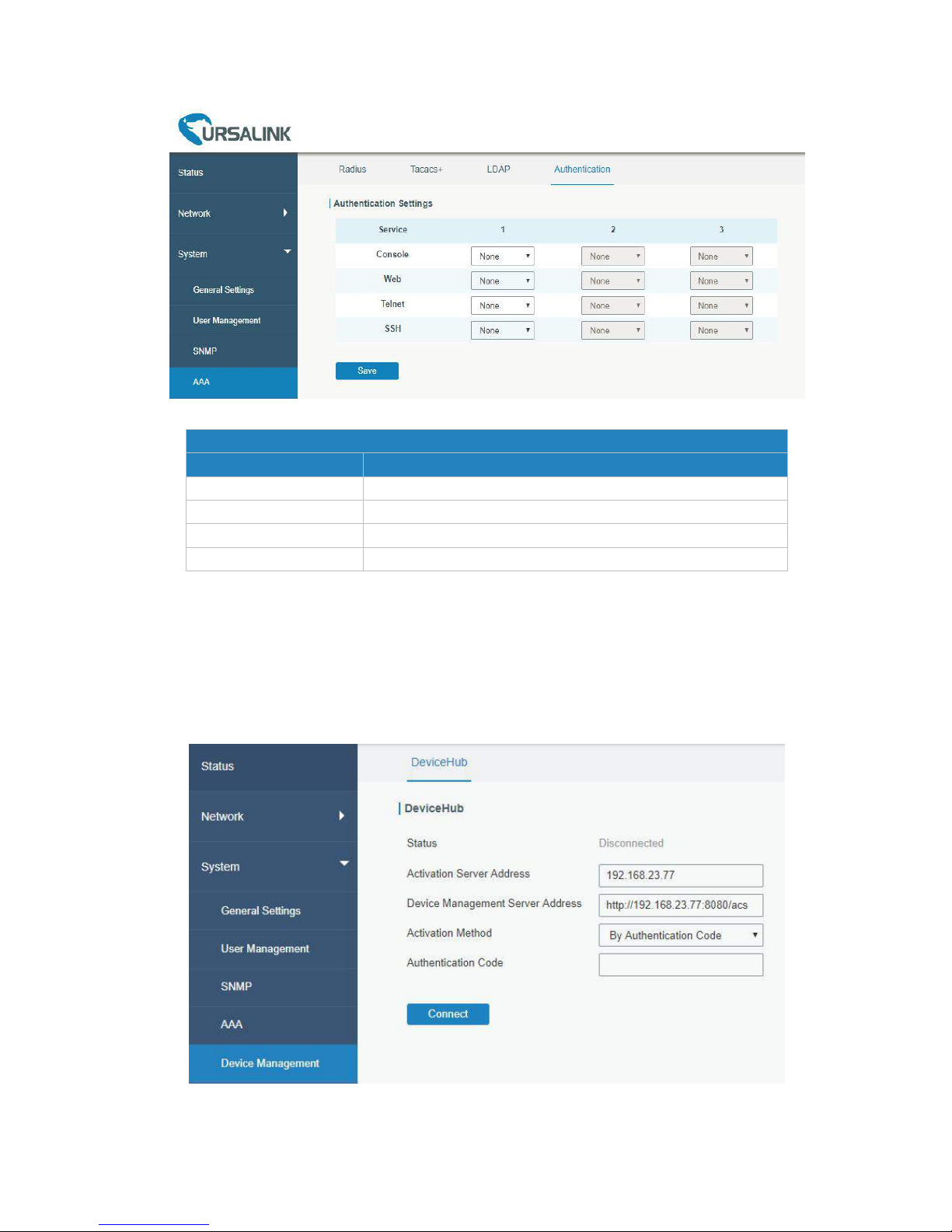
UR52 & UR55 User Guide
96
Figure 4-3-4-4
Authentication
Item
Description
Console
Select authentication for Console access.
Web
Select authentication for Web access.
Telnet
Select authentication for Telnet access.
SSH
Select authentication for SSH access.
Table 4-3-4-4 Authentication Parameters
4.3.5 Device Management
You can connect the device to the Ursalink DeviceHub on this page so as to manage the router centrally and
remotely.
Figure 4-3-5-1
Page 97
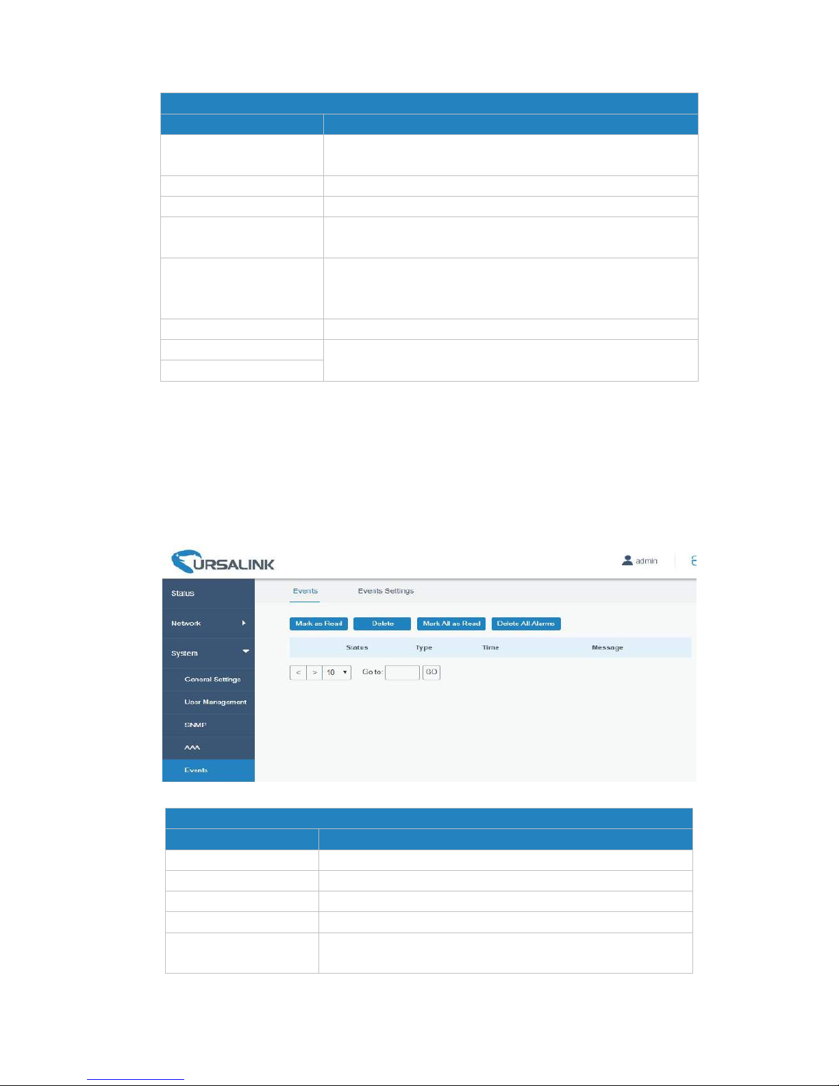
UR52 & UR55 User Guide
97
DeviceHub
Item
Description
Status
Show the connection status between the router and the
DeviceHub.
Disconnected
Click this button to disconnect the router from the DeviceHub.
Activation Server Address
IP address or domain of the DeviceHub.
DeviceHub Server
Address
The URL address for the device to connect to the DeviceHub,
e.g. http://220.82.63.79:8080/acs.
Activation Method
Select activation method to connect the router to the
DeviceHub server, options are "By Authentication ID" and "By
ID".
Authentication Code
Fill in the authentication code generated from the DeviceHub.
ID
Fill in the registered DeviceHub account (email) and password.
Password
Table 4-3-5-1
4.3.6 Events
Event feature is capable of sending alerts by Email when certain system events occur.
4.3.6.1 Events
You can view alarm messages on this page.
Figure 4-3-6-1
Events
Item
Description
Mark as Read
Mark the selected event alarm as read.
Delete
Delete the selected event alarm.
Mark All as Read
Mark all event alarms as read.
Delete All Alarms
Delete all event alarms.
Status
Show the reading status of the event alarms, such as “Read”
and “Unread”.
Page 98
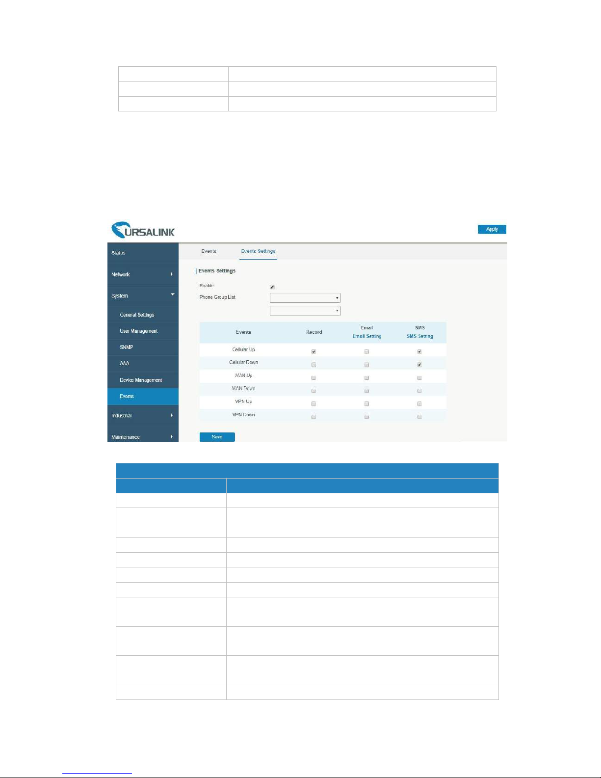
UR52 & UR55 User Guide
98
Type
Show the event type that should be alarmed.
Time
Show the alarm time.
Message
Show the alarm content.
Table 4-3-6-1 Events Parameters
4.3.6.2 Events Settings
In this section, you can decide what events to record and whether you want to receive email and SMS
notifications when any change occurs.
Figure 4-3-6-2
Event Settings
Item
Description
Enable
Check to enable "Events Settings".
Cellular Up
Cellular network is connected.
Cellular Down
Cellular network is disconnected.
WAN Up
Ethernet cable is connected to WAN port.
WAN Down
Ethernet cable is disconnected to WAN port.
VPN Up
VPN is connected.
VPN Down
VPN is disconnected.
Record
The relevant content of event alarm will be recorded on
"Event" page if this option is checked.
Email
The relevant content of event alarm will be sent out via email if
this option is checked.
Email Setting
Click and you will be redirected to the page "SMTP" to
configure the sender's & recipients' info.
SMS
The relevant content of event alarm will be sent out via SMS if
Page 99
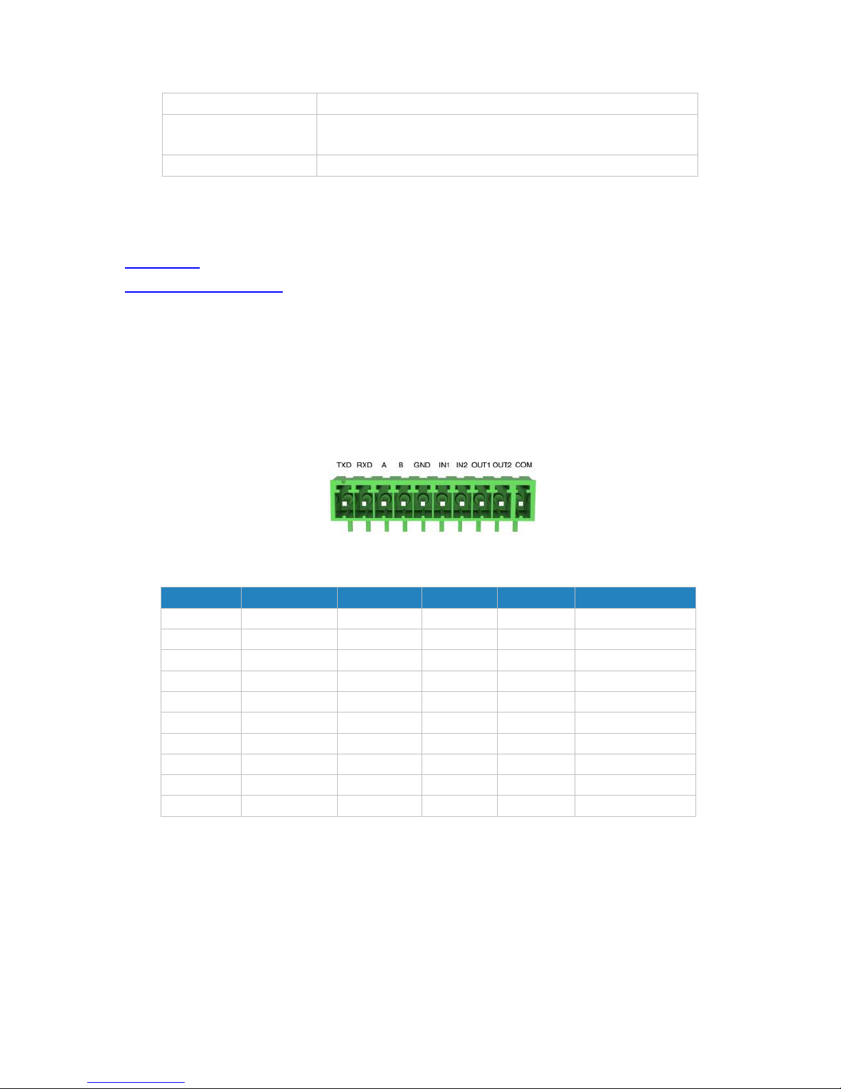
UR52 & UR55 User Guide
99
this option is checked.
SMS Setting
Click and you will be redirected to the page of "Phone" to
configure phone group list.
Phone Group List
Select phone group to receive SMS alarm.
Table 4-3-6-2 Events Parameters
Related Topics
Email Setting
Events Application Example
4.4 Industrial Interface
The UR52/UR55 router is capable of connecting with terminals through industrial interfaces so as to
realize wireless communication between terminals and remote data center.
There are two types of the router’s industrial interface: serial port (RS232 and RS485) and I/O (digital
input and digital output).
Figure 4-4-1 Pinouts
Table 4-4-1 Pinouts Definition
RS232 adopts full-duplex communication. It’s generally used for communication within 20m.
RS485 adopts half-duplex communication to achieve transmission of serial communication data with
distance up to 1200 m.
Digital input of I/O interface is a logical variable or switch variable with only two values of 0 and 1. “0”
refers to low level and “1” refers to high level .
PIN
RS232*1
RS485*1
DI*2
DO*2
Description
1
TXD
---
---
---
Transmit Data
2
RXD
---
---
---
Receive Data
3
---A---
---
Data +
4
---B---
---
Data -
5
GND
---
GND
---
Ground
6
---
---
IN1
---
Digital Input1
7
---
---
IN2
---
Digital Input2
8
---
---
---
OUT1
Digital Output1
9
---
---
---
OUT2
Digital Output2
10
---
---
---
COM
Common Ground
Page 100
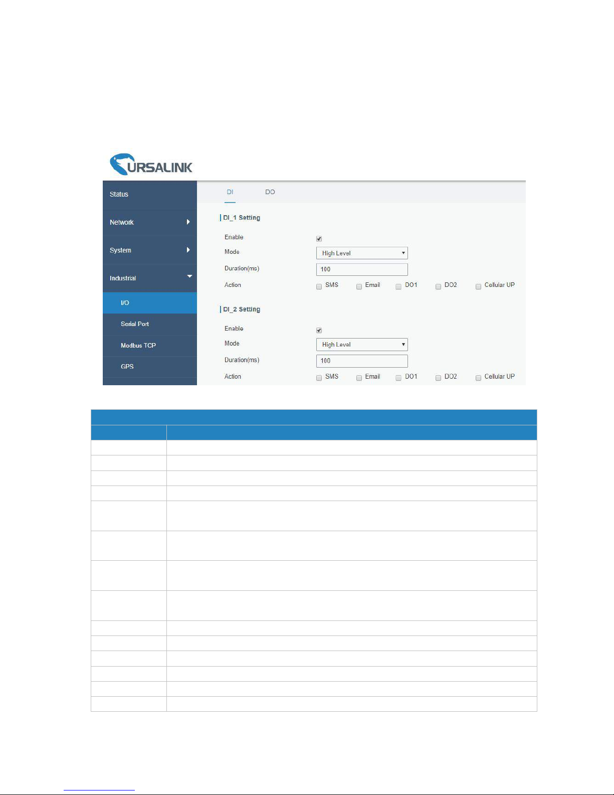
UR52 & UR55 User Guide
100
4.4.1 I/O
4.4.1.1 DI
This section explains how to configure monitoring condition on digital input, and take certain actions once
the condition is reached.
Figure 4-4-1-1
DI
Item
Description
Enable
Enable or disable DI.
Mode
Options are "High Level", "Low Level", and "Counter".
Duration (ms)
Set the duration of high/low level in digital input. Range: 1-10000.
Condition
Select from "Low->High", and "High-> Low".
Low->High
The counter value will increase by 1 if digital input's status changes from low level to
high level.
High->Low
The counter value will increase by 1 if digital input's status changes from high level to
low level.
Counter
The system will take actions accordingly when the counter value reach the preset
one, and then reset the counter value to 0. Range: 1-100.
Action
Select the corresponding actions that the system will take when digital input mode
meets the preset condition or duration.
SMS
Check to enable SMS alarm.
Phone
Set phone number to receive SMS alarm.
Content
Set the content of SMS alarm.
Email
Check to enable Email alarm.
DO1
Control output status of DO1.
DO2
Control output status of DO2.
 Loading...