

Ursalink UG87 User Manual

UG87 User Guide
2
Document
Description
Ursalink UG87 Datasheet
Datasheet for the Ursalink UG87 industrial
LoRaWAN gateway.
Ursalink UG87 Quick Start Guide
Quick Installation Guide for the Ursalink
UG87 industrial LoRaWAN gateway.
Preface
Thanks for choosing Ursalink UG87 industrial LoRaWAN gateway. The UG87 industrial
LoRaWAN gateway delivers tenacious connection over network with full-featured design
such as automated failover/failback, extended operating temperature, dual SIM cards,
hardware watchdog, VPN, Gigabit Ethernet and beyond.
This guide shows you how to configure and operate the UG87 industrial LoRaWAN gateway.
You can refer to it for detailed functionality and gateway configuration.
Readers
This guide is mainly intended for the following users:
- Network Planners
- On-site technical support and maintenance personnel
- Network administrators responsible for network configuration and maintenance
© 2017 Xiamen Ursalink Technology Co., Ltd.
All rights reserved.
All information in this user guide is protected by copyright law. Whereby, no organization or
individual shall copy or reproduce the whole or part of this user guide by any means without
written authorization from Xiamen Ursalink Technology Co., Ltd.
Products Covered
This guide explains how to configure the following devices:
• Ursalink UG87 LoRaWAN gateway
Related Documents
UG87 User Guide
3
Date
Doc Version
Description
July 13, 2019
V1.1
Initial version
Aug. 6, 2019
V1.2
Add New Feature:
1. Python Development
2. Send data to LoRaWAN nodes
Sep. 25, 2019
V1.3
Add New Feature:
Modbus RTU Data Transmission (Applicable for
UC11-N1 and UC1152)
Oct. 14, 2019
V1.4
Add New Feature: Support 16 LoRa channels
Nov. 22, 2019
V1.5
Add New Feature:
1. Packet Forwarder with Multi-Destination
2. MQTT TLS certified mode
May 12, 2020
V1.6
1. Delete LAN and VLAN configuration
2. Default IP change from 192.168.1.1 to
192.168.23.150
3. New Function: Add devices in bulk
Declaration of Conformity
UG87 is in conformity with the essential requirements and other relevant provisions of the
CE, FCC, and RoHS.
For assistance, please contact
Ursalink technical support:
Email: support@ursalink.com
Tel.: 86-592-5023060
Fax: 86-592-5023065
Revision History

4
Contents
UG87 User Guide
Chapter 1 Product Introduction
1.1 Overview
1.2 Advantages
1.3 Specifications
1.4 Dimensions (mm)
Chapter 2 Access to Web GUI
2.1 PC Configuration for Web GUI Access to gateway
2.2 Access to Web GUI of gateway
Chapter 3 Web Configuration
3.1 Status
3.1.1 Overview
3.1.2 Packet Forwarder
3.1.3 Cellular
3.1.4 Network
3.1.5 WLAN (Only Applicable to Wi-Fi Version)
3.1.6 VPN
3.1.7 Host List
3.2 LoRaWAN
3.2.1 Packet Forwarder
3.2.2 Network Server
3.2.2.3 Profiles
3.3 Network
3.3.1 Interface
3.3.2 Firewall
...............................................................................................................................
............................................................................................................................
........................................................................................................................
...................................................................................................................................
.....................................................................................................................
...................................................................................................................
...........................................................................................................................
....................................................................................................................
............................................................................................................................
3.2.1.1 General
3.2.1.3 Radios (Dual-module)
3.2.1.4 Advanced
3.2.1.5 Custom
3.2.1.6 Traffic
3.2.2.1 General
3.2.2.2 Application
..........................................................................................................................
3.2.2.4 Device
3.2.2.5 Packets
..............................................................................................................................
...................................................................................................................
3.3.1.1 Port
3.3.1.2 WLAN (Only Applicable to Wi-Fi Version)
3.3.1.3 Cellular
3.3.1.4 Loopback
.....................................................................................................................
3.3.2.1 Security
3.3.2.2 ACL
3.3.2.3 DMZ
3.3.2.4 Port Mapping
3.3.2.5 MAC Binding
.........................................................................................................
...............................................................................................................
...........................................................................................................
..........................................................................................
...........................................................................................................
..................................................................................................................
....................................................................................................
....................................................................................................
.........................................................................................................
..................................................................................
......................................................................................................
..........................................................................................................
............................................................................................................
........................................................................................................
.........................................................................................................
...................................................................................................
...........................................................................................................
..........................................................................................................
...............................................................................................................
..........................................................................................................
.......................................................................................................
.........................................................................................................
................................................................................................................
...............................................................................................................
................................................................................................
.................................................................................................
............................................................
..............................................................
...................................................
7
7
7
8
10
11
11
12
14
14
14
14
16
17
18
19
20
21
22
22
25
27
28
29
30
30
32
33
33
34
37
37
37
40
42
45
46
46
47
48
49
50

UG87 User Guide
5
3.3.3 QoS
3.3.4 DHCP
...........................................................................................................................
........................................................................................................................
3.3.4.1 DHCP Server
3.3.4.2 DHCP Relay
3.3.5 DDNS
........................................................................................................................
3.3.6 Link Failover
3.3.6.1 SLA
3.3.6.2 Track
3.3.6.3 VRRP
3.3.6.4 WAN Failover
3.3.7 VPN
...........................................................................................................................
3.3.7.1 DMVPN
3.3.7.2 IPSec
3.3.7.3 GRE
3.3.7.4 L2TP
3.3.7.5 PPTP
3.3.7.6 OpenVPN Client
3.3.7.7 OpenVPN Server
3.3.7.8 Certifications
3.4 System
.................................................................................................................................
3.4.1 General Settings
3.4.1.1 General
3.4.1.2 System Time
3.4.1.3 SMTP
3.4.1.4 Phone
3.4.1.5 Email
3.4.2 User Management
3.4.2.1 Account
3.4.2.2 User Management
3.4.3 SNMP
........................................................................................................................
3.4.3.1 SNMP
3.4.3.2 MIB View
3.4.3.3 VACM
3.4.3.4 Trap
3.4.3.5 MIB
3.4.4 AAA
..........................................................................................................................
3.4.4.1 RADIUS
3.4.4.2 TACACS+
3.4.4.3 LDAP
3.4.4.4 Authentication
3.4.5 Device Management
3.4.6 Events
.......................................................................................................................
3.4.6.1 Events
3.4.6.2 Events Settings
..................................................................................................
...................................................................................................
.............................................................................................................
.................................................................................................................
..............................................................................................................
..............................................................................................................
................................................................................................
.........................................................................................................
..............................................................................................................
................................................................................................................
...............................................................................................................
..............................................................................................................
............................................................................................
...........................................................................................
................................................................................................
......................................................................................................
.........................................................................................................
.................................................................................................
.............................................................................................................
............................................................................................................
.............................................................................................................
...................................................................................................
.........................................................................................................
........................................................................................
............................................................................................................
......................................................................................................
............................................................................................................
...............................................................................................................
................................................................................................................
..........................................................................................................
........................................................................................................
..............................................................................................................
..............................................................................................
...............................................................................................
............................................................................................................
.............................................................................................
50
51
51
53
53
54
54
55
56
57
58
58
60
62
63
65
67
68
70
72
72
72
73
75
75
76
77
77
78
79
79
80
80
81
82
82
82
83
83
84
85
86
86
87

UG87 User Guide
6
3.5 Maintenance
3.5.1 Tools
3.5.1.1 Ping
3.5.1.2 Traceroute
3.5.2 Schedule
3.5.3 Log
3.5.3.1 System Log
3.5.3.2 Log Settings
3.5.4 Upgrade
3.5.5 Backup and Restore
3.5.6 Reboot
3.6 APP
......................................................................................................................................
3.6.1 Python
3.6.1.1 Python
.......................................................................................................................
.........................................................................................................................
...............................................................................................................
.....................................................................................................
...................................................................................................................
............................................................................................................................
....................................................................................................
...................................................................................................
....................................................................................................................
.................................................................................................
......................................................................................................................
......................................................................................................................
...........................................................................................................
3.6.1.2 App Manager Configuration
3.6.1.3 Python App
Chapter 4 Application Examples
...................................................................................................
......................................................................................................
4.1 Packet Forwarder Configuration
4.2 Application Configuration
..................................................................................................
4.3 Device Profiles Configuration
4.4 Device Configuration
4.5 Send Data to Device
4.6 Restore Factory Defaults
4.6.1 Via Web Interface
4.6.2 Via Hardware
4.7 Firmware Upgrade
4.8 Cellular Connection
........................................................................................................
.........................................................................................................
..................................................................................................
..................................................................................................
.........................................................................................................
............................................................................................................
..........................................................................................................
4.9 Dual SIM Backup Application Example
4.10 Wi-Fi Application Example
4.10.1 AP Mode
4.10.2 Client Mode
..............................................................................................................
.........................................................................................................
........................................................................
........................................................................................
..........................................................................................
............................................................................
.............................................................................................
88
88
88
88
89
89
90
90
91
92
93
93
93
94
94
95
96
96
97
101
104
108
112
112
113
114
115
117
119
119
120
UG87 User Guide
7
Chapter 1 Product Introduction
1.1 Overview
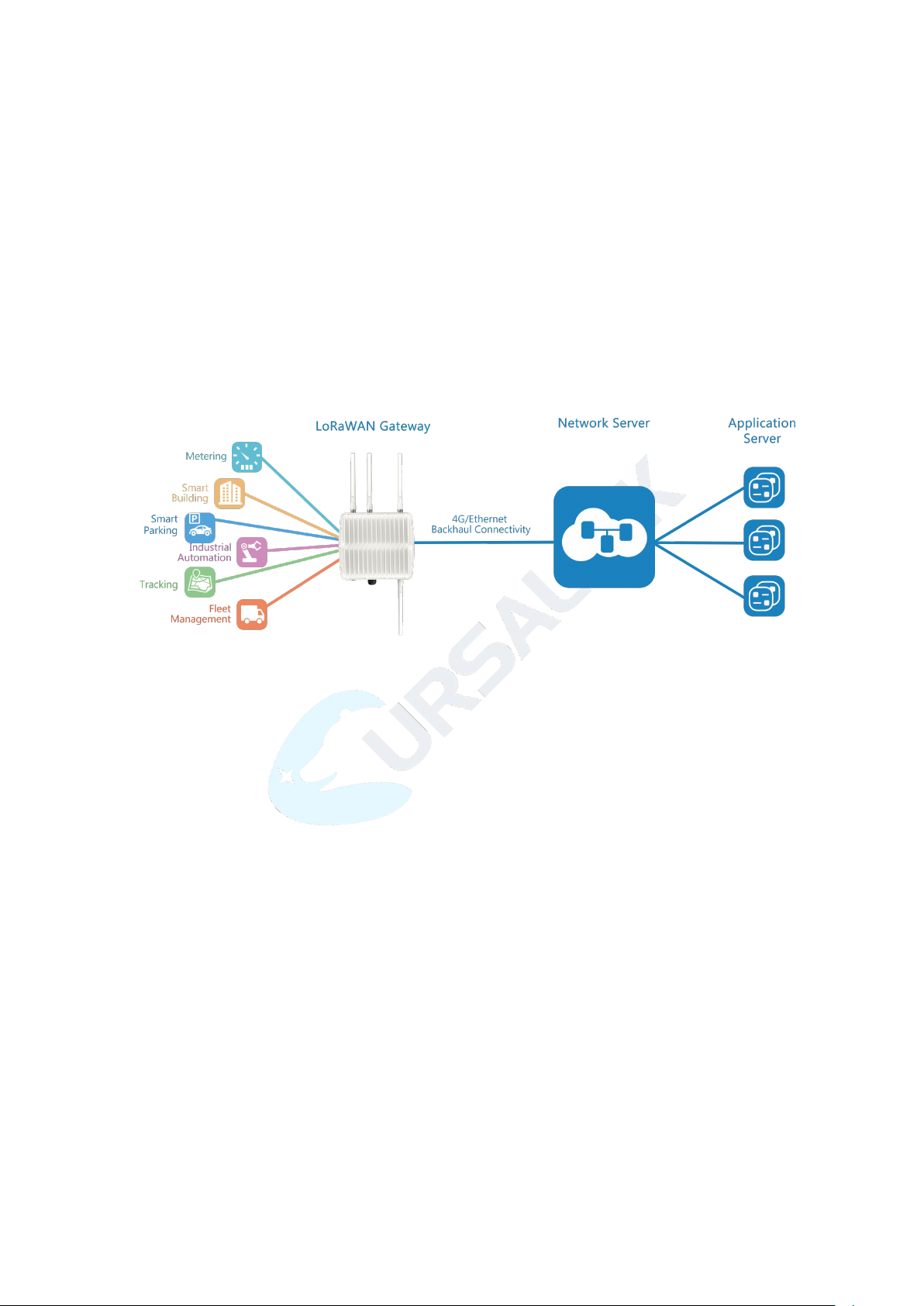
Ursalink UG87 is an industrial LoRaWAN gateway with embedded intelligent software
features designed for multifarious M2M/IoT applications. Options like cellular network or
Wi-Fi provide drop-in connectivity for operators and make a giant leap in maximizing uptime.
Adopting high-performance industrial platform of 64-bit CPU and wireless module, the UG87
enables you to scale up M2M application combining data within limited time and budget.
The UG87 is particularly ideal for smart city, smart agriculture, building automation, digital
factory, environment protection, water conservancy and so on.
Figure 1-1
1.2 Advantages
Benefits
- Built-in industrial CPU and big memory;
- Ethernet, 2.4GHz/5GHz Wi-Fi and global 2G/3G/LTE options make it easy to get
connected
- Embedded network server and compliant with several third party network servers
- MQTT, HTTP or HTTPS protocol for data transmission to application server
- Embedded GPS module for high-precision time synchronization
- Rugged enclosure, optimized for wall or pole mounting
- 3-year warranty included
Security & Reliability
- Automated failover/failback between Ethernet and Cellular (dual SIM)
- Enable unit with security frameworks like IPsec/OpenVPN/GRE/L2TP/PPTP/ DMVPN
- Embedded hardware watchdog to automatically recover from various failure and ensure
highest level of availability

UG87 User Guide
8
Hardware System
CPU
800MHz, 64-bit ARM Cortex-A53
Memory
8 GB Flash, 512 MB DDR3 RAM
Storage
1 × M.2 slot supports SATA M.2 SSD
LoRaWAN
Connectors
1 × 50 Ω N-Type (Center pin: Female) for 8-channel model
2 × 50 Ω N-Type (Center pin: Female) for 16-channel model
Channel
8 or 16
Frequency Band
Supports EU 863-870, US 902-928, EU 433, AU 915-928, CN
470-510 IN865 and KR 920-923 Band
Sensitivity
-140dBm Sensitivity @292bps
Output Power
27dBm Max
- Establish a secured mechanism on centralized authentication and features authorization
of device access by supporting AAA (TACACS+, RADIUS, LDAP, local authentication) and
multiple levels of user authority
Easy Maintenance
- Ursalink DeviceHub provides easy setup, mass configuration, and centralized
management of remote devices
- The user-friendly web interface design and various upgrading options help administrator
to manage the device as easy as pie
- WEB GUI and CLI enable the admin to achieve quick configuration and simple
management among a large quantity of devices
- Users can efficiently manage the remote devices on the existing platform through the
industrial standard SNMP
Capabilities
- Link remote devices in an environment where communication technologies are
constantly changing
- Industrial 64-bit ARM Cortex-A53 processor, high-performance operating up to 800MHz
with low power consumption, and 512 MB memory available to support more
applications
- Support wide operating temperature ranging from -40°C to 70°C/-40°F to 158°F
1.3 Specifications

UG87 User Guide
9
Physical Characteristics
Ingress Protection
IP67
Protocol
V1.0 Class A/Class C and V1.0.2 Class A/Class C
Ethernet
Ports
1 × RJ-45 (PoE PD)
Physical Layer
10/100/1000 Base-T (IEEE 802.3)
Data Rate
10/100/1000 Mbps (auto-sensing)
Interface
Auto MDI/MDIX
Mode
Full or half duplex (auto-sensing)
Cellular Interfaces (Optional)
Connectors
1 × 50 Ω N-Type (Center pin: Female)
SIM Slots
2
Wi-Fi Interfaces (Optional)
Connectors
1 × 50 Ω N-Type (Center PIN: Female)
Standards
IEEE 802.11 b/g/n/ac
Tx Power
802.11b: 16 dBm +/-1.5 dBm (11 Mbps)
802.11g: 15 dBm +/-1.5 dBm (54 Mbps)
802.11n@2.4 GHz: 14 dBm +/-1.5 dBm (MCS7) 802.11n@5
GHz: 11 dBm +/-2 dBm (MCS7) 802.11ac@5 GHz: 10 dBm
+/-2 dBm (MCS9)
GPS
Connectors
1 × 50 Ω N-Type (Center PIN: Female)
Software
Network Protocols
PPP, PPPoE, SNMP v1/v2c/v3, TCP, UDP, DHCP, DDNS, VRRP,
HTTP, HTTPS, DNS, SNTP, Telnet, SSH, MQTT, etc.
VPN Tunnel
DMVPN/IPsec/OpenVPN/PPTP/L2TP/GRE
Access Authentication
CHAP/PAP/MS-CHAP/MS-CHAPV2
Firewall
ACL/DMZ/Port Mapping/MAC Binding
Management
Web, CLI, SMS, On-demand dial up
Reliability
VRRP, Dual SIM Backup
Power Supply and Consumption
Connector
1 × 802.3af/at PoE input
Consumption
Typical 4.9W, Max 6.5 W (8 channels)
Typical 6 W, Max 8.2 W (16 channels)
UG87 User Guide
10
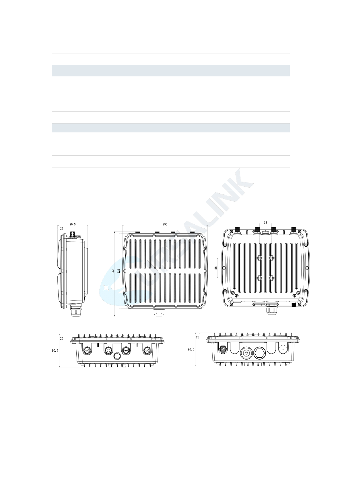
Dimensions
256 x 226 x 90.5 mm
Mounting
Wall or Pole Mounting
Others
Reset Button
1 × RST
LED Indicators
1 × PWR, 1 × SYS, 1 x L1 , 1 × L2
Built-in
Watchdog, RTC, Timer
Certifications
RoHS, CE, FCC
Environmental
Operating Temperature
-40°C to +70°C (-40°F to +158°F) Reduced cellular
performance above 60°C
Storage Temperature
-40°C to +85°C (-40°F to +185°F)
Ethernet Isolation
1.5 kV RMS
Relative Humidity
0% to 95% (non-condensing) at 25°C/77°F
1.4 Dimensions (mm)
UG87 User Guide
11
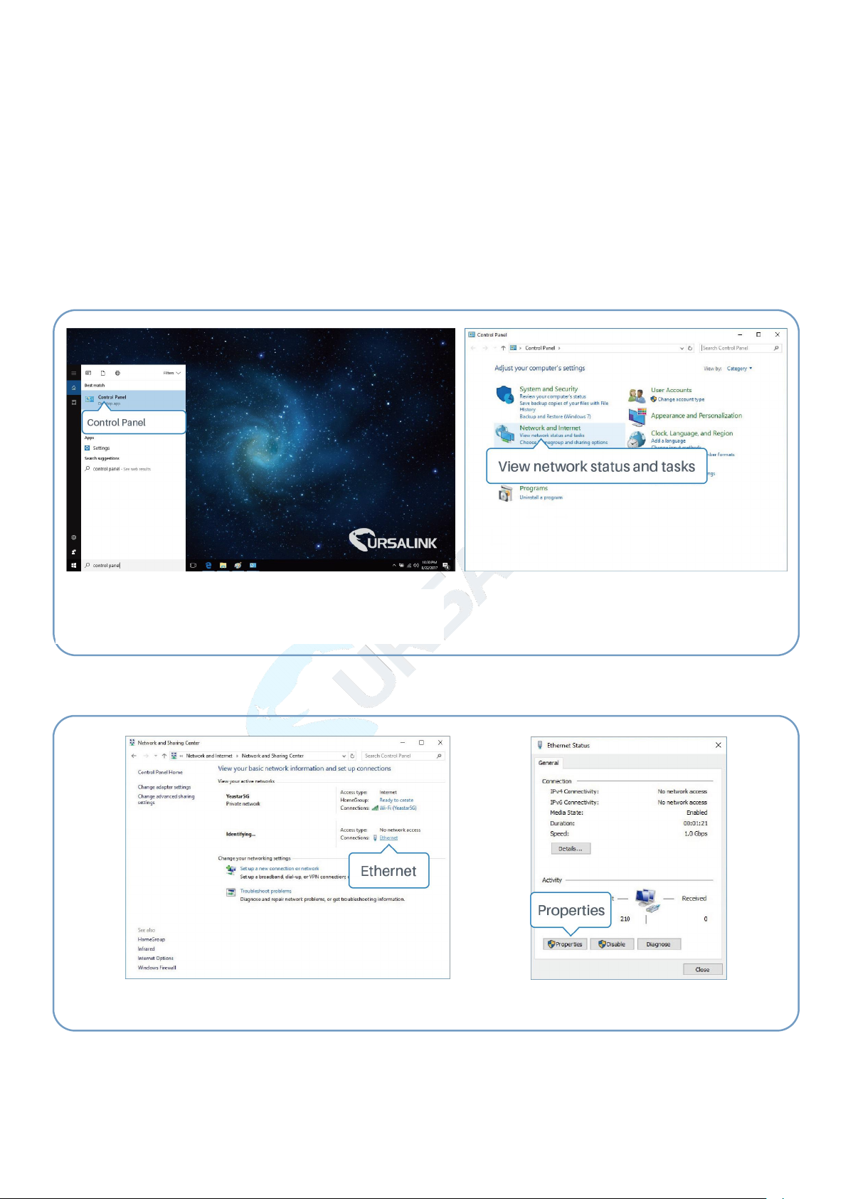
①Click "Search Box" to search "Control Panel" on
the Windows 10 taskbar.
② Click “Control Panel” to open it, and then
click “View network status and tasks”.
④ Click "Properties".
③ Click "Ethernet" (May have different name).
Chapter 2 Access to Web GUI
This chapter explains how to access to Web GUI of the UG87.
2.1 PC Configuration for Web GUI Access to gateway
Please connect PC to GE port of UG87 directly. PC can obtain an IP address, or you can
configure a static IP address manually. The following steps are based on Windows 10
operating system for your reference.
The following steps are based on Windows 10 operating system for your reference.
UG87 User Guide
12
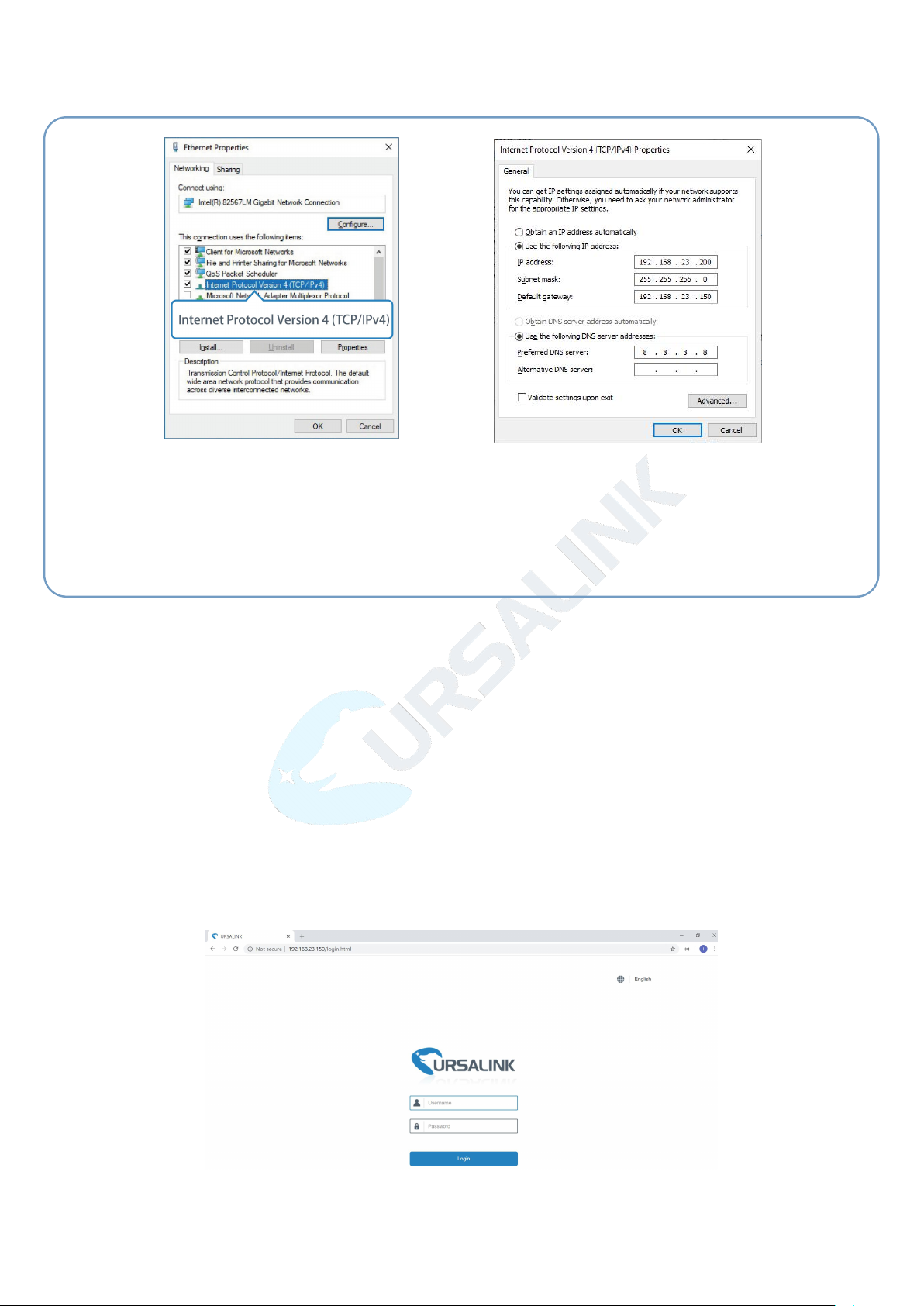
⑤ Double Click "Internet
Protocol Version 4 (TCP/IPv4)"
to configure IP address and
DNS server.
⑥ Click "Use the following IP
address" to assign a static IP
manually within the same subnet of
the gateway.
(Note: remember to click “OK” to finish configuration.)
2.2 Access to Web GUI of gateway
Ursalink gateway provides Web-based configuration interface for management. If this is the
first time you configure the gateway, please use the default settings below.
Username: admin
Password: password
IP Address: 192.168.23.150
DHCP Server: Enabled
1. Start a Web browser on your PC (Chrome and IE are recommended), type in the IP
address, and press Enter on your keyboard.
2. Enter the username, password, and click "Login".
13
If the SIM card is connected to cellular network with public IP address, you can access WEB
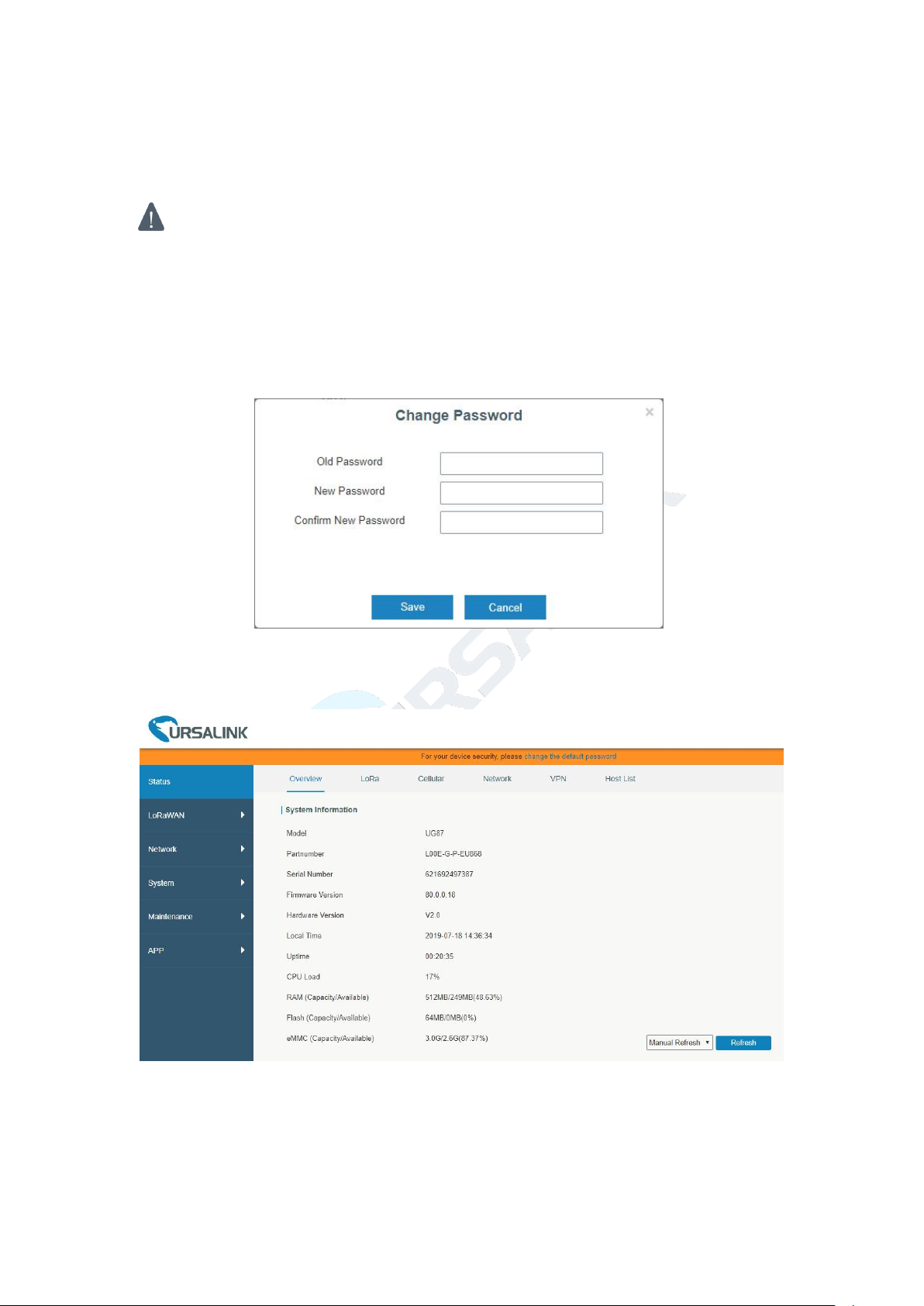
If you enter the username or password incorrectly more than 5 times, the login page
will be locked for 10 minutes.
GUI remotely via the public IP address when remote access is enabled.
3. When you login with the default username and password, you will be asked to modify
the password. It’s suggested that you change the password for the sake of security. Click
"Cancel" button if you want to modify it later.
UG87 User Guide
4. After you login the Web GUI, you can view system information and perform
configuration on the gateway.
14
Chapter 3 Web Configuration
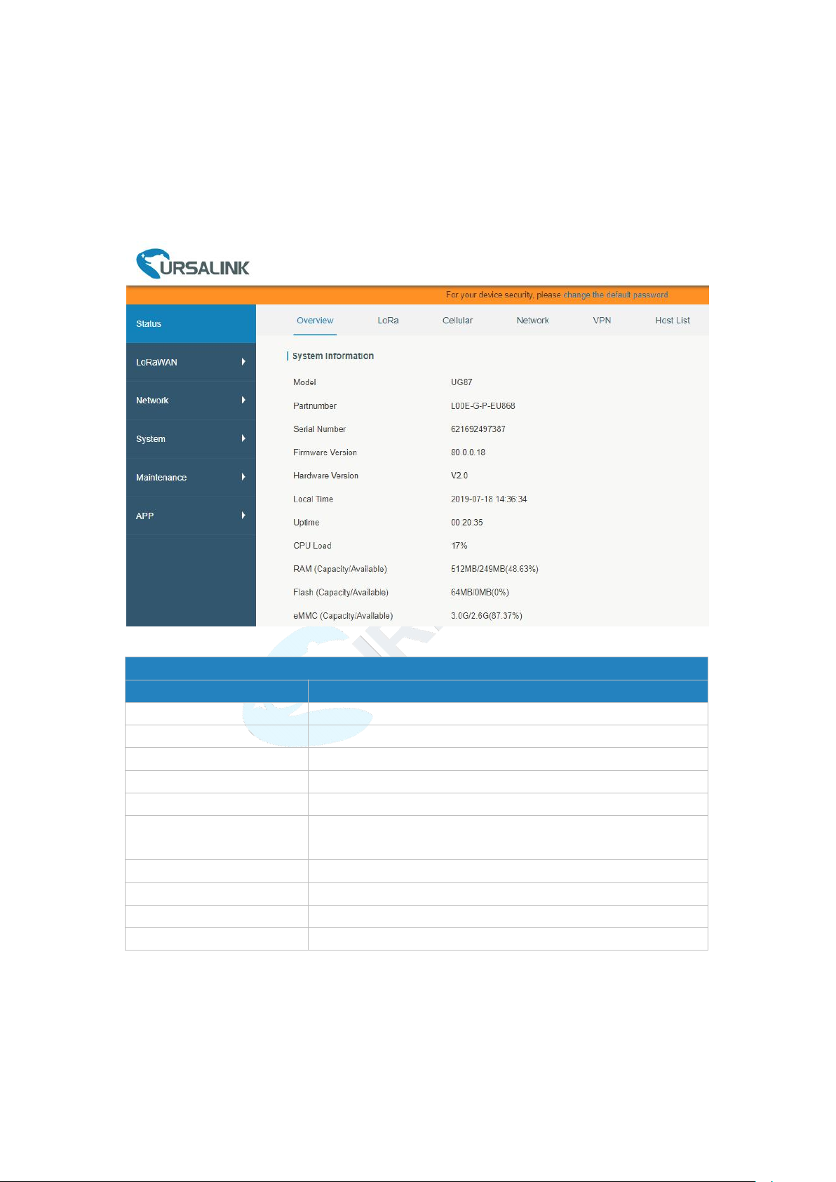
System Information
Item
Description
Model
Show the model name of gateway.
Serial Number
Show the serial number of gateway.
Firmware Version
Show the currently firmware version of gateway.
Hardware Version
Show the currently hardware version of gateway.
Local Time
Show the currently local time of system.
Uptime
Show the information on how long the gateway has been
running.
CPU Load
Show the current CPU utilization of the gateway.
RAM (Capacity/Available)
Show the RAM capacity and the available RAM memory.
Flash (Capacity/Available)
Show the Flash capacity and the available Flash memory.
eMMC (Capacity/Available)
Show the eMMC capacity and the available eMMC memory.
3.1 Status
3.1.1 Overview
You can view the system information of the gateway on this page.
UG87 User Guide
Figure 3-1-1-1
Table 3-1-1-1 System Information
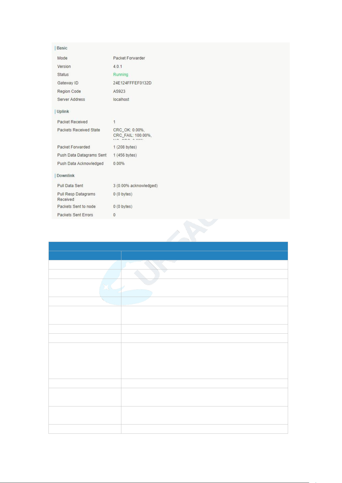
3.1.2 Packet Forwarder
You can view the LoRaWAN status of gateway on this page.
UG87 User Guide
15
Packet Forwarder Status
Item
Description
Mode
Show the working mode of LoRaWAN.
Version
Show the version of packet forwarder software.
Status
Show the status of packet forwarder.
Value include Running, Disabled.
Gateway ID
Show the ID of the gateway.
Region Code
Show the LoRa region code which is based on the gateway’s
variant..
Server Address
Show the IP address of remote LoRaWAN network server.
Packet Received
Show the count of data packet from node to gateway.
Packets received State
Show the RF packets receiving state:
CRC_OK: Percentage of CRC verification
CRC_Fail: Percentage of CRC verification failure
NO_CRC: Percentage of abnormal packets without CRC
Packets forwarded
Packets that CRC verified are sent from gateway to server.
Push Data Datagrams Sent
The total quantity of packets sent from gateway to server,
including the RF packets forwarded and statistics packets.
Push Data Acknowledged
Percentage of acknowledged packets among Push Data
Datagrams Sent.
Pull Data Sent
Show the number of keepalive packets sent to the server, and
Figure 3-1-2-1
16
percentage of acknowledged packet regarding the keepalive
packet from the server.
Pull Resp Datagrams
Received
Show the packet counts and size that will be sent from server to
gateway.
RF Packets Sent to node
Show the RF packet counts and size that will be sent from
gateway to node.
RF Packets Sent Errors
Show the RF packet counts that fail to be sent from server to
node.
Table 3-1-2-1 LoRaWAN Status
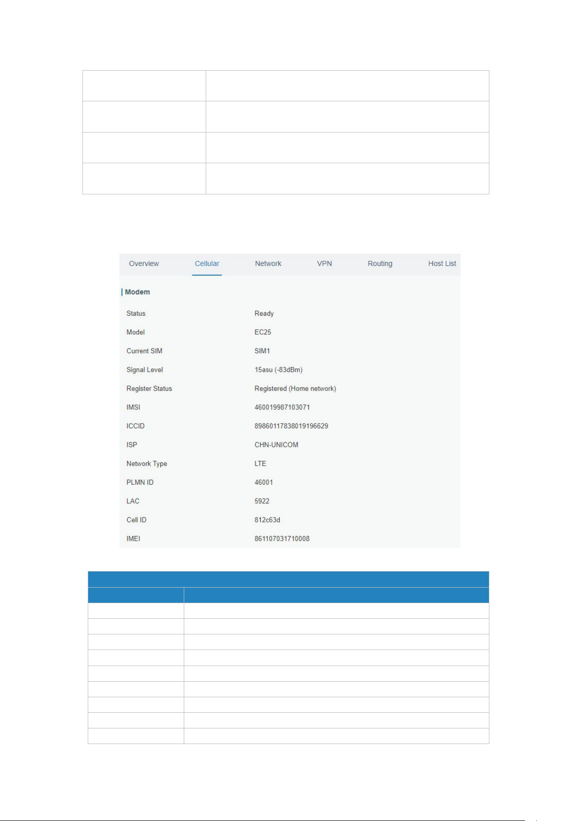
Modem Information
Item
Description
Status
Show corresponding detection status of module and SIM card.
Model
Show the model name of cellular module.
Current SIM
Show the current SIM card used.
Signal Level
Show the cellular signal level.
Register Status
Show the registration status of SIM card.
IMSI
Show IMSI of the SIM card.
ICCID
Show ICCID of the SIM card.
ISP
Show the network provider which the SIM card registers on.
Network Type
Show the connected network type, such as LTE, 3G, etc.
3.1.3 Cellular
You can view the cellular network status of gateway on this page.
UG87 User Guide
Figure 3-1-3-1
UG87 User Guide
17
PLMN ID
Show the current PLMN ID, including MCC, MNC, LAC and Cell ID.
LAC
Show the location area code of the SIM card.
Cell ID
Show the Cell ID of the SIM card location.
IMEI
Show the IMEI of the module.
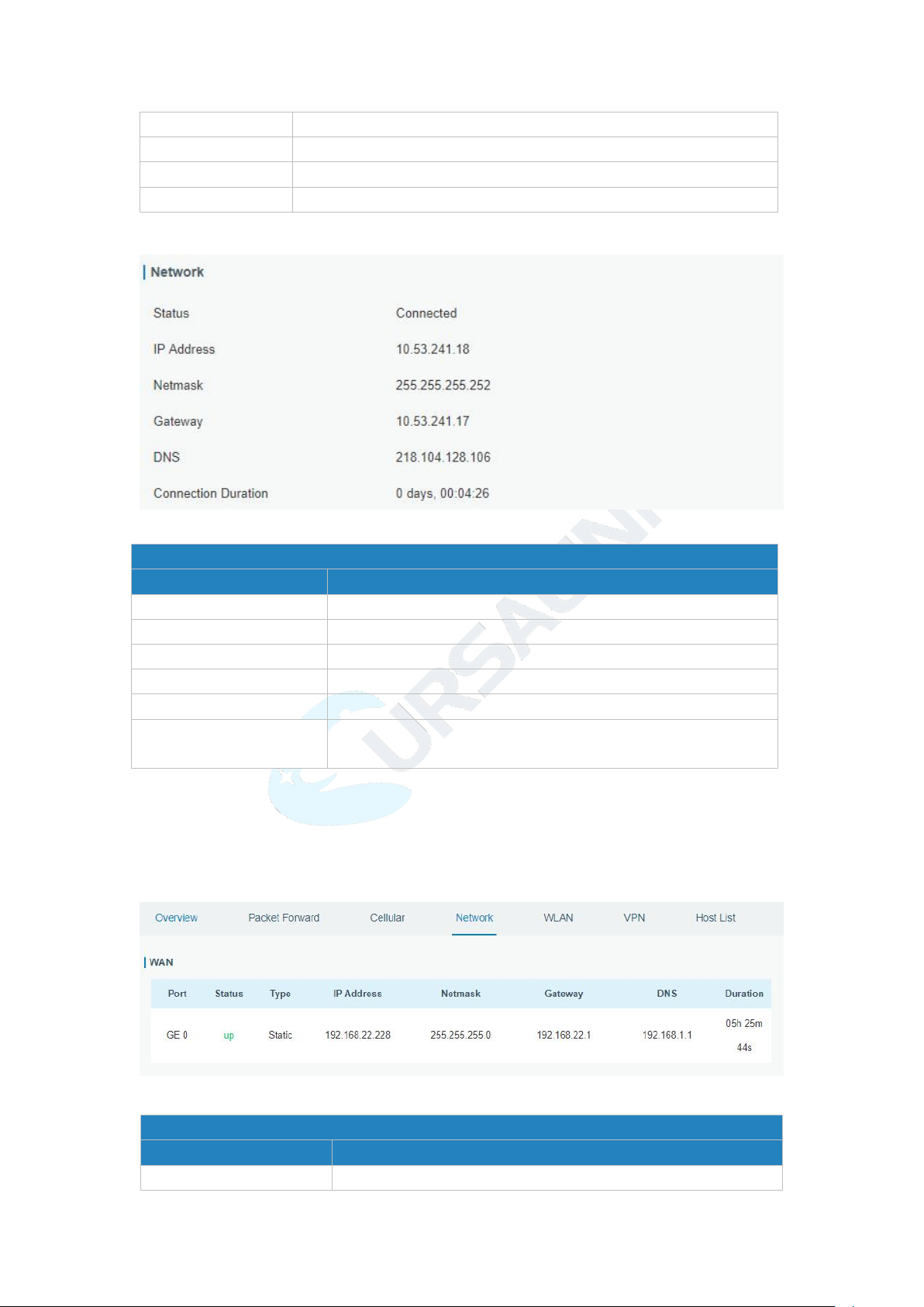
Network Status
Item
Description
Status
Show the connection status of cellular network.
IP Address
Show the IP address of cellular network.
Netmask
Show the netmask of cellular network.
Gateway
Show the gateway of cellular network.
DNS
Show the DNS of cellular network.
Connection Duration
Show information on how long the cellular network has been
connected.
Network
Item
Description
Port
Show the name of WAN port.
Table 3-1-3-1 Modem Information
Figure 3-1-3-2
Table 3-1-3-2 Network Status
3.1.4 Network
On this page you can check the Ethernet port status of the gateway.
Figure 3-1-4-1
UG87 User Guide
18
Status
Show the status of WAN port. "Up" refers to a status that
WAN is enabled and Ethernet cable is connected. "Down"
means Ethernet cable is disconnected or WAN function is
disabled.
Type
Show the dial-up type of WAN port.
IP Address
Show the IP address of WAN port.
Netmask
Show the netmask of WAN port.
Gateway
Show the gateway of WAN port.
DNS
Show the DNS of WAN port.
Duration
Show the information about how long the Ethernet cable has
been connected to WAN port when WAN function is enabled.
Once WAN function is disabled or Ethernet cable is
disconnected, the duration will stop.
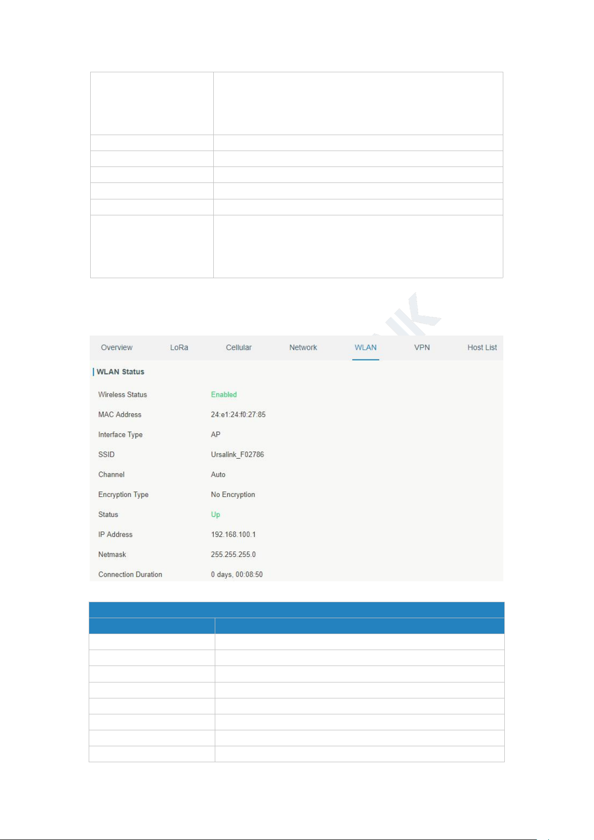
WLAN Status
Item
Description
Wireless Status
Show the wireless status.
MAC Address
Show the MAC address.
Interface Type
Show the interface type, such as "AP" or “Client".
SSID
Show the SSID.
Channel
Show the wireless channel.
Encryption Type
Show the encryption type.
Status
Show the connection status.
IP Address
Show the IP address of the gateway.
Table 3-1-4-1 WAN Status
3.1.5 WLAN (Only Applicable to Wi-Fi Version)
You can check Wi-Fi status on this page, including the information of access point and client.
Figure 3-1-5-1
19
Netmask
Show the wireless MAC address of the gateway.
Gateway
Show the gateway address in wireless network.
Connection Duration
Show information on how long the Wi-Fi network has been
connected.
Table 3-1-5-1 WLAN Status
Associated Stations
Item
Description
IP Address
Show the IP address of access point or client.
MAC Address
Show the MAC address of the access point or client.
Connection Duration
Show information on how long the Wi-Fi network has been
connected.
Figure 3-1-5-2
Table 3-1-5-2 WLAN Status
UG87 User Guide
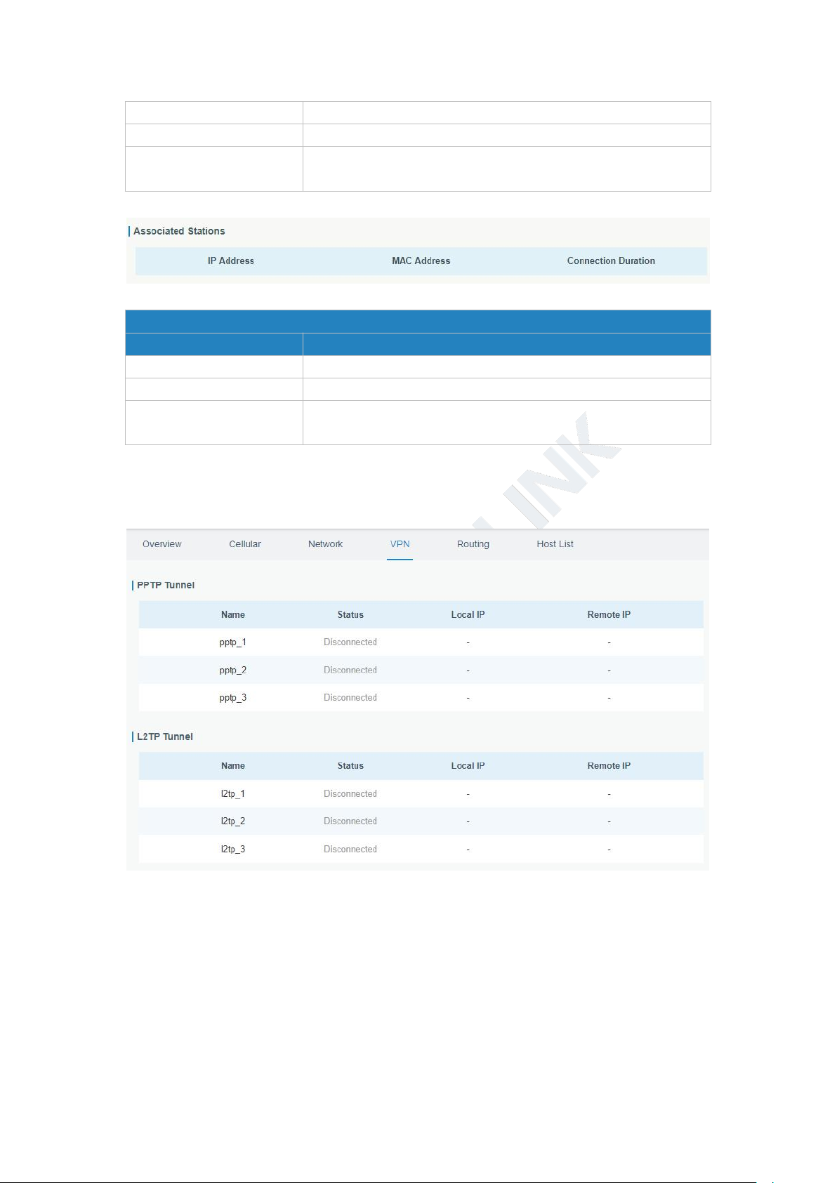
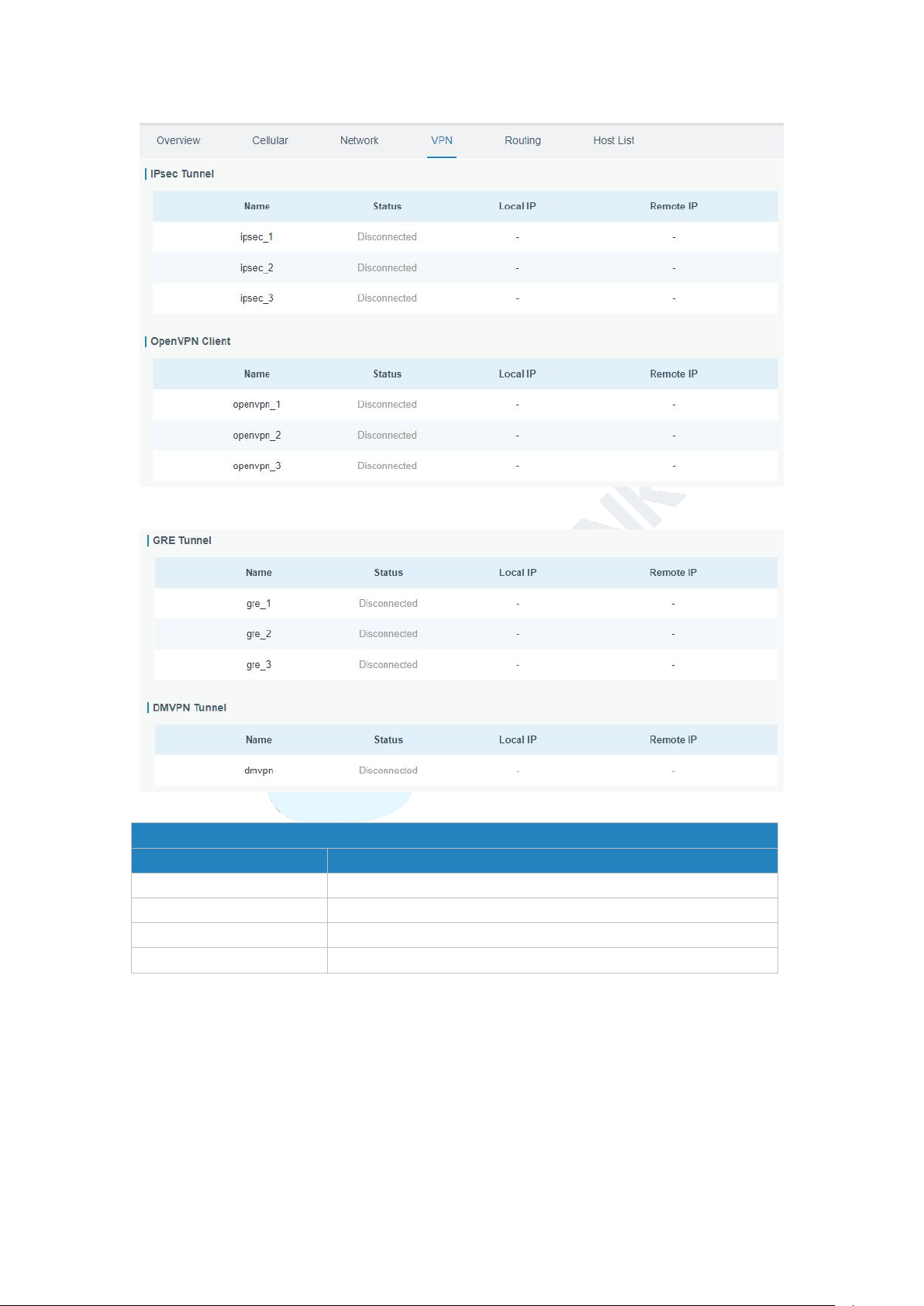
3.1.6 VPN
You can check VPN status on this page, including PPTP, L2TP, IPsec, OpenVPN and DMVPN.
Figure 3-1-6-1
20
Figure 3-1-6-2
VPN Status
Item
Description
Name
Show the name of the VPN tunnel.
Status
Show the status of the VPN tunnel.
Local IP
Show the local tunnel IP of VPN tunnel.
Remote IP
Show the remote tunnel IP of VPN tunnel.
UG87 User Guide
Figure 3-1-6-3
Table 3-1-6-1 VPN Status
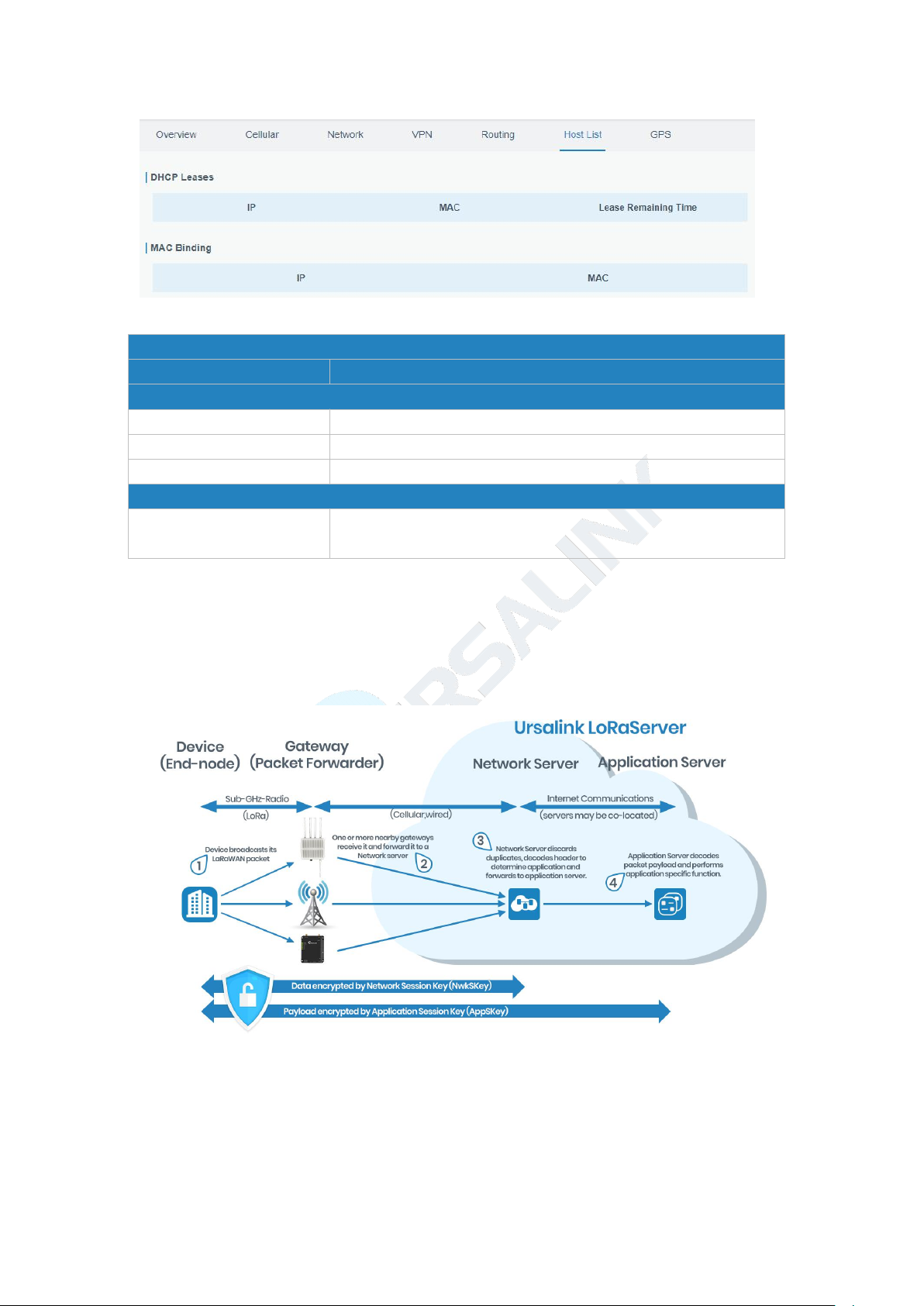
3.1.7 Host List
You can view the host information on this page.
21
Figure 3-1-7-1
Host List
Item
Description
DHCP Leases
IP Address
Show IP address of DHCP client
MAC Address
Show MAC address of DHCP client
Lease Time Remaining
Show the remaining lease time of DHCP client.
MAC Binding
IP & MAC
Show the IP address and MAC address set in the Static IP list of
DHCP service.
UG87 User Guide
3.2 LoRaWAN
Table 3-1-7-1 Host List Description
22
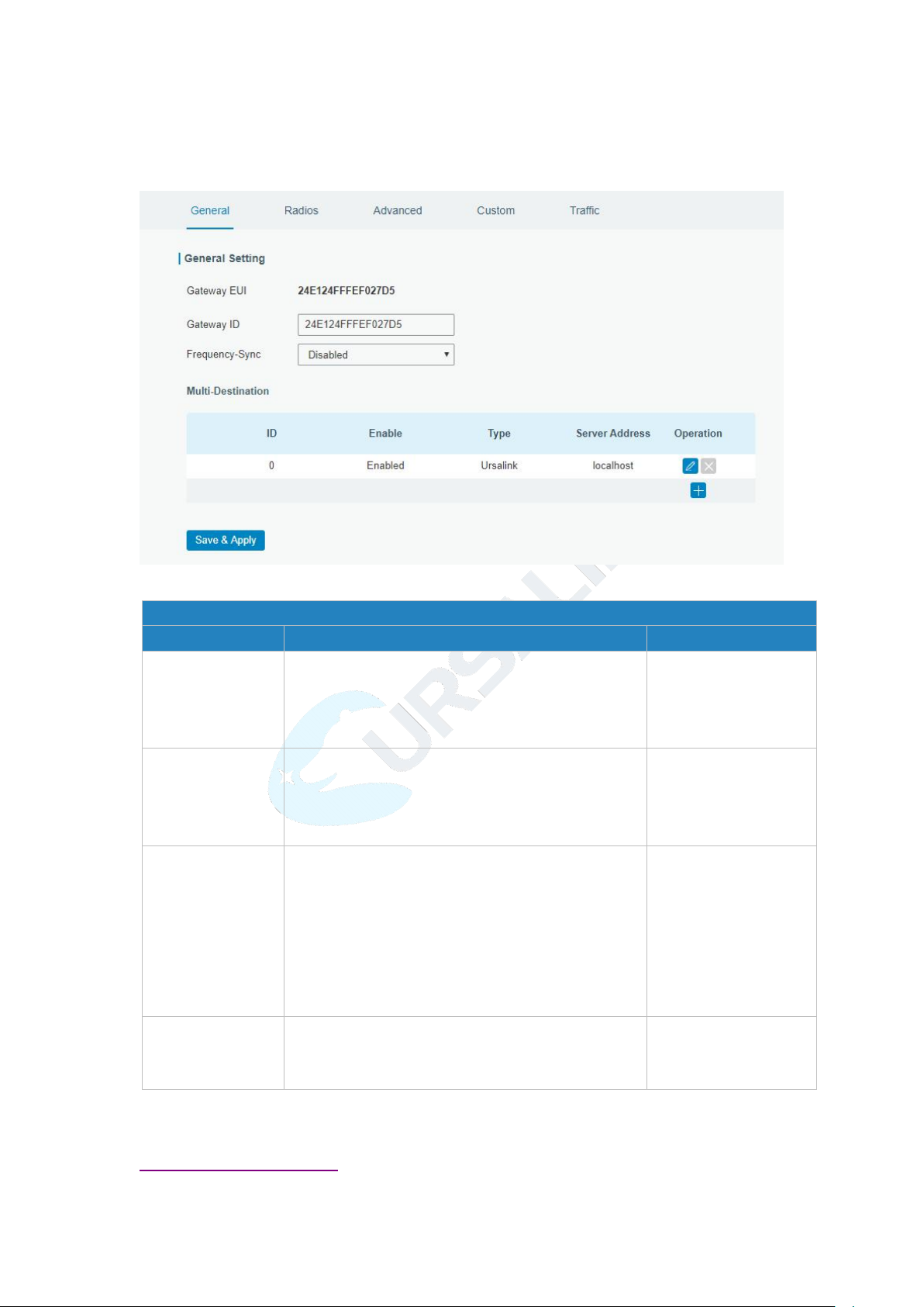
3.2.1 Packet Forwarder
General Settings
Item
Description
Default
Gateway EUI
Show the identifier of the gateway.
Generated from MAC
address of the gateway
and cannot be
changed.
Gateway ID
Fill in the corresponding ID which you’ve used for
register gateway on the remote network server,
such as TTN. It is usually the same as gateway EUI
and can be changed.
The default is the
same as gateway EUI.
Frequency-Sync
Disable: Disable sync frequency configurations
from network server, the gateway will use local
configurations.
Network Server ID: Sync frequency configurations
from network server by selecting the
corresponding ID.
Disable
Multi-Destination
The gateway will forward the data to the network
server address that was created and enabled in
the list.
Local host
3.2.1.1 General
UG87 User Guide
Figure 3-2-1-1
Related Configuration Example
Packet fowarder configuration
Table 3-2-1-1 General Setting Parameters

23
3.2.1.2 Radios
Radios-Radio Channel Setting
Item
Description
Default
Supported
Frequency
Choose the LoRaWAN frequency plan used for
the upstream and downlink frequencies and
datarates. Available channel plans depend on the
gateway’s variant.
The default
frequency is set
based on the
gateway’s variant.
Name
Show the name of central frequency.
Center
Frequency
Enter the central frequency of Radio 0 which
supports transmitting and receiving packet.
Enter the center frequency of Radio 1 which
only supports receiving packet from nodes.
The default is based
on what is specified
in the LoRaWAN
regional parameters
document.
Radios-Multi Channel Setting
Item
Description
Default
Enable
Click to enable this channel to transmit packets.
Enabled
Index
Indicate the ordinal of the list.
Radio
Choose Radio 0 or Radio 1 as center frequency.
Radio 0
Frequency/MHz
Enter the frequency of this channel.
Range: center frequency±
0.9.
The default
frequency is set
based on
the
supported frequency
you have selected.
UG87 User Guide
Figure 3-2-1-2
Table 3-2-1-2 Radio Channels Setting Parameters
Figure 3-2-1-3
Table 3-2-1-3 Multi Channel Setting Parameters
24
Figure 3-2-1-4
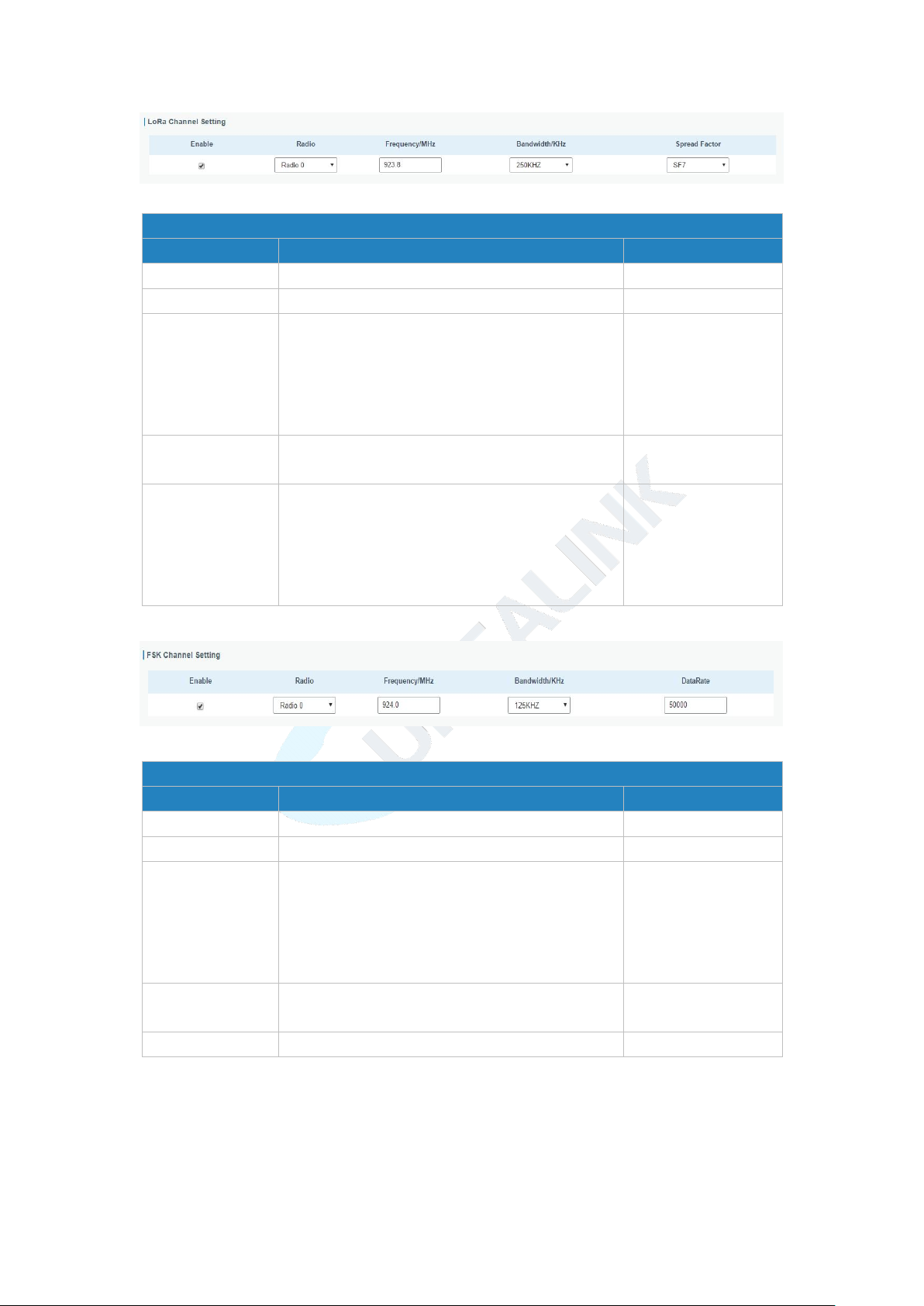
Radios-LoRa Channel Setting
Item
Description
Default
Enable
Click to enable this channel to transmit packets.
Enabled
Radio
Choose Radio 0 or Radio 1 as center frequency.
Radio 0
Frequency/MHz
Enter the frequency of this channel.
Range: center frequency
±
0.9.
The default
frequency is set
based on
the
supported frequency
you have selected.
Bandwidth/MHz
Enter the bandwidth of this channel.
Recommended value: 125KHz, 250KHz, 500KHz
125KHz
Spread Factor
Choose the selectable spreading factor. The
channel with large spreading factor
corresponds to a low rate, while the small one
corresponds to a high rate.
The default is based
on what is specified
in the LoRaWAN
regional parameters
document.
Radios-FSK Channel Setting
Item
Description
Default
Enable
Click to enable this channel to transmit packets.
Disabled
Radio
Choose Radio 0 or Radio 1 as center frequency.
Radio 0
Frequency/MHz
Enter the frequency of this channel.
Range: center frequency±
0.9.
The default
frequency is set
based on
the
supported frequency
you have selected.
Bandwidth/MHz
Enter the bandwidth of this channel.
Recommended value: 125KHz, 250KHz, 500KHz
500KHz
Data Rate
Enter the data rate. Range:500-25000.
500
UG87 User Guide
Table 3-2-1-4 LoRa Channel Setting Parameters
Figure 3-2-1-5
Table 3-2-1-5 FSK Channel Setting Parameters
25
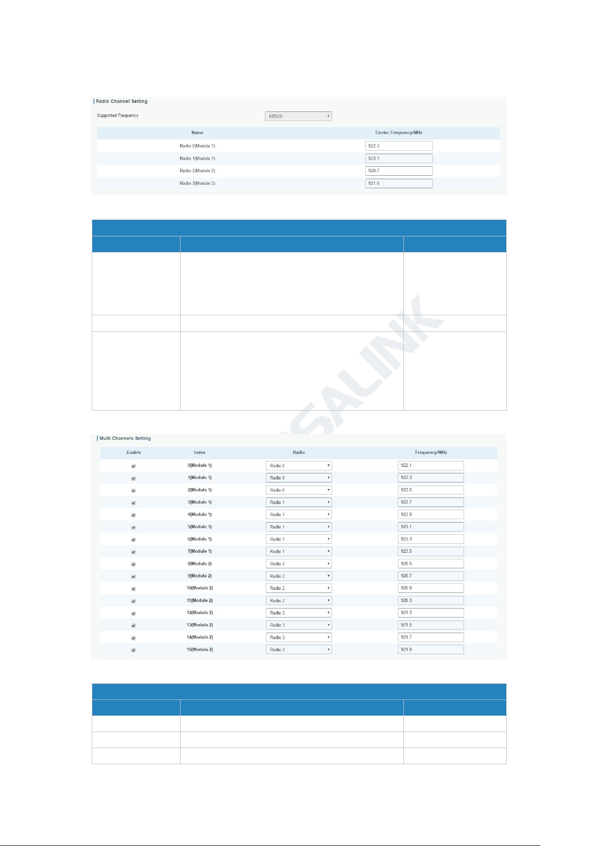
3.2.1.3 Radios (Dual-module)
Radios-Radio Channel Setting (Dual-module)
Item
Description
Default
Supported
Frequency
Choose the LoRaWAN frequency plan used for
the upstream and downlink frequencies and
datarates. Available channel plans depend on the
gateway’s variant.
The default
frequency is set
based on the
gateway’s variant.
Name
Show the name of central frequency.
Center
Frequency
Enter the central frequency of Radio 0 which
supports transmitting and receiving packet.
Enter the center frequency of Radio 1 which
only supports receiving packet from nodes.
The default is based
on what is specified
in the LoRaWAN
regional parameters
document.
Radios-Multi Channel Setting (Dual-module)
Item
Description
Default
Enable
Click to enable this channel to transmit packets.
Enabled
Index
Indicate the ordinal of the list.
Null
Radio
Choose Radio 0, Radio 1, Radio 2 or Radio 3 as
Radio 0
UG87 User Guide
Figure 3-2-1-6
Table 3-2-1-6 Radio Channels Setting Parameters (Dual-module)
Figure 3-2-1-7
26
center frequency.
Frequency/MHz
Enter the frequency of this channel.
Range: center frequency
±
0.9.
The default
frequency is set
based on
the
supported frequency
you have selected.
Table 3-2-1-7 Multi Channel Setting Parameters (Dual-module)
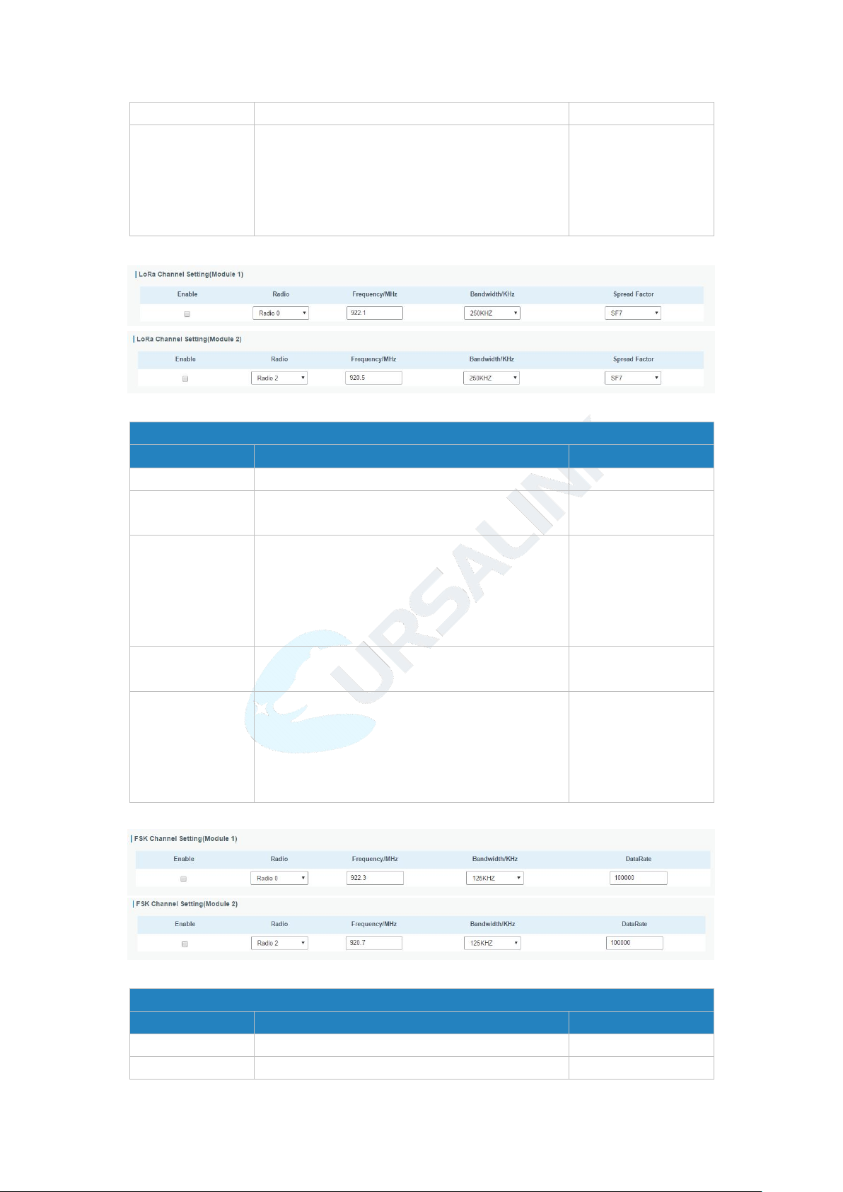
Radios-LoRa Channel Setting
Item
Description
Default
Enable
Click to enable this channel to transmit packets.
Enabled
Radio
Choose Radio 0, Radio 1, Radio 2 or Radio 3 as
center frequency.
Radio 0
Frequency/MHz
Enter the frequency of this channel.
Range: center frequency±
0.9.
The default
frequency is set
based on
the
supported frequency
you have selected.
Bandwidth/MHz
Enter the bandwidth of this channel.
Recommended value: 125KHz, 250KHz, 500KHz
125KHz
Spread Factor
Choose the selectable spreading factor. The
channel with large spreading factor
corresponds to a low rate, while the small one
corresponds to a high rate.
The default is based
on what is specified
in the LoRaWAN
regional parameters
document.
Radios-FSK Channel Setting
Item
Description
Default
Enable
Click to enable this channel to transmit packets.
Disabled
Radio
Choose Radio 0, Radio 1, Radio 2 or Radio 3 as
Radio 0
Figure 3-2-1-8
UG87 User Guide
Table 3-2-1-8 LoRa Channel Setting Parameters
Figure 3-2-1-9
27
center frequency.
Frequency/MHz
Enter the frequency of this channel.
Range: center frequency
±
0.9.
The default
frequency is set
based on
the
supported frequency
you have selected.
Bandwidth/MHz
Enter the bandwidth of this channel.
Recommended value: 125KHz, 250KHz, 500KHz
500KHz
Data Rate
Enter the data rate. Range:500-25000.
500
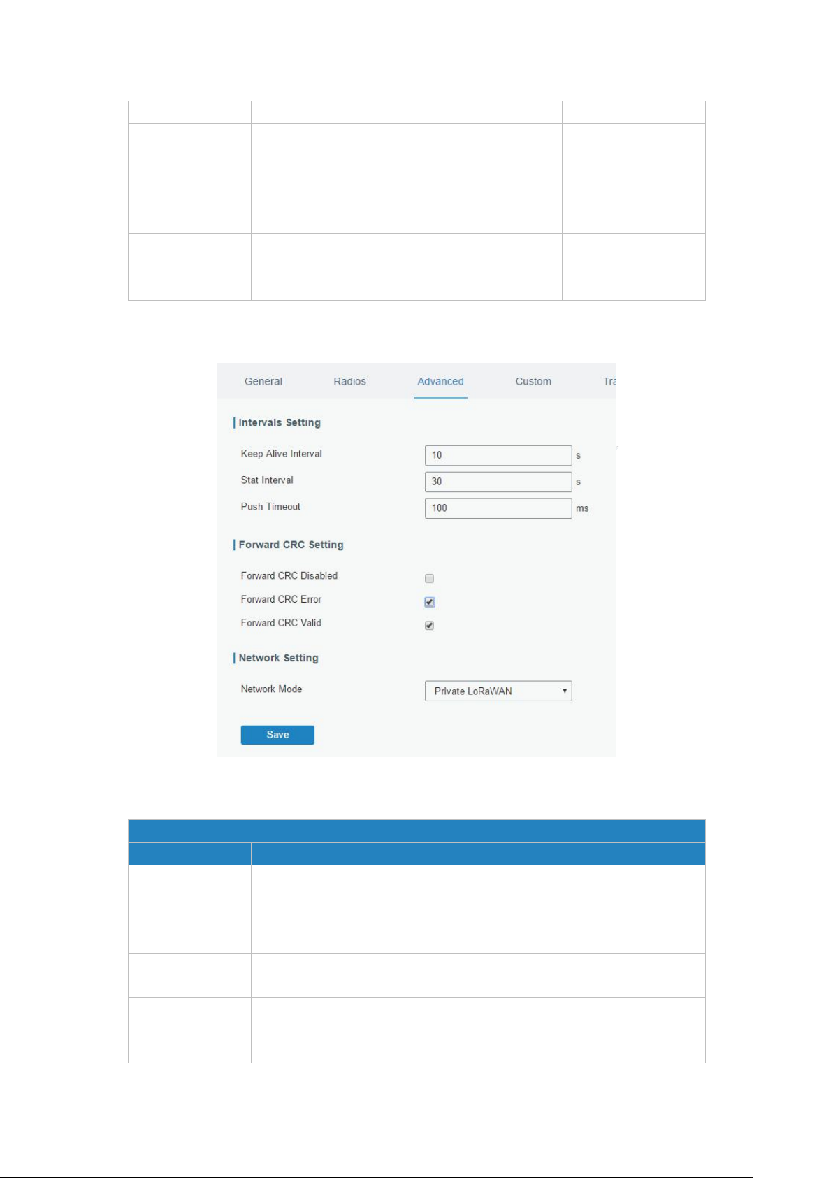
3.2.1.4 Advanced
Advanced
Item
Description
Default
Keep Alive
Interval
Enter the interval of keepalive packet which is sent
from gateway to LoRaWAN network server to keep
the connection stable and alive.
Range: 1-3600.
10
Stat Interval
Enter the interval to update the network server with
gateway statistics. Range: 1-3600.
30
Push Timeout
Enter the timeout to wait for the response from
server after the gateway sends data of node. Rang:
1-3600.
100
UG87 User Guide
Table 3-2-1-9 FSK Channel Setting Parameters
Figure 3-2-1-10
28
Forward CRC
Disabled
Enable to send packets received with CRC disabled to
the network server.
Disabled.
Forward CRC
Error
Enable to send packets received with CRC errors to
the network server.
Disabled.
Forward CRC
Valid
Enable to send packets received with CRC valid to the
network server.
Enabled
Network Mode
select from “Public LoRaWAN”, “Private LoRaWAN”.
Public LoRaWAN: telecom/operator managed
networks, connect multiple applications
(multi-tenant) into a single network.
Private LoRaWAN: individually managed networks,
Network deployed for single application purpose.
Public LoRaWAN
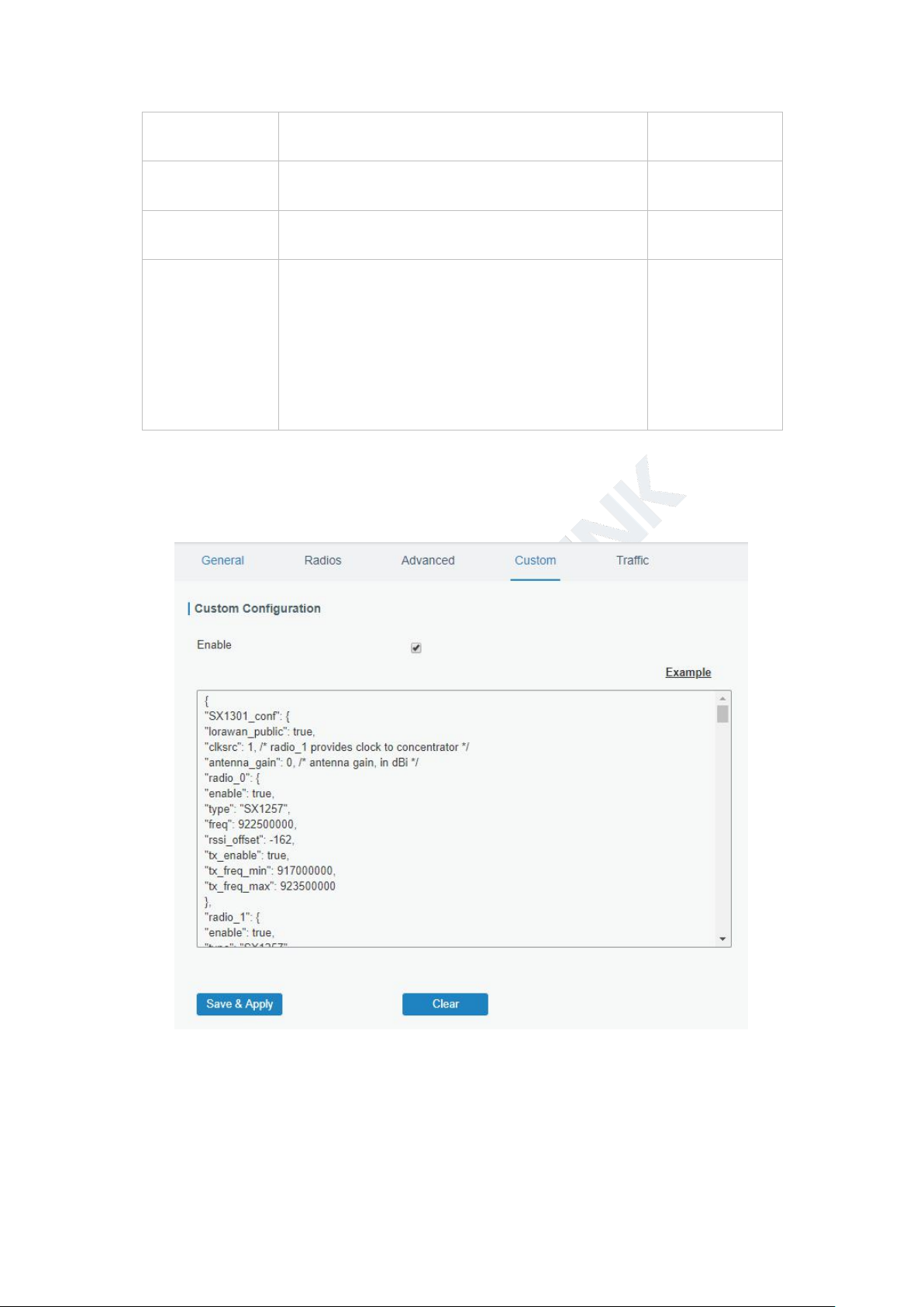
3.2.1.5 Custom
UG87 User Guide
Table 3-2-1-10 Advanced Parameters
When Custom Configuration mode is enabled, you can write your own packet forwarder
configuration file in the edit box to configure packet forwarder. Click “Save” to save your custom
configuration file content, and click “Apply” to take effect. You can click “Clear” to erase all
content in the edit box. If you don’t know how to write configuration file, please click “Example”
to go to reference page.
Figure 3-2-1-11

UG87 User Guide
29
Item
Description
Refresh
Click to obtain the latest data.
Clear
Click to clear all data.
Rfch
Show the channel of this packet.
Direction
Show the direction of this packet.
Time
Show the receiving time of this packet.
Ticks
Show the ticks of this packet.
Frequency
Show the frequency of the channel.
Datarate
Show the datarate of the channel.
Coderate
Show the coderate of this packet.
RSSI
Show the received signal strength.
SNR
Show the signal to noise ratio of this packet
.
3.2.1.6 Traffic
When navigating to the traffic page, any recent traffic received by the gateway will display. To
watch live traffic, click Start.
Figure 3-2-1-12
Table 3-2-1-11 Traffic Parameters
30
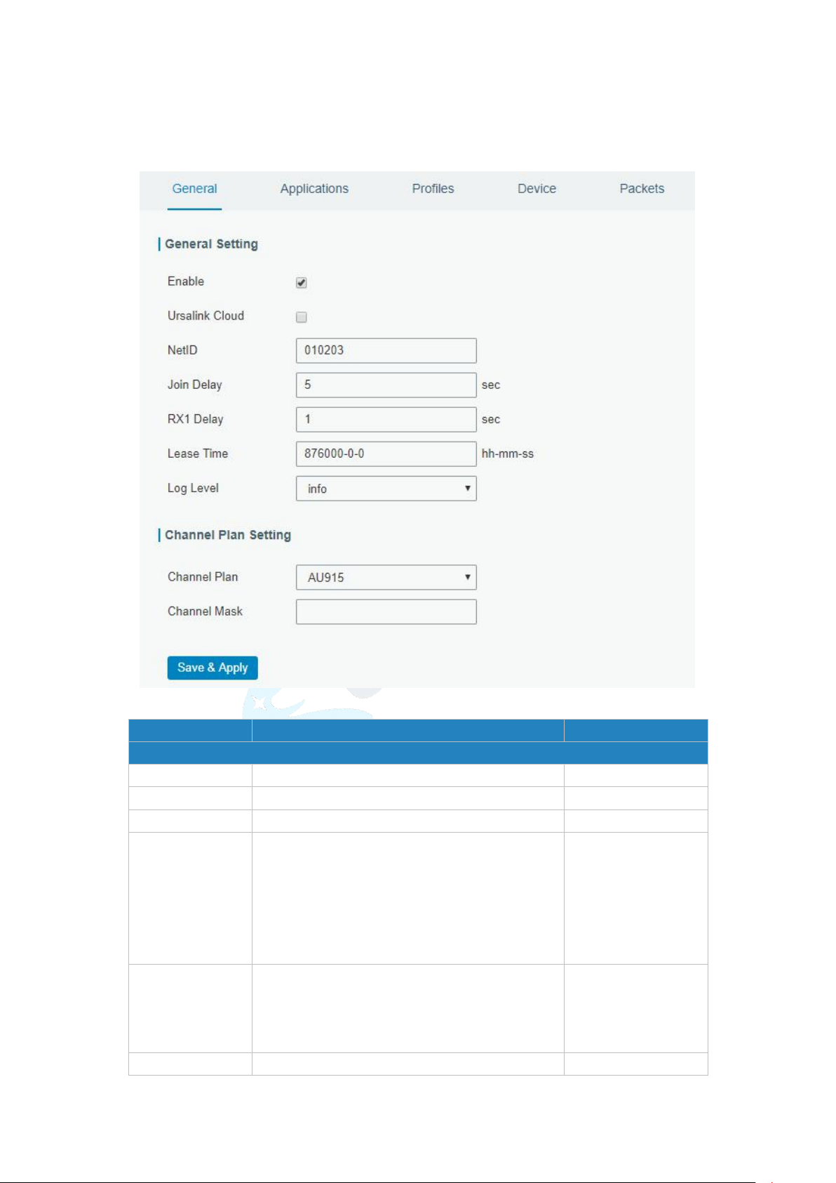
3.2.2 Network Server
Item
Description
Default
General Setting
Enable
Click to enable Network Server mode.
Enable
Ursalink Cloud
Enabled to connect gateway to Ursalink Cloud.
Disable
NetID
Enter the network identifier.
01023
Join Delay
Enter the interval time between when the
end-device sends a Join_request_message to
network server and when the end-device
prepares to open RX1 to receive the
Join_accept_message sent from network
server.
5
RX1 Delay
Enter the interval time between when the
end-device sends uplink packets and when the
end-device prepares to open RX1 to receive
the downlink packet.
1
Lease Time
Enter the amount of time till a successful join
"744-00-00"
3.2.2.1 General
UG87 User Guide
Figure 3-2-2-1
 Loading...