

Ursalink UG85 Quick Start Manual
1
UG85 LoRaWAN Gateway
Ursalink Technology Co., Ltd.
Quick Start Guide
1
Welcome
Document
Description
Ursalink UG85 Datasheet
Datasheet for the Ursalink UG85 LoRaWAN Gateway.
Ursalink UG85 User Guide
Users can refer to the guide for instruction on how to log in the
web GUI, and how to configure all the settings.
Thank you for choosing Ursalink UG85 LoRaWAN Gateway.
This guide teaches you how to install the UG85 and how to log in the web GUI to configure the device. Once
you complete the installation, refer to the Ursalink UG85 User Guide for instructions on how to perform
configurations on the device.
Related Documents
This Quick Start Guide only explains the installation of Ursalink UG85 LoRaWAN Gateway. For more
functionality and advanced settings, please refer to the relevant documents as below.
The related documents are available on Ursalink website: http://www.ursalink.com.
Declaration of Conformity
UG85 is in conformity with the essential requirements and other relevant provisions of the CE, FCC, and
RoHS.
For assistance, please contact
Ursalink technical support:
Email: support@ursalink.com
Tel: 86-592-5023060
Fax: 86-592-5023065
www.ursalink.com

Ursalink UG85 Quick Start Guide
2
1 × UG85
1 × Ethernet Cable
1 × Power Adapter
1 × Stubby LoRa
Antenna
1 × GPS Antenna
(Optional)
1 × Magnetic Cellular
Antenna (Optional)
1 × Stubby Wi-Fi
Antenna (Optional)
1 × Stubby Cellular
Antenna(Optional)
If any of the above items is missing or damaged, please contact your Ursalink sales
representative.
1 × 6-Pin Pluggable
Terminal
1 × DIN Rail Kit
4 × Setscrews
1 × Warranty Card
1. Packing List
Before you begin to install the UG85 LoRaWAN Gateway, please check the package contents to verify that
you have received the items below.
1.1 Package Contents
Note: If UG85 support cellular function, magnetic cellular antenna is default choice.
www.ursalink.com
3
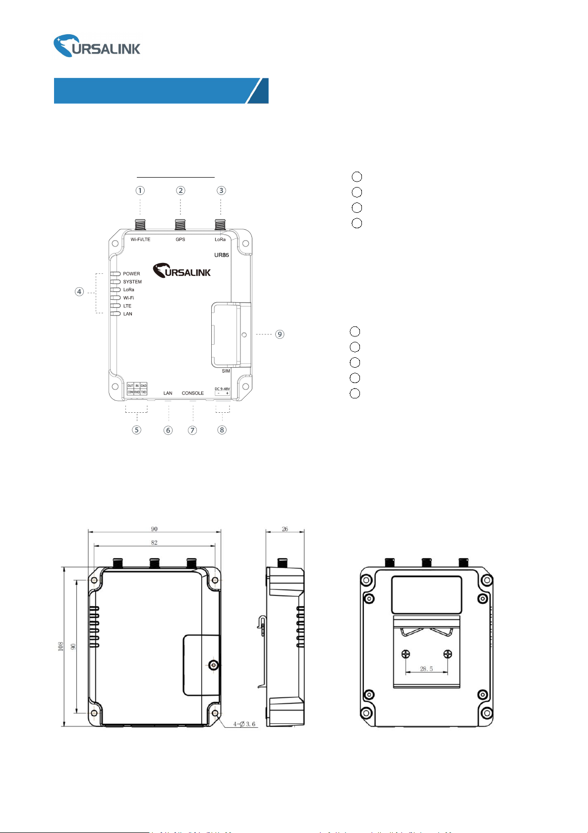
2.1 Overview
2. Hardware Introduction
1
WIFI/LTE Antenna
2
GPS Antenna
3
LoRa Antenna
4
LED Indicator Area
POWER: Power Indicator
SYSTEM: Status Indicator
LORA:LoRa Indicator
WIFI: WIFI Indicator
LTE: Cellular Status Indicator
LAN: Ethernet Port Status Indicator
5
Serial Port & I/O
6
Ethernet WAN/LAN Port
7
Console Port
8
Power Connector
9
SIM and Reset Button Holder
A. Front Panel
Ursalink UG85 Quick Start Guide
UG85 Front Panel
2.2 Dimensions (mm)
www.ursalink.com

4
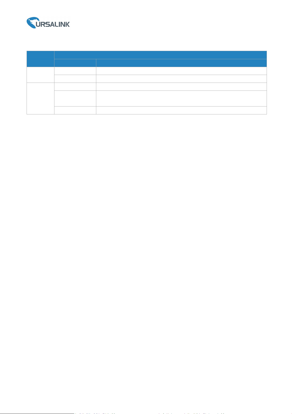
2.3 Pinouts
LED
Indication
Status
Description
POWER
Power Status
On
The power is switched on
Off
The power is switched off
SYSTEM
System Status
Green Light
Static: Start-up
Blinking slowly: the system is running
properly
Red Light
The system goes wrong
LoRa
LoRa Status
Green Light
Packet Forwarder mode is running well.
Off
Packet Forwarder mode is running off.
WIFI
WIFI Status
Green Light
WIFI is connected
Off
WIFI is disconnected
LTE
Cellular Status
Off
SIM1 or SIM2 is registering or fails to register
(or there are no SIM cards inserted)
Green Light
Blinking slowly: SIM1 or SIM2 has been
registered and is ready for dial-up
Blinking rapidly: SIM1 or SIM2 has been
registered and is dialing up now
Static: SIM1 or SIM2 has been registered and
dialed up successfully
LAN
Ethernet
Port Status
Off
Disconnected
Green Light
Blinking: Transmitting data
Static: Connected
PIN
RS232
DIDODescription
1
---
---
OUT
Digital Output
2
---IN---
Digital Input
3
GND
---
---
Ground
4
---
COM
COM
Common Ground
5
RXD
---
---
Receive Data
6
TXD
---
---
Transmit Data
PIN
Description
11
Positive
12
Negative
Ursalink UG85 Quick Start Guide
2.4 LED Indicators
www.ursalink.com
5
2.5 Reset Button
Function
Description
SYSTEM LED
Action
Reboot
Blinking
Press and hold the reset button for about 5-15 seconds.
Static Green
Release the button and wait for system to reboot.
Reset
Blinking
Press and hold the reset button for more than 15 seconds.
Static Green →
Rapidly Blinking
Release the button and wait.
Off → Blinking
The gateway is now reset to factory default.
Ursalink UG85 Quick Start Guide
www.ursalink.com
Ursalink UG85 Quick Start Guide
6
3. Hardware Installation
Environmental Requirements
- Power Input: 9-48 VDC
- Power Consumption: Typical 3.3W (Max 6.4 W)
- Operating Temperature: -40°C to 70°C (-40°F -158°F)
- Relative Humidity: 0% to 95% (non-condensing) at 25°C/77°F
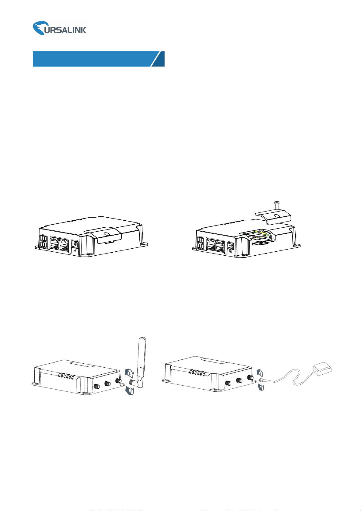
3.1 SIM Card Installation
A. Unscrew the cover of the SIM card then B. Put SIM card into the slot and screw it up.
take it off.
3.2 Antenna Installation
Rotate the antenna into the antenna connector accordingly.
The external antenna should be installed vertically always on a site with a good cellular signal.
www.ursalink.com
 Loading...