

Ursalink UC11 Series Quick Start Manual
1
UC11 Series
LoRa Remote I/O
Quick Start Guide
1
Welcome
Document
Description
Ursalink UC11 Datasheet
Datasheet for the Ursalink UC11 series remote LoRa I/O.
Ursalink UC11 User Guide
Users could refer to the guide for instruction on how to configure
all the settings.
Thank you for choosing Ursalink UC11 series remote LoRa I/O.
This guide describes how to install the UC11 series remote LoRa I/O and how to connect to Ursalink
LoRaWAN gateway. Once you complete the installation, refer to the Ursalink UC11 User Manual for
instructions on how to perform configurations on the device.
Related Documents
This Start Guide only explains the installation of Ursalink UC11 series remote LoRa I/O. For more
functionality and advanced settings, please refer to the relevant documents as below.
The related documents are available on Ursalink website: http://www.ursalink.com.
Declaration of Conformity
Ursalink UC11 series remote LoRa I/O is in conformity with the essential requirements and other relevant
provisions of the CE, FCC, and RoHS.
For assistance, please contact
Ursalink technical support:
Email: support@ursalink.com
Tel: 86-592-5023060
Fax: 86-592-5023065
www.ursalink.com
Ursalink UC11 Quick Start Guide
2
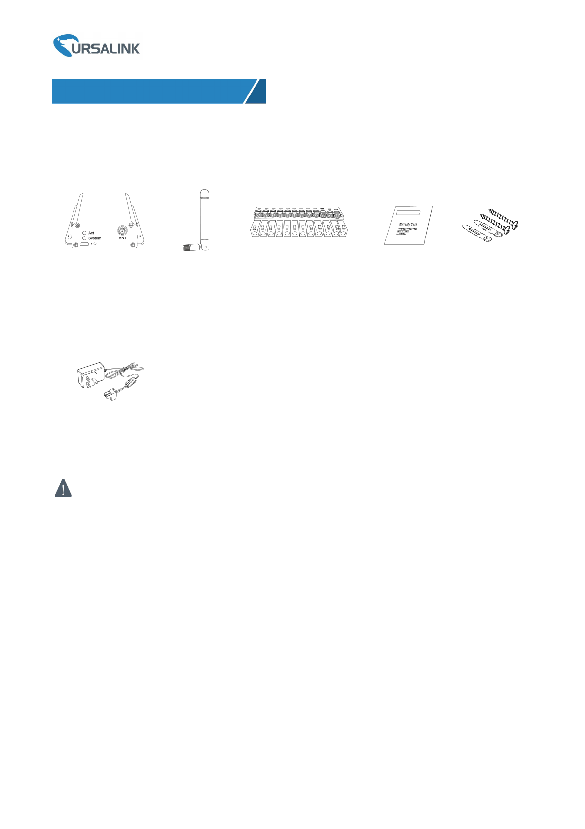
1 × UC11
1 × Stubby LoRa
Antenna
1 × 12-Pin Pluggable
Terminal
1 × Warranty Card
Setscrews
If any of the above items is missing or damaged, please contact your Ursalink sales
Representative.
1 × Power Adapter
(Optional)
1. Packing List
Before you begin to install the UC11 series remote LoRa I/O, please check the package contents to verify
that you have received the items below.
1.1 Package Contents
Optional Accessories
www.ursalink.com
3
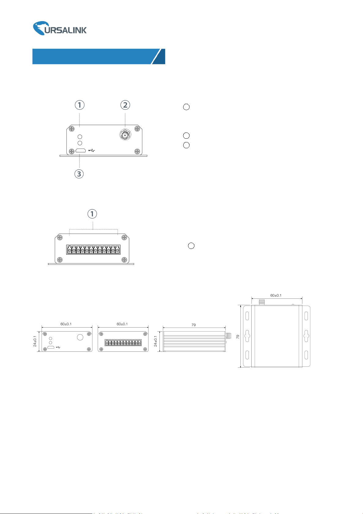
2.1 Overview
2. Hardware Introduction
1
LED Indicator Area
System: System Indicator
ACT: Network Indicator
2
LoRa Antenna Connector
3
Micro USB Interface
1
12-Pin Pluggable Terminal
A. Front Panel
B. Rear Panel
Ursalink UC11 Quick Start Guide
2.2 Dimensions (mm)
www.ursalink.com
4
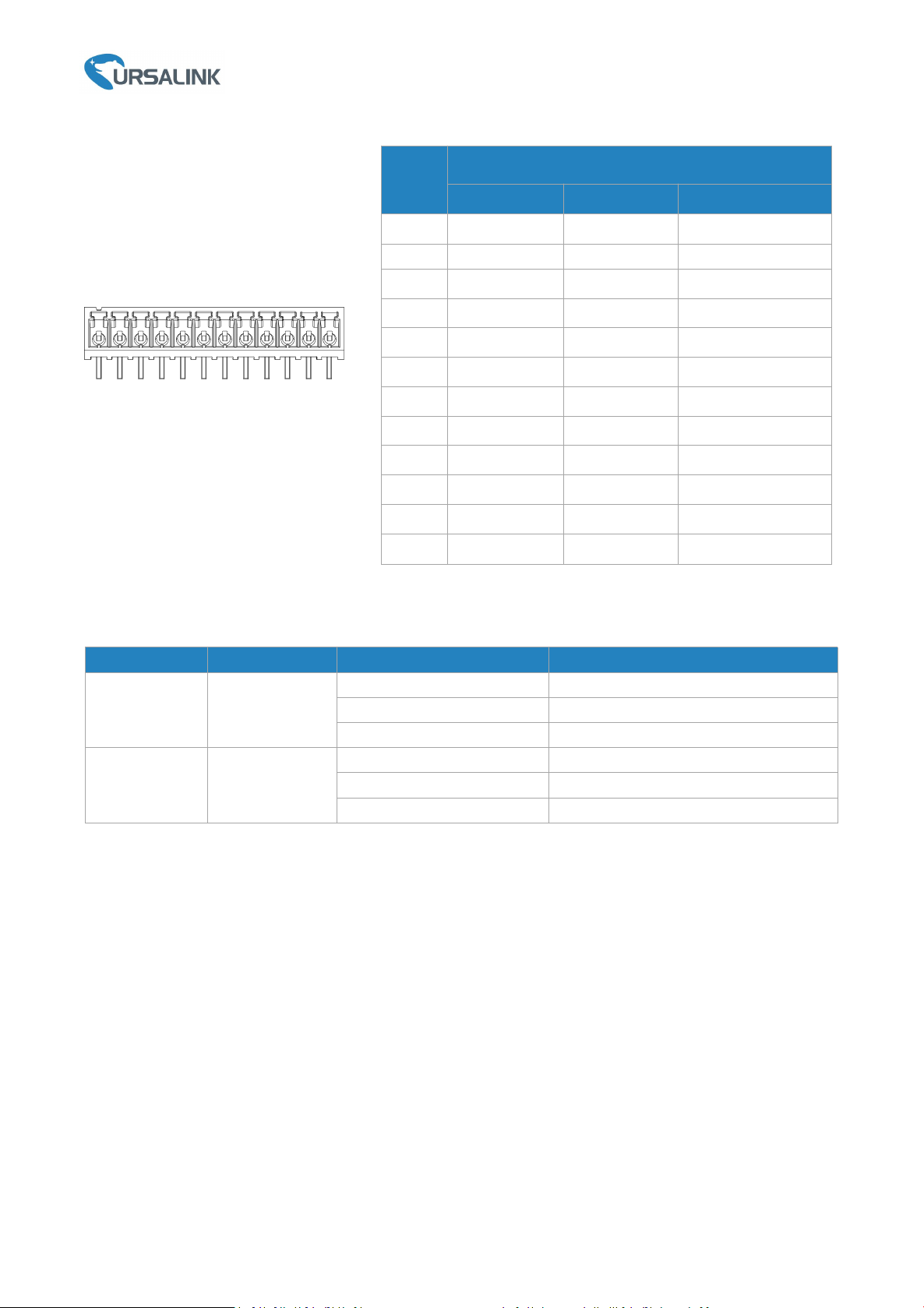
2.3 Pinouts
LED
Indication
Status
Description
System
System Status
Solid On
System booting
On for 500ms, off for 500ms
Working properly
On for 100ms, off for 100ms
Failed to send data
ACT
Network Status
Off
Failed to join network
On for 75ms, off for 3000ms
Join the network successfully
On for 500ms, off for 500ms
Sending/Receiveing data
PIN
Models
UC1114
UC1122
UC1152
1
GND
GND
GND
2
VIN
VIN
VIN
3
IN1NCRXD
4
IN1_COM
AIN1+
TXD
5
IN2
AIN1-
GND
6
IN2_COM
AIN2+
A
7
OUT1_COM
AIN2-
B
8
OUT1_NCININ
9
OUT1_NO
IN_COM
IN_COM
10
OUT2_COM
OUT_COM
OUT_COM
11
OUT2_NC
OUT_NC
OUT_NC
12
OUT2_NO
OUT_NO
OUT_NO
Ursalink UC11 Quick Start Guide
2.4 LED Indicators
www.ursalink.com
 Loading...