

Ursalink UC1114 User Manual

2
Contents
UC1114 User Guide
1. Preface
2. Introduction
3. Installation
4. Configuration
5. Application Examples
.............................................................................................................................................
....................................................................................................................................
2.1 Features
2.2 Parameters
2.3 LED Indicator Description
3.1 Environment
3.2 Power Supply
3.3 Micro USB Port
3.4 Terminal Description
3.5 Digital Input
3.6 Relay Output
4.1 Configuration via PC
4.1.1 Serial Port Settings
4.2 Status
4.3 LoRaWAN
4.3.1 Basic
4.3.2 Channel
4.3.3 Advanced
4.4 Command
4.4.1 Read Command from Device
4.4.2 Open a Command File
4.4.3 Save the Command to Device
4.4.4 Save the Command as File
4.5 IF-THEN Behaviour Command
4.5.1 Supported IF Condition
4.5.2 Supported THEN Actions
4.6 Upgrade
5.1 Periodic Status Report
5.2 Monitoring Alarm
5.3 Control an Appliance
5.3.1 Control a Bulb by Sending a Message
5.3.2 Send an Alert When Over-temperature Occurs
5.3.3 Turn on the Heater Regularly
.................................................................................................................................
............................................................................................................................
......................................................................................................................................
..........................................................................................................................
.........................................................................................................................
......................................................................................................................
...........................................................................................................................
..........................................................................................................................
..................................................................................................................................
...................................................................................................................................
.............................................................................................................................
..........................................................................................................................
.....................................................................................................................
..................................................................................................................
............................................................................................................................
...............................................................................................................................
...................................................................................................................
................................................................................................................
......................................................................................................
.............................................................................................................
..............................................................................................................
.....................................................................................................
...................................................................................
..............................................................................................
..................................................................................
.......................................................................................
.............................................................................................
............................................................................................
..........................................................................................
.........................................................................................................
...........................................................................................................
......................................................................
......................................................
...................................................................................
3
3
3
4
4
4
4
5
5
6
6
7
7
7
8
10
11
11
13
14
16
16
16
16
16
17
17
19
20
21
21
21
22
22
23
23

UC1114 User Guide
3
1. Preface
Thank you for choosing Ursalink UC1114 LoRa Remote I/O. This user guide will present in detail
all the functions and features of the product. The UC1114 is designed for both industrial and
commercial applications and helps devices stay connected. The product should be used under
the guidance of this user guide, referring to parameters and technical specifications. The UC1114
is a compact, high-performance device that offers LoRaWAN connectivity for remote access and
easy management of machines and equipment over the cellular network.
We bear no liability for property loss or physically injury arising from abnormal or incorrect usage
of this product.
2. Introduction
Ursalink UC1114 is designed as a cost-effective industrial machine monitoring device that
monitors and controls up to 2 dry contacts and 2 drivable relay outputs.
With the aid of Ursalink UC1114, the alarm condition brings attention to engineering personnel
immediately. The output can be connected with an alarm indication device, such as a light or
horn.
The device can give immediate response to the status of both the input and output conditions. A
LoRa module is embedded in the Ursalink UC1114.
This user guide is intended to provide detailed technical specifications and explanations to
basic users as well as the technically-minded groups. It is a live document, and will be updated
from time to time. Please ensure that you have the latest version, by checking our website at:
https://www.ursalink.com/en/documents-download/
2.1 Features
2 digital inputs, connected with up to 2 dry contact devices
2 relay drivable outputs
Reliable performance with built-in watchdog
Customizable conditions, programmable actions
Send uplink alert messages according to user-defined conditions
Automatic switching of field devices at set times
Sendand receive messages via LoRaWAN technology
Comply with the LoRaWAN Class C protocol
Support star network and mesh network
High Rx sensitivity and adjustable Tx power

4
2.2 Parameters
Parameter Item
Reference Scope
Antenna
50 Ω SMA Antenna Interface
Frequency Band
EU 433, CN 470-510, EU 863-870, US 902-928, AU
915-928, KR 920-923
Sensitivity
-147 dBm @300bps
Output Power
20dBm
Protocol
LoRaWAN Class C
Digital Input
Opto-isolated depending on voltage
Can accept any DC signals of any type, including:
➢
DC Voltage (3-24 V)
Digital Output
2 x SPDT Relay Contact Rating:
3Amp DC (Max: 30 V) or 3Amp AC (Max: 250 V)
IO Connector type
Screw Terminals
DC Power Supply
5-24 VDC
Operating
Temperature
-40°C to +70°C (-40°F to +158°F)
Relative Humidity
0% to 95% (non- condensing)
Dimensions
79 x 60 x 24 mm
UC1114 User Guide
2.3 LED Indicator Description
System:
Solid On: System booting
On for 500ms, off for 500ms: Working properly
On for 100ms, off for 100ms: Failed to send data
ACT:
Off: Failed to join network
On for 75ms, off for 3000ms: Joined the network successfully
On for 500ms, off for 500ms: Sending/Receiving data
3. Installation
3.1 Environment
Due to the product properties of the Ursalink UC1114, we STRONGLY advise that it should not be
installed in proximity to a variable speed drive or with any other electrically noisy equipment. DO
NOT install the Ursalink UC1114 into a metal enclosure unless an antenna is mounted on the
outside of the enclosure.
UC1114 User Guide
5
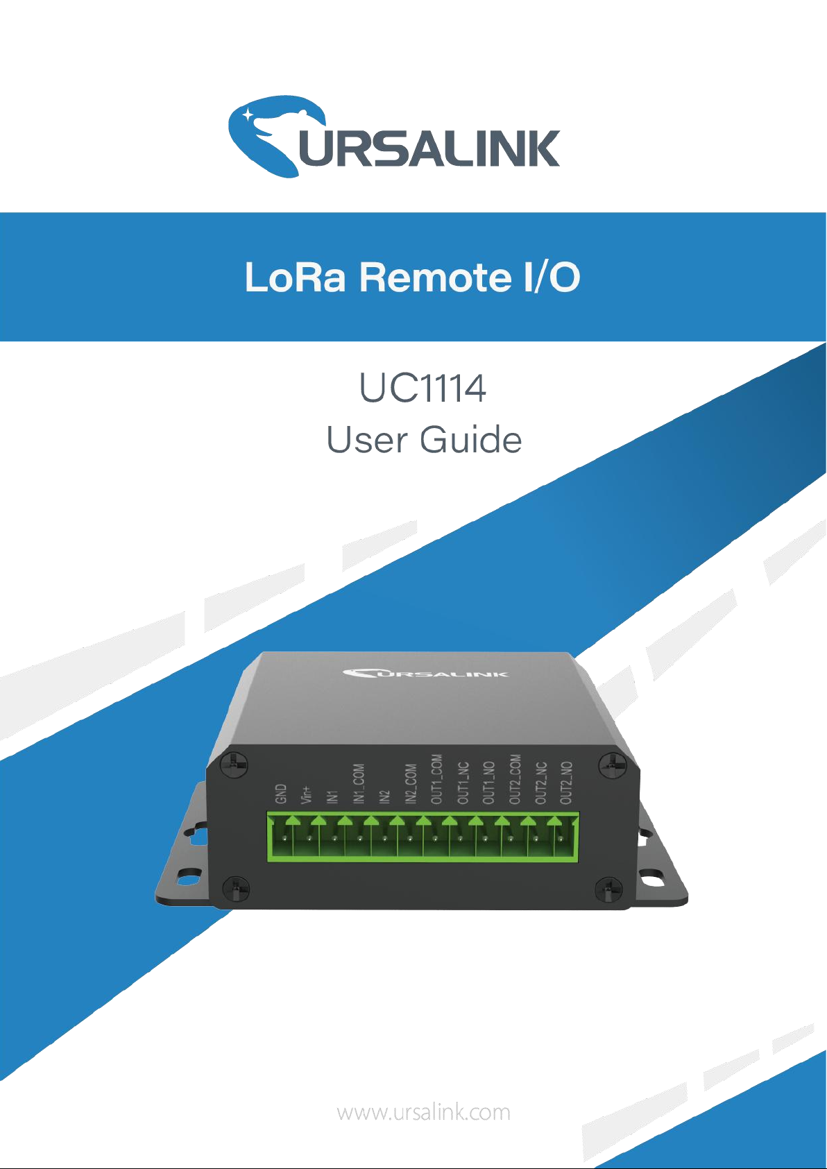
3.2 Power Supply
The Ursalink UC1114 has a terminal block interface where a power supply can be connected. The
power supply should have the following specifications:
Output Voltage: 12V nominal
Output Current: 0.5A
Installation:
A suitable power supply comes with the product.
For industrial applications, it is advised that the Ursalink UC1114 should be installed into its own
metal housing and be powered from a separate power supply (as opposed to sharing one with
other equipment) .
Please Note: While the Ursalink UC1114 has fairly rugged internal power supply circuitry, no
special provision for lightning protection is well in place. If the Ursalink UC1114 is used in an area
where thunderstorm is about to occur, it is advisable to use a commercially available lightning
suppressor (the same applies to inputs or outputs connected to wires longer than 2 or 3 meters).
The guarantee does not cover damage resulting from lightning strikes! The Ursalink UC1114 can
operate reliably from voltages in the range of 5 to 24 VDC.
3.3 Micro USB Port
The Ursalink UC1114 provides a micro USB port to connect to a PC via USB cable, which allows
the PC to configure the unit.
6
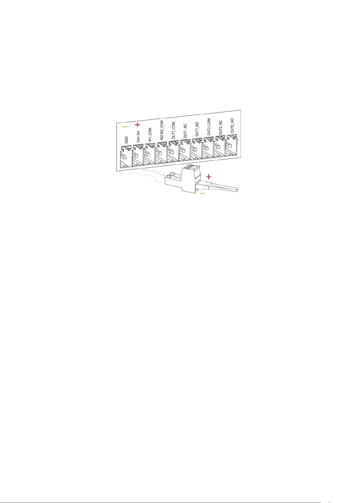
3.4 Terminal Description
Terminal
Description
Vin+
Positive terminal of the DC power supply (+)
GND
Negative terminal of the DC power supply (-)
1 [DC 5-24V]
2 [Digital Input]
Opto-isolated depending on voltage DC Voltage (3-24V)
3 [Digital Output]
Driving relay to connect NC or NO
UC1114 User Guide
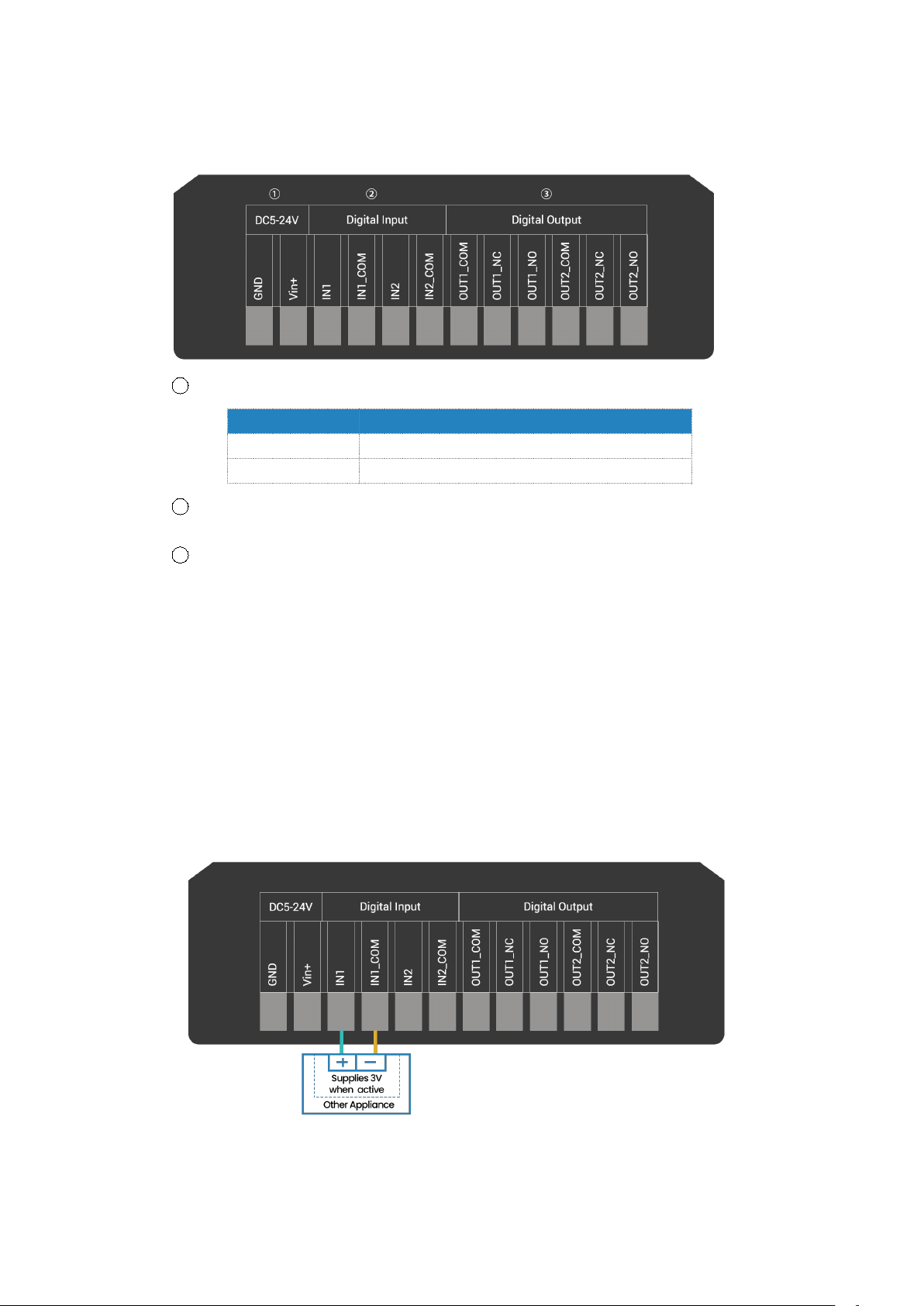
3.5 Digital Input
When the input is triggered either as high or low, the Ursalink UC1114 will take action if you
have pre-configured related command.
Terminal "IN1" or "IN2" is internally pulled high. Leaving the connection open or connecting
it to "0 - 1 V", which will indicate an "Input-De-activate" state.
When terminal "IN1" or "IN2" is connected to "3-24V", it will indicate an "Input-Activate"
state.
Trigger voltage: Minimum = 3 VDC, Maximum = 24 VDC.
UC1114 User Guide
7
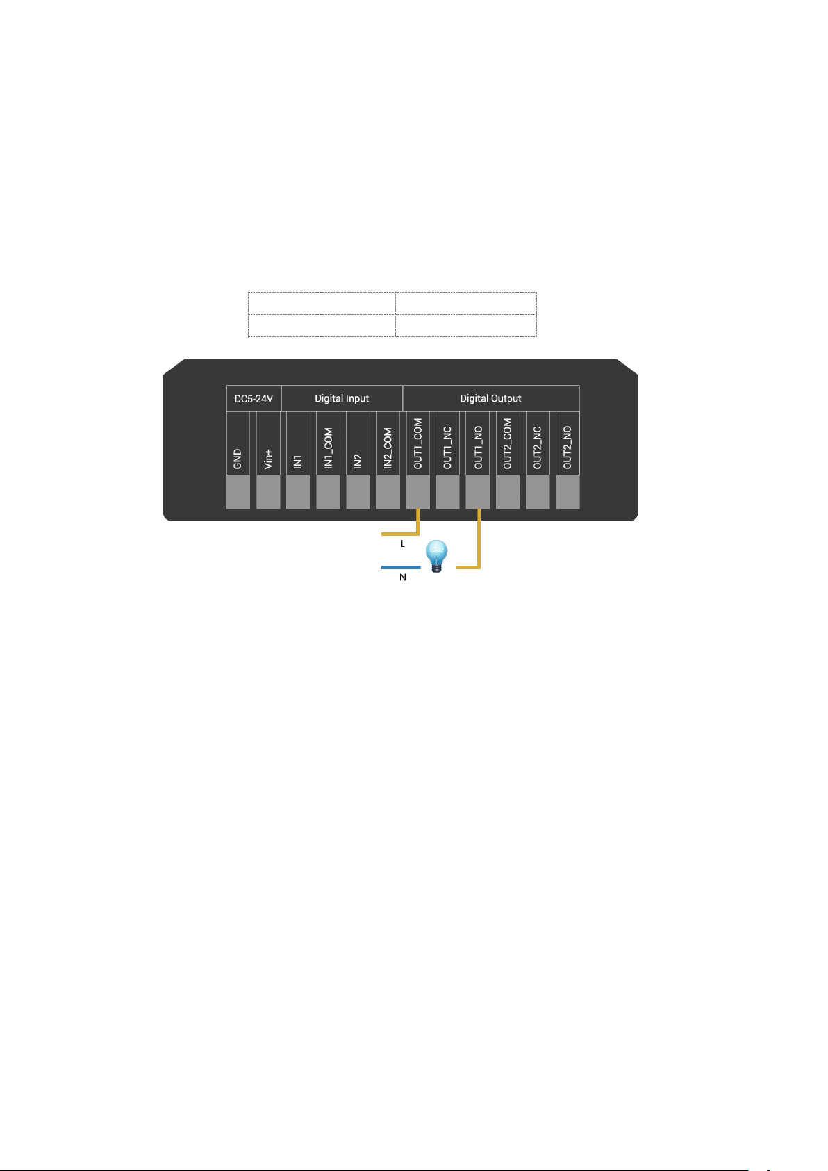
Maximum Current
3 Amp
Maximum Voltage
250VAC, 30 VDC
3.6 Relay Output
The output is used for switch circuits ON & OFF and can be controlled by command message
The output terminals are internally connected to a 3 Amp SPDT relay
OUT_NC = Normally Closed
OUT_COM = Common
OUT_NO = Normally Open
4. Configuration
4.1 Configuration via PC
Follow these steps:
Step 1:
Connect the Ursalink UC1114 to PC via the micro USB port.
Step 2:
Power on the Ursalink UC1114.
Step 3:
Run the Ursalink ToolBox.
UC1114 User Guide
8
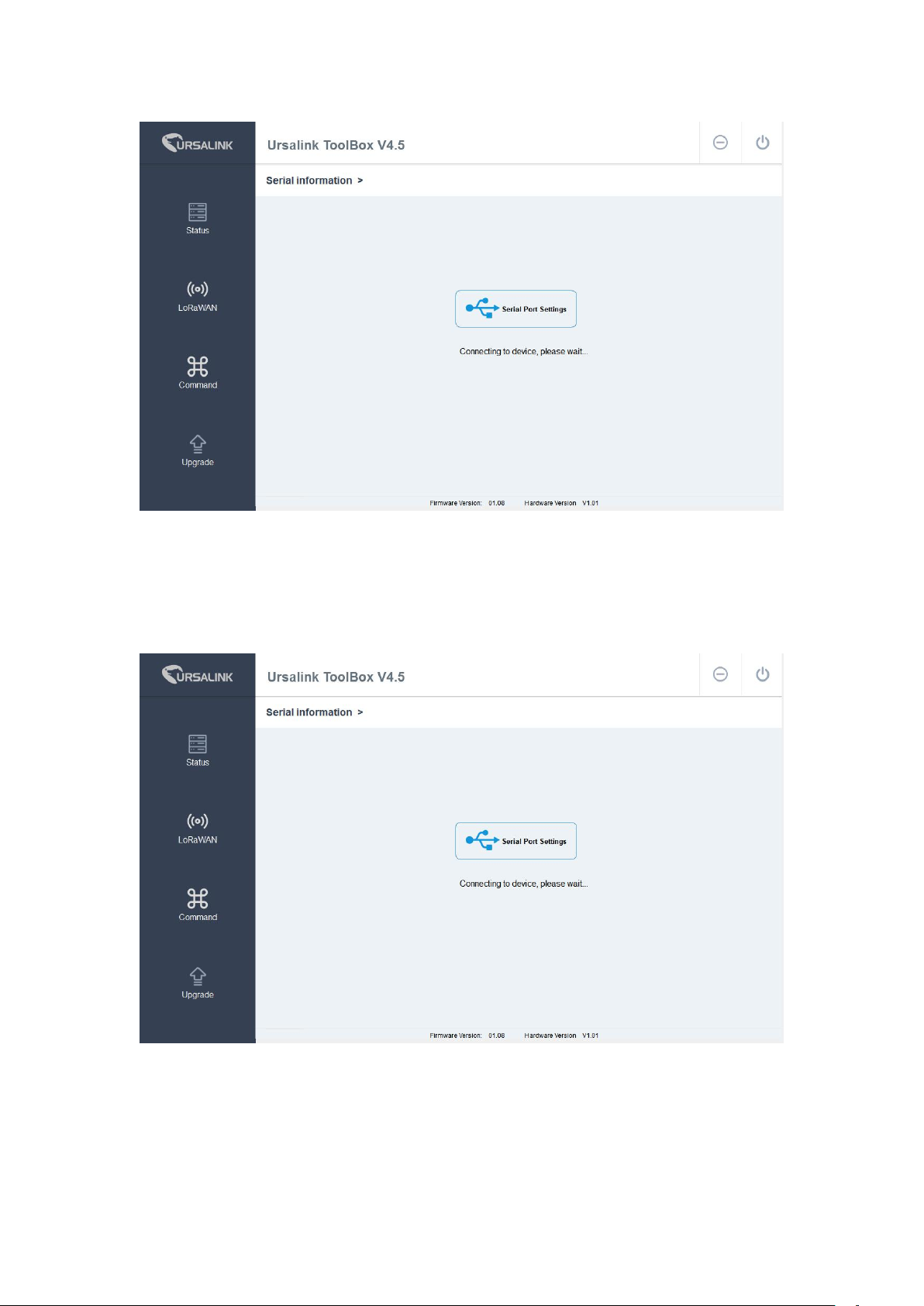
The software will show this interface when getting started. Here you can create a new setup,
import an existing setup from your PC, or retrieve the current setup from the Ursalink UC1114.
4.1.1 Serial Port Settings
When the Ursalink ToolBox displays: Connecting to device, please wait...
You can click Serial Port Settings to set the correct serial port parameters.
 Loading...