

Page 1
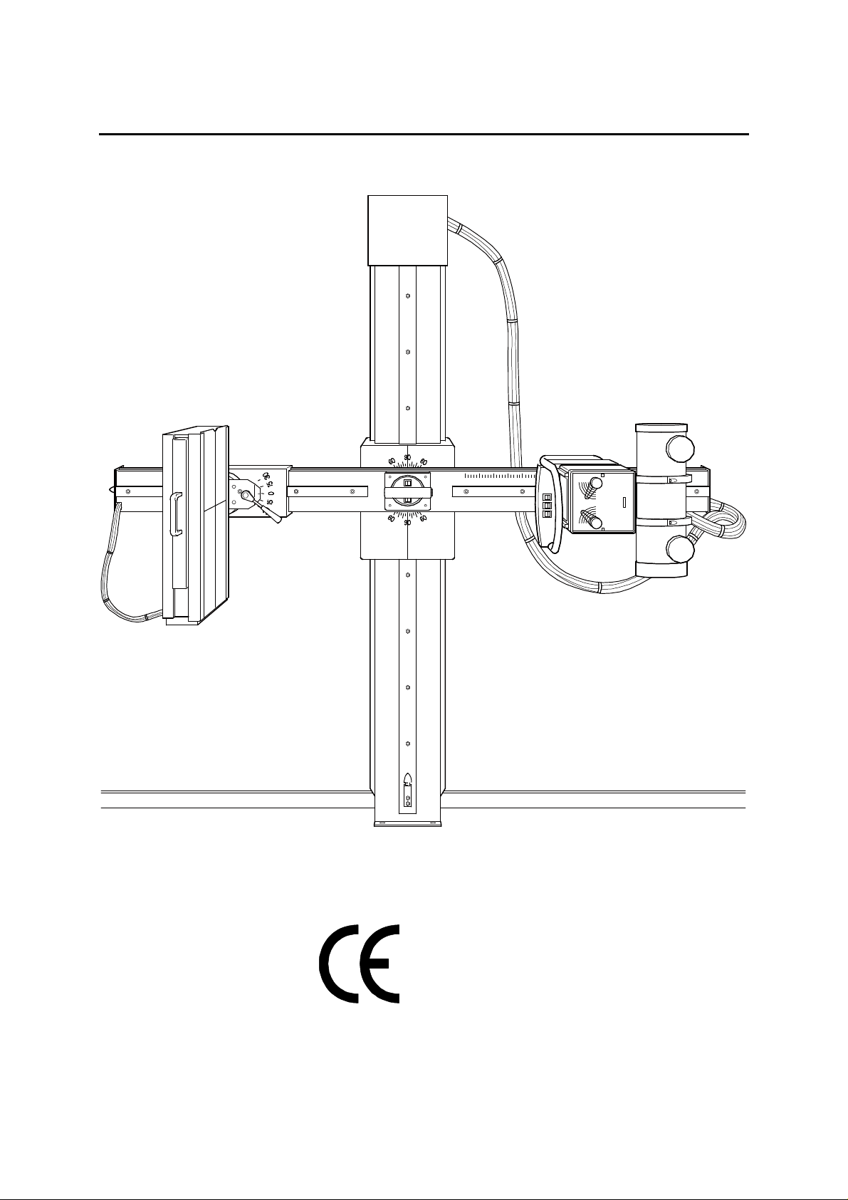
MOUNTING INSTRUCTIONS COSMOS-2
0125
________________________________________________________________________
English Edition
07/99 -1 of 34- 0380 7224
Rev. 06 © 1999 Hans Pausch Röntgengerätebau Graf-Zeppelin-Str. 1 D-91056 Erlangen ALL RIGHTS RESERVED Ru
Page 2

TABLE OF CONTENTS Page
1. Specification
1.1 General Safety Notes 3
1.2. Weight of Components 3
1.3. Dimensions of Components 3
1.4 Shipping Weight and Dimensions 3
1.5 Component Designation 4
1.6. Dimensional Drawings 5
1.7 Power Connection 6
1.8 Special Tools Required 6
1.9. Schematics 7
1.10 Wiring Diagram 8
1.11 Physical Location of Electrical Components 9
1.12 Component Numbers and Designation 9
1.13 Component check list 10
2. Mounting of Unit
2.1 Site Preparation 11
2.2 Uncrating 11
2.3 Unit preparation 12
2.4 Unit mounting 12
2.5 Leveling the unit 13
2.5.1 Loading of counter weights 14
2.6 Mounting of Bucky Support 14
2.7 Mounting of Controls 14
2.8 Mounting of X-Ray Tube and Collimator 14
2.9 Mounting of Bucky 15
2.10 Release the vertical drive 15
2.11 Electrical Connections 16
3. Adjustments
3.1 Bucky Tilt Adjustment 17
3.2 Adjustment of Rotation 17
3.3 Adjustment of Vertical Movement 17
3.4 Adjustment of Rotational Lock 18
3.5 Vertical Lock 18
3.6 SID-Pointer 18
3.7 SID-Drive Clutch 19
3.8 SID End Switch 19
4.0 Technical Maintenance
4.1 Mechanical and Electrical Checks 21
4.2 Functional Checks 25
4.3 Spare Parts 26
4.4 Spare Parts List 28
4.5 Name Plate Location 32
4.6 Maintenance documentation 33
0380 7224 - 2 of 34 - 07/99
Rev. 06 © 1999 Hans Pausch Röntgengerätebau Graf-Zeppelin-Str. 1 D-91056 Erlangen ALL RIGHTS RESERVED Ru
Page 3

1. Specifications
1.1. General Safety Notes
In the Federal Republic of Germany, the electrical installation of rooms used for medical
purposes must conform to the provisions of VDE Standard 0107. Consult installation layout plan. During installation it is important that all protective ground wire connections
provided by the manufacturer properly made before the equipment is started up. The protective ground wires between the individual system components and the power supply
are connected as shown in the wiring diagram. Regulations of professional associations
concerning safety and accident prevention must be observed. No work may be performed
on parts carrying a voltage higher than 42V (Peak Voltage). If it is necessary to turn on the
power for execution of movements of the equipment in the mode of installation procedure,
it must be shut down immediately after completion of these movements.
1.2 Weight of Components
Basic unit (column with swivel arm) approx. 190kg
Counterweight carriage with weight plates approx. 200kg
Bucky support, cover plate and accessories approx. 25kg
1.3 Dimensions
Basic unit 920 x 330 x 2125 mm
Counter weight carriage 200 x 240 x 900 mm
Bucky support 100 x 640 x 580 mm
Cover plate 30 x 610 x 640 mm
1.4 Shipping Weight and Dimensions
Basic unit 1110 x 560 x 2340 mm approx. 325 kg
Counter weight 360 x 320 x 1150 mm approx. 230 kg
07/99 -3 of 34- 0380 7224
Rev. 06 © 1999 Hans Pausch Röntgengerätebau Graf-Zeppelin-Str. 1 D-91056 Erlangen ALL RIGHTS RESERVED Ru
Page 4
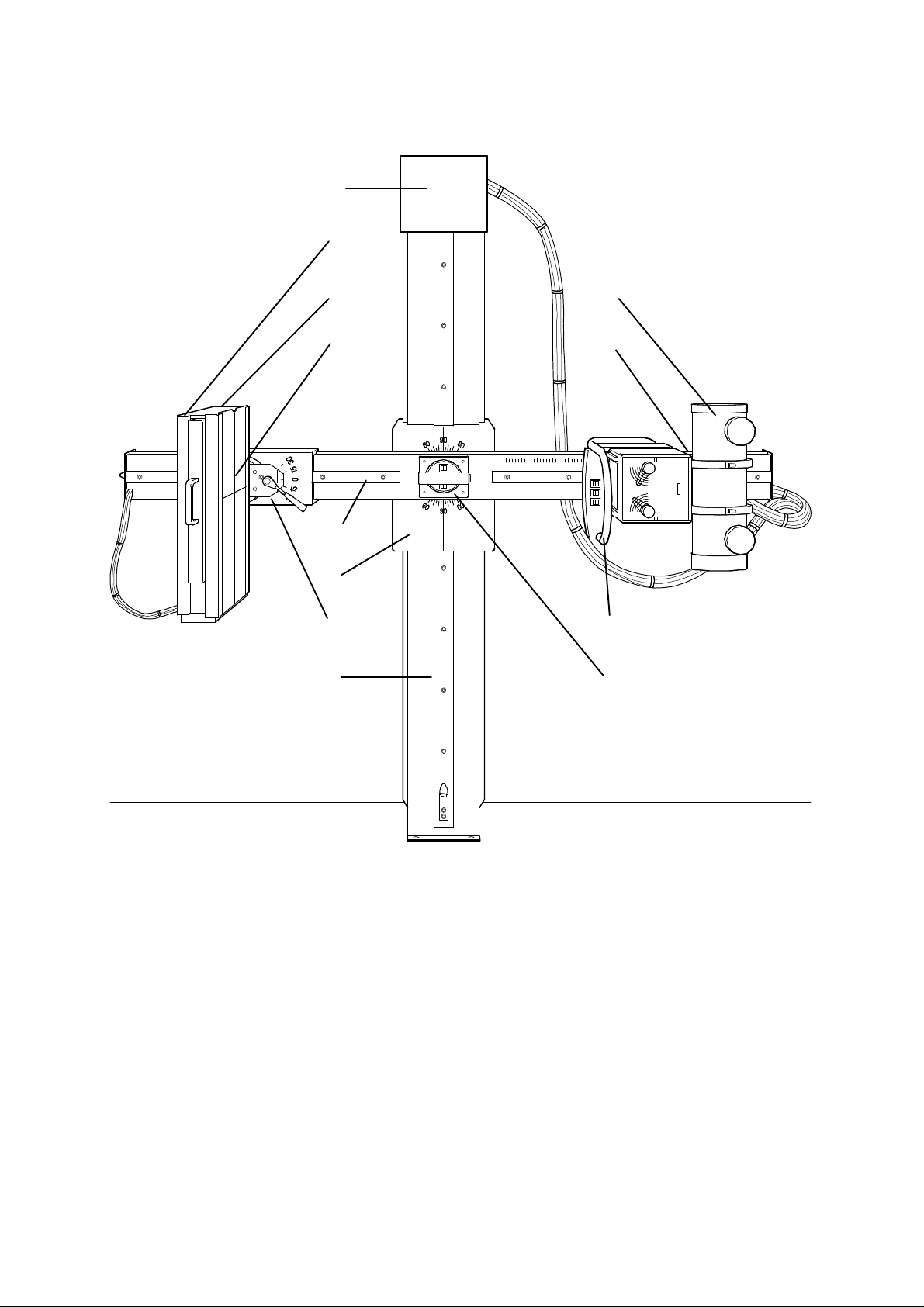
1.5. Component Designations
9
6
11 10
12 4
2
3
5 7
1 8
1 Column stand
2 Swivel arm
3 Vertical carriage
4 Tube carriage
5 Bucky carriage
6 Bucky support
7 Main control handle
8 Cental control grip
9 Top cover
10 X-ray tube and collimator
11 Bucky
12 Cover plate
0380 7224 - 4 of 34 - 07/99
Rev. 06 © 1999 Hans Pausch Röntgengerätebau Graf-Zeppelin-Str. 1 D-91056 Erlangen ALL RIGHTS RESERVED Ru
Page 5
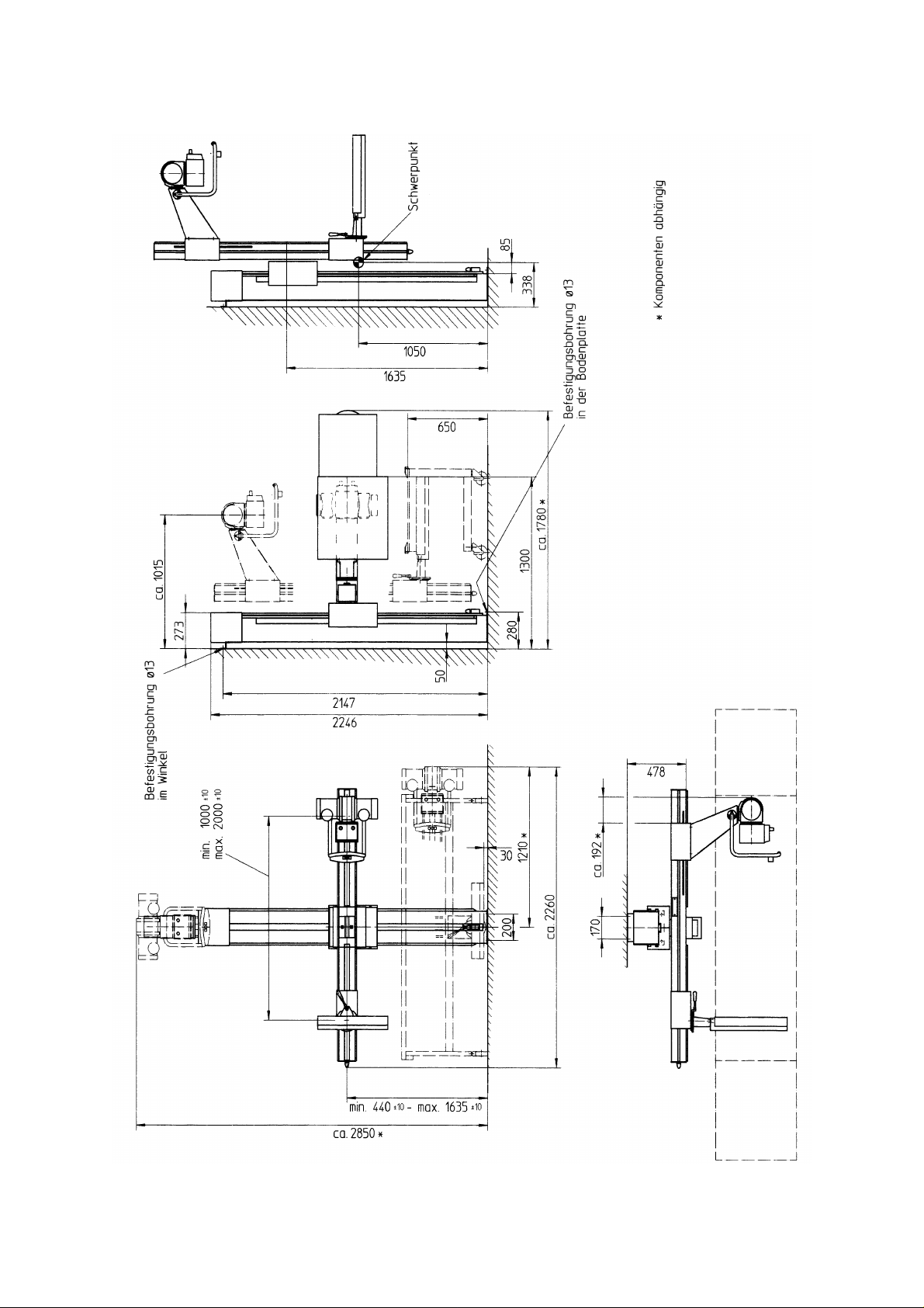
1.6 Dimensional Drawing
07/99 -5 of 34- 0380 7224
Rev. 06 © 1999 Hans Pausch Röntgengerätebau Graf-Zeppelin-Str. 1 D-91056 Erlangen ALL RIGHTS RESERVED Ru
Page 6

1.7 Power Connection
Requirement: At the beginning of mounting the unit all electrical connections and installations must been carried out according to the ordering contract about voltage and
frequency.
Nominal voltage: 115/230 V AC
Frequency: 50/60 Hz
Nominal current: 2 / 1 slow blow fuse
Power ratings: 230 VA
1.8 Special Tools and Measuring Instruments Required
Machinist's water level
Masonry drill, 12 mm (.472") diameter
1 spring scale 200 N
0380 7224 - 6 of 34 - 07/99
Rev. 06 © 1999 Hans Pausch Röntgengerätebau Graf-Zeppelin-Str. 1 D-91056 Erlangen ALL RIGHTS RESERVED Ru
Page 7
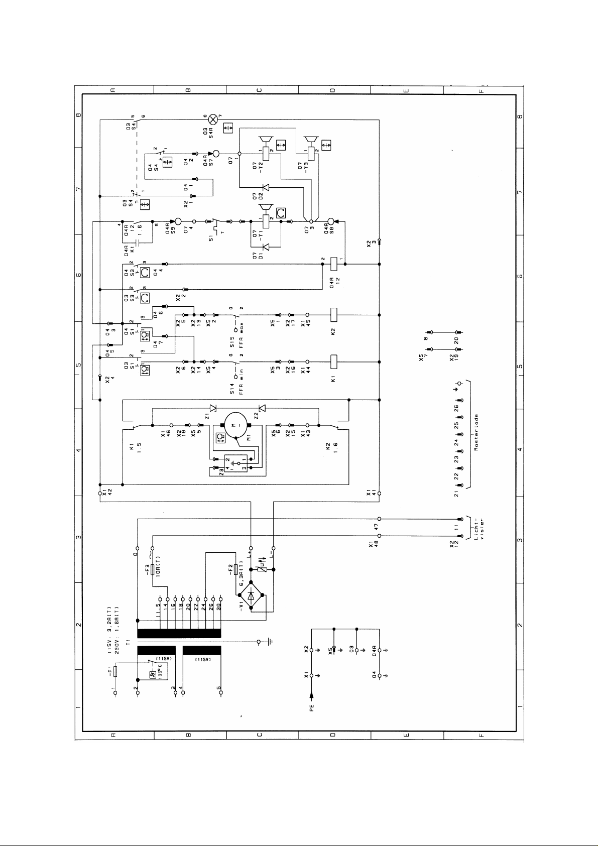
1.9 Schematics
07/99 -7 of 34- 0380 7224
Rev. 06 © 1999 Hans Pausch Röntgengerätebau Graf-Zeppelin-Str. 1 D-91056 Erlangen ALL RIGHTS RESERVED Ru
Page 8
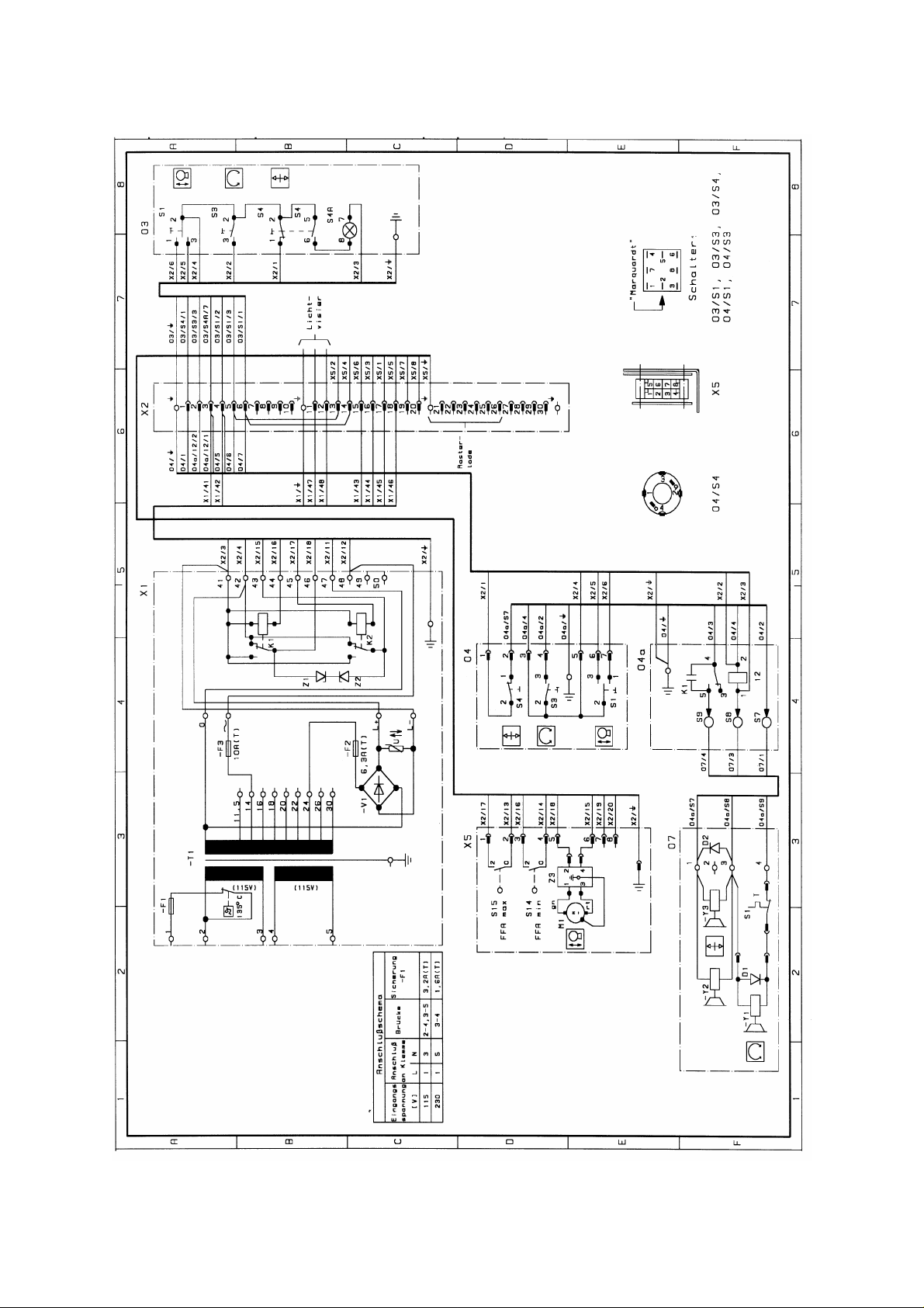
1.10 Wiring Diagram
0380 7224 - 8 of 34 - 07/99
Rev. 06 © 1999 Hans Pausch Röntgengerätebau Graf-Zeppelin-Str. 1 D-91056 Erlangen ALL RIGHTS RESERVED Ru
Page 9
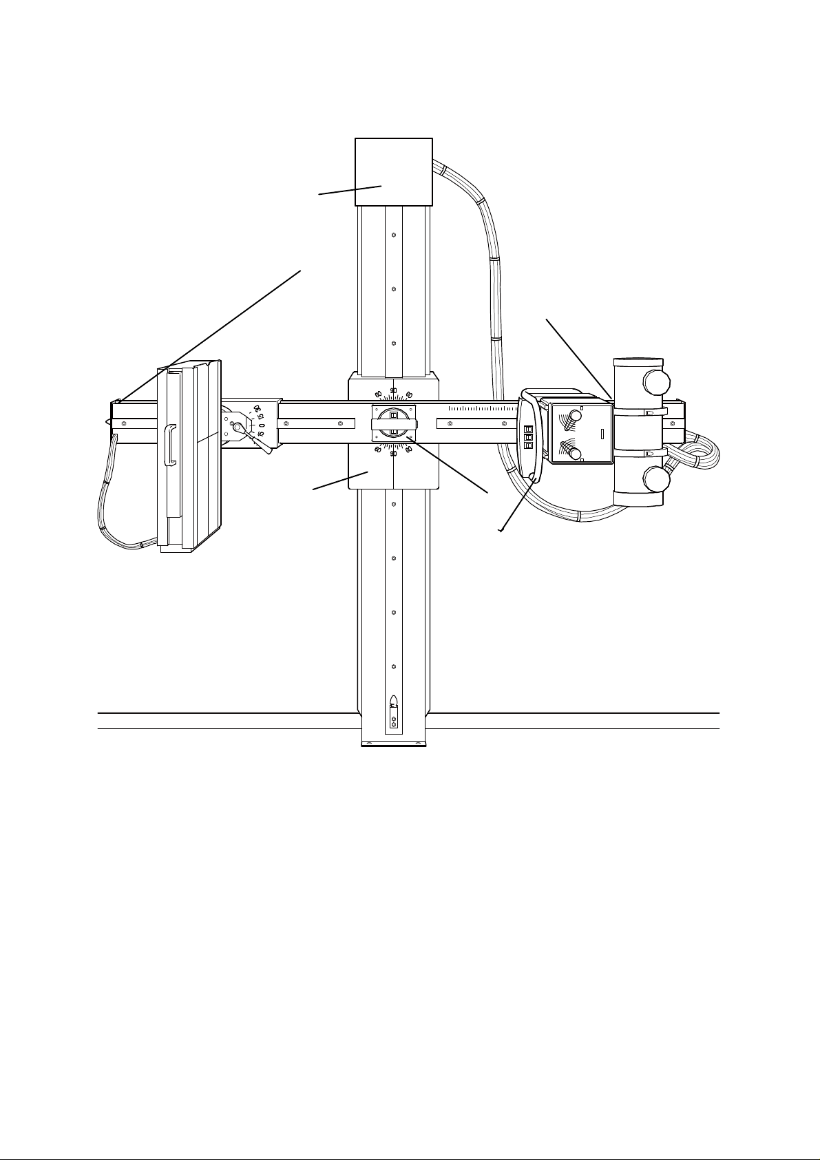
1.11 Physical Location of Electrical Components
X1
05
X2
07 04
1.12 Component Numbers and Designation
03
X1 Power supply
X2 Terminal strip
03 Main control handle
04 Cental control grip
X5 SID drive
07 vertical carriage
07/99 -9 of 34- 0380 7224
Rev. 06 © 1999 Hans Pausch Röntgengerätebau Graf-Zeppelin-Str. 1 D-91056 Erlangen ALL RIGHTS RESERVED Ru
Page 10
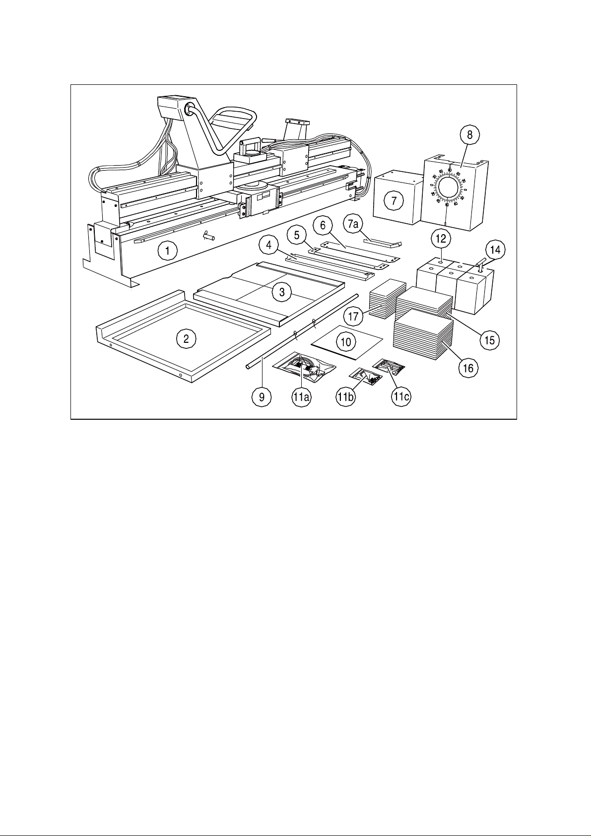
1.13 Component check list
1 Column stand with rotation arm, tube arm, control arm
2 Bucky support
3 Front plate (option - accessories)
4 Cable cover cap
5 Bucky fixing plate below
6 Bucky fixing plate above
7 Cap (head cover)
7a Cable guide (option - accessories)
8 Vertical carriage cover
9 Installation aid (lift tube)
10 Anti-slip mat
11a Fastening material Bucky
11b Fastening material tube
11c Fastening material for wall and floor
12 6 weight blocks à 12,5 kg
13
14 T-grip mounting aid
15 14 weight plates à 2 kg
16 14 weight plates à 2 kg
17 14 weight plates à 1 kg
0380 7224 - 10 of 34 - 07/99
Rev. 06 © 1999 Hans Pausch Röntgengerätebau Graf-Zeppelin-Str. 1 D-91056 Erlangen ALL RIGHTS RESERVED Ru
Page 11
2. Mounting of Unit
2.1 Site Preparation
Make unit site preparation according to dimensional drawing on page 5.The bore diameter
must be 12 mm. To assure all movements of the equipment pay attention to all movement
possibilities.
Note: The mounting points must be suitable for tensile strength of 1000 N pull.
For example: Liebig-safety bolts S12/65 for concrete floor tensile strength classification DIN
1045 B 15.
2.2 Uncrating
Remove top and side walls of the crate (not necessary with just protection packing). Take
out the Bucky support and accessories and unpack completely. Check the contents of each
box with dispatch note or order to assure that all items are located. Pay also attention to
page 10 1.13 Component check list.
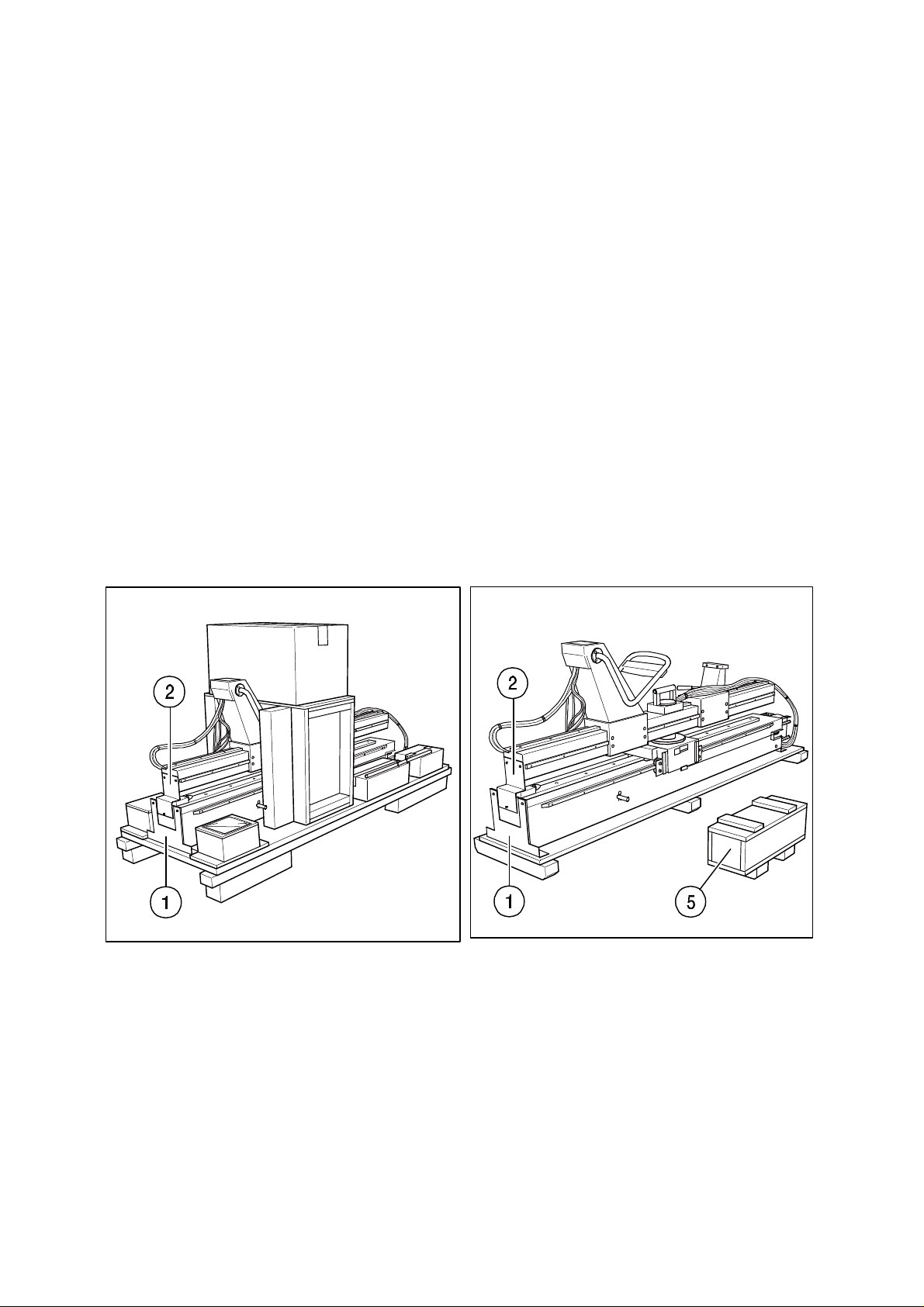
Fig. 1 Fig. 2
Mount low voltage unit (Fig. 27) onto the rope return block with the four stay bolts.
Move equipment with the transport palette to the installation place and assure that foot end
of the palette is approx. 1,5 m away from the installation wall.
07/99 -11 of 34- 0380 7224
Rev. 06 © 1999 Hans Pausch Röntgengerätebau Graf-Zeppelin-Str. 1 D-91056 Erlangen ALL RIGHTS RESERVED Ru
Page 12
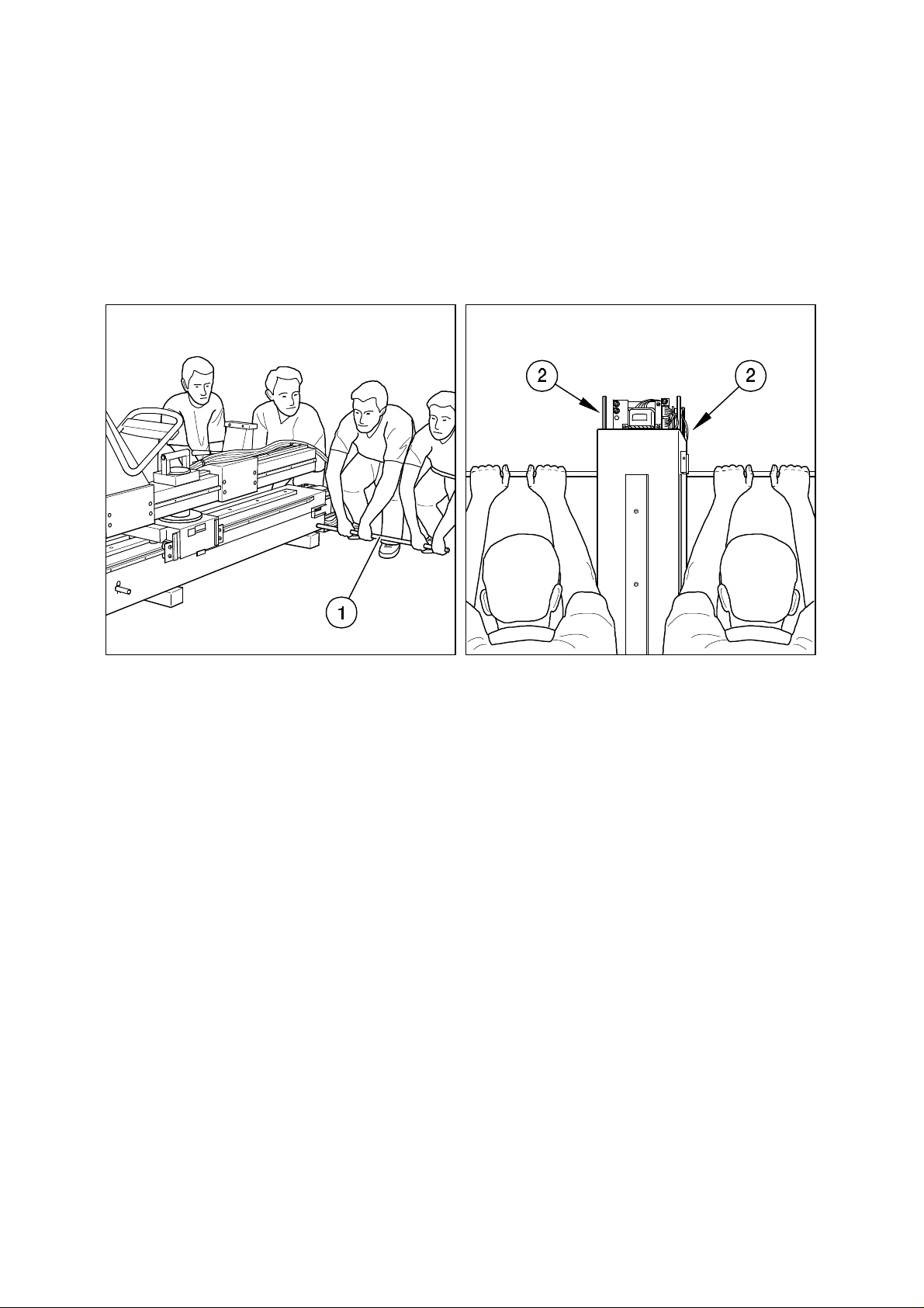
2.3 Unit preparation
Unsrew equipment (head- and foot side) from palette: Unscrew fastening angle
(Fig.1/Pos.1) respectively (Fig. 2/Pos. 1).
Remove transport security (Fig. 1/Pos. 2) respectively (Fig. 2/Pos. 2) of rotation arm.
Remove caps of small cases (Fig. 2/Pos. 5) and take out counterweight plates respectively
counterweight blocks carefully.
Fig.3 Fig. 4
2.4 Unit installation
Put installation aid (tube) (Fig. 3/Pos. 1) through the at the head side prepared bore hole of
the column stand and lay down anti-slip mat approx. 20 cm from the palette. Lift with four
men the installation aid and move approx. 30 cm to the foot side and mount. Rotate equipment and bring to installation place.
Attention: Do not use for lifting, bat for balancing !
Fasten temporarily onto the wall with two screws (Fig. 4/Pos. 2) and to the floor with two
screws.
2.5 Leveling the Unit
Align column stand with air level (Fig. 5/Pos. 13 - Fig. 6/Pos. 14) and tighten fastening
screws.
0380 7224 - 12 of 34 - 07/99
Rev. 06 © 1999 Hans Pausch Röntgengerätebau Graf-Zeppelin-Str. 1 D-91056 Erlangen ALL RIGHTS RESERVED Ru
Page 13
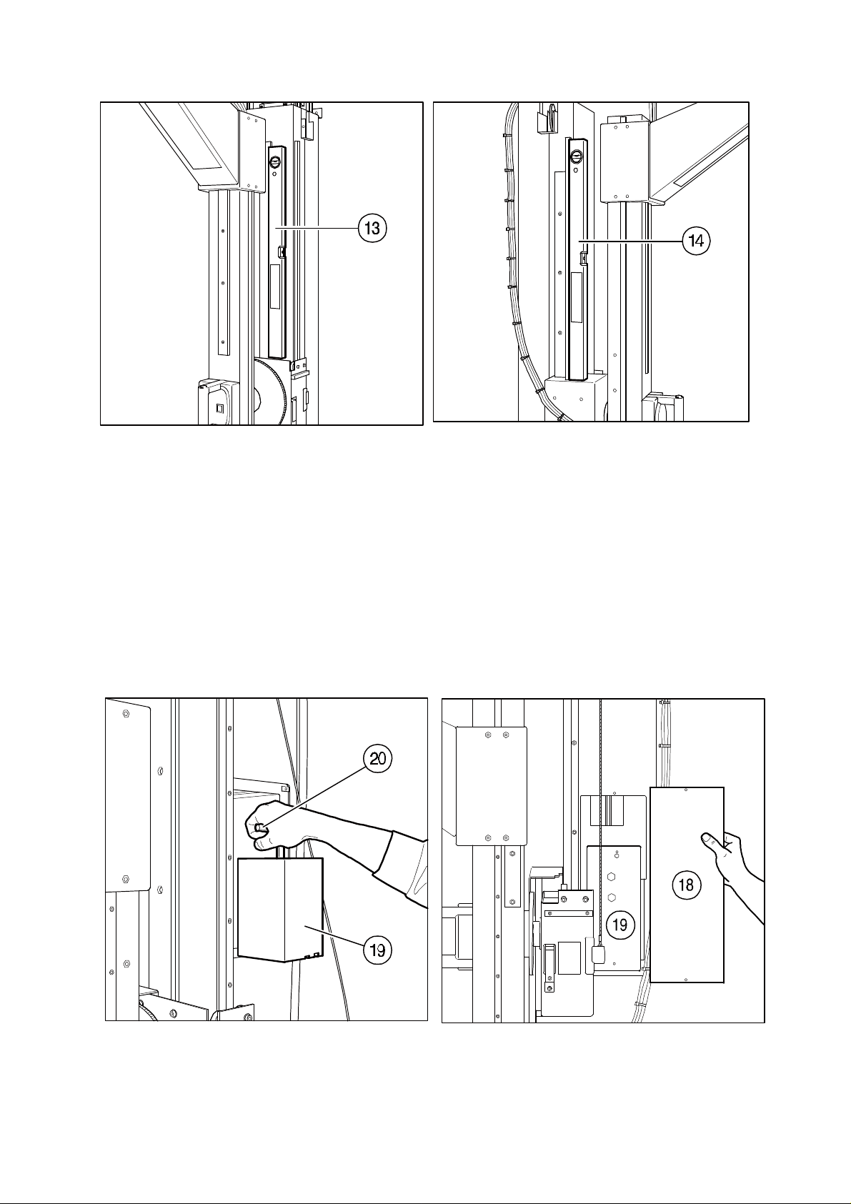
Fig. 5 Fig. 6
2.5.1 Loading of counterweights
Remove cover (Fig. 8/Pos. 18) from column stand and strap (Pos. 19) from counter weight
carriage. Insert counter weight blocks (Fig. 7/Pos. 19) with screwed in support grip (Pos. 20)
in counter weight carriage.
Attention:
Insert on three levels 2 counter weight blocks each and 7 counter weight plates each.
.
Fig. 7 Fig. 8
07/99 -13 of 34- 0380 7224
Rev. 06 © 1999 Hans Pausch Röntgengerätebau Graf-Zeppelin-Str. 1 D-91056 Erlangen ALL RIGHTS RESERVED Ru
Page 14
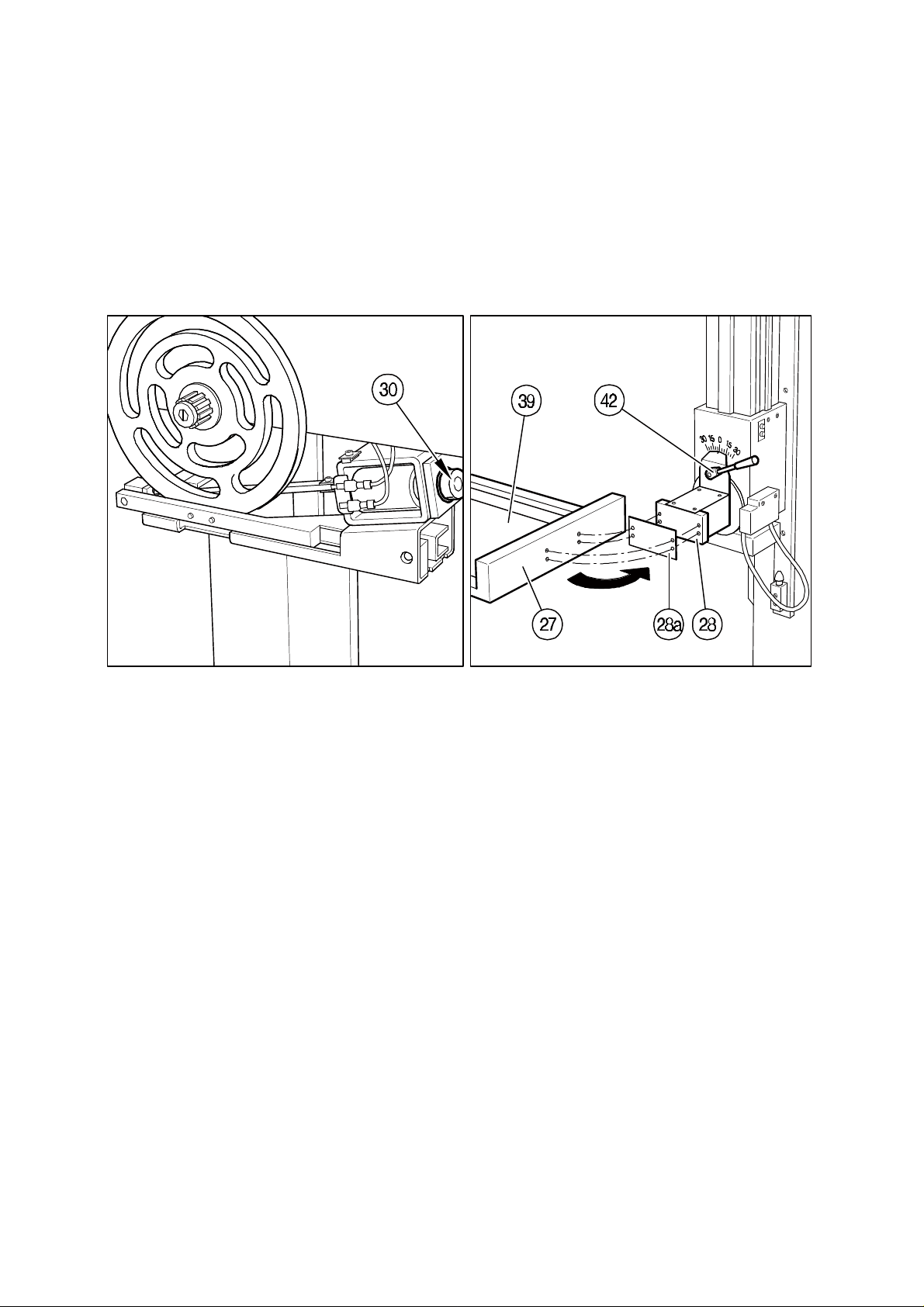
The adjustment will be done with counter balance plates. Ref. to section 3.3
Mount strap (Fig. 8/Pos. 19) on counter weight carriage and reinstall cover (Pos.18).
2.6 Mounting of Bucky Support
Put swivel arm in upright position, so that the Bucky carriage (Fig. 10/ Pos. 27) is at the
bottom (Fig. 10/Pos. 28). Mount Bucky support (Pos. 27) and lining plate (Pos. 28a) with
4 screws to Bucky carriage (Pos. 28).
Fig. 9 Fig. 10
2.7 Mounting of Control arm
Release the rotation brake while pushing onto the armature (Fig. 9/Pos. 30) and rotate rotation arm about 90° carefully. Dismount cover (Fig. 11/Pos. 31+29) from the tube support
(Pos. 32). Dismount control arm (Pos. 33) and remount again 180° rotated.
2.8 Mounting of X-Ray Tube and Collimator
Lift rotation brake while pushing onto the armature (Fig. 9/Pos. 30) and rotate rotation arm
carefully by 90°. Bring tube (Fig. 11/Pos. 34) to the tube support (Pos. 32) and fasten with
4 screws. Put collimator (Pos. 36) onto the tube (Pos. 34) and fasten.
Rotate again rotation arm by 180°.
Attention:
The weight counterbalance of the rotation arm is not counterbalanced.
There is a risk of accident !
0380 7224 - 14 of 34 - 07/99
Rev. 06 © 1999 Hans Pausch Röntgengerätebau Graf-Zeppelin-Str. 1 D-91056 Erlangen ALL RIGHTS RESERVED Ru
Page 15
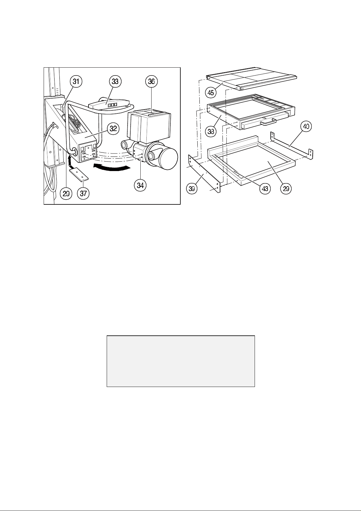
2.9 Mounting of Bucky
Liebel - Flarsheim -, Laufrasterlade P-, Philips - Bucky
Fig. 11 Fig. 12
Place Bucky (Fig. 12/Pos. 38) onto Bucky support (Pos. 29). Mount Bucky with fastening
means (Pos. 39, 40) to Bucky support (Pos. 29). Mount Bucky front cover (Pos. 45) to
Bucky.
2.10 Release of vertical drive
Dismount fall brake security (Fig. 15/Pos. 1). Dismount vertical carriage (Pos. 2) and fasten
the guide rails with two screws (Pos. 3). Take the support bolt (Fig. 16/Pos. 1) out of the
column stand.
Attention!
Bevor putting in operation:
Remove sipping bracket !
Attention:
Park fall brake security (Fig. 15/Pos. 1) and the vertical carriage security (Fig. 15 /Pos.2)
onto the vertical carriage according to Fig. 17 and store the support bolt (Fig. 16/Pos. 1)
safely. These parts are necessary for services.
07/99 -15 of 34- 0380 7224
Rev. 06 © 1999 Hans Pausch Röntgengerätebau Graf-Zeppelin-Str. 1 D-91056 Erlangen ALL RIGHTS RESERVED Ru
Page 16
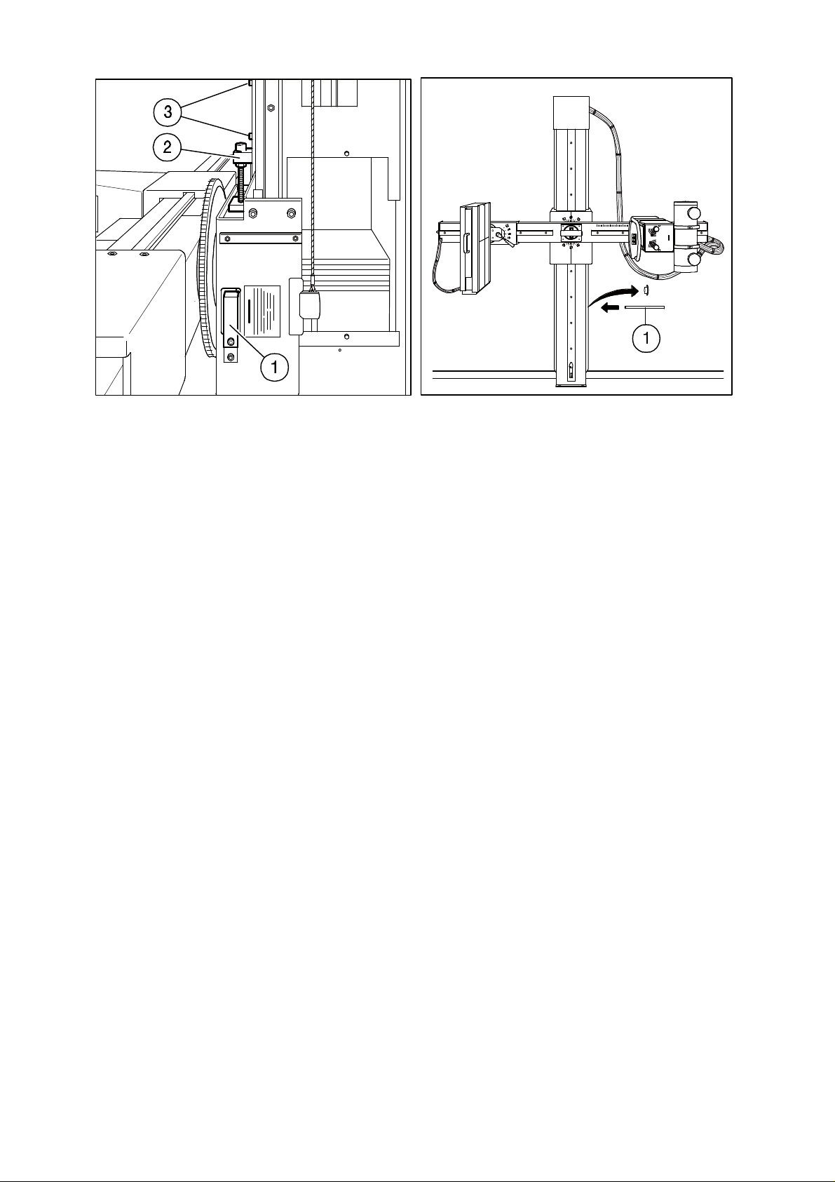
Fig. 15 Fig. 16
2.11 Electrical Connections
Connect control arm connection cable for the operating controls in the tube support (Fig.
11/ Pos. 32) to the terminal strip. Connect mains supply to the low voltage power supply at
the head piece.
Connect all electrical connections according to wiring diagram respectively the attached
wiring diagram.
2.12 Mounting of covers
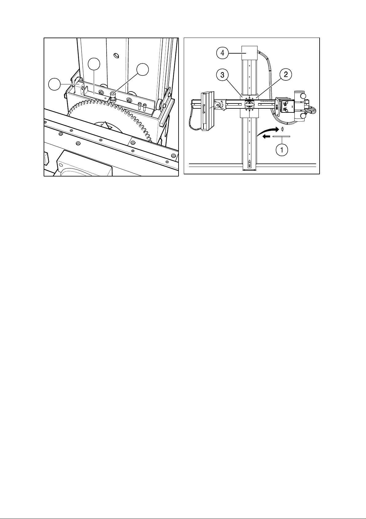
Put both half of the vertical carriage covers (Fig. 18/Pos. 2+3) on the vertical carriage and
fasten with 4 screws. Put cover (Fig. 18/Pos. 4) from above over power supply (head part)
and fasten with 4 screws.
0380 7224 - 16 of 34 - 07/99
Rev. 06 © 1999 Hans Pausch Röntgengerätebau Graf-Zeppelin-Str. 1 D-91056 Erlangen ALL RIGHTS RESERVED Ru
Page 17
1
2
3. Adjustments
3
Fig. 17 Fig. 18
(Factory adjustment and field change activity)
3.1 Bucky Tilt Adjustment
Put the swivel arm in upright position, so that the Bucky is at the bottom. Loosen lock
(Fig.10/ Pos. 42) and determine weight difference with means of a spring scale of the
Bucky angulation. In case of weight differences: remove Bucky and compensate
weight difference with trim weights. Reinstall Bucky.
3.2 Adjustment of Rotation
Put swivel arm in horizontal position, remove cover (Fig. 11/Pos. 29 and 31), adjust weight difference with trim weights (Fig. 11/Pos. 37) in tube support.
3.3 Adjustment of vertical carriage
Release vertical brake and fasten weight balance with spring scale. Drive vertical carriage
downwards (mid of travel way) until the sleeve of the counterbalance is at the same height
as the bore hole in the column stand for the support bolts and put support bolts
(Fig. 18/Pos. 1) through column.
Remove cap (Fig. 8/Pos. 18) from column stand and the strip (Pos. 19) from weight case.
Attention: Danger when the support bolt (Fig. 18/Pos. 1) is not properly placed in
the column.
07/99 -17 of 34- 0380 7224
Rev. 06 © 1999 Hans Pausch Röntgengerätebau Graf-Zeppelin-Str. 1 D-91056 Erlangen ALL RIGHTS RESERVED Ru
Page 18
Switch off power supply. Adjust weight difference with weight plates and insert in counterweight box. Install security sleeve (Fig. 8/Pos. 19) onto counterweight box and lock column
with cap (Pos. 18).
Remove support bolt (Fig. 18/Pos. 1) from column.
3.4 Adjustment of Rotational Lock
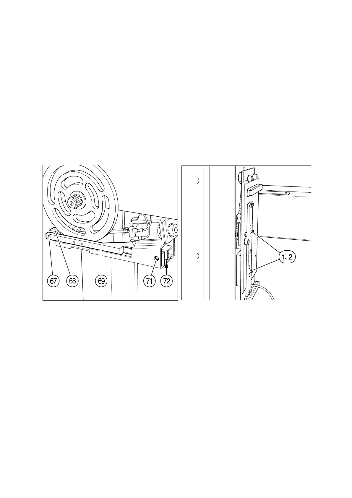
Remove the left and the right trim cover (Fig. 18/Pos. 2+3) of the vertical carriage.
Loosen counter screws (Fig. 19/Pos. 67). Turn adjusting nut (Pos. 68) clockwise for more
lock holding force. Tighten counter screw (Pos. 67) again.
Note:
The brake lever (Pos. 69) should be parallel to the edge of the vertical carriage. If necessary change position of lock screw (Pos. 71) and counter lock it with nut (Pos. 72) again.
Fig. 19 Fig. 20
3.5 Vertical Lock
Remove the left trim cover of the vertical carriage (Fig.18/Pos. 2+3). Loosen counter
nut (Fig. 20/ Pos. 1) and adjust the gap of the brake to 0.2 mm with set screw (Pos. 2).
Fasten counter nut again and install trim cover of the vertical carriage.
3.6 SID Pointer
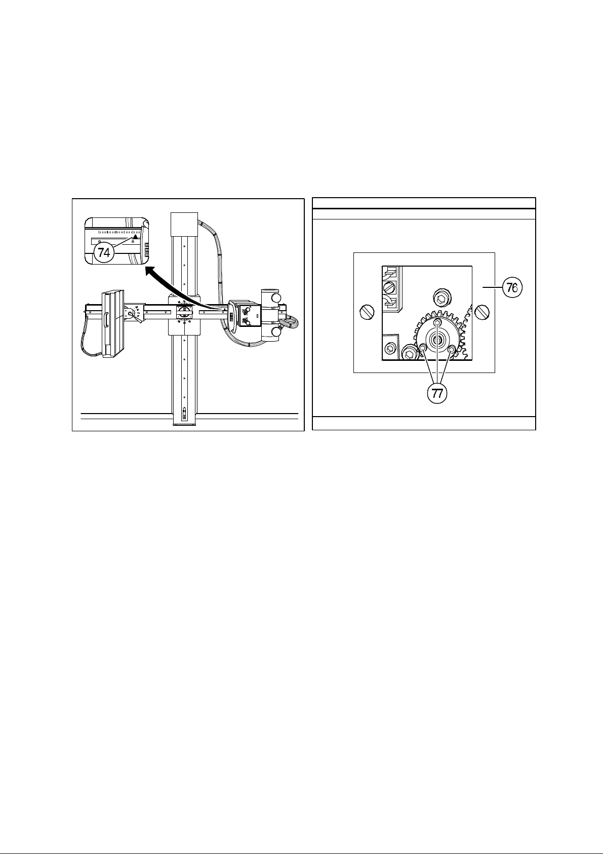
Determine SID - distance and adjust the pointer (Fig. 21/ Pos. 74) to desired position.
0380 7224 - 18 of 34 - 07/99
Rev. 06 © 1999 Hans Pausch Röntgengerätebau Graf-Zeppelin-Str. 1 D-91056 Erlangen ALL RIGHTS RESERVED Ru
Page 19
3.7 SID Drive Clutch
Remove cover (Fig.22/Pos. 76). Adjust the torque with means of the 3 screws (Pos. 77).
For higher torque turn screws (Pos. 77) clockwise.
Note:
The stop motion force of the Bucky- or tube carriage should be set to 150 N max. Secure
screws with locking dye and mount cover again.
Fig. 21 Fig. 22
3.8 SID End Switch
Remove end cover of swivel arm (Fig.23/Pos. 79). Drive SID to minimum distance possible. Loosen trip cam (Pos. 81) with socket wrench and turn the cam until switch (Pos.
82) is actuated. Tighten trip cam. Put SID to maximum distance, loosen trip cam (Pos. 83)
and turn it until switch (Pos. 84) is actuated. Fasten trip cam again.
Note: The SID is variable from 1 m to 2 m distance but can be limited in any intermediat
distance.
Install trim cover (Pos. 79) again.
07/99 -19 of 34- 0380 7224
Rev. 06 © 1999 Hans Pausch Röntgengerätebau Graf-Zeppelin-Str. 1 D-91056 Erlangen ALL RIGHTS RESERVED Ru
Page 20
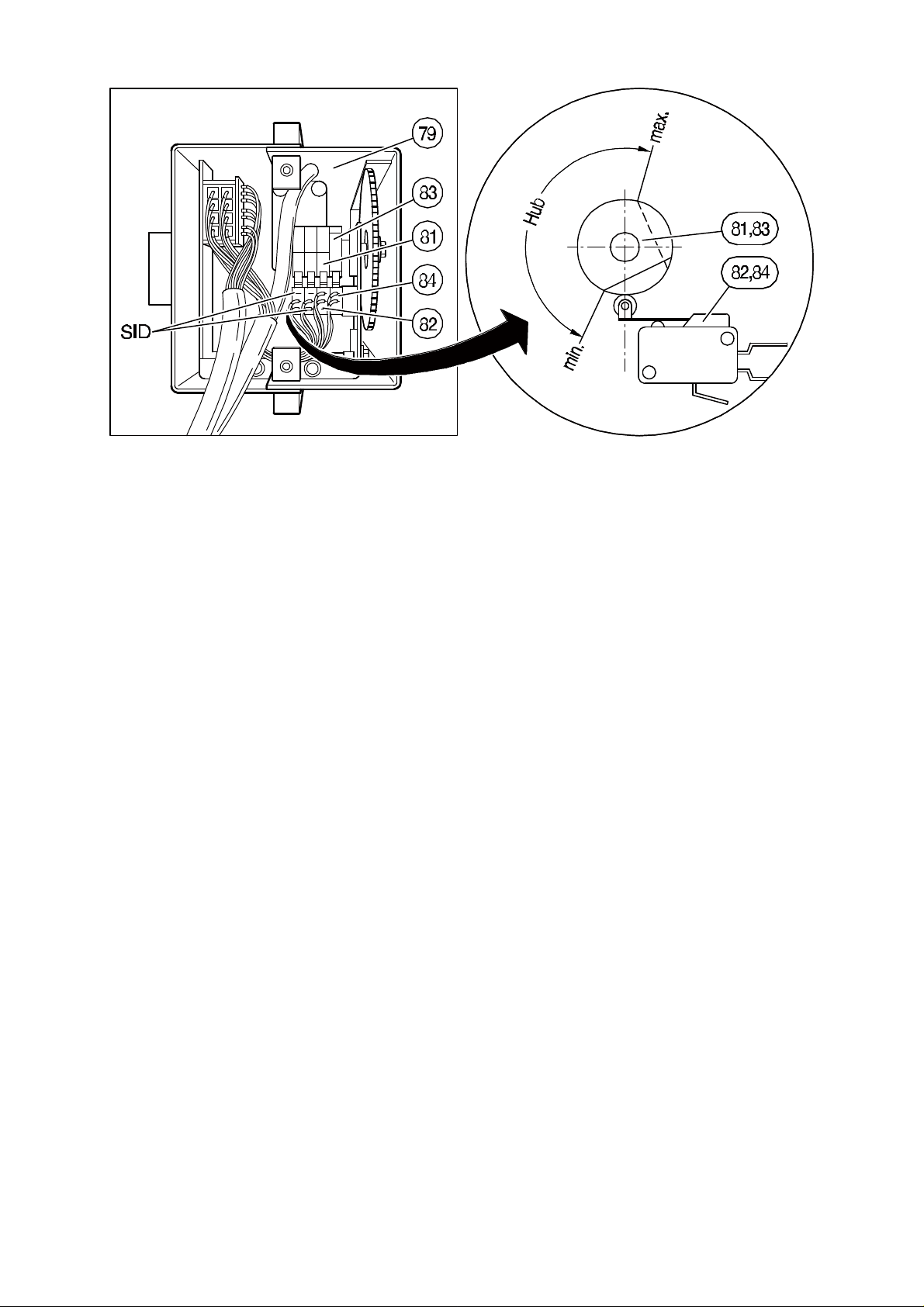
Fig. 23
0380 7224 - 20 of 34 - 07/99
Rev. 06 © 1999 Hans Pausch Röntgengerätebau Graf-Zeppelin-Str. 1 D-91056 Erlangen ALL RIGHTS RESERVED Ru
Page 21
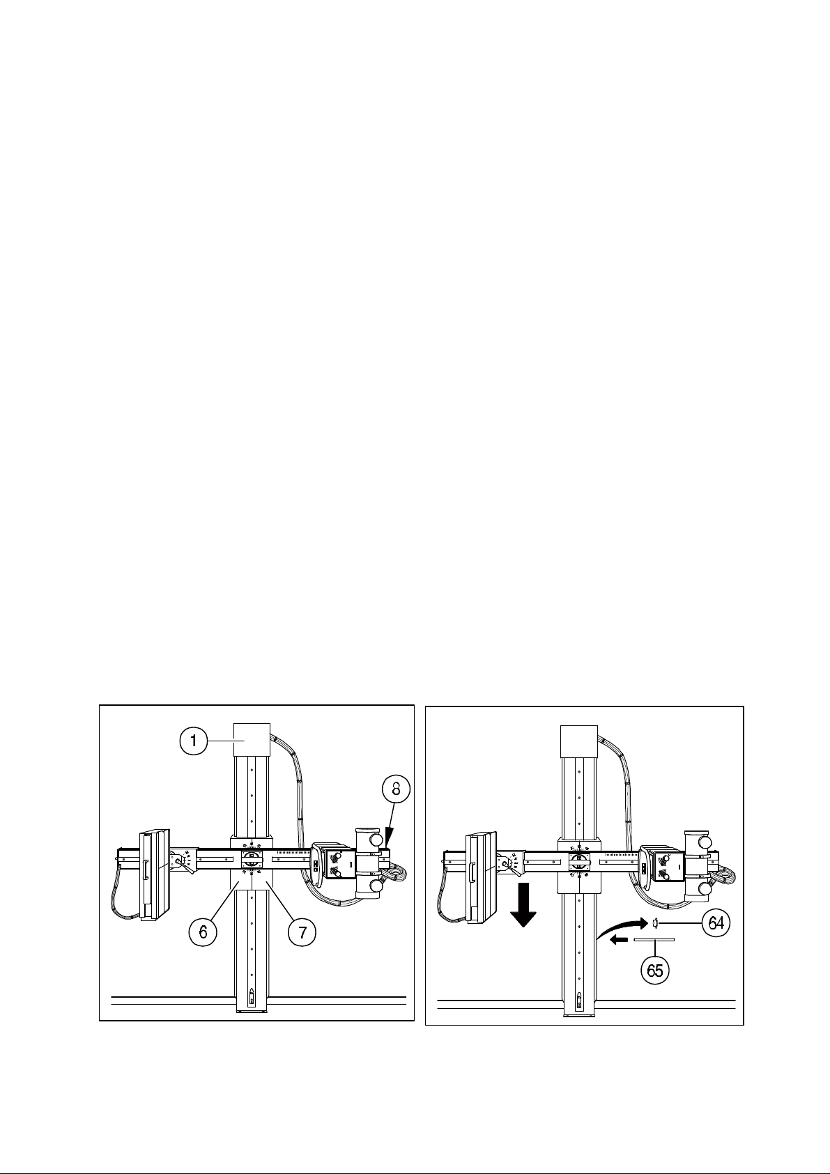
4. Technical Maintenance
4.1 Mechanical and Electrical Checks
The maintenance schedule described below is to be accomplished at 12-month intervals.
Whenever in the course of these procedures, parts of the unit must be moved electromotively, or if functional tests require power, disconnect the power as soon as the part has
reached the new position, or after the appropriate functional test sequence. Defective parts
must be replaced by genuine spare parts according to the spare parts list.
Use only non-acid grease for maintenance. Do not grease or oil ball bearings with sealing
washers.
Preparation: Turn off unit. Remove cover (Fig. 25/Pos. 1) the cover of the vertical
carriage (Pos. 6+7) and cover (Pos. 8)
Floor and wall Check all fastening screws and tighten if necessary. Torque 50 N.
mounting
Vertical car- Clean the guide rails of the column and check for damage. Slightly
riage grease the rails again.
Clean wire ropes (do not use any solvents) visually inspect the ropes for
traces of wear. Lightly apply lubricant.
Steel rope Clean steel rope (do not use fat solvents) and check upon damage.
Check on smooth running over entire travel range. At the slightest sign
of damage - (if there are 12 or more broken single lodes of the rope up
to 100 mm or 3 and more single lodes up to 10 mm or a single lode broken) - inform the user directly. Further use of the equipment could
endanger the security of patient and user. Do not use the equipment
until the defective rope has been replaced.
Attention: The exchange of the rope has to be done at least every 3 years
Fig. 25 Fig. 26
07/99 -21 of 34- 0380 7224
Rev. 06 © 1999 Hans Pausch Röntgengerätebau Graf-Zeppelin-Str. 1 D-91056 Erlangen ALL RIGHTS RESERVED Ru
Page 22

Safety brake: Functional check of the safety brake. Move vertical carriage all the way
down. Remove plastic caps (Fig. 26/Pos. 64) from both sides of the column. Insert steel rod (Fig. 26/Pos. 65). Lower the counter weight carriage
to rest on steel rod. Lift up the vertical carriage a little bit and let go.
The carriage must hold by the safety catch.
Lift up the vertical carriage again while pulling the wire rope upwards to
release the safety catch. Then slowly lower the vertical carriage until it
is held by the wire rope. Move counter weight carriage all the way up.
Remove steel rod and close up holes with plastic caps.
Check function of lock and tighten if necessary. Therefor adjust the
counter locked screw (re. to section 3.5).
Rotational lock Check function of the rotational lock. Should hold 300 N at the
end of the swivel arm (1m at radius), adjust if necessary. Ref. to section
3.4
Swivel arm Clean guide rails and check for traces of wear. Apply lubricant lightly.
SID-adjustment Clean the chain and regrease lightly. Check end switches; adjust if
necessary. Re to sec. 3.8.
Check slip clutch and adjust if necessary. Re. to sec. 3.7.
Tighten and adjust tension of the chain or fastening points at the Bucky
carriage or tube support.
Bucky carriage Check for proper fit of all mounting screws and tighten if necessary.
Check brake lever function of the Bucky tilting movement. Relocate
brake lever if necessary.
Tube carriage Check for proper fit of all mounting screws and tighten if necessary.
Check mounting screws of X-ray tube and control arm.
Electrical Check all electrical cables for damage, proper routing and strain relief.
checks Check all ground connections. All exposed deadmetal or other conductive
parts that are exposed to contact during any servicing operation, including maintenance and repair shall be connected to the equipment
grounding terminal and must carry less than 0.1 ohms resistance.
Control arm Check all electrical switch functions of the unit. Replace defective
and main switches.
Handle
Final work Clean unit and mount all trim covers again.
0380 7224 - 22 of 34 - 07/99
Rev. 06 © 1999 Hans Pausch Röntgengerätebau Graf-Zeppelin-Str. 1 D-91056 Erlangen ALL RIGHTS RESERVED Ru
Page 23
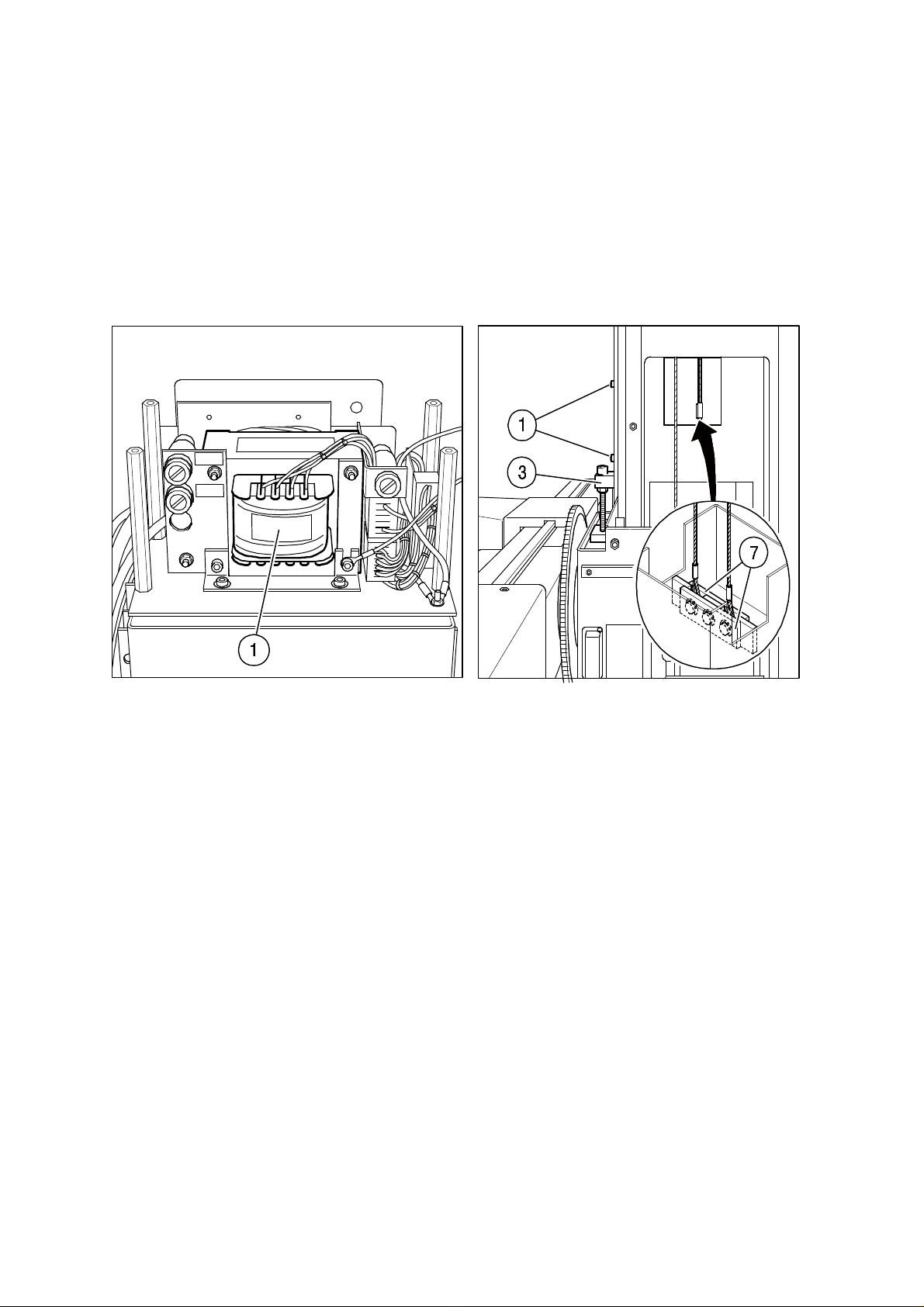
Changing Remove cover cap (Fig. 25/Pos. 1), carriage cover (Pos. 6+7) and low volt-
wire rope: age supply (Fig. 27/Pos. 1). Take plastic caps (Fig. 26/Pos. 64) out of
column.
Drive vertical carriage downwards (mid of travel way) until the sleeve of the
counterbalance is at the same height as the bore hole in the column stand
for the support bolts and put support bolts (Fig. 26/Pos. 65) through column.
Attention:
Danger when the support bolt (Fig. 18/Pos. 1) is not properly placed in
the column.
Fig. 27 Fig. 28
Remove both screws (Fig. 28/Pos. 1). Take vertical carriage security (Pos.
1) out of park position (Fig. 29) and mount to guide rail. Lift vertical carriage approx. 15 mm with tension screw (Fig. 28/Pos. 3). Dismount connection board (Pos. 7) from counterbalance.
Loosen both steel ropes on vertical carriage (Fig. 31/Pos. 1 + Fig. 32/Pos.
1). Lift pulley carrier (Fig. 30/Pos. 1) with steel robes. Remove robe pulley
(Fig. 30/Pos. 2+3) out of pulley carrier and dismount old steel robes. Insert
new steel robes carefully over robe pulley into pulley carrier.
07/99 -23 of 34- 0380 7224
Rev. 06 © 1999 Hans Pausch Röntgengerätebau Graf-Zeppelin-Str. 1 D-91056 Erlangen ALL RIGHTS RESERVED Ru
Page 24
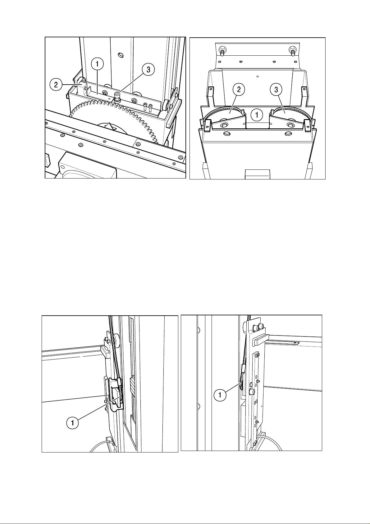
Fig. 29 Fig. 30
Reinsert pulley carrier into column stand. Hook up rope ends at vertical
carriage and connecting piece and mount to counterweight.
Attention: Wire ropes must not be damaged nor twisted.
Let off vertical carriage with tension screw and loosen at the same time
safety brake by pulling rope upwards and slowly lower vertical carriage
until it hangs at the counterweight.
Take bolt out of column and put plastic caps onto the holes.
Install low voltage supply, carriage cover and cover cap again.
Remove vertical carriage security (Fig. 28/Pos. 1) again and park.
Fig. 31 Fig. 32
0380 7224 - 24 of 34 - 07/99
Rev. 06 © 1999 Hans Pausch Röntgengerätebau Graf-Zeppelin-Str. 1 D-91056 Erlangen ALL RIGHTS RESERVED Ru
Page 25

4.2 Functional checks
Swivel arm Move swivel arm through its entire range of rotation.
Easy movement?
Quiet running?
Save locking in any working position?
Proper working of the brake?
Motorized SID Drive through entire travel range.
Quiet running?
Proper function of slip clutch with 150 N counter force applied?
Proper functioning of the limit switches in its end position?
Bucky tilt Loosen Bucky lock and turn Bucky 45 °
motion
Proper working of the brake?
Save locking in any working position?
Positive detent at 0 °?
Vertical Move the vertical carriage thru its entire range of vertical travel.
movement
Proper working of the locks in any working position?
Quiet running?
Twist-free running of the wire ropes?
Easy motion?
Cushioned end stops at the end of travel?
07/99 -25 of 34- 0380 7224
Rev. 06 © 1999 Hans Pausch Röntgengerätebau Graf-Zeppelin-Str. 1 D-91056 Erlangen ALL RIGHTS RESERVED Ru
Page 26
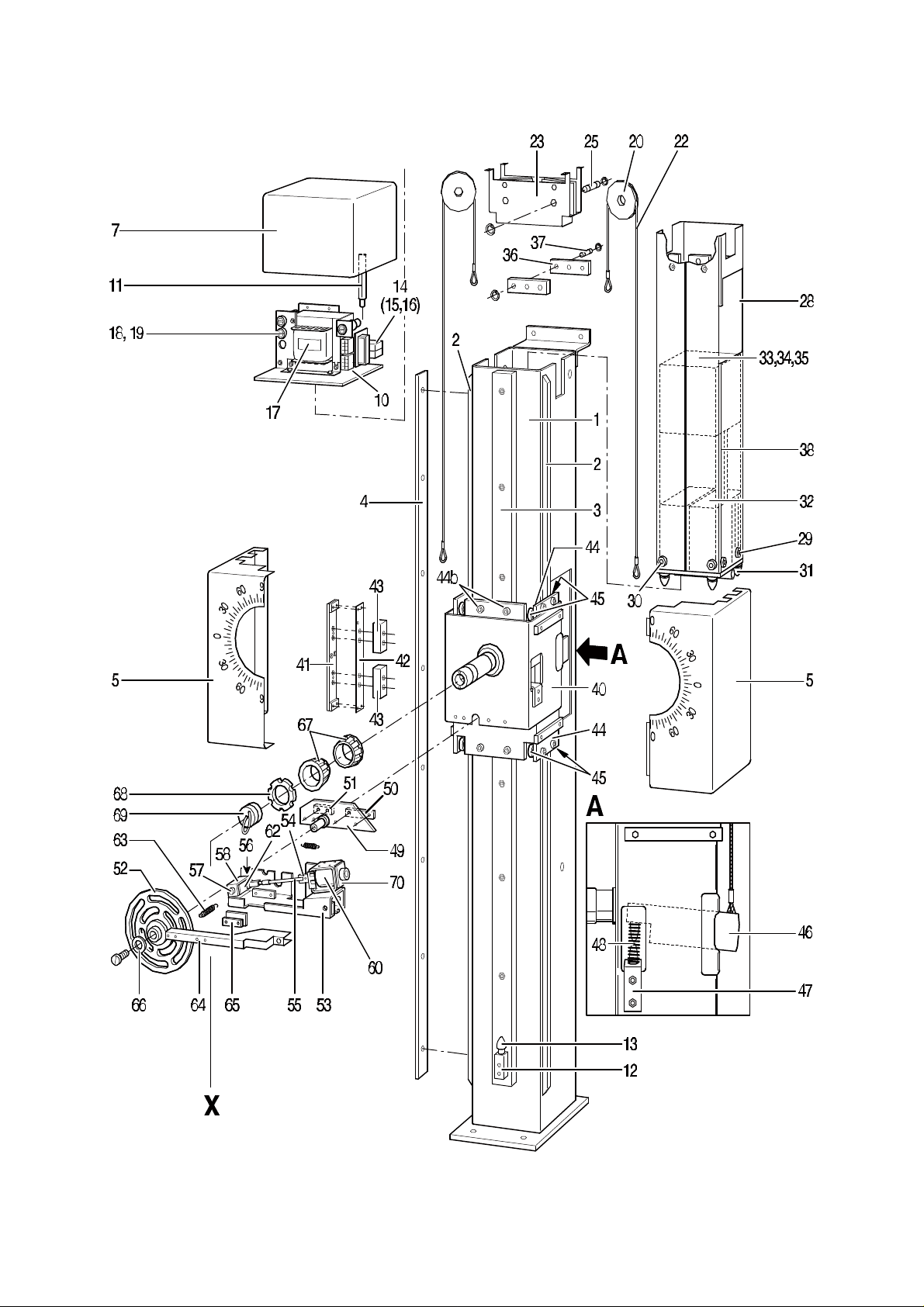
4.4 Spare Parts
0380 7224 - 26 of 34 - 07/99
Rev. 06 © 1999 Hans Pausch Röntgengerätebau Graf-Zeppelin-Str. 1 D-91056 Erlangen ALL RIGHTS RESERVED Ru
Page 27
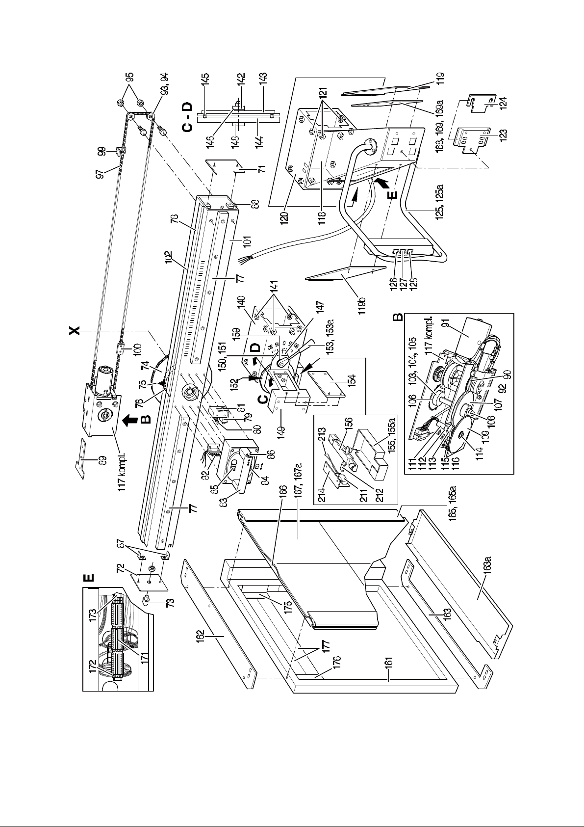
4.3.1 Spare Parts
07/99 -27 of 34- 0380 7224
Rev. 06 © 1999 Hans Pausch Röntgengerätebau Graf-Zeppelin-Str. 1 D-91056 Erlangen ALL RIGHTS RESERVED Ru
Page 28

4. Spare Parts List
List Part Names / Ordering Numbers
Failed spare parts may be replaced only with original parts as listed below. When ordering
spare parts, always indicate serial number of unit and complete number of part. The exchange of parts or elements may only be carried out by ourselves or by qualified personnel
being authorized to do so.
See also chapter "Safety Notes".
REF-No. Name Part.-No.
1 Column 0380 1550
2 Rail 0380 1541
3 Rail 0380 1542
4 Brake Rail 0380 1543
5 Trim Cover 0380 0175a
6
7 Top Trim Cover 0380 1585
8
9
10 Mounting Plate 0380 0032
11 Stud 0380 0078
12 Stop 0380 0074b
13 Parabolic Spring 0005 0103b
14 PC Board complete 0380 0038
15 Relay 0006 0111
16 Clamp 0006 0109
17 Low Voltage Power Supply 0006 0449
18 Fuse Cap (5 x 10) 0006 0152a
19 Fuse Cap (6,3 x 32) 0006 0152b
20 Pulley 0381 0930
21 0006 0429
22 Wire Rope 0381 0336c
23 Tub 0381 0327
24 Ball Bearing DIN 625 2400 0016
25 Bolt for Pulley 0381 0330
26 Plug holder Phi 0380 2109
27 Not used
28 Counter Weight Carriage 0380 1570
29 Slider 0380 0211c
30 Slider 0380 1578
31 Parabolic Spring 0380 0212
32 Trim Weight 1,85kg 0380 1571a
33 Trim Weight 0,95 kg 0380 1572a
34 Trim Weight 1,85 kg 0380 1574
35 Trim Weight 0380 1572a
36 Ledge 0381 0339
37 Bolt 0381 0338
38 Weight 2 kg 0380 1573b
39 Handle 0380 1595
40 Vertical Carriage comp. 0380 0050
0380 7224 - 28 of 34 - 07/99
Rev. 06 © 1999 Hans Pausch Röntgengerätebau Graf-Zeppelin-Str. 1 D-91056 Erlangen ALL RIGHTS RESERVED Ru
Page 29

REF-No. Name Part-No.
41 Bridge 0380 1600
42 Laminated Spring 0627 0682
43 Solenoid 0006 0603
44 Roller 0380 1224
44b Roller 0380 1229
45 Roller 0380 0060b
46 Safety Catch 0381 0794b
47 Bearing 0381 0790
48 Spring 0005 0136k
49 Holding Plate 0380 0888
50 Nut Plate 0380 0406
51 Nut Plate 0380 0407
52 Brake Disc assembly 0380 0410
53 Bracket 0380 0895
54 Link 0380 0394
55 Rod 0380 0886
56 Adjusting Screw 0380 0389
57 Lock Nut 0380 0882
58 Set of Links 0380 0884a-c
59 Not used
60 0380 0540
61 U-Roller 0380 0871
62 Not used
63 Spring 0005 0040o
64 Lever comp. 0380 0384
65 Brake Set 0380 0398
66 Disc 0380 0414
67 Bearing DIN 720 32009X 2400 0031
68 T-Nut 0380 0091
69 Slip Ring 0380 0156
70 Solenoid 0006 0175
71 Cover 0380 2103
72 Cover 0380 2104
73 Parabolic Spring 0005 0103a
74 Gear Wheel 0380 0359
75 Pointer 0380 0105
76 Ring 0380 0094
77 Front Rail 0380 0104
78 Top Rail 0380 0102
79 Relay 0006 0111
80 Carbon Brush 0006 0200
81 Bracket 0380 0310
82 Plug 0006 0504c+d
83 Main Handle 0380 2110
84 Commutator Switch 0006 0182b
85 Commutator Switch 0006 0182a
86 Push Button Switch 0006 0651ca
87 Angle 0380 0101
88 Rail 0380 0103
89 Nut Plate 0380 0127
90 Sprocket 0380 0577
91 Motor 0006 0365
92 Slip Clutch 0005 0214a
07/99 -29 of 34- 0380 7224
Rev. 06 © 1999 Hans Pausch Röntgengerätebau Graf-Zeppelin-Str. 1 D-91056 Erlangen ALL RIGHTS RESERVED Ru
Page 30

REF-No. Name Part-No.
93 Guide Pulley 0380 0096
94 Ball Bearing DIN 625 2400 0015
95 Insert Bushing 0380 0098
96 Washer 0380 0099
97 Single Roller Chain 0380 0107a
98 Single Roller Chain 0380 0107b
99 Chain Support 0380 1014
100 Connecting Angle 0380 1013
101 Swivel Arm Support 0380 0092
102 Swivel Arm Support 0380 0093
103 Bearing Bushing 0380 0123
104 Ball Bearing DIN 625 6000 2400 0017
105 Spacer Bushing 0380 0128
106 Chain Wheel 0380 0585
107 Sprocket 0380 0578
108 Spur Gear 0380 0120
109 Tooth Lock Washer 0380 0119
110 Shaft 0380 0576
111 Cam Shaft 0380 0582
112 Switch Cam 0380 0117a
113 Switch Cam 0380 0117b
114 Shoulder Bolt 0380 0114
115 Switch 0006 0184
116 Insulating Plate 0006 0257a
117 Motor Drive Assembly 0380 0570
118 Tube Shield Holder 0380 2150
119 Cover 0380 2165
120 Tube Carriage 0380 0141
121 Pulley 0380 0136
122
123 Fastening Plate 0380 0334
124 Adjusting Plate 0380 0335
125 Operating Console 0380 2200
126 Toggle Switch 0006 0182a
127 Toggle Switch 0006 0182b
128 Toggle Switch 0006 0182c
129
130
131
132
133
134
135
136
137
138
139
140 Bucky Carriage 0380 0174
141 Pulley 0380 0136
142 Adjusting Nut 0380 0226
143 Intermediate Disc 0380 0225
0380 7224 - 30 of 34 - 07/99
Rev. 06 © 1999 Hans Pausch Röntgengerätebau Graf-Zeppelin-Str. 1 D-91056 Erlangen ALL RIGHTS RESERVED Ru
Page 31

REF-No. Name Part-No
144 Brake Disc 0380 0224
144b Brake Disc set 0386 0364
145 Steel Ball DIN 5401 7/32" 2900 0003
146 Bearing Disc 0380 0221
147 Mounting Bracket 0380 0222
148 Shoulder Bolt 0380 0220
149 Connector 0380 0312
150 Brake Shoe 0380 0237
151 Brake Shoe with Spring 0380 0239
152 Shim 0380 0242
153 Handle 0380 0305b
153a Ball Handle 0380 0305a
154 Lid 0380 0313
155 Trim Cover (EUROPA) 0380 0235
155a Trim Cover (USA) 0380 1033
156 Catch 0380 0228
157
158 Sleeve 0380 0307
159 Washer 0389 0268
160
161 Bucky Support (Phi, LF,ES) 0380 1610a
162 Fastening Plate 0352 1620
163 Fastening Plate 0380 1621
163a Cover 0380 1622
164
165 T-Slotted Rail 0370 0746
165a T-Slotted Rail (Phi) 0352 0469
166 Frame 0370 0704
167 Bucky Cover Plate 0370 0718
167a Bucky Cover Plate (Phi) 0370 0715
168 Weight 0.5 kg 0380 0332
169 Weight 7 kg 0380 0331a
169a Weight 3 kg 0380 0331b
170
171 Terminal Strip 0006 0617a
172 Ground Stud 0006 0525
173 Rail for Terminal Strip 0110 0313a
174
175 Angle 0380 1017a
176 Angle 0380 1017b
177 Weight 0380 0280a
178 Plate 0380 1015
07/99 -31 of 34- 0380 7224
Rev. 06 © 1999 Hans Pausch Röntgengerätebau Graf-Zeppelin-Str. 1 D-91056 Erlangen ALL RIGHTS RESERVED Ru
Page 32

4.5 Maintenance Certificate
The maintenance according to the attached maintenance instructions has been carried
out. Any parts replaced were original spare parts as shown on the list.
Replaced parts (List Pos. no. only)
----------------------------------------------------------------------------------- Date Name of company Signature
Replaced parts (List Pos. no. only)
----------------------------------------------------------------------------------- Date Name of company Signature
Replaced parts (List Pos. no. only)
----------------------------------------------------------------------------------- Date Name of company Signature
Replaced parts (List Pos. no. only)
---------------------------------------------------------------------------------- Date Name of company Signature
0380 7224 - 32 of 34 - 07/99
Rev. 06 © 1999 Hans Pausch Röntgengerätebau Graf-Zeppelin-Str. 1 D-91056 Erlangen ALL RIGHTS RESERVED Ru
Page 33
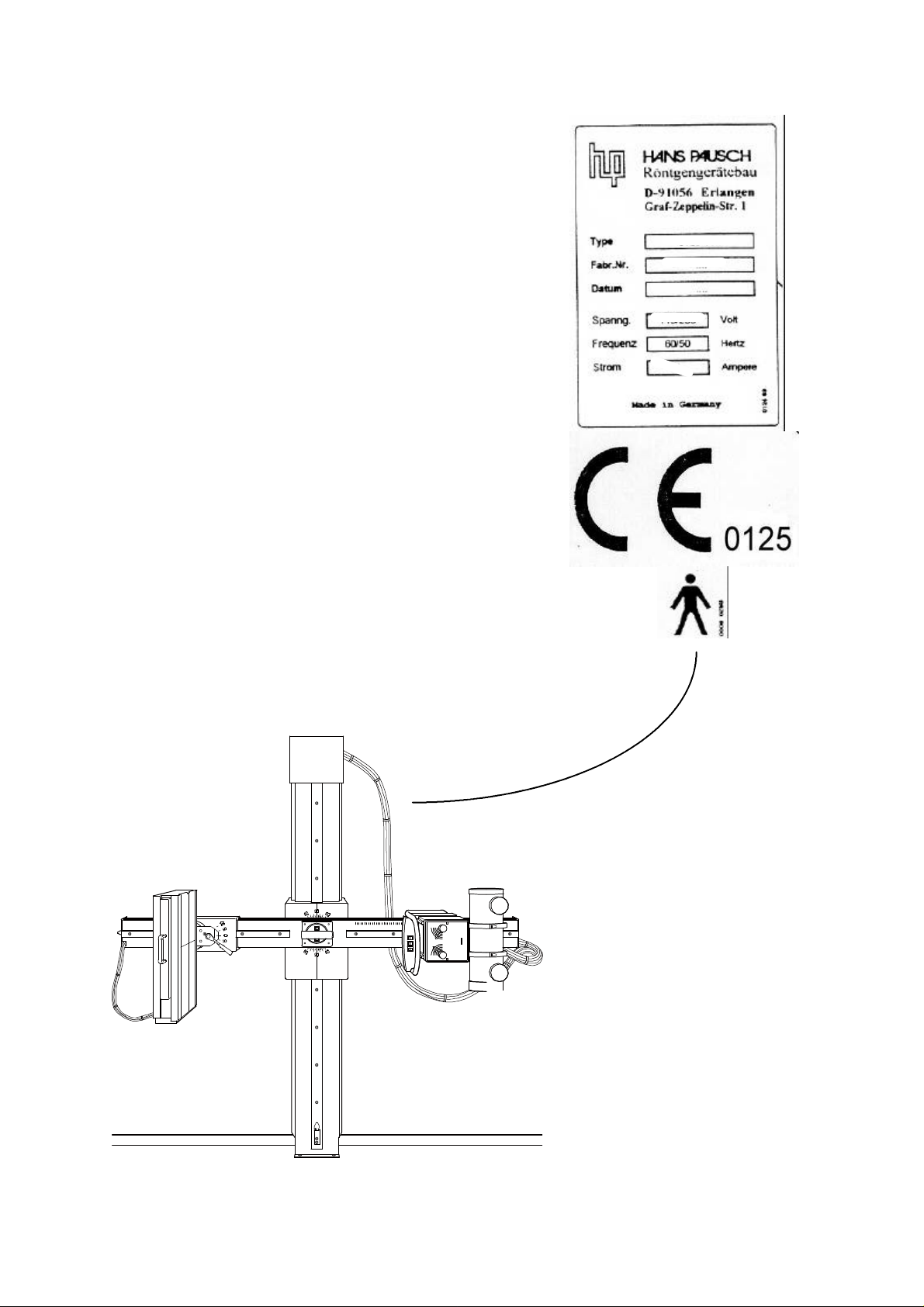
4.6 Name Plate Location
07/99 -33 of 34- 0380 7224
Rev. 06 © 1999 Hans Pausch Röntgengerätebau Graf-Zeppelin-Str. 1 D-91056 Erlangen ALL RIGHTS RESERVED Ru
Page 34

Subject to technical alterations TV/Ru
0380 7224 - 34 of 34 - 07/99
Rev. 06 © 1999 Hans Pausch Röntgengerätebau Graf-Zeppelin-Str. 1 D-91056 Erlangen ALL RIGHTS RESERVED Ru
 Loading...