


Mod.
DS1093-582
1093
IP H.265 Fish Eye Cameras
. ..
UFO 4K Ref. 1093/185FE - UFO 5M Ref. 1093/186BN
Canister 5M Ref. 1093/187C
USER MANUAL

ENGLISH
LIST OF CONTENTS
1 Introduction ................................................................................................................................................4
2 Product Description ..................................................................................................................................5
2.1 Technical features .....................................................................................................................5
2.2 Opening the Box ........................................................................................................................6
2.3 Warnings ...................................................................................................................................6
3 Overview .....................................................................................................................................................8
3.1 Range of Application .................................................................................................................8
3.2 Product description ....................................................................................................................8
3.3 Operating environment ..............................................................................................................9
4 Device Connection ....................................................................................................................................9
4.1 IP Camera Connector Layout (Where Present) ........................................................................9
5 Operating instructions ........................................................................................................................... 10
5.1 Connection Check .................................................................................................................. 10
5.2 Device Searching ................................................................................................................... 11
5.3 Installation of Controls and Login to System .......................................................................... 12
6 Login ........................................................................................................................................................ 12
7 Live .......................................................................................................................................................... 13
7.1 Fish Eye functions (Live and Playback) ................................................................................. 14
7.1.1 Types of installation .................................................................................................................................... 14
7.1.2 Display ........................................................................................................................................................ 14
7.1.3 Ceiling installation ....................................................................................................................................... 14
7.1.4 Wall installation ........................................................................................................................................... 20
7.1.5 Installation on a horizontal surface .............................................................................................................. 23
7.1.6 Installation on an inclined plane .................................................................................................................. 29
8 Local settings ......................................................................................................................................... 33
9 Playback .................................................................................................................................................. 34
10 Remote Setting ....................................................................................................................................... 35
10.1 Display Configuration ............................................................................................................. 35
10.1.1 Live ............................................................................................................................................................. 35
10.1.2 Image Control ............................................................................................................................................. 36
10.1.3 Privacy Zone ............................................................................................................................................... 37
10.1.4 ROI ............................................................................................................................................................. 37
10.2 Record Parameters ................................................................................................................ 38
10.2.1 Rec Parameters .......................................................................................................................................... 38
10.2.2 Schedule ..................................................................................................................................................... 39
10.3 Network .................................................................................................................................. 39
10.3.1 Network ....................................................................................................................................................... 39
10.3.2 Video Streaming ......................................................................................................................................... 40
10.3.3 E-Mail Configuration ................................................................................................................................... 41
10.3.4 DDNS Configuration ................................................................................................................................... 42
10.3.5 IP Filter ....................................................................................................................................................... 43
10.3.6 RTSP .......................................................................................................................................................... 43
10.3.7 FTP ............................................................................................................................................................. 44
10.4 Alarm ...................................................................................................................................... 45
10.4.1 Motion ......................................................................................................................................................... 45
10.4.2 I/O Alarm: .................................................................................................................................................... 45
10.4.3 Lens Blocking.............................................................................................................................................. 46
10.5 Device ..................................................................................................................................... 47
10.5.1 HDD (where included) ................................................................................................................................. 47
10.5.2 Audio........................................................................................................................................................... 47
10.5.3 Logs ............................................................................................................................................................ 48
10.6 System .................................................................................................................................... 49
10.6.1 General ....................................................................................................................................................... 49
10.6.2 User Configuration ...................................................................................................................................... 50
10.6.3 System Info ................................................................................................................................................. 50
10.7 Advanced settings .................................................................................................................. 51
10.7.1 System Update ........................................................................................................................................... 51
10.7.1 Load Default:............................................................................................................................................... 51
10.7.2 System Maintenance................................................................................................................................... 51
DS1093-582
2

11 Software for Mobile Devices ................................................................................................................. 52
11.1 Smartphone Device ................................................................................................................ 52
11.1.1 Urmet IUVS plus Mobile Software ............................................................................................................... 52
11.1.1.1 Live .......................................................................................................................................................... 53
11.1.1.1.1 Opening a channel ........................................................................................................................................................54
11.1.1.1.2 Recording a live video stream .......................................................................................................................................54
11.1.1.1.3 PTZ Control ...................................................................................................................................................................55
11.1.1.2 Playback .................................................................................................................................................. 55
11.1.1.3 Record ..................................................................................................................................................... 57
11.1.1.4 Images ..................................................................................................................................................... 57
11.1.1.5 Remote Settings ...................................................................................................................................... 58
11.1.1.6 Alarm ....................................................................................................................................................... 58
11.1.1.7 Device...................................................................................................................................................... 59
11.1.1.8 Help ......................................................................................................................................................... 60
11.2 P2P function ........................................................................................................................... 61
12 Fisheye IP Cameras Technical Specifications .................................................................................... 63
13 Maximum recording time with SD Card ............................................................................................... 65
13.1 Ref. 1093/185FE– Ref. 1093/186BN ...................................................................................... 65
14 Appendix ................................................................................................................................................. 69
14.1 Router Port Forwarding .......................................................................................................... 69
14.2 Frequently Asked Questions .................................................................................................. 70
DS1093-582
3

1 INTRODUCTION
Thank you for purchasing our integrated and developed network camera products for network video monitoring. Our range
includes the following products: Storage Network Bullet, Wireless Storage Network Bullet, IR Network Dome, IR Network
Weather-Proof and High-Speed Network Ball, fisheye cameras. High-performance single SOC chips are used in the media
processor for audio/video acquisition, compression and transmission/transfer. A standard H.265 encoding algorithm is
applied to ensure clear and smooth video representation and high transfer performance. The integrated W eb server
offers users access to real-time surveillance and remote control of the front-end camera through the Internet Explorer
browser.
The network cameras are easy to install and operate. They are ideal for large and medium-sized companies,
governmental projects, large malls, supermarket chains, intelligent buildings, hotels, hospitals, schools and other public
places, as well as for applications requiring remote network video transmission and monitoring.
Instructions:
For the purposes of this manual, an IP camera refers to a network camera.
The default factory IP address for the IP camera is 192.168.1.168.
The default factory administrator username for the IP camera is admin (in lowercase) and the password is admin (in
lowercase).
The default Web port number is 80 and the client port number is 9988.
Statement:
Some information contained in this manual may differ from the actual product. For any problems that cannot be solved
with the help of this manual, please contact our technical support or an authorised dealer. This manual may be subject to
change without prior notice.
DS1093-582
4

2 PRODUCT DESCRIPTION
URMET S.p.A Ref. 1093/186BN and Ref. 1093/187C are 5MegaPixel IP cameras, 1093/185FE is an 8MegaPixel IP
camera. The cameras can be controlled via a TCP/IP network connection.
2.1 TECHNICAL FEATURES
High-performance Hisilicon media processor with advanced functions.
CMOS Progressive Sensor
Optimized H.265/H.264 video compression algorithms; multi-stream transmission ensures high definition image
transmission on both narrowband and wideband.
Support simultaneous connection of up to 10 video streams (if the IP camera is connected to the NVR, the NVR
will occupy 3 streams, leaving 7 free video streams. If the IP camera is connected to the Browser only, 10 video
streams will be available).
SD Card support up to 128GB (for Fishe Eye UFO camera models). The integrated Web Server allows multi-
browser use (Internet Explorer, Firefox Mozilla up to version 5.1 and Safari 6.0 for MAC O.S.) for real-time on-site
monitoring, setup and management.
Managed from Urmet UVS Client Software
Mobile software for the following platforms: iOS (Iphone and iPad), Android (smartphones and tablets).
Remote system firmware updates.
Support LAN and Internet.
Support ONVIF and RSSP protocols.
Support multiple network protocols, such as TCP/IP, UDP, ICMP, HTTP, HTTPS, FTP, DHCP, DNS, DDNS, RTP,
RTSP, RTCP, PPPoE, NTP, UPnP, SMTP, SNMP, IGMP, 802.1X, QoS, IPv6, Bonjour
Support motion detection alarm function (the user can set the area and sensitivity) and sensor/alarm out function
(for Fishe Eye UFO.camera models). Support privacy zone function.
POE (optical) power supply function.
Support snapshot. Image upload via FTP or E-mail.
Log Support: System logs, network logs, parameter logs, alarm logs, user logs, recording logs, storage logs and
all logs
Intelligent video analysis function (Perimeter intrusion detection, line crossing detection, stationary object
detection, etc.).
Reset Button supported (where included)
Support automatic download recovery function. Automatic connection in the event of network interruption.
Note: The specifications of different products may change slightly.
DS1093-582
5

2.2 OPENING THE BOX
Check that the packaging and the contents are not visibly damaged. Contact the retailer immediately if parts are either
missing or damaged. Do not attempt to use the device in this case. Send the product back in its original packaging if
damaged.
ACCESSORIES PROVIDED
1 IP camera unit
1 installation bag
1 Quick Guide
1 Mini-CD containing Urmet Software
IMPORTANT NOTE:
Accessories may be changed without prior notice.
2.3 WARNINGS
Power supply
Before connecting the equipment to the electrical outlet, ensure that the nameplate specifications match
those of the mains power supply.
It is advisable to install a suitable disconnection and protection switch upstream from the equipment.
In the event of failure or malfunction, disconnect the power supply at the main switch.
Use only the power supply unit provided with the product.
Safety precautions
Keep the device away from rain and dampness to prevent the risk of fire and electrocution. Do not introduce
any material (solid or liquid) inside it. If this should accidentally occur, disconnect the device from the mains
and have it inspected by qualified personnel.
Never open the device. In all cases, contact qualified personnel or an authorised service centre for repairs.
Keep the device away from children, to prevent accidental damage.
Do not touch the device with wet hands to prevent electrical shock or mechanical damage.
Do not use the device if it falls or if the external casing is damaged. Continued use of the device in such
conditions could cause an electric shock. In such cases, contact the retailer or authorised installer.
Installation precautions
Do not install the camera in places exposed to rain or humidity. In these situations, use the special cases.
Avoid pointing the camera directly towards sunlight or other intense sources of light, even when switched
off; the subject to be filmed should not be against the light.
Avoid pointing the camera towards reflecting objects.
The presence of certain types of light (e.g. coloured fluorescent light) can distort the colours.
Do not position this device on an unstable surface, such as a tottering or slanted table. The device could
fall, causing injury or mechanical failures.
Stop using the device if water or some other material penetrates inside it, to prevent risk of fire or
electrocution. In such cases, contact the retailer or authorised installer.
Do not cover the device with a cloth while it is running to prevent deformation of the external casing and
overheating of internal parts, causing risk of fire, electrocution and mechanical failure.
Keep magnets and magnetised objects away from the device to prevent faults.
Do not use the device in the presence of smoke, vapour, humidity, dust or intense vibrations.
Do not operate the device immediately after moving it from a cold place to a warm place and vice versa.
Wait on average for three hours: this will allow it to adapt to the new environment (temperature, humidity,
etc. ).
Precautions for use
Check that the device is not damaged after removing it from the packaging.
Ensure that the working environment is not too humid and that the temperature is within the indicated range.
Avoid pointing the camera towards sunlight to prevent damage to the sensor.
Cleaning the device
Rub gently with a dry cloth to remove dust and dirt.
Dip the cloth in mild detergent if dirt cannot be removed with a dry cloth alone.
Do not use spray products to clean the device. Do not clean the device using volatile liquids (such as petrol,
alcohol, solvents, etc.) or chemically treated cloths to prevent deformation, deterioration or scratches to the
paint finish.
Disconnect the device from the electrical outlet before any cleaning or maintenance operations.
Recording images
This device is not designed as a burglar-control system but mainly to transmit and record images. URMET
S.p.A. may not be held liable for loss or damage caused by thefts from the user's premises.
DS1093-582
6

Make a test recording before using the device to ensure that is working correctly. Please note that URMET
S.p.A. is not liable for any loss of stored data or damage caused by incorrect installation, improper use or
malfunctioning of the device.
This device contains precision electronic components. Protect the device from bumps and jolts to ensure
proper recording of images.
Privacy and Copyright
The IP camera is designed for CCTV systems. The recording of images is subject to the laws in force in
the country of use. Recording of images protected by copyright is forbidden.
Product users are responsible for checking and complying with all local rules and regulations regarding
monitoring and the recording of video signals. The manufacturer SHALL NOT BE LIABLE for any use of
this product that is not in compliance with the laws currently in force. For more information please visit
http://www.garanteprivacy.it
Firmware upgrade
You are advised to refer periodically to URMET S.p.A. Customer Service Technical Assistance to check
the availability of firmware updates.
Network configuration
The camera default setting is DHCP mode. If the installation network does not support dynamic
addressing (DHCP), the device will automatically switch to the factory-set IP address 192.168.1.168. Use
Urmet's “Device Config Tool” software to modify the factory IP address and other camera network
settings to prevent any conflict with other devices in the network.
Once the camera is properly connected and configured on the IP network, its video and settings can be
viewed from a PC or smartphone.
Network connections
When connecting a remote PC (using client software or a browser), it should be borne in mind that any
video channel used on the PC will have a “unicast” connection (TCP, RTP, UDP).
The device can support up to 10 “unicast” connections, i.e. the video stream can be viewed from a
maximum of 10 remote (PC or smartphone) devices at the same time, depending on the available
bandwidth.
DS1093-582
7

3 OVERVIEW
Monitoring centre
3.1 RANGE OF APPLICATION
These network cameras with their powerful image processing capacity can be used in various public places, such as
malls, supermarkets, schools, factories and workshops, as well as in environments requiring HD images, such as banks
and traffic control systems, as illustrated in the figure below:
3.2 PRODUCT DESCRIPTION
An IP camera is an online digital surveillance camera, equipped with a web server and capable of independent operation,
providing the user with access to real-time monitoring from any location through a web browser or client software.
These IP cameras feature the most advanced HiSilicon solution: an integrated media processing platform for audio/video
capture, compression and network transmission on a single board. This is in compliance with H.264/H.265 High Profile
encoding standards. Remote users can have access to real-time monitoring by entering the IP address or domain name of
the IP camera in the web browser. This network camera solution is suitable for residential or business environments, as
well as a wide range of situations that require remote network video monitoring and transmission. The IP cameras are
easy to install and operate.
The IP cameras can be controlled by several users with different levels of authorisation.
IP cameras allow for mobile detection and sending of e-mail and snapshots in case of emergency; the videos or image
snapshots are then stored to the SD card - if available - for subsequent retrieval.
DS1093-582
8

3.3 OPERATING ENVIRONMENT
Operating system: Windows 7/Windows 8/Windows 2008 (32/64-bit), Windows 2003/Windows XP/Windows 2000 (32-bit)
CPU: Intel Core Duo II processor or higher
Memory: 1G or higher
Video memory: 256M or higher
Display: 1024 × 768 or higher resolution
Internet Explorer 6.0 or later
4 DEVICE CONNECTION
The IP camera can be connected in two ways:
• Connection to a PC
Connect the IP camera to the PC using a direct network cable, with the power input connected to a 12VDC
adaptor, and enter the IP addresses of the PC and the camera in a network segment. The IP camera will
communicate with the PC within one minute after being switched on if the network is working properly.
• Connection to a router/switch
This solution is more commonly used in connecting the IP camera to Internet; in this case, the camera and PC are
connected to the LAN ports of a router/switch, with the camera gateway set to the IP address of the router.
4.1 IP CAMERA CONNECTOR LAYOUT (WHERE PRESENT)
1. BNC Interface: Local video signal output.
2. Audio Output Interface: RCA female head (white), can connect with external devices, such as speakers.
3. Audio Input Interface: RCA female head (red), can connect with input devices, such as a microphone.
4. RJ45 Interface (Network Interface): Connector for a RJ45 network cable.
DS1093-582
9

5. Power Interface: DC 12V.
6. Reset Button: The device will restore the default settings if this button is pressed and held for 3 seconds.
7. Alarm Interface: Including alarm input and output interface.
8. ①,② as input alarm interface setting, ③,④ for output alarm setting.
5 OPERATING INSTRUCTIONS
5.1 CONNECTION CHECK
•
The default factory IP address for the IP camera is 192.168.1.168 and the subnet mask is 255.255.255.0. Allocate to
your computer an IP address in the same network segment as the IP camera, for example, 192.168.1.69, and the
same subnet mask as that of the IP camera.
•
Test whether the IP camera is connected properly and started normally by clicking on Start > Run and entering
"cmd" and then pressing ENTER, then enter "ping 192.168.1.168" in the command line window.
• Check whether the IP camera is accessible. If the PING command is run successfully, it means that the IP camera
is operating normally and the network is connected properly. If the PING command fails, check the IP address and
gateway settings of the PC, as well as the network connection.
DS1093-582
10

5.2 DEVICE SEARCHING
•
Feedback: The Device Config Tool function can be used for device searching across network segments. Before
using Device Config Tool, click on the local connection icon in the bottom right corner of the desktop;
•
Add IP addresses of several network segments in the TCP/IP setting for local connection (as shown below). You
can run this tool to search for any device with an IP address in the same network segment.
Note:
The Device Config Tool function uses the multicast protocol for device searching across segments; however, since any
firewall prevents traffic of multicast data packets, any firewalls must be disabled for information on the device to be
acquired.
Online device search procedure
1.
Launch the Device Config Tool by selecting (double-clicking) the icon .
The function will search and display any online device and its IP address, port number, web port number, number of
channels, configured name, device type and version, subnet mask, gateway, MAC address and connection pattern
and state.
DS1093-582
11

5.3 INSTALLATION OF CONTROLS AND LOGIN TO SYSTEM
Before using the IE (Internet Explorer) browser to access the IP camera for the first time, the plug-in components must first
be installed, as follows:
Access the IP address of the IP camera to automatically download the controls from it.
Select an option in the plug-in installation pop-up dialogue box to run the installation process.
6 LOGIN
Open IE and enter the IP address of the camera (http://192.168.1.168) to bring up the login window shown below:
Login Interface for IP H.265 cameras.
In the login window you can choose a language for the IE client. Enter your user name (admin by default) and password
(admin by default) and then press OK
DS1093-582
12

7 LIVE
Some of the buttons in the preview frame are described below.
: Button for setting the colour, brightness, contrast, saturation and sharpness of the frame.
: Reads the recording file from the SD card and plays it back through the browser (if SD card support is
provided).
: Access to the device settings menu to customise the settings of various parameters.
: (Local setting) For snapshot, video file type and storage path settings.
: Help information (current user, Web browser and plug-in versions) and logout button for returning to the
login page.
: Stop/Start Live video.
: Adjustment of preview frame ratio, Full Screen.
Microphone (from left to right).
: Preview control buttons - Record Video Open Video, Snap, and Sound On/Off,
: Dynamic switching of the bit stream for the preview frame.
DS1093-582
13

7.1 FISH EYE FUNCTIONS (LIVE AND PLAYBACK)
7.1.1 TYPES OF INSTALLATION
From the LIVE screen it is possible to specify the type of camera installation ("Mount Type"): on the ceiling, on a wall, on a
horizontal surface or an inclined surface.
7.1.2 DISPLAY
The LIVE Display Mode currently shown on the PC can be changed, depending on the type of installation selected:
• Fisheye view: wide angle obtained through fisheye lenses
• Panorama view: fisheye view adapted to a rectangular view
• 3D Cylinder View: fisheye view adapted to a 3D cylinder view
• VR view: 3D fisheye view after the adjustment. Use the mouse to drag and manipulate in order to change the viewing
angle; the mouse wheel can be used to gradually enlarge the perspective image. Select an area with the mouse and
right double-click to navigate to the corresponding area and show the PTZ image of this area
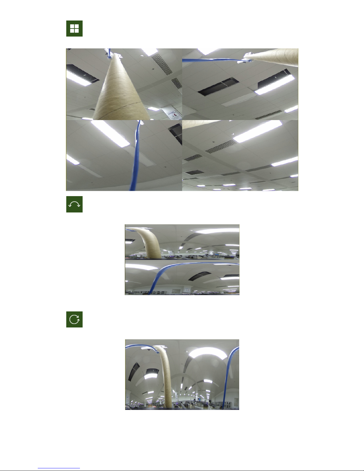
7.1.3 CEILING INSTALLATION
The fisheye camera is mounted on the ceiling on the scene. There are 12 display modes, as shown in the figure:
DS1093-582
14

1) VR view, double click with the right mouse button to begin navigation;
2) 3D Cylinder, as shown in the figure:
3) 2PTZ, as shown in the figure:
DS1093-582
15

4) 4PTZ, as shown in the figure
5) 180° Panorama view, as shown in the figure:
6) 360° Panorama view, as shown in the figure:
7) 360° Panorama View + 1PTZ (Panorama View, the different coloured area represents different PTZ viewing
angles, select the range of the corresponding PTZ line and drag to change the viewing angle, as shown in the figure):
DS1093-582
16

8) 360° Panorama View + 3PTZ (Panorama View, the different coloured areas represent different PTZ viewing
angles, select the range of the corresponding PTZ line and drag to change the viewing angle, as shown in the figure):
9) 360° Panorama View + 6PTZ (Panorama View, the different coloured areas represent different PTZ viewing
angles, select the range of the corresponding PTZ line and drag to change the viewing angle, as shown in the figure):
DS1093-582
17

10) 360° Panorama View + 8PTZ (Panorama View, the different coloured areas represent different PTZ viewing
angles, select the range of the corresponding PTZ line and drag to change the viewing angle, as shown in the figure):
11) Fisheye + 3PTZ (Fisheye View, the different coloured areas represent different PTZ viewing angles, select the
range of the corresponding PTZ line and drag to change the viewing angle, as shown in the figure):
DS1093-582
18

12) Fisheye + 8PTZ (Fisheye View, the different coloured areas represent different PTZ viewing angles, select the
range of the corresponding PTZ line and drag to change the viewing angle, as shown in the figure):
DS1093-582
19

7.1.4 WALL INSTALLATION
The fisheye camera is mounted on the ceiling on the scene. There are 7 display modes, as shown in the figure:
1) VR view, double click with the right mouse button to begin navigation;
DS1093-582
20

2) Standard Panorama view, as shown in the figure:
3) 4PTZ
4) Panorama View + 3PTZ (Panorama View, the different coloured areas represent different PTZ viewing angles,
select the range of the corresponding PTZ line and drag to change the viewing angle, as shown in the figure):
DS1093-582
21

5) Panorama View + 8PTZ (Panorama View, the different coloured areas represent different PTZ viewing angles,
select the range of the corresponding PTZ line and drag to change the viewing angle, as shown in the figure):
6) Fisheye + 3PTZ (Fisheye View, the different coloured areas represent different PTZ viewing angles, select the
range of the corresponding PTZ line and drag to change the viewing angle, as shown in the figure):
DS1093-582
22

7) Fisheye + 8PTZ (Fisheye View, the different coloured areas represent different PTZ viewing angles, select the
range of the corresponding PTZ line and drag to change the viewing angle, as shown in the figure):
7.1.5 INSTALLATION ON A HORIZONTAL SURFACE
The fisheye camera is mounted on a horizontal surface/table, there are 11 viewing modes, as shown in the figure
DS1093-582
23

1) VR view, double click with the right mouse button to begin navigation;
2) 3D Cylinder view, as shown in the figure:
DS1093-582
24
3) 4PTZ, as shown in the figure:
4) 180° Panorama view, as shown in the figure:
5) 360° Panorama view, as shown in the figure:
DS1093-582
25

6) 360° Panorama View + 1PTZ (Panorama View, the different coloured area represents different PTZ viewing
angles, select the range of the corresponding PTZ line and drag to change the viewing angle, as shown in the figure):
7) 360° Panorama View + 3PTZ (Panorama View, the different coloured area represents different PTZ viewing
angles, select the range of the corresponding PTZ line and drag to change the viewing angle, as shown in the figure):
DS1093-582
26

8) 360° Panorama View + 6PTZ (Panorama View, the different coloured area represents different PTZ viewing
angles, select the range of the corresponding PTZ line and drag to change the viewing angle, as shown in the figure):
9) 360° Panorama View + 8PTZ (Panorama View, the different coloured area represents different PTZ viewing
angles, select the range of the corresponding PTZ line and drag to change the viewing angle, as shown in the figure):
DS1093-582
27

10) Fisheye + 3PTZ (Fisheye View, the different coloured areas represent different PTZ viewing angles, select the
range of the corresponding PTZ line and drag to change the viewing angle, as shown in the figure):
11) Fisheye + 8PTZ (Fisheye View, the different coloured areas represent different PTZ viewing angles, select the
range of the corresponding PTZ line and drag to change the viewing angle, as shown in the figure):
DS1093-582
28

7.1.6 INSTALLATION ON AN INCLINED PLANE
The fisheye camera is installed on the scene which is about 25° from the vertical. There are 7 display modes, as shown
in the figure:
1) VR view, double click with the right mouse button to begin navigation;
DS1093-582
29

2) Standard Panorama view, as shown in the figure:
3) 4PTZ and Panorama View + 3PTZ (Panorama View, the different coloured areas represent different
PTZ viewing angles, select the range of the corresponding PTZ line and drag to change the viewing angle, as shown in
the figure):
DS1093-582
30

4) Panorama View + 8PTZ (Panorama View, the different coloured areas represent different PTZ viewing angles,
select the range of the corresponding PTZ line and drag to change the viewing angle, as shown in the figure):
5) Fisheye + 3PTZ (Fisheye View, the different coloured areas represent different PTZ viewing angles, select the
range of the corresponding PTZ line and drag to change the viewing angle, as shown in the figure):
DS1093-582
31

6) Fisheye + 8PTZ (Fisheye View, the different coloured areas represent different PTZ viewing angles, select the
range of the corresponding PTZ line and drag to change the viewing angle, as shown in the figure):
DS1093-582
32

8 LOCAL SETTINGS
Select Local Settings to display the following dialogue box: in it you can set the video storage location, paths for
downloading the remote file and store the snapshot, the file type (RF by default, with H265, AVI, MP4 or BMP encoding),
video recording duration and capture type (BMP or JPG).
DS1093-582
33

9 PLAYBACK
Select Playback in Record File, select the corresponding date, then click Search to go to the page here below
Explanation of the button functions:
Type of recording file: ALL, Normal, IO.
Normal: 24H recording
(IO) alarms: Motion and Alarms.
: from left to right, play/pause, stop, Advance by one frame,
(select once to play a frame), Record, Capture, Download, zoom, audio control.
: from left to right, zoom, original proportions, increase scale, full screen.
For devices that are enabled for video recording, playback also supports the fisheye software features available in the Live
section
DS1093-582
34

10 REMOTE SETTING
10.1 DISPLAY CONFIGURATION
10.1.1 LIVE
Select Remote Settings to open the page shown below (default preview setting page):
Name: Name of the IP camera.
Flicker control: Choose 50Hz or 60Hz.
Transparency: choose the display transparency of the channel name and time on the preview frame (the lower the value,
the higher the transparency).
Show Name: the camera name is displayed.
Show Time: the date and time are displayed.
OSD: the text in red on the frame; the channel name and time display can be localised by dragging it in the preview frame.
35
DS1093-582

10.1.2 IMAGE CONTROL
Select Image Control in Display to open the following page:
IR-CUT Mode: GPIO Automatic, Colored and Black-White.
IR-CUT Delay: IR-cut switching delay.
Lens Flip: On/Off,
Angle Flip: On/Off,
Corridor Mode: On/Off,
Angle Rotation: 0° or 180°,
Back Light: On/Off,
3D Noise Reduction: Off, Automatic, Manual.
Level: 0 to 255.
WDR: On/Off,
AGC: OFF, Low, Medium, High.
White Balance: Automatic, Manual, Internal.
Shutter: Automatic, Manual
Defog Mode: Off, Automatic, Manual.
DS1093-582
36

10.1.3 PRIVACY ZONE
Select Privacy Zone in Display Configuration to open the following page:
Enable Privacy Zone, and then use the right mouse button to trace rectangles around areas not to be displayed during recording,
in screenshots and in Live viewing.
Save when done to keep the settings.
10.1.4 ROI
Select Display to open the following page:
ROI setting procedure:
1. Choose a region of application,
2. Press and hold the left mouse button and drag out a ROI (only one ROI can be set for each zone),
3. Select Save to apply the ROI zone.
• Region ID: Up to 8 ROIs can be set in one bit stream.
DS1093-582
37

• Enable Region: Enable or disable the ROI.
• ROI level: Select a bit stream for the ROI from worst (), worse (), bad (), normal (), better () and best ().
• Non-ROI frame rate Fps: Set the frame rate outside of the ROI; the smaller the value, the higher the image quality in the
ROI. The frame rate range depends on the video standard and the resolution. It varies from 1 to 25 Fps. (Note: Different non-
ROI frame rates may be given to different ROIs, but the lowest value among them will be used as the frame rate applied to
the non-ROI zone on the preview frame.)
10.2 RECORD PARAMETERS
10.2.1 REC PARAMETERS
Select Rec Parameters in the menu Record to access the page below
This function allows you to control recording, pre-recording and type of recording (main stream and substream).
DS1093-582
38

10.2.2 SCHEDULE
Select Schedule in the menu Record to access the page below.
Example: one grid in the table is equal to 30 minutes, green means normal recording, yellow means motion detection
alarm, red means an alarm recording. You can set these parameters, according to your needs, to choose different types or
times of recording.
10.3 NETWORK
10.3.1 NETWORK
Select Network to open the following page:
DS1093-582
39

Type: Network connection mode: DHCP (Automatically Acquired), Static (Manual Configuration) and PPPOE; DHCP
(Automatically Acquired) is the default setting.
Client Port: The port for the clients that connect to the IP camera.
HTTP Port: Web port for the IP camera.
IP address: The IP address of the IP camera.
Subnet mask: The subnet mask of the IP camera.
Gateway: The default gateway of the device.
DNS 1: Sets the primary DNS server.
DNS 2: Sets the secondary DNS server.
UPNP: Enables or disables the UPNP function for the device (enabled by default).
Note: To enable the UPNP function, the client port must be set between 1024 and 65535; the client port is used to connect
with a cell phone or other devices.
10.3.2 VIDEO STREAMING
Select Video Streaming Setting in the Network menu to open the following page:
The following bit streams are available by default: Main bit stream, Sub stream (secondary bit stream) and Mobile
stream (cell phone bit stream).
You can set the resolution, frequency, video encoding, encoding level, bitrate control, bitrate mode, bitrate frequency,
audio, single frame interval, respectively, for the main bit stream , the secondary bit stream and the mobile stream.
Resolution: Sets the resolutions for the respective bit streams: The maximum resolution for the main bit stream is
1098x1080. The maximum resolution for the secondary bit stream is 746x576. The resolutions for mobile devices are
640x480, 320×480.
FPS: When the refresh rate is 50Hz, the maximum available FPS is 25 fps. When the refresh rate is 60Hz, the maximum
available FPS is 30 fps.
Video Code Type: Sets the video encoding (H265/H264) for each bit stream.
Video Code Level:
Bitrate control: Set constant or variable bitrate for the stream.
(Bitrate mode): User-defined or Predefined.
Note: The range of the main bit stream is 256-8192.
The range of the substream is 128-4096.
DS1093-582
40

The range of the mobile bit steam is 8-1536.
Audio: Enables audio for each bit stream.
I frame interval: Sets the interval of a single frame.
10.3.3 E-MAIL CONFIGURATION
Select E-Mail in the Network menu to open the following e-mail service setup page - used with the alarm function to send
images to the mail server:
E-Mail: Service enabling/disabling.
Encryption: The options are Deactivate/SSL/TLS/AUTO.
SMTP Port: The default port number is 25.
SMTP server: Enter the address of the mail server.
User Name: Username of the e-mail sender.
Password: Password of the sending mailbox.
Sender: Address of sending mailbox.
Receiver1: Address of first receiver mailbox.
Receiver2: Address of second receiver mailbox.
Receiver3 Address of third receiver mailbox.
Interval: Time interval for sending e-mail (1 minute, 3 minutes, 5 minutes, 10 minutes).
Test E-mail: Select it to test whether the mailbox is configured properly by sending a test e-mail to the receiver
mailbox.
The Refresh, Save and Cancel buttons are features provided to update the page, save it or delete the data entered.
DS1093-582
41

10.3.4 DDNS CONFIGURATION
Select DDNS in the Network menu to open the following page:
DDNS: Dynamic DNS configuration – used with the server to access an Extranet network.
DDNS (Dynamic DNS) is a service used to record a domain name and floating IP address with the DDNS server so that
the domain name can be routed towards the IP address even if it is modified in a dynamic IP system.
DDNS: Enable or disable the function.
Server: Server options are 3322/DynDNS/NO-IP. Choose the Server address.
Hostname: Enter the name of the active server.
User Name: Name of the user.
Password: User’s password
DS1093-582
42

10.3.5 IP FILTER
Select IP Filter in the Network menu to open the following page:
• Filtering mode: Three modes are available (Allow all IP connections, Allow only IP connections which have been
set up, Do not Allow the IP connections which have been set up).
• Add: Add a permitted or prohibited IP address.
• Delete: Delete an IP address added previously.
• Refresh: update the values.
• Save: save the set values.
10.3.6 RTSP
Select RTSP in the Network menu to open the following page:
• RTSPEnable Enable or disable RTSP. RTSP is enabled by default. After it is disabled, it will not be found with
ONVIF.
• RTSP Port: The default port number is 554 and it can be changed by setting another value between 1024 and
65535. Changing this parameter will restart the system.
DS1093-582
43

Operating instructions:
rtsp://IP:Port/ch01/A A:0(Main Stream), 1(Sub Stream), 2(Stream Mobile):
10.3.7 FTP
FTP: FTP service setting - used with alarm function to upload images or videos to the FTP server.
Select FTP in the Network menu to open the following page:
FTP Enable: Enable or disable the FTP function.
Server: Enters the address of the FTP server.
Port: FTP service port number; the default number is 21.
Username: The username for access to the FTP service.
Password: The password for access to the FTP service.
Transfer images: Select to enable the transmission of images.
DS1093-582
44

10.4 ALARM
10.4.1 MOTION
Select Motion in the Alarm menu to open the following page:
Motion detection setting procedure:
1. Select Enable
2. Click and hold the left mouse button and drag out an area for motion detection.
3. Set the motion detection sensitivity (from 1 to 8; the higher the value, the greater the sensitivity).
4. Enable Alarm Output, Latch Time (recording time) and Post recoding time.
5. Enable Send Mail, a function used with SMTP to enable the sending of e-mail.
6. Select Save to apply the settings.
(Note: When any object moves within the target area, a green letter "M" is displayed in the preview frame)
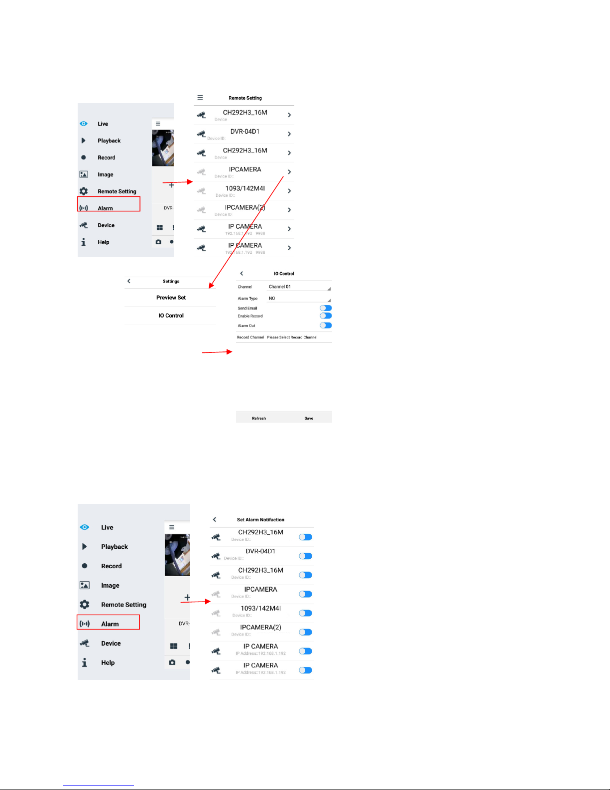
10.4.2 I/O ALARM:
Select Alarm in the Alarm menu to open the following page:
Alarm Type: Available values: OFF, Normally-Open, Normally-Closed.
Latch Time: Set the alarm output time (5s,10s, 20s, 30s).
Send E-mail, Alarm Output, Enable Recording.
Post Recording: After ticking Enable Record, you can set the recording delay (5s,10s, 20s, 30s).
DS1093-582
45

10.4.3 LENS BLOCKING
Select Occlusion Detection in the Alarm menu to open the following page:
Select Enable to activate the Sensitivity and Send E-mail options.
Sensitivity: Set the sensitivity level (level 1~6; the higher the value, the greater the sensitivity level).
Send E mail: When enabled, it can be used with SMTP to enable the sending of e-mail.
Mail Linkage: This is disabled by default. When enabled, it can be used with SMTP to enable the e-mail address.
DS1093-582
46

10.5 DEVICE
This includes SD Card, Logs and Audio. The various interfaces and functions are described below.
10.5.1 HDD (WHERE INCLUDED)
Select HDD in the Device menu to access the page below.
Insert SD card in device, system will auto detect the total capacity and provide information on the remaining recording
time.
Overwrite: when the capacity of SD card is 0, new records will overlap previous records (this function is on by default).
HD Format: Formats the SD card.
10.5.2 AUDIO
Click on Audio in the Device menu to open the following page:
Audio setup procedure:
Check the Enable Audio option to access audio settings, and set the audio input/output volume (range 0~10), and then
select Save to save the parameters set. (Note: To be able to use the audio function, the audio option in Video Streaming
needs to be enabled).
DS1093-582
47

10.5.3 LOGS
Click on Logs in the Device menu to open the following page:
Log Type: Eight log types are available: System Log, Config Log, Alarm Log, User Log, Record Log, Storage Log
Network Log, and all Log with their respective Minor Types, defined for the various types of Log.
Choose a starting and ending date/time.
Select "Search" to search and view the related Logs.
DS1093-582
48

10.6 SYSTEM
System parameters include: General, Users and Information. The various interfaces and functions are described below.
10.6.1 GENERAL
Click on General in the System menu to open the following page:
The device time, system time and date/time format contained in the basic information can be manually set and saved.
Three automatic time setting functions are provided in this device.
DST: Check the Daylight Savings Time (DST) option to enable DST correction.
The device will correct the time based on the set time difference.
NTP: Check the Enable NTP option, input the address of the time server and choose a time zone and then save the
setting. The system will correct the time based on the synchronisation server.
Syncronize: The device will use the PC as a synchronisation server to correct the time.
DS1093-582
49

10.6.2 USER CONFIGURATION
Click on User in the System menu to open the following page:
In this section you can set the user access authority and login password.
10.6.3 SYSTEM INFO
Select Info in the System menu to open the following page:
In this section some system information on the device will be displayed, including device type, MAC address and software
version.
The QR Code is a P2P ID that can be used by an app.
DS1093-582
50

10.7 ADVANCED SETTINGS
They include Firmware Update, Load Default and Maintain, System Update, Default Parameters and System
Maintenance. The various interfaces and functions are described below.
10.7.1 SYSTEM UPDATE
Select Firmware Update in the Advanced menu to open the following page:
The update will not be available if the files are not compatible with the target device.
10.7.1 LOAD DEFAULT:
Select Load Default in the Advanced menu to open the following page:
Tick the relevant options and select Save to restore the default factory settings.
10.7.2 SYSTEM MAINTENANCE
Select Maintain in the Advanced menu to open the following page:
DS1093-582
51

11 SOFTWARE FOR MOBILE DEVICES
Mobile Software is used for the iOS (iPhone, iPad) and Android platforms (Android Smartphone, Tablet).
The following is a description of the Mobile Client Software.
11.1 Smartphone Device
11.1.1 URMET IUVS PLUS MOBILE SOFTWARE
Urmet iUVS plus is a TVCC application for iOS and Android on smartphones, pads and tablets that is compatible with all
URMET devices, both IPCam (Codec H265) and DVR/NVR/HVR (all codecs).
Main features:
• Multichannel audio/video live streaming
• Multichannel remote playback
• Double stream playback
• Fisheye Camera support in Live and Playback modes
• Alarm notifications
• Custom single video stream configuration
• Video signal format management 4:3 – 16:9
• Local playback
• Video signal in portrait or landscape mode
• Device list export function
• Image sharing on social media/remote drives and personal clouds
• PTZ:
• Image and Video capture
• Multi-device support
Getting Started
• Download the iUVS app from the Apple Store or Google Play Store and install it.
• Connect your iPhone, iPad, Android phone or Android tablet to the Internet via the 3G network or WIFI.
• Launch the application to access the "Live" menu
To access the menu, select the icon in the top left corner
DS1093-582
52

11.1.1.1 Live
From inside the menu select “Live” to bring up the Live interface, which provides video streaming, recording, snapshot and
PTZ, etc.
1. Open a device
Select to open the device list shown below, then select one of devices in the list, this will open all its channels
automatically.
DS1093-582
53

11.1.1.1.1 Opening a channel
Select a device, the list of channels will be displayed, select a channel, which will be displayed in the main window.
11.1.1.1.2 Recording a live video stream
You can record the stream while viewing a video in live mode. Select and then the channel label to start
recording. Recording will continue in the live page once it has started; only the channels that are being displayed can be
recorded. Recording stops if you close the channel or exit the live page.
Live video In live mode, selecting allows to select channels individually or all together.
54
DS1093-582

11.1.1.1.3 PTZ Control
PTZ is short for Pan-Tilt-Zoom and refers to camera movement options. Select to open the PTZ mode, it will bring
up the PTZ buttons to control the live page PTZ.
Select the arrows to move it sideways or up and down. The other keys can be used to control the zoom, force, operate the
aperture, preset, etc.
11.1.1.2 Playback
In the main menu select "Playback"; the play list will be displayed.
It will be possible to remotely play a channel of the device.
DS1093-582
55

1. Selecting a channel
Select the “Remote Playback” button to open the device list, as shown below; select a channel on a device in the list.
2. Selecting the date
When you have selected a channel, all dates with recordings will be marked with a dot. Select a date to play the
recordings from that day.
DS1093-582
56

11.1.1.3 Record
You can record the stream while viewing a video in live mode, as described previously.
11.1.1.4 Images
Images opens a gallery of screenshot pictures.
DS1093-582
57
11.1.1.5 Remote Settings
Controls on the remote device can be enabled, such as sending e-mail and enabling recording on the device.
11.1.1.6 Alarm
E-mail notification of the devices can be enabled.
DS1093-582
58

11.1.1.7 Device
Add or delete a device
“Device” can be used to add or delete a device, and also edit device properties.
Select Menu and “Device” or the icon in the top right corner of the start screen to open the interface
shown below and manually add a device
To add a new device, select “+”, then Manual Adding, Import Device (via QR Code), Online Device (Devices present on
network): enter the name of the device, the address (IP, domain name or device ID for the DDNS Urmet account), the
port, user name and password, etc. The channel properties can be obtained from the device.
DS1093-582
59

To add a device using automatic network search:
Choose the device and select “Add Device”
NOTE: the Data Port (i.e. 9000) must be set up in order for the iUVS Mobile Software to work properly. If you do
not configure the mobile device port, the iUVS Mobile Software will not work.
To delete a device from list, select the name of the device that you want to delete, then press the delete button next to the
device name.
11.1.1.8 Help
This is a guide with information on the various items in the menus.
DS1093-582
60

11.2 P2P FUNCTION
In order to remotely display images on an iPhone or Android smartphone, configure the IP Camera in the network and
download the URMET iUVS application from their respective stores.
In order to display images on Apple iPad or an Android tablet, upload the iUVSpad app from the Apple Store or iUVStab
app from Play Store - respectively.
After the application has been downloaded from the store and installed, the IP Camera can be added and viewed on a
smartphone via a P2P connection as follows:
1.
Launch the “iUVS” app and select “Devices” and then “Add”
Fill in the “Device name” field.
Select the symbol to enter the
IP Camera ID - reading it from the
QR code. Install the QR code
reader app on your smartphone if
you did not have it, then scan the
QR code on the IP Camera.
DS1093-582
61

Fill in the “Password” field
by entering the NVR
password (default:
00000000) then select
“Save” and wait about 10
seconds for the NVR LIVE
video to be automatically
uploaded.
IMPORTANT:
o In addition to P2P mode, the IP camera can also be remotely viewed on a smartphone via the Urmet DDNS
service. To do this, the router must be set for port opening and forwarding.
o To view the IP camera in the local network (LAN), it can be added to the app using its IP address. In order to
know the IP Camera local IP address see the menu page [Network Menu] of the IP Camera.
DS1093-582
62

12 FISHEYE IP CAMERAS TECHNICAL SPECIFICATIONS
Description
UFO 4K
UFO 5M
Canister 5M
1093/185FE
1093/186BN
109
3/187C
G/N change mode
IR cut filter with auto switch
Max Resolution
9MP (3000X3000)
5MP (2160 x 2160)
Mainstream
Items
Camera
Standard
Compression
Image Sensor 1/1.7" Progressive CMOS
Sensor Type IMX274 IMX326
Video Format Optional format P/N
Color 0.01lux @
Minimum Luminance
Lens Mount/Lens Type Fish Eye
Viewing angle H.FOV: 360°
Shutter Speed 1/5 ~ 1/20000s
Shutter Slowdown Supported
Wide Dynamic Range Digital WDR
Digital noise reduction 3D DNR
IR illuminator range 3 LEDs (SMD) / up to 5m
Standard Video Compression H. 265 (Main profile)/ H.264
Video Compression Rate 64Kbps~ 16Mbps 64Kbps~ 8Mbps
F1.2(AGC ON)
B/W 0 lux @ IR ON
1/2.9" Progressive CMOS
Color 0.1lux @ F1.2(AGC ON)
B/W 0 lux @ IR ON
Mainstream
(1-30fps optional)
3000x3000, 2560x2560,
2160x2160, 1520x1520,
1080x1080, 720x720
Picture
Users No.: Max Stream/PC access 10
Software
Functions
Frame Rate
Image settings
Email Alarm
FTP
RTSP
P2P
NTP, DST, Sync. with PC time
Substream
(1-30fps optional)
1080x1080, 720x720,
480x180, 240x240
Mobilestream
(1-30fps optional)
480x480, 240x240
Rotation, Saturation, Brightness, Contrast, Sharpness,
settings can be adjusted via Client Software or Web Browser
Picture or video upload to FTP Server
Mainstream
(1-30fps optional)
2160x2160,1520x1520,
1080x1080, 720x720
Substream
(1-30fps optional)
720x720,480x480
240x240
Mobilestream
(1-30fps optional)
480x480, 240x240
YES
YES
YES
YES
(1-30fps optional)
2160×2160,1520x15
20,1080x1080,720x
720
Substream
(1-30fps optional)
720x720,480x480
240x240
Mobilestream
(1-30fps optional)
480x480, 240x240
DS1093-582
63

Items
Description
UFO 4K
UFO 5M
Canister 5M
1093/185FE
1093/186BN
109
3/187C
Dimensions
Φ 120x55mm
Φ 68x77mm
SMART
capability
Network
Interface
ROI
YES
Multi-Browser support:
Internet Explorer 11.0 for Windows 7 and higher/ Firefox Mozilla up to v.51/
Web/Client/ Mobile
Urmet UVS Client Support:
Safari 6.0
Windows 7 O.S. or higher / MAC O.S. 10.8.0 or higher
Mobile Support Software: (iOS, Android)
Intelligent Video Analysis NO
Protocols
TCP/IP,HTTP,DHCP,DNS,DDNS,RTP/RTSP,PPPoE,
SMTP,NTP,UPnP,SNMP,HTTPS,FTP
Memory SD card, NVR NO
Communication interface 1 RJ45 10M / 100M Ethernet interface
System compatibility ONVIF (Ver 2.6)
Security
Flash, three video streams, mirror, password protection, privacy mask,
IP filter
Alarm trigger Yes (1 input, 1 output) NO
Audio Yes (1 audio input) NO
Protective connector Waterproof RJ45 connector
Protection Rating IP64
Reset button YES NO
SD Card Supports up to 128 GB (not included in supply) NO
Video Output YES NO
PoE YES
Operating conditions
Power supply 12 VDC ± 10%, PoE (802.3af)
General
Specifications
Power Consumption
Weight(g) 400 256
-30~+60° C -30 °C ~ 55 °C (-22°F ~131°F)
Humidity 95% or less (non-condensing)
Day: Max 5W
Night: Max 7.2W
Day: Max 2.7W
Night: Max 6.7W
Day: Max 2.8W
Night: Max 7.4W
DS1093-582
64

13 MAXIMUM RECORDING TIME WITH SD CARD
Bitrate
Frame rate
SD 8GB
SD 8GB
SD 16GB
SD 16GB
SD 32GB
SD 32GB
SD 64GB
SD 64GB
SD 128GB
SD 128GB
Bitrate
Frame rate
SD 8GB
SD 8GB
SD 16GB
SD 16GB
SD 32GB
SD 32GB
SD 64GB
SD 64GB
SD 128GB
SD 128GB
Bitrate
Frame rate
SD 8GB
SD 8GB
SD 16GB
SD 16GB
SD 32GB
SD 32GB
SD 64GB
SD 64GB
SD 128GB
SD 128GB
13.1 REF. 1093/185FE– REF. 1093/186BN
The following resolution options can be selected for Main Stream recording:
“9Mpx”, “6.5Mpx”, “5Mpx”, “3Mpx”, “1080P”, “720P” for IP camera with coding H.265
“9Mpx”, “6.5Mpx”, “5Mpx”, “3Mpx”, “1080P”, “720P” for IP camera with coding H.264
IMPORTANT NOTES
Bandwidth and SD card duration can vary greatly, depending on the scene being recorded.
The following tables show the approximate time needed to fill the SD Card when the IP channel records video
only (i.e. no audio) at the resolution and frame rate selected.
1 recording channel with 9Mpx resolution (3000x3000) with H.265 coding
Variables to be set Results Results Results Results Results
(Kbps)
8192 24-25 0.13 0.01 2.25 0.09 6.49 0.27 14.96 0.62 31.92 1.33
7168 20-23 0.15 0.01 2.57 0.11 7.41 0.31 17.10 0.71 36.48 1.52
6144 16-19 0.17 0.01 3.00 0.12 8.65 0.36 19.95 0.83 42.56 1.77
5120 12-15 0.21 0.01 4.11 0.17 10.38 0.43 23.94 1.00 51.07 2.13
4096 9-11 0.26 0,.01 4.49 0.19 12.97 0.54 29.93 1.25 63.83 2.66
3328 6-8 0.32 0.01 5.53 0.23 15.97 0.67 36.83 1.53 78.57 3.27
2560 4-5 0.41 0.02 7.19 0.30 20.76 0.86 47.88 2.00 102.14 4.26
2048 1-3 0.51 0.02 8.99 0.37 25.94 1.08 59.85 2.49 127.67 5.32
(fps)
(hours)
(days)
(hours)
(days)
(hours)
(days)
(hours)
(days)
(hours)
1 recording channel with 6.5Mpx resolution (2560x2560) with H.265 coding
Variables to be set Results Results Results Results Results
(Kbps)
8192 24-25 0.13 0.01 2.25 0.09 6.49 0.27 14.96 0.62 31.92 1.33
7168 20-23 0.15 0.01 2.57 0.11 7.41 0.31 17.10 0.71 36.48 1.52
6144 16-19 0.17 0.01 3.00 0.12 8.65 0.36 19.95 0.83 42.56 1.77
5120 12-15 0.21 0.01 4.11 0.17 10.38 0.43 23.94 1.00 51.07 2.13
3840 9-11 0.27 0.01 4.71 0.20 13.60 0.57 31.36 1.31 68.09 2.84
3072 6-8 0.34 0.01 5.99 0.25 17.30 0.72 39.90 1.66 85.11 3.55
2560 4-5 0.41 0.02 7.19 0.30 20.76 0.86 47.88 2.00 102.14 4.26
1792 1-3 0.59 0.02 10.27 0.43 29.65 1.24 68.40 2.85 145.91 6.08
(fps)
(hours)
(days)
(hours)
(days)
(hours)
(days)
(hours)
(days)
(hours)
1 recording channel with 5Mpx resolution (2160x2160) with H.265 coding
Variables to be set Results Results Results Results Results
(days)
(days)
(Kbps)
7168 24-25 0.15 0.01 2.57 0.11 7.41 0.31 17.10 0.71 36.48 1.52
6144 20-23 0.17 0.01 3.00 0.12 8.65 0.36 19.95 0.83 42.56 1.77
5120 16-19 0.21 0.01 4.11 0.17 10.38 0.43 23.94 1.00 51.07 2.13
4096 12-15 0.26 0,.01 4.49 0.19 12.97 0.54 29.93 1.25 63.83 2.66
3328 9-11 0.32 0.01 5.53 0.23 15.97 0.67 36.83 1.53 78.57 3.27
2560 6-8 0.41 0.02 7.19 0.30 20.76 0.86 47.88 2.00 102.14 4.26
2048 4-5 0.51 0.02 8.99 0.37 25.94 1.08 59.85 2.49 127.67 5.32
1536 1-3 0.68 0.03 11.99 0.50 34.59 1.44 79.80 3.33 170.23 7.09
(fps)
(hours)
(days)
DS1093-582
(hours)
(days)
(hours)
65
(days)
(hours)
(days)
(hours)
(days)

1 recording channel with 3Mpx resolutions (1520×1520) with H.265 coding
Bitrate
Frame rate
SD 8GB
SD 8GB
SD 16GB
SD 16GB
SD 32GB
SD 32GB
SD 64GB
SD 64GB
SD 128GB
SD 128GB
Bitrate
Frame rate
SD 8GB
SD 8GB
SD 16GB
SD 16GB
SD 32GB
SD 32GB
SD 64GB
SD 64GB
SD 128GB
SD 128GB
Bitrate
Frame rate
SD 8GB
SD 8GB
SD 16GB
SD 16GB
SD 32GB
SD 32GB
SD 64GB
SD 64GB
SD 128GB
SD 128GB
Variables to be set Results Results Results Results Results
(Kbps)
(fps)
(hours)
(days)
(hours)
(days)
(hours)
(days)
(hours)
(days)
(hours)
3584 24-25 0.29 0.01 5.14 0.21 14.83 0.62 34.20 1.43 72.95 3.04
3072 20-23 0.34 0.01 5.99 0.25 17.30 0.72 39.90 1.66 85.11 3.55
2560 16-19 0.41 0.02 7.19 0.30 20.76 0.86 47.88 2.00 102.14 4.26
1792 12-15 0.59 0.02 10.27 0.43 29.65 1.24 68.40 2.85 145.91 6.08
1536 9-11 0.68 0.03 11.99 0.50 34.59 1.44 79.80 3.33 170.23 7.09
1280 6-8 0.82 0.03 17.98 0.75 41.51 1.73 95.76 3.99 204.27 8.51
768 4-5 1.37 0.06 23.97 1.00 69.18 2.88 159.61 6.65 340.45 14.19
512 1-3 2.05 0.09 35.96 1.50 103.78 4.32 239.41 9.98 510.68 21.28
1 recording channel with 1080P resolution (1080x1080) with H.265 coding
Variables to be set Results Results Results Results Results
(Kbps)
(fps)
(hours)
(days)
(hours)
(days)
(hours)
(days)
(hours)
(days)
(hours)
2560 24-25 0.41 0.02 7.19 0.30 20.76 0.86 47.88 2.00 102.14 4.26
2048 20-23 0.51 0.02 8.99 0.37 25.94 1.08 59.85 2.49 127.67 5.32
1664 16-19 0.63 0.03 11.06 0.46 31.93 1.33 73.66 3.07 157.13 6.55
1280 12-15 0.82 0.03 14.38 0.60 41.51 1.73 95.76 3.99 204.27 8.51
1024 9-11 1.03 0.04 17.98 0.75 51.89 2.16 119.70 4.99 255.34 10.64
768 6-8 1.37 0.06 23.97 1.00 69.18 2.88 159.61 6.65 340.45 14.19
512 4-5 2.05 0.09 35.96 1.50 103.78 4.32 239.41 9.98 510.68 21.28
384 1-3 2.73 0.11 47.95 2.00 138.37 5.77 319.21 13.30 680.90 28.37
1 recording channel with 720P resolution (720x720) with H.265 coding
Variables to be set Results Results Results Results Results
(days)
(days)
(Kbps)
(fps)
(hours)
(days)
(hours)
(days)
(hours)
(days)
(hours)
(days)
(hours)
2048 24-25 0.51 0.02 8.99 0.37 25.94 1.08 59.85 2.49 127.67 5.32
1792 20-23 0.59 0.02 10.27 0.43 29.65 1.24 68.40 2.85 145.91 6.08
1536 16-19 0.68 0.03 11.99 0.50 34.59 1.44 79.80 3.33 170.23 7.09
1280 12-15 0.82 0.03 14.38 0.60 41.51 1.73 95.76 3.99 204.27 8.51
1024 9-11 1.03 0.04 17.98 0.75 51.89 2.16 119.70 4.99 255.34 10.64
768 6-8 1.37 0.06 23.97 1.00 69.18 2.88 159.61 6.65 340.45 14.19
512 4-5 2.05 0.09 35.96 1.50 103.78 4.32 239.41 9.98 510.68 21.28
256 1-3 4.10 0.17 71.92 3.00 207.55 8.65 478.82 19.95 1021.35 42.56
(days)
DS1093-582
66

1 recording channel with 9Mpx resolution (3000x3000) with H.264 coding
Bitrate
Frame rate
SD 8GB
SD 8GB
SD 16GB
SD 16GB
SD 32GB
SD 32GB
SD 64GB
SD 64GB
SD 128GB
SD 128GB
Bitrate
Frame rate
SD 8GB
SD 8GB
SD 16GB
SD 16GB
SD 32GB
SD 32GB
SD 64GB
SD 64GB
SD 128GB
SD 128GB
Bitrate
Frame rate
SD 8GB
SD 8GB
SD 16GB
SD 16GB
SD 32GB
SD 32GB
SD 64GB
SD 64GB
SD 128GB
SD 128GB
Bitrate
Frame rate
SD 8GB
SD 8GB
SD 16
GB
SD 16GB
SD 32GB
SD 32GB
SD 64GB
SD 64GB
SD 128GB
SD 128GB
Variables to be set Results Results Results Results Results
(Kbps)
(fps)
(hours)
(days)
(hours)
(days)
(hours)
(days)
(hours)
(days)
(hours)
(days)
12288 24-25 0.09 0.00 1.50 0.06 4.32 0.18 9.98 0.42 21.28 0.89
10240 20-23 0.10 0.00 1.80 0.07 5.19 0.22 11.97 0.50 25.53 1.06
8192 16-19 0.13 0.01 2.25 0.09 6.49 0.27 14.96 0.62 31.92 1.33
7168 12-15 0.15 0.01 2.57 0.11 7.41 0.31 17.10 0.71 36.48 1.52
6144 9-11 0.17 0.01 3.00 0.12 8.65 0.36 19.95 0.83 42.56 1.77
5120 6-8 0.21 0.01 4.11 0.17 10.38 0.43 23.94 1.00 51.07 2.13
4096 4-5 0.26 0,.01 4.49 0.19 12.97 0.54 29.93 1.25 63.83 2.66
3072 1-3 0.34 0.01 5.99 0.25 17.30 0.72 39.90 1.66 85.11 3.55
1 recording channel with 6.5Mpx resolution (2560x2560) with H.264 coding
Variables to be set Results Results Results Results Results
(Kbps)
(fps)
(hours)
(days)
(hours)
(days)
(hours)
(days)
(hours)
(days)
(hours)
(days)
12288 24-25 0.09 0.00 1.50 0.06 4.32 0.18 9.98 0.42 21.28 0.89
10240 20-23 0.10 0.00 1.80 0.07 5.19 0.22 11.97 0.50 25.53 1.06
8192 16-19 0.13 0.01 2.25 0.09 6.49 0.27 14.96 0.62 31.92 1.33
7168 12-15 0.15 0.01 2.57 0.11 7.41 0.31 17.10 0.71 36.48 1.52
5376 9-11 0.20 0.01 3.42 0.14 9.88 0.41 22.80 0.95 48.64 2.03
4608 6-8 0.23 0.01 4.00 0.17 11.53 0.48 26.60 1.11 56.74 2.36
3840 4-5 0.27 0.01 4.71 0.20 13.60 0.57 31.36 1.31 68.09 2.84
2560 1-3 0.41 0.02 7.19 0.30 20.76 0.86 47.88 2.00 102.14 4.26
1 recording channel with 5Mpx resolution (2160x2160) with H.264 coding
Variables to be set Results Results Results Results Results
(Kbps)
(fps)
(hours)
(days)
(hours)
(days)
(hours)
(days)
(hours)
(days)
(hours)
10240 24-25 0.10 0.00 1.80 0.07 5.19 0.22 11.97 0.50 25.53 1.06
8192 20-23 0.13 0.01 2.25 0.09 6.49 0.27 14.96 0.62 31.92 1.33
7168 16-19 0.15 0.01 2.57 0.11 7.41 0.31 17.10 0.71 36.48 1.52
6144 12-15 0.17 0.01 3.00 0.12 8.65 0.36 19.95 0.83 42.56 1.77
5120 9-11 0.21 0.01 4.11 0.17 10.38 0.43 23.94 1.00 51.07 2.13
4096 6-8 0.26 0,.01 4.49 0.19 12.97 0.54 29.93 1.25 63.83 2.66
3072 4-5 0.34 0.01 5.99 0.25 17.30 0.72 39.90 1.66 85.11 3.55
2048 1-3 0.51 0.02 8.99 0.37 25.94 1.08 59.85 2.49 127.67 5.32
1 recording channel with 3Mpx resolutions (1520×1520) with H.264 coding
Variables to be set Results Results Results Results Results
(Kbps)
(fps)
(hours)
(days)
(hours)
(days)
(hours)
(days)
(hours)
(days)
(hours)
6144 24-25 0.17 0.01 3.00 0.12 8.65 0.36 19.95 0.83 42.56 1.77
5376 20-23 0.20 0.01 3.42 0.14 9.88 0.41 22.80 0.95 48.64 2.03
4608 16-19 0.23 0.01 4.00 0.17 11.53 0.48 26.60 1.11 56.74 2.36
3840 12-15 0.27 0.01 4.79 0.20 13.84 0.58 31.92 1.33 68.09 2.84
3072 9-11 0.34 0.01 5.99 0.25 17.30 0.72 39.90 1.66 85.11 3.55
2304 6-8 0.46 0.02 7.99 0.33 23.06 0.96 53.20 2.22 113.48 4.73
1536 4-5 0.68 0.03 11.99 0.50 34.59 1.44 79.80 3.33 170.23 7.09
768 1-3 1.37 0.06 23.97 1.00 69.18 2.88 159.61 6.65 340.45 14.19
(days)
(days)
DS1093-582
67

1 recording channel with 1080P resolution (1080x1080) with H.264 coding
Bitrate
Frame rate
SD 8GB
SD 8GB
SD 16GB
SD 16GB
SD 32GB
SD 32GB
SD 64GB
SD 64GB
SD 128GB
SD 128GB
Bitrate
Frame rate
SD 8GB
SD 8GB
SD 16GB
SD 16GB
SD 32GB
SD 32GB
SD 64GB
SD 64GB
SD 128GB
SD 128GB
Variables to be set Results Results Results Results Results
(Kbps)
(fps)
(hours)
(days)
(hours)
(days)
(hours)
(days)
(hours)
(days)
(hours)
4096 24-25 0.26 0.01 4.49 0.19 12.97 0.54 29.93 1.25 63.83 2.66
3072 20-23 0.34 0.01 5.99 0.25 17.30 0.72 39.90 1.66 85.11 3.55
2560 16-19 0.41 0.02 7.19 0.30 20.76 0.86 47.88 2.00 102.14 4.26
2048 12-15 0.51 0.02 8.99 0.37 25.94 1.08 59.85 2.49 127.67 5.32
1536 9-11 0.68 0.03 11.99 0.50 34.59 1.44 79.80 3.33 170.23 7.09
1280 6-8 0.82 0.03 14.38 0.60 41.51 1.73 95.76 3.99 204.27 8.51
1024 4-5 1.03 0.04 17.98 0.75 51.89 2.16 119.70 4.99 255.34 10.64
768 1-3 1.37 0.06 23.97 1.00 69.18 2.88 159.61 6.65 340.45 14.19
1 recording channel with 720P resolutions (720x720) with H.264 coding
Variables to be set Results Results Results Results Results
(Kbps)
(fps)
(hours)
(days)
(hours)
(days)
(hours)
(days)
(hours)
(days)
(hours)
2048 24-25 0.51 0.02 8.99 0.37 25.94 1.08 59.85 2.49 127.67 5.32
1792 20-23 0.59 0.02 10.27 0.43 29.65 1.24 68.40 2.85 145.91 6.08
1536 16-19 0.68 0.03 11.99 0.50 34.59 1.44 79.80 3.33 170.23 7.09
1280 12-15 0.82 0.03 14.38 0.60 41.51 1.73 95.76 3.99 204.27 8.51
1024 9-11 1.03 0.04 17.98 0.75 51.89 2.16 119.70 4.99 255.34 10.64
768 6-8 1.37 0.06 23.97 1.00 69.18 2.88 159.61 6.65 340.45 14.19
512 4-5 2.05 0.09 35.96 1.50 103.78 4.32 239.41 9.98 510.68 21.28
256 1-3 4.10 0.17 71.92 3.00 207.55 8.65 478.82 19.95 1021.35 42.56
(days)
(days)
DS1093-582
68

14 APPENDIX
14.1 ROUTER PORT FORWARDING
To remotely view the IP Camera via the Internet, you must first set the web port and client port of the IP Camera.
Taking a Cisco router as an example:
The IP address of the IP camera is 192.168.1.168, the web port is 8000 and the client port is 9988.
DS1093-582
69

14.2 FREQUENTLY ASKED QUESTIONS
◆ Internet Explorer cannot load and install plug-ins.
1. Possible cause: IE security levels are set too high.
Solution: Set IE security levels to the minimum value.
◆ After updating, it is not possible to access the IP Camera through Internet Explorer.
1. Solution: Clear the IE cache as follows: open IE Tools, select Internet Options, select the 2nd option under
“Delete Files” (Temporary Internet Files), click “Delete all offline content” and finally click OK. Access the camera
◆ Why am I unable to access the IP Camera through IE?
◆ The PC client cannot connect to the front-end video
◆ The mobile client cannot connect to the front-end video
again.
1. Possible cause 1: network fault.
Solution: connect the PC to the Internet and check whether network access is normal. Check that there are no
problems with cable connection or network problems so that the two devices can ping each other.
2. Possible cause 2: the IP address is occupied by other devices.
Solution: Disconnect the IP camera from the network, connect the IP camera directly to the PC and set the device
IP address.
3. Possible cause 3: the IP address belongs to a different mask.
Solution: check the settings of the IP address, the subnet mask address, and the gateway.
4. Possible cause 4: the physical address of the network conflicts with that of the IP camera.
Solution: change the physical address of the IP camera.
5. Possible cause 5: the web port has changed.
Solution: contact the network operator to obtain the port information.
1. Solution: check that the IP camera video can be normally viewed in IE, that the device can be accessed through
the client PC software and that the device parameters on the client PC are set correctly.
1. Possible cause 1: mobile stream is not enabled.
Solution: enable mobile stream.
2. Possible cause 2: the mobile port number was not entered correctly.
Solution: the mobile client software port number is 9988 and that of the third-party client is 8800.
3. Possible cause 3: the video stream connections exceed the maximum limit.
Solution: reduce the number of video stream connections on the device.
DS1093-582
70

DS1093-582
71

DS1093-582
URMET S.p.A.
10154 TURIN (ITALY)
VIA BOLOGNA 188/C
Tel. +39 011.24.00.000 (AUTO)
Fax +39 011.24.00.300 - 323
DS1093-582
72
Engineering Dept.
customer service +39 011.23.39.810
http://www.urmet.com
e-mail: info@urmet.com
MADE IN CHINA
 Loading...