

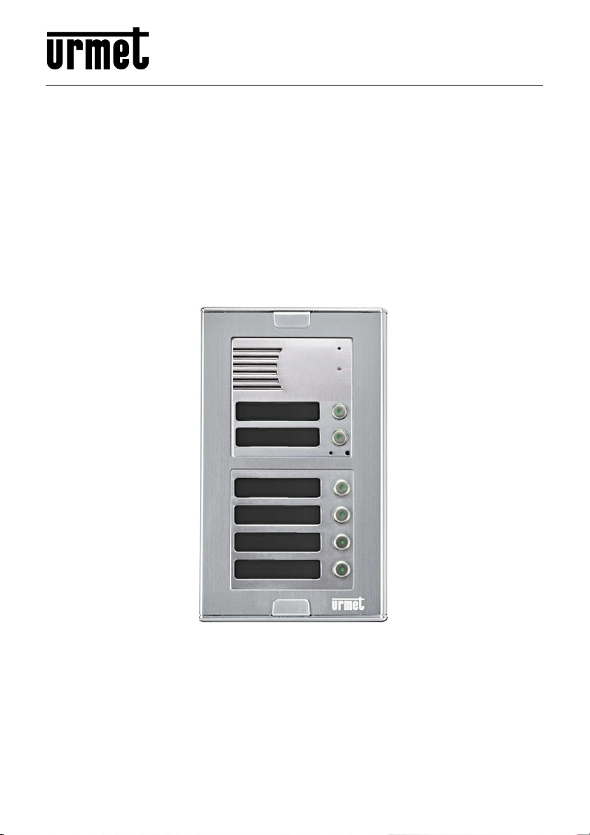
urmet domus 1148 Series, 1148/1, 1148/2, 1148/4-6-14 Installation, Programming And Functions Manual
Page 1
Mod.
DS1148-014D
UNIVERSAL COMBIPHONE DOOR UNIT
1148
Ref. 1148/1
Ref. 1148/2
Ref. 1148/4-6-14
INSTALLATION, PROGRAMMING AND FUNCTIONS MANUAL
Page 2

Table of Contents
1 BASIC FEATURES ............................................................................................. 3
2 SYSTEM MODULES .......................................................................................... 4
2.1 INSTALLATION ACCESSORIES ....................................................... 4
2.2 BASIC MODULE CONNECTION ........................................................ 6
2.3 WIRING AND FLAT CABLE CONNECTION IN DETAIL ................... 10
2.4 1148/6 KEYBOARD CONNECTION ................................................. 12
2.5 INSTALLATION OF THE DEVICES .................................................. 13
2.6 CONNECTION .................................................................................. 13
2.7 ACCESSORIES ................................................................................ 16
3 DOOR ENTRY SYSTEM OPERATION ........................................................ 17
3.1 S
3.2 C
3.3 A
4 PARAMETER PROGRAMMING ................................................................... 23
4.1 P
5 DESCRIPTION OF PROGRAMMABLE PARAMETERS .......................... 24
IGNALLING OVERVIEW
ALLER AT THE DOOR
3.2.1 Tab. 1 – Table of relay controls .............................................................. 19
3.2.2 Outbound call ......................................................................................... 20
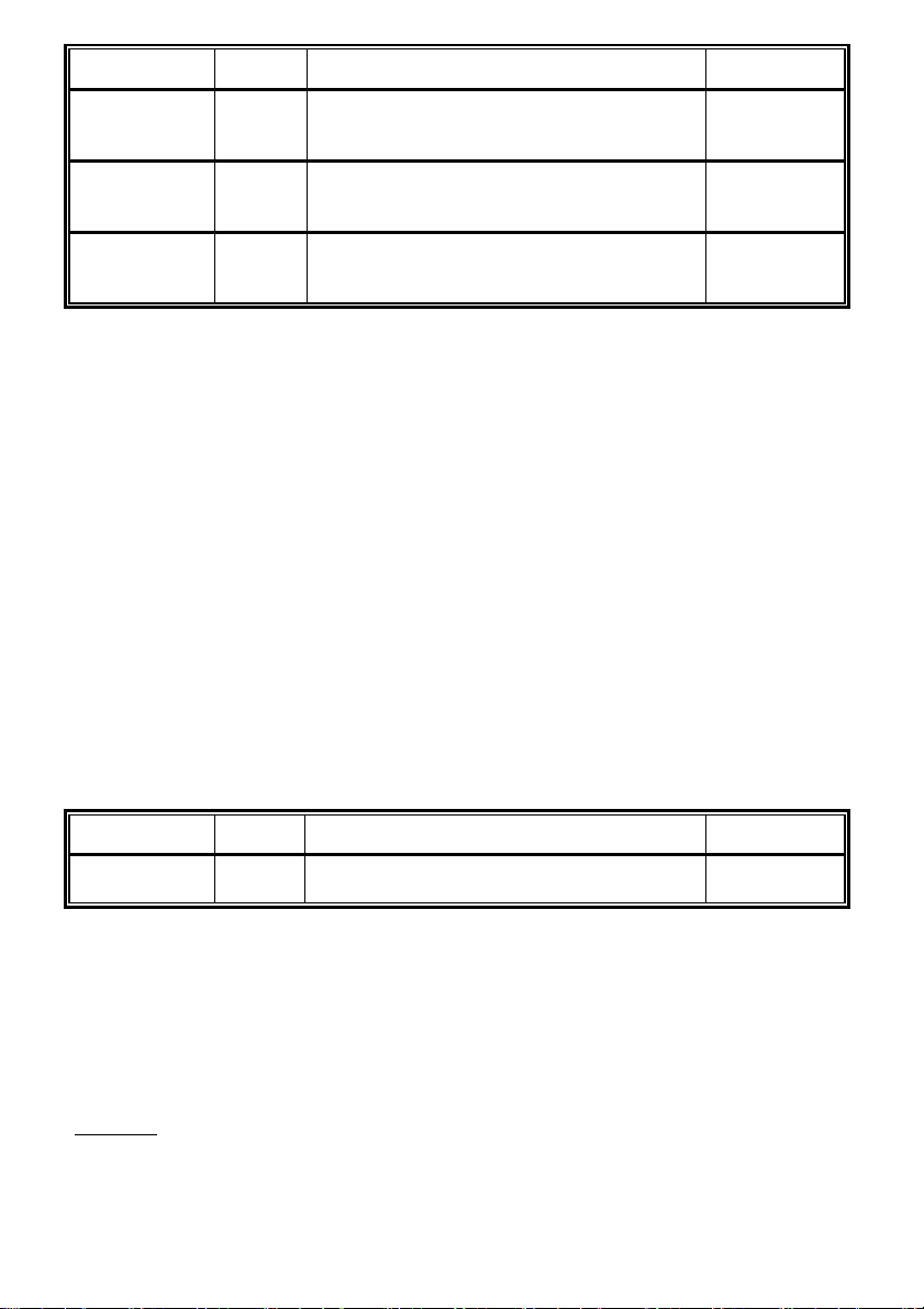
3.2.3 Incoming call .......................................................................................... 20
3.2.4 Door Entry System with keyboard – 1148/6 module ............................... 21
COUSTIC PATH SETTING
ROGRAMMING WITH THE HELP OF A PHONE
4.1.1 Entry into the programming .................................................................... 23
4.1.2 Parameter programming ........................................................................ 23
........................................................................ 17
.......................................................................... 17
..................................................................... 22
......................................... 23
5.1 D
5.2 R
5.3 B
5.4 T
5.5 S
5.6 P
5.7 B
5.8 E
5.9 P
6 TECHNICAL PARAMETERS......................................................................... 42
7 TABLE FOR EASY PROGRAMMING .......................................................... 43
8 BASIC CONNECTION DIAGRAM ................................................................ 47
2 DS1148-014D
IRECT DIALLING - MEMORY
ELAYS
.............................................................................................. 25
ASIC PARAMETERS
IME PARAMETERS
YSTEM PARAMETERS
ARAMETER SETTING HANDS FREE
ASIC SETTING AND DELETION
ND OF PROGRAMMING
ARAMETER OVERVIEW
............................................................................ 28
.............................................................................. 30
................................................................. 24
......................................................................... 33
...................................................... 35
............................................................. 38
....................................................................... 38
....................................................................... 39
Page 3

1 BASIC FEATURES
• The combiphone module Sinthesi S2 is a modular system that allows to install up to
99 buttons
• Voice communication is based on a telephone line: the module can be connected as
a PABX analogue extension or directly under an analogue telephone line
• Impulse and tone (DTMF) options
• Storage of 2 24-digit long numbers per button (including *, #, Flash and day/night
mode)
• Automatic Day/Night switch
• Option to prolong a call with * or #
• Option to activate two independent external relays through DTMF codes (with
optional power)
• Two codes to open doors from the phone for 1-impulse and two codes for 2-impulse
• Potential to use up to 8 relay modes (for an additional bell, gradual or sequential
door opening, lighting, etc.)
• Automatic answer to an incoming call with a variable number of rings
• Times control when digiting the password
• Programmable time before hanging up and make a new selection
• Programmable parameters for tone options, Flash length and Pause length
• Programmable time before starting a call
• Two codes to disconnect the call between external panel and an internal phone
• Option to program the module with a PC, the USB interface 1148/9 and remotely by
calling the module through a DTMF telephone
• Integrated regulated heating of the PCB (with optional power)
• Name tag lighting (with optional power).
• 6 code locks for each relay
• Option to connect an exit button
• Option to disconnect a call by repeating pressing the call button
• Option to switch on a mode to suppress the DTMF connection from the microphone
• Option to switch on a ‘ticking’ sound into a call to announce another call
• Option to switch on acoustic signalling for relay connection
• Option to set the number of rings before connecting a call
• Programmable parameters for acoustic signalisation
• Programmable parameters for tone detection
• Electronic volume setting without the need to open the front cover
• Easy manual setting with the help of DIP switches
• Several default level options
• Unit earthed for better protection against static electricity
DS1148-014D 3
Page 4
2 SYSTEM MODULES
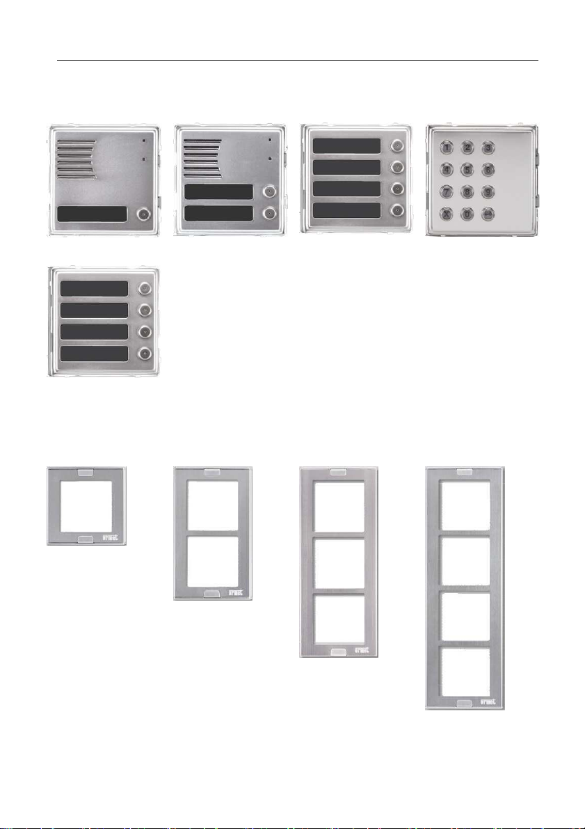
The structural components of the system are: basic modules equipped with one or two
buttons (1148/1 or 1148/2), 4-buttons modules (1148/4 and 1148/14), numeric keypad
module (1148/6).
1148/1 1148/2 1148/4 1148/6
1148/14
2.1 INSTALLATION ACCESSORIES
MODULE HOLDER WITH FRAME FOR FLUSH-MOUNTING INSTALLATION
1148/61
1148/62
1148/63
1148/64
4 DS1148-014D
Page 5
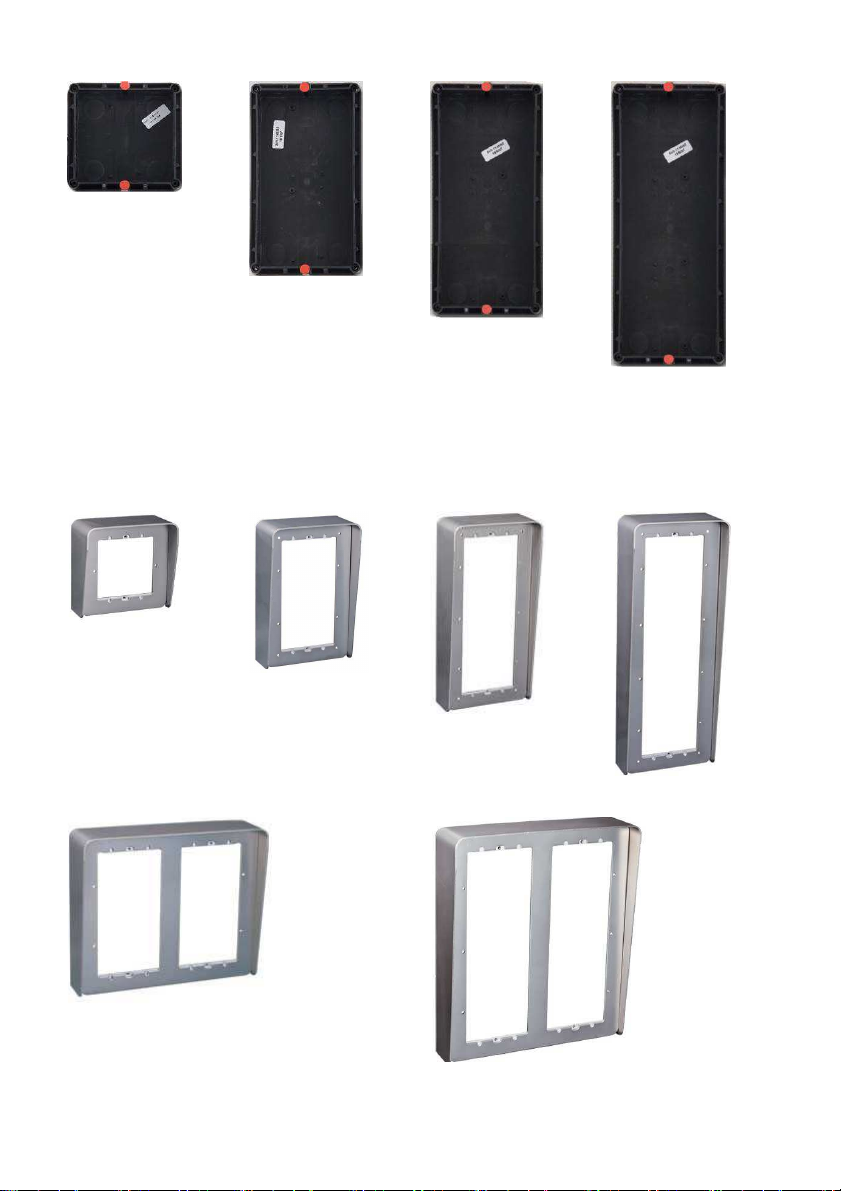
FLUSH-MOUNTING BOX
1145/51
11458/52
1145/53
1145/54
HOUSING WITH HOOD AND WALL FRAME FOR WALL INSTALLATION, TO BE
COMPLETED WITH 1148/61-62-63-64 MODULES
1148/311
1148/312
1148/313
1148/314
1148/324
1148/326
DS1148-014D 5
Page 6
RAIN HOOD FOR FLUSH-MOUNTING INSTALLATION
1158/611: for 1 module (1 row)
1158/612: for 2 modules (1 row)
1158/613: for 3 modules (1 row)
1158/614: for 4 modules (1 row)
FRAMES ASSEMBLY EXAMPLES
2.2 BASIC MODULE CONNECTION
The basic module is offered in 2 different options: with two buttons Ref.1148/2
and with one button Ref.1148/1.
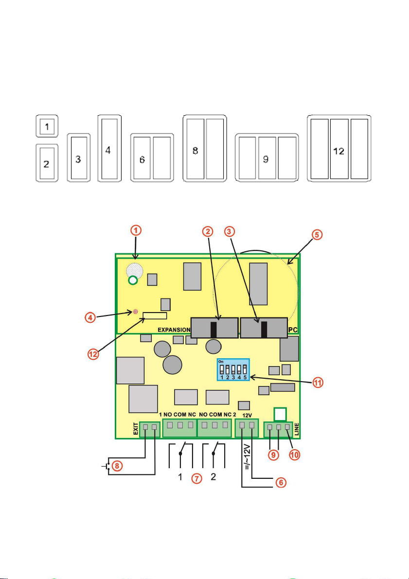
Img. 1 - Door entry system motherboard – 1148/1 and 1148/2
6 DS1148-014D
Page 7
1. Microphone (placed on the lower part of the motherboard) – be careful of the
rubber seal of the microphone when changing the name tags, as the improper
assembly may affect the acoustics.
2. Connection expansion buttons modules and keyboard
3. Connection point for a PC USB cable for PC connection.
4. LED indicator (placed on the lower part of the motherboard)
5. Speaker – at the lower part of the motherboard
6. 9000/230 power supply for:
- relay controls
- motherboard heating
- name tag back lighting
- internal power supply (DIP 3 and 4 set to ON)
- power for exit button circuit.
7. Relays – are galvanically isolated, load is max. 48V, max. 1,5A
8. Exit button - works in current loop circuit. The length of connected conductors can
be up to 500m. To work there must be the optional 9000/230 power supply
connected to the terminal (6).
9. Analogue telephone line (the polarity is not important).
10. Earth – connection for an earth against static electricity – protecting the electronics
of the door entry system and telephone system.
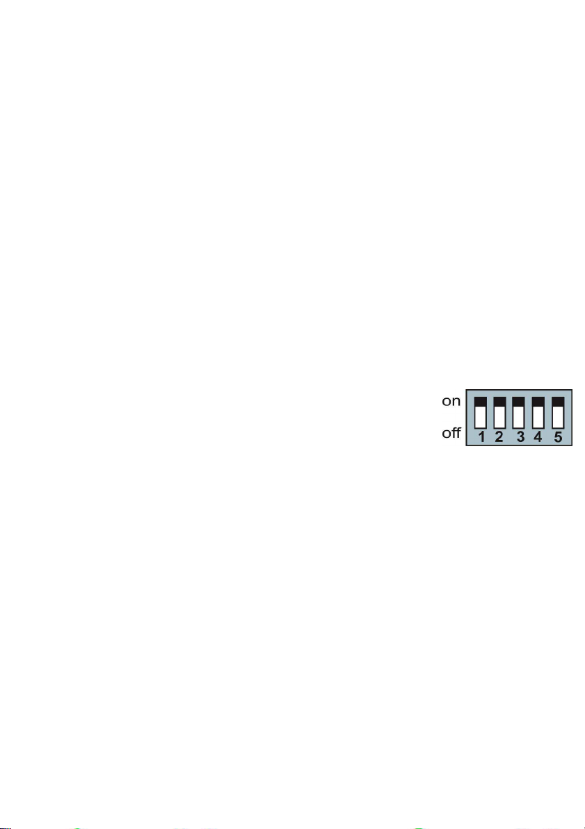
11. DIP SWITCH:
1 = Service – Default: OFF
For use when the password is forgotten. Incoming call then
enters straight into programming where you can set new
password (don’t forget to switch it OFF again!).
2 = Heating – Default: ON
Starts integral heating to stop condensation during changeable temperatures.
3 = Integral power supply – Default: OFF
4 = Integral power supply – Default: OFF
Always switches 3 and 4 at the same time. They are always OFF except for the
following 2 reasons:
- use of mode 7 or 8 – constant connection or disconnection of a relay is
possible only with integral power supply. Don’t forget to also set
parameter 64 (as described on the complete manual available at
website www.urmet.com).
- connection of the door entry system to the phone line switchboard that
has problem with power supply after switching on.
5 = Name tag back lighting – Default ON
Switches ON/OFF led name tag back lighting next to the button.
DS1148-014D 7
Page 8

POWER SUPPLY - TERMINAL (6):
Use the power supply 9000/230 for the following functions:
- relay control; if the relays are used on 7 or 8 mode, the dip switches 3 and 4 must
be ON and it’s necessary to set the parameter 64.
- motherboard heating (DIP 2 switches on, regulation of current according to
voltage and temperature)
- name tag back lighting (DIP 5 switches on)
- powering up the exit button circuit
EXIT BUTTON –TERMINAL (8):
The exit button is used for a direct relay control. On each relay it is possible to set up a
switch on one or on two impulses. It is possible to connect it with a cable up to 500m.
EXPANSION BUTTONS MODULES CONNECTION (REF. 1148/4) AND KEYBOARD
(REF. 1148/6):
This bus enables you to connect additional buttons (up to 99) including a keyboard.
Apart from the series data the bus also contains a power supply for the nametag back
lighting. Each button module can process up to 8 buttons (the module 1148/4 contains
4 buttons and you can connect another 4 buttons with the 1148/14). It is also possible to
connect a keyboard 1148/6 in position from 1 to 8; additional buttons can also be added
with only-buttons module 1148/14. To simplify, a place can be determined as how many
flat cables are between the keyboard and the motherboard, which is where the
keyboard is connected.
The device can be connected to a PABX extension via the connector (9) or can be
connected directly to the telephone line, up to a maximum distance of 300m.
The load of the power supply depends on the number of modules, since it
simultaneously also supplies the key backlight. With the maximum number of connected
modules, the absorption does not exceed 300mA.
This power source can also be used to power one or more electric locks; in this case,
however, it will be also necessary to consider the absorption of the lock.
The power supply Urmet Sch. 9000/230 (12V/1A) largely meets these needs. For
connecting the relay, refer to Img.1.
The relays are galvanically isolated from each other and from other circuits of the device
(NO = normally open, NC = normally closed).
Note: You should not connect the device to the extension used as emergency phone in
case of power failure and is preferable disable access to the telephone line to which the
extension is connected to.
8 DS1148-014D
Page 9

MODULES CONNECTION: REF.1148/4 and REF.1148/14
Button add-on modules are either active Ref. 1148/4 (contains electronics) or passive
Ref.1148/14 (mechanical module Urmet – only buttons). The first add-on next to the
basic module must be an active module (4 buttons). An active module is connected with
a flat cable K - 10 wires (be careful about the direction of the connection). Next in line is
passive module, connected with 5 conductors, the 2 yellow wires are used for powering
the name tag back lighting (12V).
The module 1148/4 has 4 buttons and contains the electronics for connection to the
basic module, to the 1148/14 4-buttons module or to the 1148/6 keyboard module.
The module 1148/4 must be connected to the main basic module with flat cable K
provided, which can manage also the buttons and the back lighting.
The module 1148/14 is always connected to the previous 1148/4 module. The
connection is not prepared and it will be necessary to connect it with conductors (see
Img.2).
Connections with the flat cables are made easier by the connector locks, which prevent
wrong insertion.
The connectors are directional:
• To the “1148/1 or /2” is the direction to the basic module,
• To the “1148/6” is the direction to the expansion module 1148/4 or keyboard
module 1148/6
DS1148-014D 9
Page 10
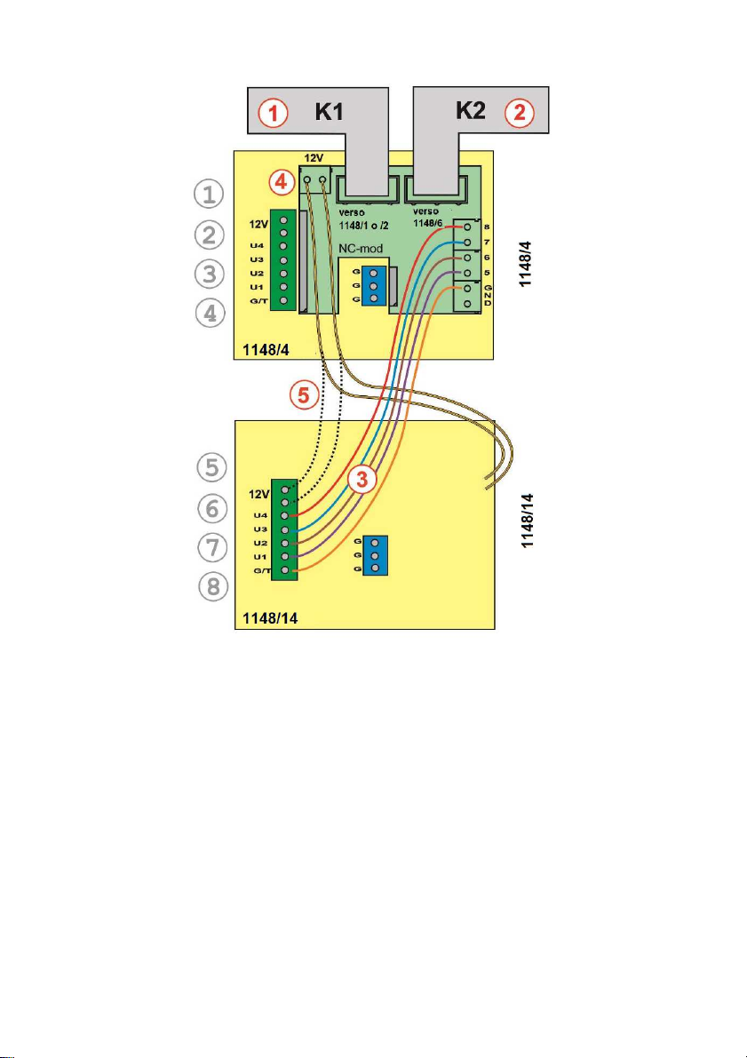
2.3 WIRING AND FLAT CABLE CONNECTION IN DETAIL
Img. 2 Connection of the modules 1148/4 and 1148/14, one level
1) Flat cable towards basic modules
2) Flat cable towards expansion modules
3) Electrical connection for 1148/14 module
4) Connection for nametag lighting
5) Alternative connection for nametag lighting
10 DS1148-014D
Page 11
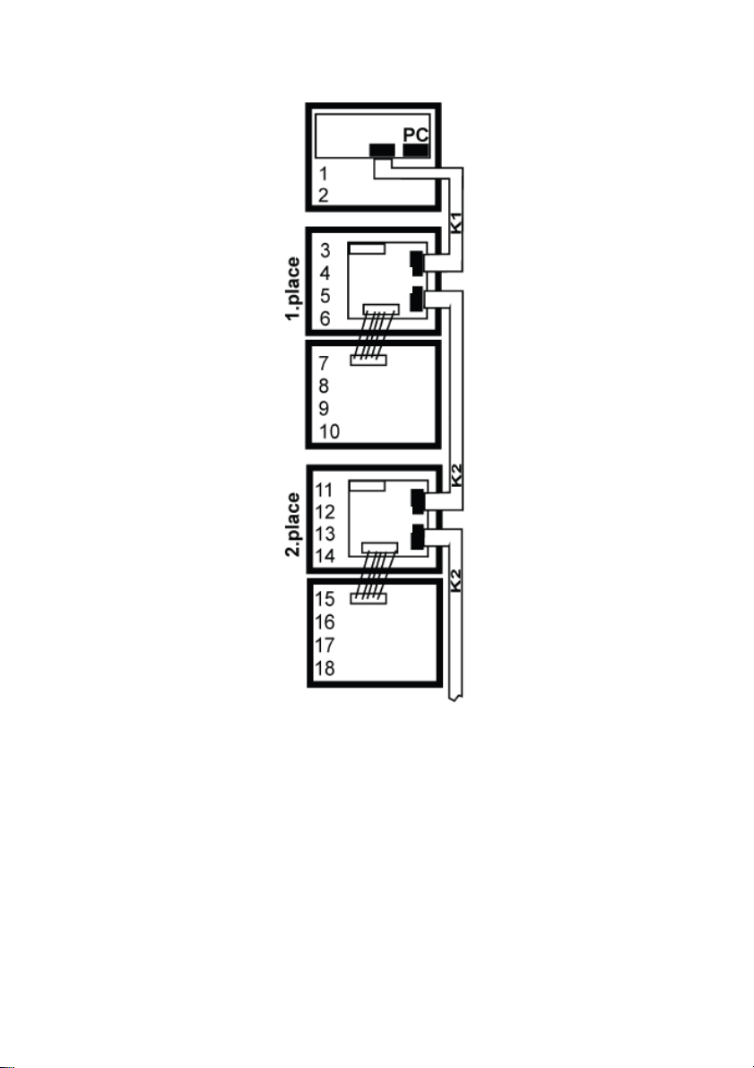
MODULES CONFIGURATION EXAMPLE
1148/1
-2
1148/4
1148/14
1148/4
1148/14
Img. 3 Connection of the modules 1148/4 and 1148/14, two level
DS1148-014D 11
Page 12
2.4 1148/6 KEYBOARD CONNECTION
The connection of the keyboard module is done with one of the 2 flat cables furnished,
starting from the module 1148/1-2 or 1148/4; the only difference is that the keyboard
module can only be connected to the first 8 places following the basic modules. In
addition to that, the keyboard module must be the last one of the modules connected.
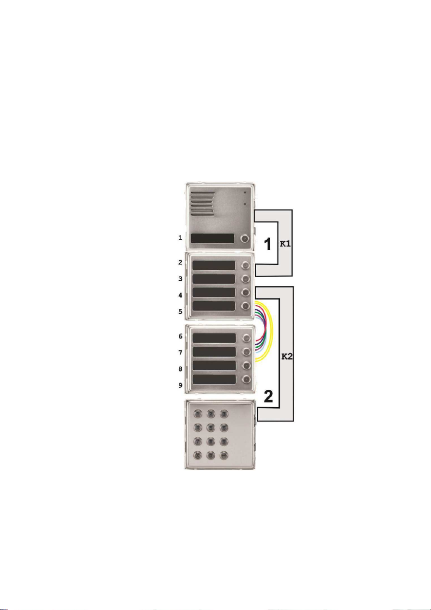
Img. 4 shows the position of keyboard module, 1148/6, where it is connected in second
place after the basic module, (there are 2 cables between the keyboard and basic
module).
Be careful when programming – It is necessary to determine exactly where the
keyboard is connected (see parameter 48 described on the complete manual, section
Programming).
Img. 4 also shows the position of the 4-button module with a keyboard connected. The
number of buttons on the basic module is set with parameter 6# (section Programming).
1148/1
1148/4
1148/14
1148/6
Img. 4 Example of connection: 1148/1, 1148/4, 1148/14 and 1148/6
12 DS1148-014D
Page 13

The keyboard has 2 basic modes for dialling the phone numbers (parameter 49).
• Direct choice of phone numbers – press numbers on the keyboard like you
would on a phone (max. 24 digits)
• Choice from the door system’s memory – press only 2 digits on the
keyboard i.e. a memory address (01- 99). This option saves the connected
buttons, as it is easier to use a smaller number of buttons for direct dialling
from the memory file if you have a larger number of users.
Note: button 1 on the basic module uses the same memory of telephone number as
option 01 on the keyboard – there memory for up to 99 day-time numbers and 99 nighttime numbers, the keyboard uses the same memory as the buttons!
You can set the DTMF dialling option with parameter 40 during a phone call (section
Programming).
Whatever programming is made, the button disconnect or cancel.
2.5 INSTALLATION OF THE DEVICES
Flush mounting
For this type of installation use the mounting boxes 1145/51-52-53-54 and possibly the
rain hood 1158/611-612-613-614. Be careful about the orientation of the openings; for
the assembly if you use the built-in box 1145/51 - must be in vertical axis.
The protective frame, which provides the coverage of the irregularities once walled box,
and the rain hood, needed for the installations in outdoor areas, constitute other
accessories useful for this type of installation.
Wall-mounted installation
For this type of installation use the enclosures with built-in rain hood 1148/311-312-313-
314. If your installation is in an environment with the possibility of condensation (sudden
temperature changes) or rain, it is recommended to put the DIP switch 2 in position ON
- Active heating.
The board heating has two positive functions: in part heats the circuits in winter and in
part prevents the formation of condensation inside it.
2.6 CONNECTION
The basic function (activation and deactivation of a call) only requires the connection of
a telephone line (Img. 1 Line 9). The line is connected with two conductors (a, b) and
generally has a voltage of 24V - 60V, short circuit 20mA - 60mA. During the
conversation, the line voltage is 7V - 10V.
Line Activation – The 1148/1 or /2 Sinthesi S2 module emits a tone (Reset) if it was
previously disconnected from the line for a certain period of time (see tone table of the
complete manual).
The 1148/1 or /2 Sinthesi S2 module is an analog combiphone designed to be
connected to an analog telephone line. The polarity of the telephone line is not relevant.
The module works based on the configuration of the programming parameters.
Parallel connection - it is not recommended, because the parallel connection with
another door phone or telephone line causes technical problems. Also it is not possible
to use different devices for a line switching (adapters of intelligent line, etc.).
DS1148-014D 13
Page 14

The relay (Img.1 7) have multiple uses; some connection examples are shown on
the next page. To make the system work properly you need to connect the power supply
9000/230. The Door Phones system is designed so that all parts are galvanically
isolated. The telephone line is separate feeder and also the relay contacts are
galvanically isolated from other parts of the intercom system. This avoids interference
issues and interactions.
ATTENTION !!! Connect to relay only SELV circuits. Maximum current allowed
by the contacts 1A@48V oppure 1,5A@30V.
14 DS1148-014D
Page 15
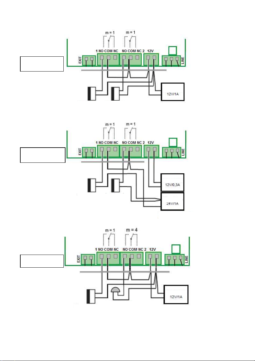
RELAY CONNECTION EXAMPLES
EXAMPLE 1
Power Supply
EXAMPLE 2
EXAMPLE 3
Electric lock 1
Electric lock 1
Electric lock 2
Electric lock 2
For relay lighting and
control
Power Supply
Power Supply
To power the electric lock
Power Supply
Electric lock 1
Additional bell
DS1148-014D 15
Page 16
1. Basic connection: 2 electric locks and the possibility to manage two doors
independently (relay mode 1 and 2 m = 1) or the gradual opening of a door
(relay mode 2 m = 5).
2. Two power supplies: ability to use two power supplies, one for the 1148/1
module or / 2 and one for an electric door lock. The electric lock 2 is connected
in reverse (fire safety door).
3. Combination of an electric lock and an additional bell. The relays for
additional bell can be in m = 4 mode (each key activates it for a period of time
configured) or m = 6 mode (activated by a default key for a duration of time
configured).
4. Combination with electric door and electric gate
5. Gate opening with impulse relay and light switching environment (SELV
or relay) with relay ON / OFF; in this case it is essential to use an external
power supply since the relay 2 remains constantly switched (DIP3-DIP4 ON)
N.B. The examples are purely for illustrative purposes.
Note: Urmet 1148 Sinthesi S2 system is designed so that you can connect 10-
18Vac or 11-24Vdc to 12V terminals (polarity is not relevant).
The heating device of the motherboard is equipped with a controller so that the
resistances do not burn as a result of an increase in tension.
2.7 ACCESSORIES
USB programming interface
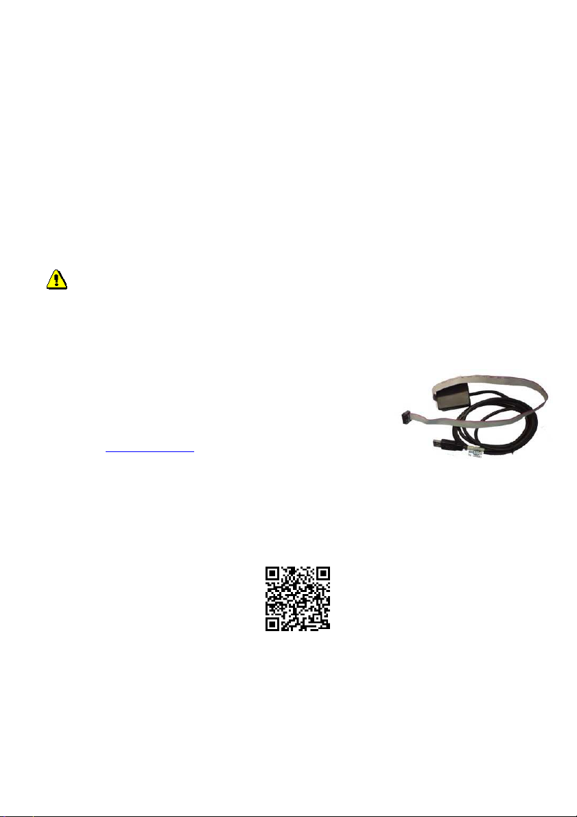
The USB interface 1148/9 is used to program by pc the
combiphone door unit Sinthesi S2. From the Download area
of website www.urmet.com are available:
Software and USB interface driver for PC installation.
Download Software Technical Software Communication
Combiphone Door Unit (Note: for registered users only)
The complete programming software manual.
Download Documentation User Manuals
16 DS1148-014D
Page 17
3 Door Entry System Operation
The door entry system’s functions are set by establishing parameters (see the
section of parameter programming).
3.1 Signalling overview
The combiphone Sinthesi S2 acoustic signals occur during its operation. Samples
of sounds can be listened to in the setting programme Urmet-1148-tel.
State Tones Tone frequency
Pick up line type 1 –▄■▄■▀– 980-1333-1650
Disconnection of line type 1 –▀■▄■▄– 1650-1333-980
Pick up line type 2 –▄■▀–
Disconnection of line type 2 –▀■▄–
800-1067-12001333
1333-1200-1067800
Confirmation of command from the phone ––█–– 800
Ticking during a call ─┴─┴─
Notice about the end of a call –■–■–■– 1333
Relay switch signal ─▒▒▒▒▒▒─ Modulated
Entry into programming from the phone –▄■▀– 980-1067-1180
Programming from the phone ––▓–▓––––– Modulated
Parameter confirmation ––█–– 800
Entry into programming from the PC –▄■▀– 980-1067-1180
Line connection (Reset) –■–▄–■– 1850-1067-1850
Error (generally something is not right)
–■–■–■–■–■–
■–
800
Empty memory (no number is programmed) –▄■▄■▄■▄■– 1300-2100
It is useful to know what tones the combiphone Sinthesi S2 plays during
installation as it will assist in the analysis of its state and operation. The sounds can be
turned off in several levels (parameters 61,62,63 and 65).
3.2 Caller at the door
The door entry system’s buttons are labelled in the same way as normal doorbell
buttons. Visitor finds the appropriate name and presses the button. The combiphone
1148 will pick up a line, "plays" the pick up line tone (if not disabled, see par. 62) and
dials the phone number saved under that button (parameter 1 or 2 depending on system
mode). From the combiphone speaker a ringing tone will be heard and the user phone
will ring. As soon as the user called picks up he can talk to his visitor. If an electric lock
DS1148-014D 17
Page 18

is also connected to the combiphone, the user can press a DTMF code on his phone
and let visitor in. If he hangs up the phone the combiphone will disconnect. If the call
lasts longer than the pre-set limit (parameter 52), 10sec before disconnection the
combiphone will send a line disconnection tone, but the user can dial * or # (parameter
42), to prolong the call for the length of time set in parameter 52.
The dialled number depends on the mode set in the system (parameter 47):
- Day/Night Mode = if the system is in ‘Day’ mode, it dials the number set in
parameter 1, if the system is in ‘Night’ mode, it dials a number set in parameter 2.
The switching over the modes manually is set in parameters 45, 46.
- 2 groups of numbers Mode = the first press of the button always dials a number
set in parameter 1. Following the repeated pressing of the same button, when it
detects a busy tone (10sec after choice), or after a pre-set number of rings
(parameter 56) the system dials a number from the second group (parameter 2).
After another press of the same button the system will again dial the number from
the first group (or after detecting a busy tone on the dialling of a number from the
group 2 the repetition ends).
If a visitor presses the button after the system has picked up, the system will
disconnect for a length of time as set in parameter 54 before it picks up the line and
dials a new number. The number choice takes place either by tone (DTMF) or impulse
according to the setting in parameter 41. There is one more option, disconnection of
line after repeat pressing of the same button (parameter 4*).
It is possible to control a relay switch (code lock) with the first 10 buttons. If
visitor at the door presses buttons in the correct combination according to a preprogrammed code (parameter 32-34) and the length of time between presses isn’t
greater than the pre-set time (parameter 53) the system picks up, switches the
appropriate relay (if it is set in mode m=1 or m=5) for the length of time given in
parameter 37 or 39,30 and then disconnects.
Relays can switch on one or two impulses depending on control code with the
length of time between impulses set in parameter 30.
18 DS1148-014D
Page 19
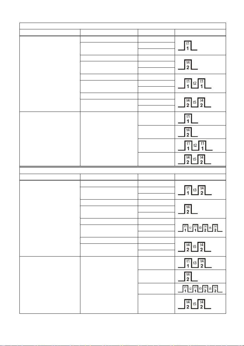
3.2.1 Tab. 1 – Table of relay controls
Mode
m = 1
Action
Note
Parameter
Relay
Evaluation of correct
Internal code from
Mode
m = 5
Action
Note
Parameter
Relay
Evaluation of correct
Internal code from
(parameter 3111 and 3121)
3211-3215
internal code from
the buttons
the phone
internal code from
the buttons
According to setting
Day/Night
3221-3225
According to setting
Day/Night
321*
According to setting
Day/Night
322*
According to setting
Day/Night
Option to choose 1 or
2 digits of code
2 digit code is basic
and it is possible to
shorten it by using *
in the first place of
code during
programming
(parameter 3125)
3211-3215
According to setting
Day/Night
3221-3225
According to setting
Day/Night
321*
According to setting
Day/Night
322*
According to setting
Day/Night
3311-3315
3411-3415
3321-3325
3421-3425
331*
341*
332*
342*
351
352
361
362
3311-3315
3411-3415
3321-3325
3421-3425
331*
341*
332*
342*
the phone
DS1148-014D 19
Option to choose 1 or
2 digits of code
2 digit code is basic
and it is possible to
shorten it by using *
in the first place of
code during
programming
351
352
361
362
Page 20
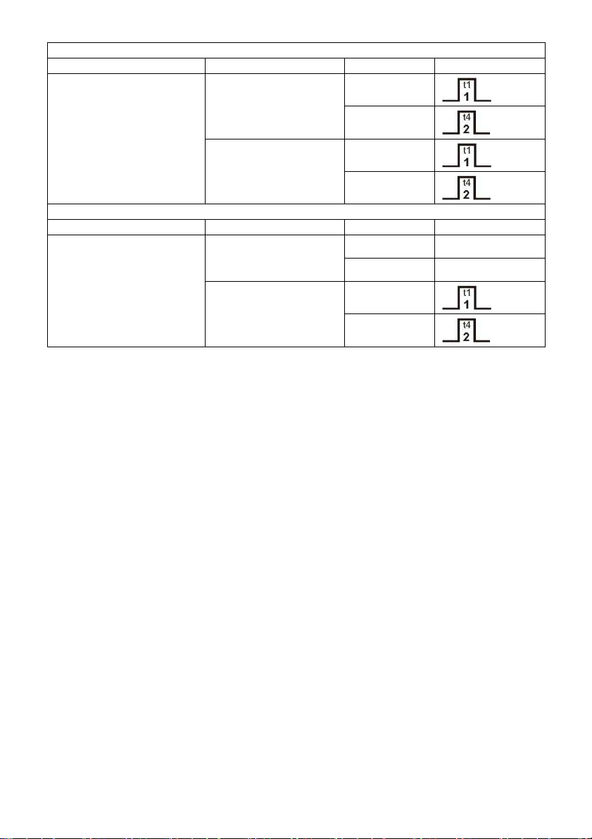
Mode
m = 4
Action
Note
Parameter
Relay
Press buttons
Mode
m = 6
Action
Note
Paramet
er Relay
Press of the button
Any number other
than in 311* or 312*
Button set in 311* or
312*
Any number other
than in 311* or 312*
Button set in 311* or
312*
3114
3124
3114
3124
3116 -
3126 -
3116
3126
Note t1 – time of connection of relay 1 (parameter 371)
t2 – time between impulses of relay 1 (parameter 301)
t3 – time between connections of relay 1 and 2 (parameter 39)
t4 - time of connection of relay 2 (parameter 372)
t5 - time between impulses of relay 2 (parameter 302)
3.2.2 Outbound call
An outbound call is a call from the combiphone system (i.e. started by a visitor).
Once the system has been dialled, a phone inside of the building rings and on pick up it
is possible to talk to the visitor at the door. By choosing a code it is possible to switch on
a relay (parameter 35) if it is set in mode m=1 or m=5, switch over the Day/Night mode
(parameter 45, 46) and disconnect the connection (parameter 43). 10sec before the end
of the call (parameter 52) the system sends a notice about the end of the call but
choosing a code (parameter 42) it is possible to prolong the call. By replacing the
handset the call is terminated (the switchboard phone will send a system busy tone and
the system will disconnect). There is one more option, disconnection of line after repeat
pressing of the same button (parameter 4*).
3.2.3 Incoming call
An incoming call is a call to the 1148 module made by a telephone which dialled
the number of the line where the 1148 is connected. After choosing the branch the
system is connected and the line rings, following a set number of rings (parameter 51)
the system will then pick up and it is possible to speak. The options are the same as an
‘outgoing call’.
• One exception is in the first 10sec. when it is also possible to input ‘# and a
service password’ (parameter 44) directing the system to go to the programming
mode.
• Another exception is during incoming call and DIP1 is switched to on when the
system also goes to the programming mode (without a service password).
20 DS1148-014D
Page 21
• The final exception is relay controls (parameter 381 and 382), when an incoming
Hang u
Answer
call can disable the relay controls.
3.2.4 Door Entry System with keyboard – 1148/6 module
If a keyboard module is connected to the system, then it is necessary to set the
following parameters:
• parameter 48 – rank of the keyboard. If it is ‘set 0’, the keyboard is not there, if
it is ‘set 1 – 8’, then this number represents a position where the keyboard is
connected on the BUS (represents the number of flat cables between the
keyboard and the basic module).
• parameter 49 – keyboard mode.
o If it is 0, then the phone number from the keyboard is dialled in the
same way as from a phone. The visitor enters a number combination
and after a length of time, set by the max time between key presses
(parameter 53), the combiphone picks up and dials the given number.
o If 1 then the keyboard choses a 2 digit combination 01-99 as per the
memory address, where a telephone number is saved. The memory is
the same (shared) as the button memory. The number choice
depends on the Day/Night setting.
• parameter 40 – choses the DTMF from the keyboard during a call.
•
Parameter value 40
Meaning of symbol
0 No DTMF from the keyboard
1 DTMF *
2 DTMF #
3 DTMF A
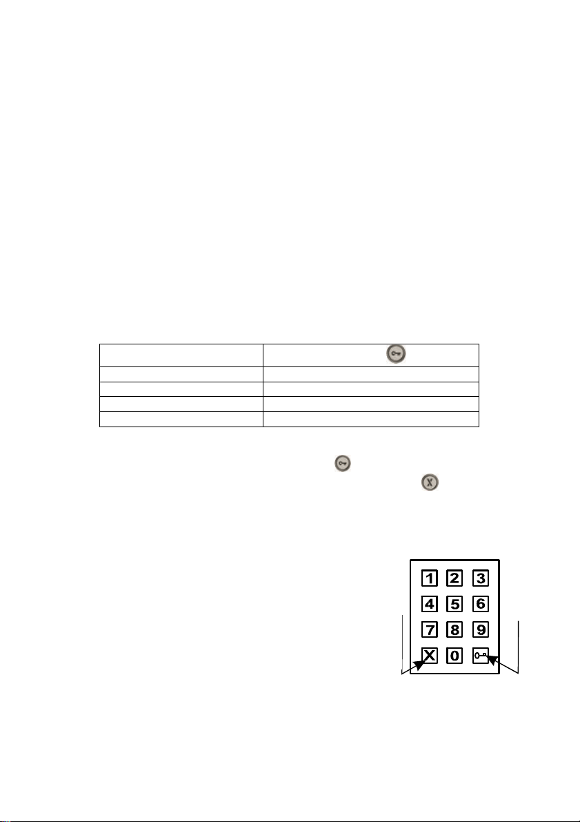
The keyboard has 2 functioning keys – key symbol = before pressing a combination
of digits corresponding to control relays. Second key – symbol X = after pressing
the system always disconnects.
Choosing number on the keyboard can be done in two ways (parameter 49):
- visitor chooses keys like on a phone – the length of time between the presses
must be less than the time given in parameter 53, after this the system picks
up and dials the given number.
- Visitor chooses a 2 digit number (from 01 to 99),
which represents a memory number where a
number is saved (max. 24 digits long) as per the
buttons. The number choice depends on the
setting mode (i.e. Day/Night) or by 2 groups of
p
numbers mode (as described in paragraph 5.1).
DS1148-014D 21
Page 22

3.3 Acoustic path setting
The principle of setting acoustic paths:
Here we have three parameters 71.72 and 73 Using the interaction of these parameters
can be set to sound in different conditions.
1. Quiet environment parameters 71,72,73 are set to 7
2. Environment where is a strong ambient noise at the communicator and quiet
environment at the phone. Here is both necessary to reduce the microphone gain
(parameter 72 = 1-3) and also change the ratio of the parameters 71/73, encreasing
the parameter 73 (parameter 73 = 11-15) and reducing the parameter 71 (71 = 2-
4).
3. Environment where is a strong ambient noise at the phone and quiet environment
at the communicator. Here we leave the parameter value of 72 = 7 and 73 and 71
parameters set as follows - parameter71 = 11 to 14 and 73 = 2 to 4
The principle of parameters setting is - signal from the microphone is amplified by the
sum of parameters 72+71 = volume of microphone and signal to the speaker is
amplified by the sum of parameters 71+73 = volume of speaker. To switch the
direction of the ratio is evaluated parameters (threshold) 73/72.
- If parameter 72 is greater than the parameter 73, thus favoring the direction
from the microphone. We choose when the direction to the phone is
interrupted.
- If parameter 73 greater than parameter 72, thus favored direction to the
speaker. We choose this if the interrupted sound in the speaker of
communicator.
22 DS1148-014D
Page 23

4 Parameter programming
4.1 Programming with the help of a phone
4.1.1 Entry into the programming
There are two ways to enter the combiphone programming system:
1. With the help of a password –incoming calls only! – pick up a phone and dial
the number that the combiphone is connected to (either the number of the
branch, if you are connected to a switchboard line, or the number of the line to
the building, where the combiphone is and ask to be connected to the branch
to which the combiphone is connected). The module will pick up (you will hear
the pick-up tone – see paragraph 3.1), within 10 secs. press ‘#xxxx’, where
xxxx is the service password to enter the programme system (in the basic
setting xxxx=0000), if correct there will be a programming entry tone followed
immediately by a programming tone.
2. With the help of DIP 1 – incoming call only! – connect to the combiphone as
in part 1 above, but where the DIP switch is in position 1 “on”, the combiphone
will go straight to the programming mode – you will hear the pick-up tone for
entry to programming followed immediately by the programming.
Do not forget to put DIP switch to position “off” at the end.
4.1.2 Parameter programming
The default state for programming is announced with a programming tone, the
combiphone always returns to this state after a specified time (5sec), whether you
started programming or not.
There are two types of parameters used during programming. These are
parameters with a fixed length, which is the majority of them, when programming is
confirmed after it fulfils the mandatory length and is immediately ‘written in’ with a
confirming tone and parameters with variable length (parameters 1,2,32,33,34) when
the confirmation is made only after time of inaction (5 sec). The only case when there
is an immediate ‘writing in’ of parameters is when the maximum number of ‘written in’
signs (numbers) are filled up, for parameters 1 and 2 it is 24, for parameters 32,33,34 it
is 6.
If you input a number (sign) that is unacceptable during the programming the
combiphone immediately sends an error tone, the parameter is not ‘written in ‘and the
combiphone reverts to a default state where it is possible to either repeat the parameter
programming or start programming a different parameter.
The combiphone will automatically disconnect form the programming mode after
a period of inaction, 30 sec. With each DTMF tone dialled the time will always resets to
30 sec. It is also possible to end the programming mode by choosing parameter 9.
Note. If you want to keep a connection opened during the programming (prolong the 30
sec time) mode, i.e. before a customer decides what else he wants to be set, then you
can press * or #. The combiphone immediately answers with an error tone but will
prolong the time before disconnecting.
DS1148-014D 23
Page 24
5 Description of programmable parameters
Parameters always start with a fixed/mandatory part (address) followed by a
variable part, which is your choice. The range and explanation is always under the table,
sometimes with examples. Everything is dialled exactly as it is shown in the table,
nothing needs to be confirmed in any way, after writing into a memory a confirmation
tone can be heard and if an incorrect value is input then an error tone will be heard.
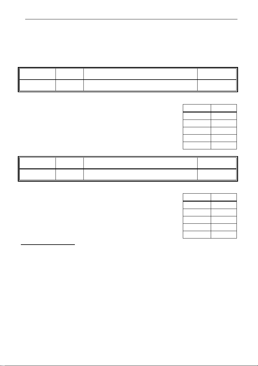
5.1 Direct dialling - memory
Parameter Value Meaning Basic
1 tt nn… number nn under button tt
tt – button number (memory), always input 2 digits [01-99]
nn – telephone number as long as 24 digits that are to be
saved. For saving of other sign choices always use the
assignation as per the table.
Numbers saved in parameter 1 are numbers of the first group,
or numbers of the Day mode.
Basic settings never change or delete these saved numbers.
Parameter Value Meaning Basic
2 tt nn… number nn under button tt
tt – button number (memory), always input 2 digits [01-99]
nn – telephone number as long as 24 digits that are to be
saved. For saving of other sign choices always use the
assignation as per the table.
Numbers saved in parameter 2 are numbers of the second
group, or numbers of the Night mode.
Basic setting never change or delete these saved numbers.
Examples of setting:
1. first button is supposed to dial 358 during the day and 0603441296 during the night,
then the programming is - 101358 and wait for ♫, then 2010 *0 603441296 and wit
for ♫
2. second button is supposed to dial 123#1*2Flash3 during day and night, then the
programming is 102123#1 ** 2 *# 3 and wait for ♫, then 202123#1 ** 2 *# 3 and wait
for ♫
Note. If you are not using Day/night mode or 2 groups of numbers mode, then it is
recommended to set Day/Night mode (parameter 47) and then set the same code for
switching over Day/Night (parameters 45 and 46). This way ensures that the
combiphone will always be in Day mode and you can only programme telephone
numbers for the day mode (parameter 1).
-
meaning choice
0 - 9 0 - 9
# #
* **
Flash * #
Pause * 0
-
meaning choice
0 - 9 0 - 9
# #
* **
Flash * #
Pause * 0
24 DS1148-014D
Page 25
5.2 Relays
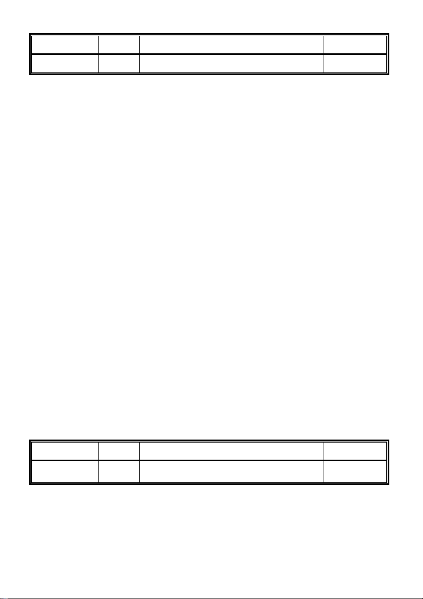
Parameter Value Meaning Basic
31 r m relay r operates in mode m (1-8)
11 21
r – relay number [1-2]
m – relay mode [1-8 for r=1 is not mode m=5]
The modes m=1, 4, 5, 6 are explained in detail in Relay Modes Table.
m=1 mode relay – switched on with command (internal code) or with a password
(external) 1 impulse for length of time t1/t4 (use for electric locks) or 2 impulses
when it switches on for time t1/t4, off for t2/t5 and again switches on for t1/t4
(opening of sliding gates).
m=2 is switched on for time when the line is picked up (camera) – switches on when
system picks up and off when it disconnects.
m=3 is switched on for time when the line is picked up and extra time t1/t4 after
disconnection (lights) - switches on for time when the line is picked up and extra
time t1/t4 after disconnection (for this time the line is busy, with version is after
switching DIP 3, 4 and setting of parameter 64 line after t1/t4 disconnected)
m=4 button mode– switched on when any button is pressed and off after t1/t4 (use is
for example connection of external bell or siren)
m=5 gradual opening mode – it is possible to set only relay 2, because relay 1 will
then automatically be set to m=1. With command (internal code) or password
(external code) relay 1 is activated for length of time1, then time t3 is running
before relay 2 is switched, then relay 2 is activated for time t4 and after the
system disconnects. If given command or password answers to 2 impulses then
in the sequence there will be always 2 impulses separated by time t2/t5.
Explanation is in Tab.1.
Note. Command or password for relay 1 starts the whole sequence, if you use
command or password for relay 2 then only relay 2 is controlled in the same way
as in m=1 mode.
m=6 switches on depending on pressed button (it is set in parameter 31r*). In this way
it is possible to choose only one button for each relay, which when pressed
switches on relay for time t1/t4. This mode is used instead of connecting
separate doorbell to the system.
m=7 permanent switch on / off – only for switching (DIP 3, 4). With command for 1
impulse it is switched on, for impulse 2 is off. The system remembers its state
even after the line is disconnected. This mode is used for watering, green house
opening, switching on heating etc.
m=8 function not available at the moment
Parameter Value Meaning Basic
31 r* tt
button tt switches on relay r in m=6 mode
(01-99)
01
r – relay number [1-2]
tt – module button number, always in two digits [01-99]
This parameter is only for relay mode m=6. Value tt determines which button activates
the r relay for time t1/t4.
DS1148-014D 25
Page 26
Parameter Value Meaning Basic
Day + Night
hh
...
Day
mode
hh...
Night
mode
hh...
32 rp hh...
In
relay r, in order p=1-5 for 1 impulse and
mode password
for
-
p=* for 2 impulses (00-999999)
33 rp hh...
In
order p=1-5 for 1 impulse and p=* for 2
password
for relay r, in
-
impulses (00-999999)
34 rp hh...
In
in order p=1-5 for 1 impulse and p=* for 2
password
for relay r,
-
impulses (00-999999)
r – relay number [1-2]
p – order [1 - 5] for 1 impulse. 5 passwords (external codes) from combiphone
buttons (external code of code lock)
p – order = * to set password (external code) for 2 impulses
hh... – password (external code) for relay switching on from button or keyboard [2 to
6 places]. Buttons 1 - 10 are programmed as numbers 1-0.
Switching on a relay is affected by the relay mode and the choice Day/Night, if the 2
groups of numbers mode is set, the system is constantly in DAY mode. See chapter
5.1
There are several rules that needs to be followed when setting a password:
Choose the first button of password from buttons that are the least used for
direct dialling (-prolonging time) (n/a for keyboard).
Be mindful about conformity of numbers (i.e. when 1 password contains
another for example for relay 1 it is 1234 and for relay 2 12345) as the first
password will start the action once button 4 is pressed and you will never be
able to input button 5 to start action for password 2, and if you choose 234 for
a second relay, then after pressing 4 both relays will start.
Note. When setting parameter 32,33,34 signs # and * are not used because they are
not on the button panel, number 0 represents button no. 10.
Parameter Value Meaning Basic
35 r aa
command aa from phone for switching
relay r 1 impulse (00-99,*0-*9)
155 266
r – relay number [1-2]
aa – command (internal code) for switching on the relay from the phone [2 spaces]
/1
To set the same commands for both relays (internal code) so that both relays activate at
the same time. It is also recommended that the same command is set for ‘relay on’ and
‘command to disconnection of system (parameter 43) aa=bb.
/1 – command is always 2 digits, but if you wish to control relay with a single digit from
the phone, there is an option to input "*a", where a is a single number and the star
represents an empty space and must be in the first place.
Example:
1 relay switch on internal code 48 – is programmed 35148 ♫
2 relay switch on internal code 8 - is programmed 352*8 ♫
26 DS1148-014D
Page 27
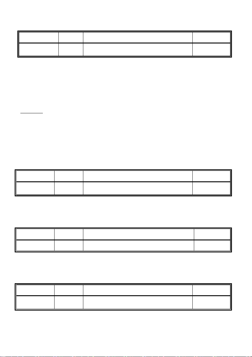
By choosing no 8 on the phone we switch on just the second relay, with option 48 we
t1/t4
switch on both relays
Parameter Value Meaning Basic
36 r cc
command aa from phone for switching
relay r 2 impulses (00-99,*0-*9)
150 260
r – relay number [1-2]
cc – command (internal code) for switching on the relay from the phone [2 spaces]/1
To set the same command for both relays (internal code) so that both relays activate at
the same time
/1 – command is always 2 digits, but if you wish to control relay with a single digit from
the phone, there is an option to input "*a", where a is a single number and the star
represents an empty space and must be in the first place.
Switching a relay on with 2-impulses is used for sliding gates replacing a gate entry.
Example:
Command for switching on 2 relays 1 impulse is for example *8, the command for
disconnection is *8 and the command for switching on 2 relays 2 impulses is *9.
Programming: 352*8 ♫ , 432*8 ♫ , 362*9 ♫.
If you are in conversation with the combiphone, the command to open a gate would be
button 9, the first impulse starts and the gate opens, the second impulse stops it, the
time the gate is opened "opened space" is set by time between the impulses (parameter
30) after people enter press 8, then combiphone makes 1 impulse and disconnects,
gate closes.
Parameter Value Meaning Basic
37 r ss
time ss [sec] of relay r on for time
(01-99)
105 205
r – relay number [1-2]
ss – time t1 / t4 for which relay 1 / 2 is switched on [2 spaces 00-99], where time 00
means 0,5sec
Parameter Value Meaning Basic
38 r p relay r control during incoming call (0/1)
11 21
r – relay number [1-2]
p – parameter whether it is allowed p=1 or disallowed p=0 to control relay during
incoming call.
Parameter Value Meaning Basic
39 xx
time xx [sec] between switching on relays
1 and 2 in m=5 mode - time t3 (01-99)
10
xx – time t3 between switching on relays 1 and 2 when m=5 mode is set (gradual
opening) [2 spaces 00-99] ], where time 00 means 0,5sec
DS1148-014D 27
Page 28
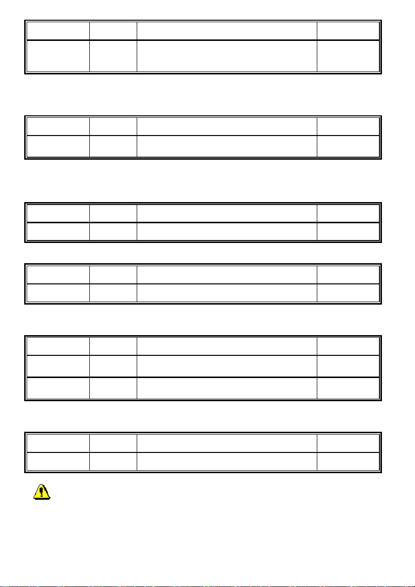
Parameter Value Meaning Basic
time zz [sec] between impulses for
30 r zz
switching on relay r 2 impulses- time t2/t5
105 205
(01-99)
r – relay number [1-2]
zz – time t2 / t5 between first and second impulse for switching on relay 1 / 2 [2
spaces 00-99], where time 00 means 0,5sec
Parameter Value Meaning Basic
3* r e
Relay activation through Exit button (see
fig.1)
10 20
r – relay number [1-2]
e – exit button mode: e=0 - off, e=1 – on for 1 impulse, e=2 – on for 2 impulses
5.3 Basic parameters
Parameter Value Meaning Basic
41 v Type of choice v – time/impulse (0/1)
0
v – type of choice v=0 is DTMF tone choice, v=1 is impulse choice
Parameter Value Meaning Basic
42 z
Sign for call prolonging (* / #) *
z – sign for prolonging a call * or # (10secs. before the end of the call the
combiphone sends signal, after pressing it prolongs the call)
Parameter Value Meaning Basic
431 bb
432 bb
Command for disconnecting the
combiphone from the phone (00-99,*0-*9)
Command for disconnecting the
combiphone from the phone (00-99,*0-*9)
55
66
NOTE. It is advantageous to set the same command for relay switching on (parameter
35,36) and command for the combiphone disconnection.
Parameter Value Meaning Basic
44 xxxx
Service password (0000-9999) 0000
xxxx – service password to programme from a phone (DTMF)
If you forget the password, the following procedure is recommended:
1. Open the combiphone front cover
2. Switch ‘DIP 1’ to ‘ON’
3. Call the combiphone
28 DS1148-014D
Page 29
4. Once the combiphone picks up the system is in programming mode. In this
DAY
NIGHT
mode it is possible to change the password 44xxxx
5. Switch ‘DIP 1’ to ‘OFF’
6. Close the front cover.
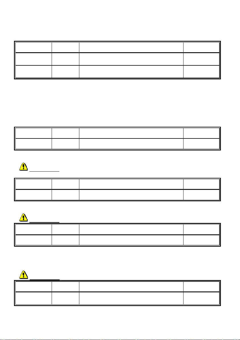
Parameter Value Meaning Basic
45 dd
46 nn
Command for switch over to
(00-9,*0-*9)
Command for switch over to
(0099,*0-*9)
11
10
Dd command to switch over to the DAY mode [2 spaces] /1
Nn command to switch over to the NIGHT mode [2 spaces] /1
/1 command is always 2 digits, but if you wish to switch over from Day to Night with
a single digit from the phone, there is an option to input "*a", where a is a single
number and the star represents an empty space and must be in the first place
(e.g. parameters 35,36)
Note. The Day/Night switch over mode stays set following line disconnection.
Parameter Value Meaning Basic
47 e
System choice mode (0/1) 1
e – Choice of mode numbers e=0 selects numbers from first and second group, e=1
selects numbers in accordance with the Day/Night mode.
WARNING !! setting this parameter materially affects the number dialling!
Parameter Value Meaning Basic
48 c
Keyboard connection (0-8) 0
c – c=0 connecting the 1148/4 module to the basic module only
c=1 - 8 keyboard connected to the first to eight place
WARNING !! setting this parameter materially affects whole systems function!
Parameter Value Meaning Basic
49 o
Keyboard Mode (0/1) 0
o – o=0 choses a number like a phone (input the whole number)
o=1 input a 2 digit number (memory) on the keyboard, where the number is saved
into the memory (the memory number is the same as button number and respects
Day/Night switch over – numbers 01 - 99)
WARNING !! setting this parameter materially affects keyboard function!
Parameter Value Meaning Basic
40 d
Choses DTMF from the keyboard during a
call (0-3)
0
d – d=0 during a call it is not possible to dial DTMF from the keyboard
DS1148-014D 29
Page 30
d=1 DTMF can be dialled, the Key button dials *
d=2 DTMF can be dialled, the Key button dials #
d=3 DTMF can be dialled, the Key button dials A
Parameter Value Meaning Basic
4* k
k – Repeatedly pressing the same button to disconnect the line (if still active):
k=0 function disabled k=1.function enable
WARNING !! setting of this parameter materially affects number dialling!
5.4 Time parameters
Parameter Value Meaning Basic
51 q
q – The number of rings before an incoming call is picked up. The combiphone picks
up between rings 2 secs. after detecting the q-th ring. It is possible to set the
number of rings between 1 and 9.
Parameter Value Meaning Basic
Line disconnection function by repeatedly
pressing a button (0/1)
Number of rings before the combiphone
picks up (1-9)
1
2
52 d
d – The maximum length of time for which the combiphone is busy. It is possible to
prolong this time during the call by choosing a key (* or #) from the phone
(parameter 42). The setting of this time is in accordance with the adjacent table.
Maximum length of a call (0-9,*,#) 2
Time [min] Option
0,5 0
1 - 9 1 - 9
15 *
30 #
Parameter Value Meaning Basic
53 w
w – maximum time [in seconds] between button presses [range 1 - 9]
Normal buttons
- Relay switch on – if the time between presses is longer than time w, then the
code will not work correctly.
- Choice of number – if the pressed button is the first number of a password to
switch on a relay then the choice is delayed by time w.
Keyboard
30 DS1148-014D
Time between button presses (1-9) 2
Page 31
- Switch on Relay – if the time between presses is longer than the time w then
the code will not work correctly.
- Choosing of number
- Choose from the phone, if the time after the last pressed button is
longer than time w, then the choice commences, if the number is
incomplete, it is necessary to disconnect (press the X key ) and
repeat the choice
- Choose from the memory, if the time after the last pressed button is
longer than the time w, then the choice needs to be repeated.
Parameter Value Meaning Basic
54 z
Time of disconnection for repeat dialling
(1-5)
2
z – Time [secs.] the combiphone disconnects before it picks up again for repeat
dialling (press of a button during a call, detection of busy tone) [range 1-5].
Parameter Value Meaning Basic
55 z
Time before commencing a choice (1-5) 1
z – Time [sec] after the combiphone picks up, before it begins a choice [range 1-5].
This time is different for each switchboard phone system, but generally most
operate within 2 seconds after a line is picked up.
Parameter Value Meaning Basic
56 hh
Number of rings before disconnecting the
current call (04-99)
12
hh This function is available also if it is set the mode of dialling 2 groups of numbers.
Parameter Value Meaning Basic
500 x
501 y
502 z
Medium frequency of tone detector (1-0)
Number of busy tones (2-0) 4
Time length of permanent tone (1-5) 3 (3s)
3 (375475Hz)
x Medium frequency of tone detector is set if there is a non-standard signal from
the telephone switchboard.
y Minimum number of busy tones necessary for detection [2-0], where 0 means 10
busy tones.
z Minimum length of time of a permanent tone (for detection of notification tone at
branch switchboard) [1-5 sec].
DS1148-014D 31
Page 32
Parameter Value Meaning Basic
503 tt
504 mm
Tone length of time for DTMF (tone) choice
(04-16)
10 (100ms)
Time of gap between DTMF tones (04-16) 10 (100ms)
505 f
506 p
Length of flash time (1-6) 1 (100ms)
Length of time of pause/digit gap (1-0) 4 (800ms)
tt Length of DTFM tone choices is specified by the formula:
(entered number) x 10 = time length of tone [ms]
[range 04-16 which is 40-160ms]
m Length of gap between DTMF tone choices is specified by
the formula: (entered number) x 10 = time length of gap
[ms] [range 04-16 which is 40-160ms]
f Length of flash is specified by the formula:
(entered number) x 100 = time length Flash [ms]
[range 1-6 which is 100-600ms]
p Length of pause is specified by the formula:
(entered number) x 100 + 400 = time length of pause
[ms] [range 1-0 which is 500-1400ms]
Time p is the simultaneously length of gap between button
frequency
[Hz]
275-375 1
325-425 2
375-475 3
425-525 4
475-575 5
525-625 6
575-675 7
625-725 8
675-775 9
725-825 0
x -
choice
taps for an impulse choice.
Parameter Value Meaning Basic
507 uu
Transmit level of DTMF choice v [-dBm]
(04-16)
10
uu Transmission level of (DTMF) choice to the line, the range is -4 to -16dBm, input
the required level where uu=04 is -4dBm, uu=10 is -10dBm
Parameter Value Meaning Basic
508 p
509 S
Pre-emphase DTMF (0/1) 0
Listening in DTMF – level (1-4) 2
p Pre-emphase is the ratio of the upper and lower groups of DTMF frequencies. It
is possible to choose ratio 2.2 dB - p=0 (Europe) or ratio 3.2dB - p=1 (Australia)
s Choice of DTMF volume levels (4 levels):
Volume in DTMF [dB] s - choice
-15 1
-9 2
-3 3
+3 4
32 DS1148-014D
Page 33
5.5 System parameters
Parameter Value Meaning Basic
61 z
The combiphone comes with standard acoustic signals. However, using parameter “z”
it is possible to switch off the acoustic signals. The values are:
z=0 Acoustic signals off / z=1 Acoustic signals on.
Parameter Value Meaning Basic
62 v
The acoustic signals for the connection and disconnection of a line are standard, but
this may cause false choices with some phone systems. So using parameter “v” it is
possible to switch off these signals. The values required are:
z=0 Introduction/conclusion signalisation is off
z=1 Pick up and disconnection signalisation on (intro/concl.- type1)
z=2 Pick up and disconnection signalisation on (intro/concl.- type2).
Parameter Value Meaning Basic
Acoustic signals (confirmation, error, empty
memory, end of call) (0/1)
Acoustic signals introduction/conclusion
(0/1/2)
1
2
63 u
Ticking during a call is switched off as standard. However, by switching it on you can
differentiate on the switchboard a call from the combiphone by a faint ticking. The
values are:
u=0 Ticking into a call is off / u=1 Ticking into a call is on
Parameter Value Meaning Basic
64 w
The external power supply is turned off as standard.
You only need to turn this function on if the combiphone relays operate in m=7 or m=8
mode. The parameter activation w=1 is determined setting DIP switch 3 and 4 to "ON".
Off - w=0.
Parameter Value Meaning Basic
65 z
The acoustic signal for switching on a relay is disabled by default, z=0. However, it is
possible to use this function when using the optional power supply, so when the door
lock is open there is no buzzing so the person at the door won’t know the door is open.
When set to z=1 the time the relay is switched (door open) then there is a specific sound.
Note1 This function is available only for m=1 and m=5 mode.
DS1148-014D 33
Acoustic ticking signal during a call (0/1) 0
Internal power supply from connected
supply 12V (DIP 3,4 set to ON) (0/1)
Acoustic signals for switching on a relay (0/1) 0
0
Page 34
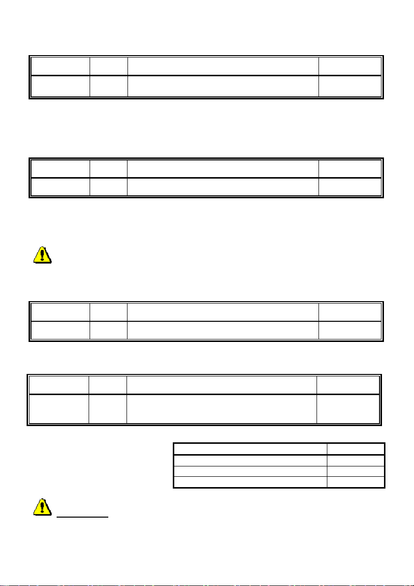
Note2 During the relay switch-on (2 impulses) there is acoustic signal for the whole time
s -
choice
of the sequence (even during gap between impulses).
Parameter Value Meaning Basic
66 i
Suppression of the reception DTMF from the microphone is off as a default i=0. It is
possible to open the door with a personal dialler without disturbing a person inside the
building. For higher security it is possible to switch on the suppression function i=1 and
stop a person with an unauthorised copy of the DTMF code from entering.
Suppression of the reception DTMF from the
microphone (0/1)
0
Parameter Value Meaning Basic
67 b
This function is turned off as standard b=0, so after pressing a button with an empty
memory there is an error acoustic signalization. By switching on this function b=1 the
acoustic signal for an empty memory is cancelled.
Warning: During the first 10 seconds of a call the tone detector is inactive (there is
a pause before the switchboard responds or number dialling by the switchboard).
Default is off m = 0 By enabling the m = 1 mutes the acoustic path at close relay (1 or 2) in
Signalization of not set button (0/1)
0
Parameter Value Meaning Basic
68 b
"electric lock" (modes 1 and 5). This feature is there because if you often use code lock
function or exit button, so the switch-on time to hear the tone exchange. For some
customers, this can be distracting.
Mute at the lock activated (0/1)
0
Parameter Value Meaning Basic
6# s
This parameter has the purpose
to identify the no.1 button in the
composition of the module. After
entering the number of buttons s
the button no 1 is moving so it is
always first.
Setting of the number of buttons on the main
panel.
Number of buttons on the main panel
0 0
1 1
2 2
2
WARNING !! setting this parameter materially affects number dialling.
34 DS1148-014D
Page 35
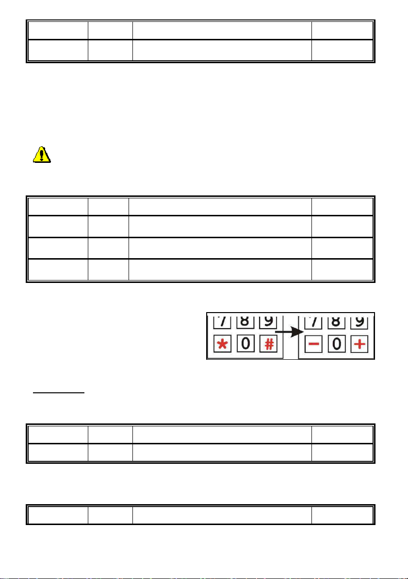
Parameter Value Meaning Basic
6* t
Delayed start for no-Urmet switchboards
with line testing (0/1)
0
This function is off as standard t=0. By switching this function on t=1 the processor goes
into sleep mode immediately after the line connection, and after 3 secs. The combiphone
initialises. The line connection after the power supply connection is then delayed - state
switching on/restarting of the switchboard. If this function is not working and the telephone
switchboard still identifies a line fault, then there is no other option but to use an internal
power supply, by switching over DIP switch 3 and 4 to "on".
5.6 Parameter setting Hands Free
Hands Free parameter setting must be changed only by qualified staff
First ensure that the rubber seal on the microphone fits properly, otherwise setting the
acoustic parameters will be difficult.
Parameter Value Meaning Basic
71 gg
72 ff
73 rr
Reception volume 01-16 (16 is the
highest) (SPK)
Transmission volume 01-16 (16 is the
highest) (MIC)
Speaker volume 01-16 (16 is the
highest) (TRH)
07
07
07
gg/ff/rr Each number is entered as 2 digits with a range 01-16. After receiving a
confirmation tone ♫ the new value is immediately active and can be tested.
Stops for the maximum and minimum
volume are acoustically signalled (3 tones
like the signal for the end of a call). If you
don’t press anything for 5 seconds then
the ‘set value’ is saved and you hear a
confirmation tone ♫.
WARNING !! Default values are set by the manufacturer and it is not recommended that
you change them unless absolutely necessary.
Parameter Value Meaning Basic
74 c
Soft transition of switch over (0/1) 1
By default this function is set to ON (c=1), it is a character of the semi-duplex operation
switch over on the telephone line. If the character of silencing is too steep, it is possible to
soften it using c=0.
Parameter Value Meaning Basic
DS1148-014D 35
Page 36
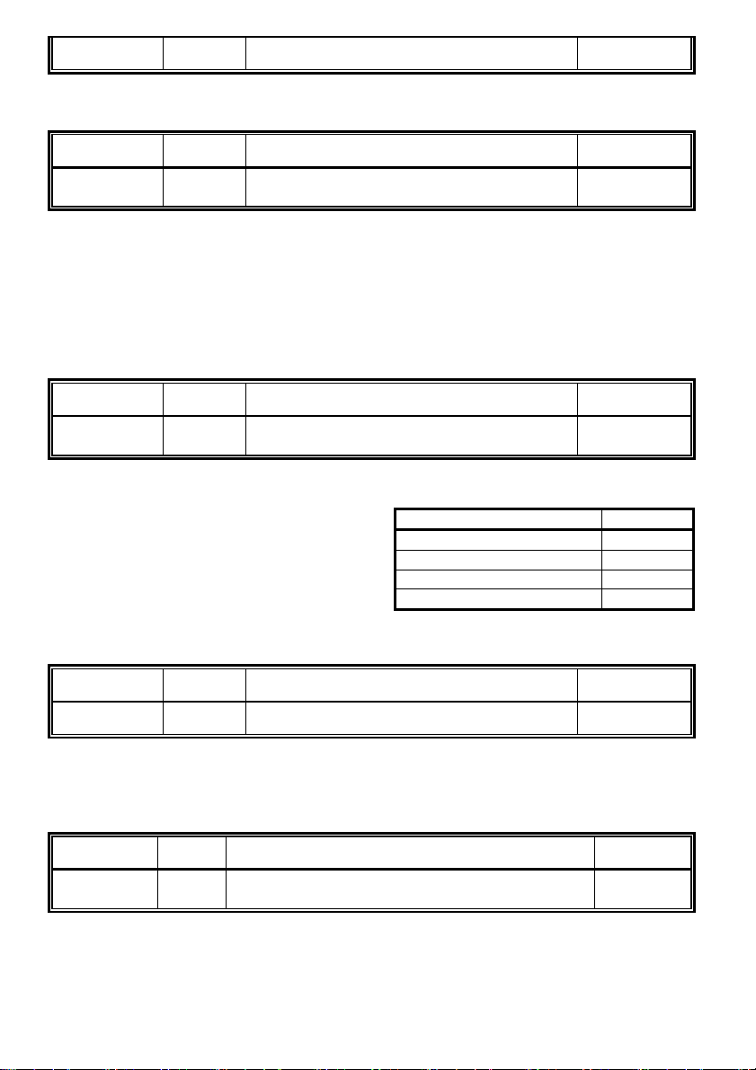
75 n
s
Suppression of background noise (0/1) 1
By default this function is set to ON (n=1), suitable for noisy location. This is related to
setting of parameters 71, 76, 77.
Parameter Value Meaning Basic
76 b
Threshold for switching on the microphone
1-4 (4 is the highest)
2
There is a simultaneous signal from the microphone and the speaker on the telephone
line, to ensure that the combiphone doesn’t produce acoustic feedback. In the Hands Free
circuit there are several functioning blocks for supressing this feedback. The basic one is
a circuit for semi-duplex operation, where the incoming signal weakens the microphone
and the signal from the microphone weakens the incoming signal. Thresholds for
switching on the microphone are set in this parameter, the lower the value the higher the
sensitivity of the microphone. In noisy surroundings it is recommended to use a higher
value with combination of parameters 71,75, 77.
Parameter Value Meaning Basic
77 s
Speed of switching over voice atomisation
1-4 (4 is the slowest)
2
Parameters 75, 76 describes the principle of acoustic feedback and the speed with which
the circuit switches over, the quality of incoming or outgoing sounds are set with
parameter 77.
Switchover time [ms]
1 1
2 2
4 3
8 4
- choice
Parameter Value Meaning Basic
78 l
VA characteristic for line connection (0/1) 1
Nearly every country in the world has different telephone norms and this parameter
enables you to lower the voltage on the combiphone terminals to connect telephone line
voltages in active state by 1V. Where it is required the respective norm I=0 lowers line
voltage by 1V, as standard it is l=1.
Parameter Value Meaning Basic
79 k
Compensation for loss of conduit depending on
line current (0/1/2)
1
The combiphone has a circuit for installations remote from the switchboard (>100m) that
can compensate for the loss caused by a conduit. This function is switched off as
36 DS1148-014D
Page 37

standard k=0, but it is possible to set on 2 levels, depending on the current that
k
switchboard can supply (short circuit current I0).
Switchboard current I
0
- choice
Function off 0
20mA-50mA 1
45mA-75mA 2
Parameter Value Meaning Basic
70 uu
Level of signal transmission v [-dBm] (04-16) 10
uu The signal transmission range to the line is -4 to -16dBm, entered is required
level, which is uu=04 is -4dBm, uu=10 is -10dBm ...
DS1148-014D 37
Page 38
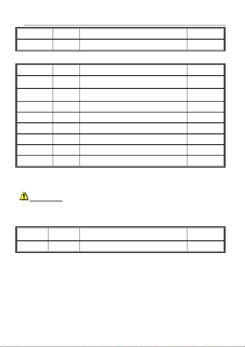
6 Basic setting and parameters Reset
Paramete
Parameter Value Meaning Basic
8# #
Basic setting provide
This setting does not affect parameters 1 and 2 (numbers saved in memory)
Parameter Value Meaning Basic
81
82
83
84
85
86
87
80
Deletes all numbers in 1st group
(Day mode)
Deletes all numbers in 2nd group
(Night mode)
Basic setting only for parameters 3x only 3..
Basic setting only for parameters 4x only 4..
Basic setting only for parameters 5x only 5..
Basic setting only for parameters 6x only 6..
Basic setting only for parameters 7x only 7..
Basic setting only for parameters 0x only 0..
Parameters 81 and 82 deletes all numbers saved in the button memory.
Parameters 83 – 87,80 deletes selective basic setting for parameters starting with
3,4,5,6,7,0. Values for the basic setting are stated for each parameter in the right hand column "Basic".
WARNING !!! deletion is irreversible and it would be necessary to programme them
again!
6.1 End of programming
r
9
Value Meaning Basic
END of programming
After choosing 9 programming tone from the keyboard telephone used for the
programming, the combiphone disconnects.
38 DS1148-014D
Page 39
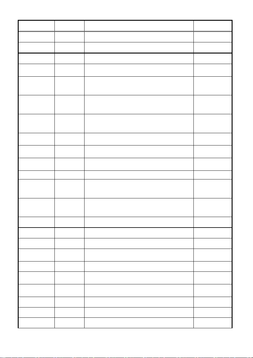
6.2 Parameter overview
DAY + NIGHT
hh...
DAY password
hh.
..
NIGHT
hh...
r,
DAY
NIGHT
Parameter Value Meaning Basic
1 tt nn… number nn under button tt
2 tt nn… number nn under button tt
31 r m relay r works in m (1-8) mode
31 r* tt
32 rp hh...
button tt causes switching on of relay r in
m=6 mode (01-99)
In
mode password
for
relay r, in order p=1-5, for 1 impulse and
p=* for 2 impulses (00-999999)
33 rp hh...
In
for relay r, in order p=1-5, for 1 impulse
mode password
and p=* for 2 impulses (00-999999)
34 rp hh...
In
in order p=1-5, for 1 impulse and p=* for 2
mode password
for relay
impulses (00-999999)
35 r aa
36 r cc
37 r ss
command aa from the phone for switching
on relay r 1 impulse (00-99,*0-*9)
command aa from the phone for switching
on relay r 2 impulses (00-99,*0-*9)
time ss [sec] of relay r switch on for time
t1/t4 (01-99)
38 r p Control of relay r during incoming call (0/1)
period xx [sec] between switching on of
39 xx
relays 1 and 2 in m=5 mode – time length
t3 (01-99)
period zz [sec] between impulses for
30 r zz
switching on 2 impulses of relay r – time
length t2/t5 (01-99)
3* r e Exit button for relay r (0/1/2)
-
-
11 21
01
-
-
-
155 266
150 260
105 205
11 21
10
105 205
10 20
41 v Type of choice v – ton/impulse (0/1)
42 z
43 g bb
44 xxxx
45 dd
46 nn
47 e
48 c
49 o
DS1148-014D 39
0
Sign for call prolonging (* / #) *
Command for combiphone disconnection
from the phone (00-99,*0-*9)
155 266
Service password (0000-9999) 0000
Command for switch over to
(00-99,*0-*9)
Command for switch over to
(0099,*0-*9)
11
10
System choice mode (0/1) 1
Keyboard connection (0-8) 0
Keyboard mode (0/1) 0
Page 40
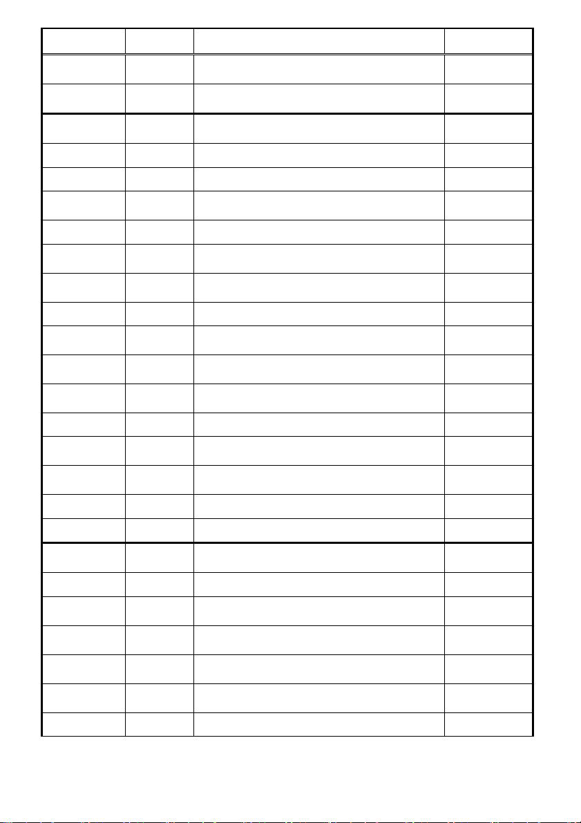
Parameter Value Meaning Basic
for permanent tone
40 d
4* k
51 q
52 d
Choice DTMF from the keyboard during a
call (0-3)
Line disconnection by repeat press of the
same button (0/1)
Number of rings before the combiphone
picks up (1-9)
Maximum length of call (0-9,*,#) 2
0
1
2
53 w
54 z
55 z
56 hh
500 x
501 y
502 z
503 tt
504 mm
505 f
506 p
507 uu
508 p
509 S
61 z
62 v
63 u
64 w
65 z
66 i
67 b
Time between button presses (1-9) 2
Time of disconnection for repeat choice
(1-5)
2
Time before choice begins (1-5) 1
Number of rings before disconnection
(04-99)
Medium frequency of tone detector (1-0)
12
3 (375475Hz)
Number of busy tones (2-0) 4
Length of time
(1-5)
Length of time for DTMF (tone) choice
(04-16)
Length of time for gap between DTMF
tones (04-16)
3 (3s)
10 (100ms)
10 (100ms)
Length of time Flash (1-6) 1 (100ms)
Length of time for pause/inter-digit gap
(1-0)
Level of transmission of DTMF choice uu
[-dBm] (04-16)
4 (800ms)
10
Pre-emphase DTMF (0/1) 0
Listening in DTMF – level (1-4) 2
Acoustic signalisation (confirmation, error,
empty memory, end of call...) (0/1)
1
Acoustic signalisation Intro/Concl. (0/1) 2
Acoustic signalisation ticking into a call
(0/1)
Internal power supply from connected
supply 12V (DIP 3,4) (0/1)
Acoustic signalisation for relay switch on
(0/1)
Suppression of reception DTMF from
microphone (0/1)
0
0
0
0
Signalization of not set button (0/1) 0
40 DS1148-014D
Page 41
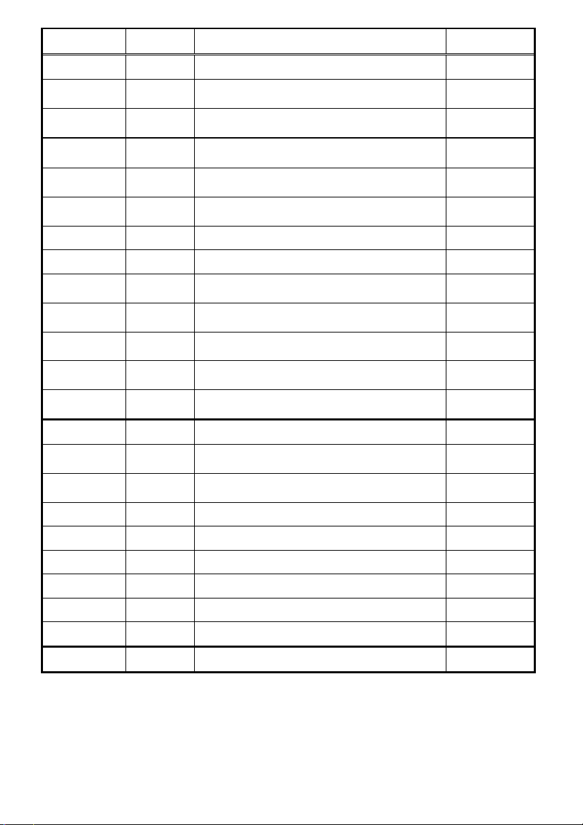
Parameter Value Meaning Basic
Transmission volume
68 b
6# s
6* t
71 gg
72 ff
73 rr
74 c
75 n
76 b
77 s
78 l
79 k
70 uu
8# #
81
82
83
Mute at the lock activated (0/1) 0
Setting of number of buttons on the main
panel
Delayed start for switchboards with line
tests (Siemens) (0/1)
Reception volume 01-16 (16 is the
highest) (SPK)
01-16 (16 is the highest) (MIC)
Speaker volume 01-16 (16 is the
highest) (TRH)
2
0
07
07
07
Soft transition of switchover (0/1) 1
Suppression of background noise (0/1) 1
Threshold for switching on the microphone
1-4 (4 is the highest)
Speed of switching over voice atomisation
1-4 (is the slowest)
VA characteristic for line connection
(0/1)
Compensation for loss of conduit
depending on line current (0/1/2)
Level of signalisation transmission
in [-dBm] (04-16)
2
2
1
1
10
Basic setting provide
Deletes all numbers in 1st group
(Day mode)
Deletes all numbers in 2nd group
(Night mode)
Basic setting only for parameters 3x only 3..
84
85
86
87
80
9
DS1148-014D 41
Basic setting only for parameters 4x only 4..
Basic setting only for parameters 5x only 5..
Basic setting only for parameters 6x only 6..
Basic setting only for parameters 7x only 7..
Basic setting only for parameters 0x only 0..
END of programming
Page 42
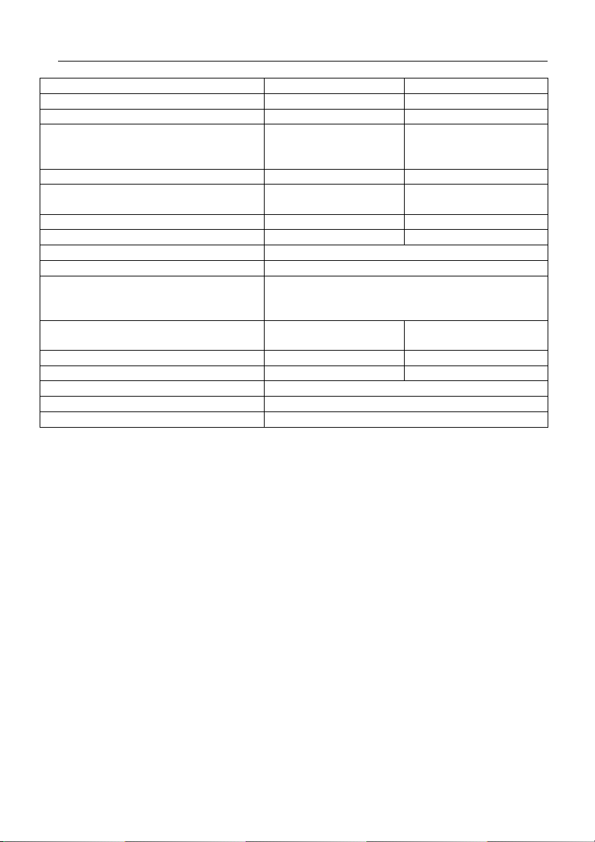
7 Technical parameters
Parameter
Value
Conditions
Minimum line current 18mA Line picked up
Minimum line voltage 18V Line disconnected
Voltage on the line when the
combiphone picks up (VA
characteristic)
Lead in in disconnected state < 30uA U = 60V
Impedance of line ending
Bandwidth 300Hz – 3400 Hz 20 - 60mA
Impendence of ringing > 2Kohm 25 – 60 Hz
Sensitivity of ringing detector min. 10 – 25 V
Impulse choice 40 / 60 ms
Power supply for name tag back
lighting, relay, heating and current
circuit for exit button
Max off take of backlighting and
heating
Max. Voltage of relay contact 48V When I < 1A
Max. Current of relay contact 1,5A When U < 30 V
Operating temperature - 20 to + 60 st.
Level of cover IP45
Weight Depends on variation and composition
< 8V
< 12V
220R +
820R paral. 115nF
Urmet: Ref. 9000/230
250mA 12Vss
I = 20mA
I = 60 mA
Line picked up
42 DS1148-014D
Page 43
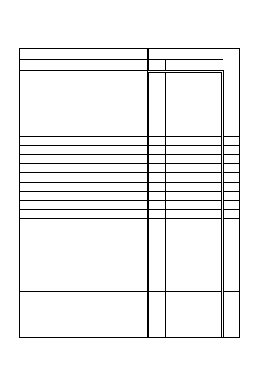
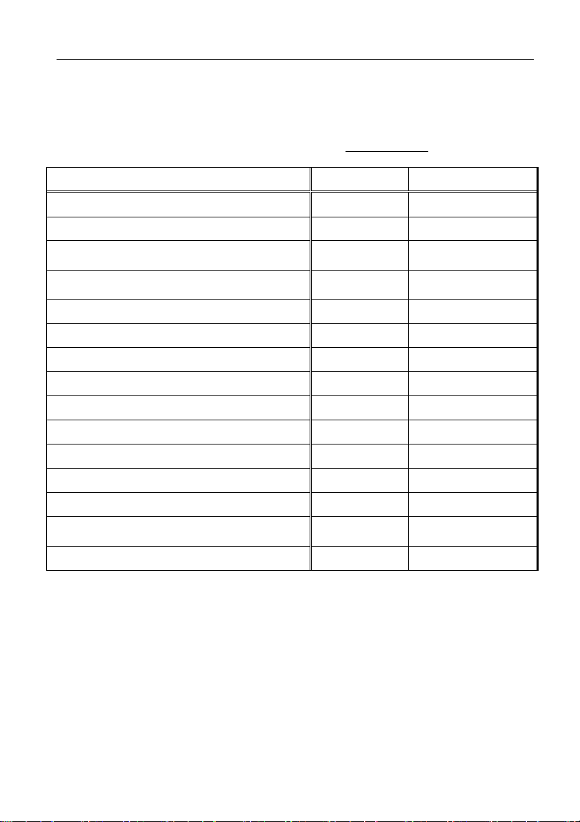
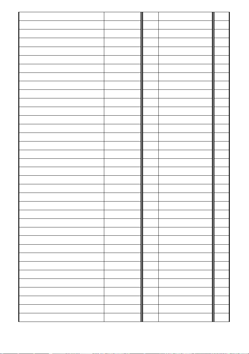
8 Table for easy programming
Fill in the values you want to programme into the empty part of the table, in the
double framed part there are whole programming commands to make programming
easier. You can keep the programmed values in the manual for future changes.
Meaning Programming sequence
description specify par. Fill the values
N° of
Digits
Number under button 1
Number under button 2
Number under button 3
Number under button 4
Number under button 5
Number under button 6
Number under button 7
Number under button 8
Number under button 9
Number under button 10
Number under button 11
Number under button 12
Number under button 1
Number under button 2
Number under button 3
Number under button 4
Number under button 5
Number under button 6
Number under button 7
Number under button 8
Number under button 9
Number under button 10
Number under button 11
Number under button 12
Relay 1 works in mode
Relay 2 works in mode
Passw. for relay 1 (1 imp.)
Passw. for relay 1 (1 imp.)
Passw. for relay 1 (1 imp.)
DS1148-014D 43
Day/1° group
Day/1° group
Day/1° group
Day/1° group
Day/1° group
Day/1° group
Day/1° group
Day/1° group
Day/1° group
Day/1° group
Day/1° group
Day/1° group
Night/2° gr.
Night/2° gr.
Night/2° gr.
Night/2° gr.
Night/2° gr.
Night/2° gr.
Night/2° gr.
Night/2° gr.
Night/2° gr.
Night/2° gr.
Night/2° gr.
Night/2° gr.
m=1 - 8
m=1 - 8
Day+Night
Day+Night
Day+Night
101
24
102
24
103
24
104
24
105
24
106
24
107
24
108
24
109
24
110
24
111
24
112
24
201
24
202
24
203
24
204
24
205
24
206
24
207
24
208
24
209
24
210
24
211
24
212
24
311
1
312
1
3211
6
3212
6
3213
6
Page 44
Passw. for relay 1 (1 imp.)
Passw. for relay 1 (1 imp.)
Passw. for relay 1 (2 imp.)
Passw. for relay 2 (1 imp.)
Passw. for relay 2 (1 imp.)
Passw. for relay 2 (1 imp.)
Passw. for relay 2 (1 imp.)
Passw. for relay 2 (1 imp.)
Passw. for relay 2 (2 imp.)
Passw. for relay 1 (1 imp.)
Passw. for relay 1 (1 imp.)
Passw. for relay 1 (1 imp.)
Passw. for relay 1 (1 imp.)
Passw. for relay 1 (1 imp.)
Passw. for relay 1 (2 imp.)
Passw. for relay 2 (1 imp.)
Passw. for relay 2 (1 imp.)
Passw. for relay 2 (1 imp.)
Passw. for relay 2 (1 imp.)
Passw. for relay 2 (1 imp.)
Passw. for relay 2 (2 imp.)
Passw. for relay 1 (1 imp.)
Passw. for relay 1 (1 imp.)
Passw. for relay 1 (1 imp.)
Passw. for relay 1 (1 imp.)
Passw. for relay 1 (1 imp.)
Passw. for relay 1 (2 imp.)
Passw. for relay 2 (1 imp.)
Passw. for relay 2 (1 imp.)
Passw. for relay 2 (1 imp.)
Passw. for relay 2 (1 imp.)
Passw. for relay 2 (1 imp.)
Passw. for relay 2 (2 imp.)
Day+Night
Day+Night
Day+Night
Day+Night
Day+Night
Day+Night
Day+Night
Day+Night
Day+Night
Day
Day
Day
Day
Day
Day
Day
Day
Day
Day
Day
Day
Night
Night
Night
Night
Night
Night
Night
Night
Night
Night
Night
Night
Button choice for 1 relay m=6
Button choice for 2 relay m=6
Switch on r 1 from phone
1 impulse
3214
6
3215
6
321*
6
3221
6
3222
6
3223
6
3224
6
3225
6
322*
6
3311
6
3312
6
3313
6
3314
6
3315
6
331*
6
3321
6
3322
6
3323
6
3324
6
3325
6
332*
6
3411
6
3412
6
3413
6
3414
6
3415
6
341*
6
3421
6
3422
6
3423
6
3424
6
3425
6
342*
6
311*
2
312*
2
351
2
44 DS1148-014D
Page 45
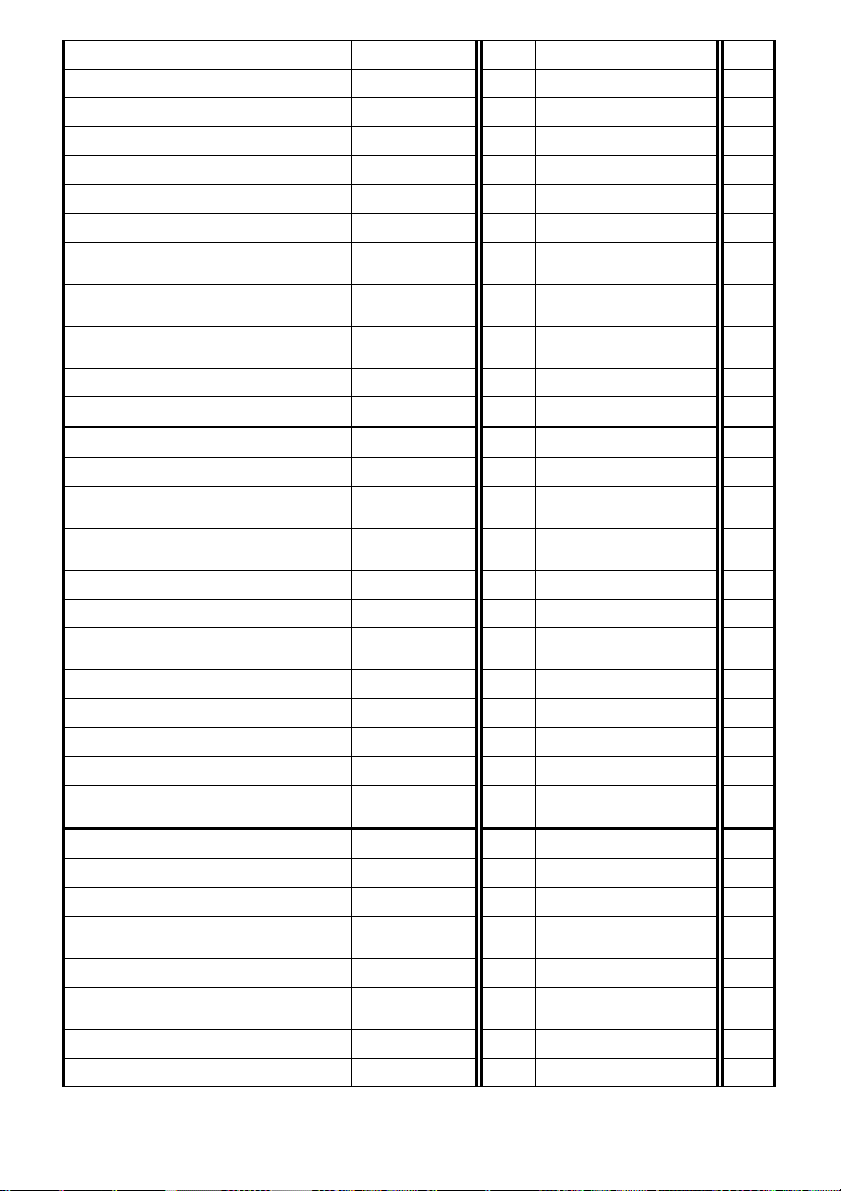
Switch on r 2 from phone
Length of time between switch on r
Length of time between impulses
Length of time between impulses
Disconnection by repeat press of
Time of disconnection for repeat
Number of rings before
Switch on r 1 from phone
Switch on r 2 from phone
Length of time for r 1 switch on
Length of time for r 2 switch on
Control of r 1 during incoming call
Control of r 2 during incoming call
1 impulse
2 impulses
2 impulses
[sec]
[sec]
1 / 0
1 / 0
352
2
361
2
362
2
371
2
372
2
381
1
382
1
1 and 2
of r 1
of r 2
Exit button for r 1
Exit button for r 2
[sec]
[sec]
[sec]
0/1/2
0/1/2
Type of choice tone / imp. 0 / 1
Sign for prolonging of call * / #
Combiphone disconnection from
the phone
Combiphone disconnection from
the phone
431
432
Service password
Command for switch over to DAY
Command for switch over to
NIGHT
System choice mode 1 / 0
Keyboard connection 0/1-8
Keyboard mode 1 / 0
choice DTMF from keyboard 0/1/2/3
the same button
0 / 1
Number of rings for pick up
Maximum length of time [min]
Time between button presses [sec]
39
2
301
2
302
2
3*1
1
3*2
1
41
1
42
1
2
2
44
4
45
2
46
2
47
1
48
1
49
1
40
1
4*
1
51
1
52
1
53
1
choice
Time before choice commences [sec]
disconnection
Frequency of tone detector table
Number of busy tones
DS1148-014D 45
[sec]
54
1
55
1
56
2
500
ms 1
501
1
Page 46
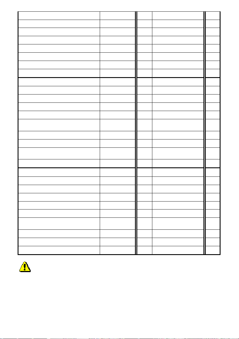
Length of time of permanent tone
Suppression of reception from
)
Suppression of background noise
Speed of switching over voice
Length of time of tone choice nn x 10
Gap between DTMF tones nn x 10
Length of time Flash n x 100
Length of time of pause / gap n x100+400
Transmitting level DTMF 04-16
preemphase DTMF 0 / 1
Listening in DTMF - level 1-4
Acoustic signalisation (other) 0 / 1
Acoustic signalisation Intro/Concl. 0 / 1
Acoustic sign. ticking 0 / 1
Internal power supply from 12V 0 / 1
Signal tone turning on relay 0 / 1
502
sec 2
503
ms 2
504
ms 2
505
ms 1
506
ms 1
507
-dBm 2
508
1
509
1
61
1
62
1
63
1
64
1
65
1
microphone
0 /1
Signalization of not set button 0 / 1
Mute at the lock activated 0 / 1
N° of buttons on the panel
Delayed start (i.e non Urmet pabx
Type
dependant
Reception volume (TRH) 01-16
Transmitting volume (MIC) 01-16
Speaker volume (SPK) 01-16
Soft transition of switch over 0 / 1
0 / 1
microphone switch on threshold 1 - 4
atomization
1 - 4
VA characteristic 0 / 1
Compensation for loss of conduit 0 / 1 / 2
Level of signalisation transmission 04 - 16
66
1
67
1
68
1
6#
1
6*
1
71
2
72
2
73
2
74
1
75
1
76
1
77
1
78
1
79
1
70
-dBm 2
WARNING !!! Parameters from 70 to 79 must be modified only by qualified
staff.
46 DS1148-014D
Page 47
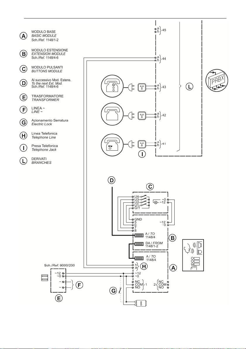
9 Basic connection diagram
DS1148-014D 47
Page 48

DS1148-014D
URME T S.p.A.
10154 TORI NO (ITALY)
VIA BOLOG NA 18 8/C
Telef. +39. 011.24.00.000 (R IC.AU T.)
Fax +3 9. 011.24.00.30 0 - 32 3
48 DS1148-014D
Technical Assistance Custo mer Servic e
+39. 0 11.23.39.810
http:// www. urmet. com
e-mail: info@urme t.com
Prodotto nella Repubblica Ceca su specifica URMET
Made in Czech Republic to URMET specification
 Loading...