

Page 1

sec.4c
−−−−
1
2GO! - Technical manual
ACCESSORIES
SECTION 4C
SPECIAL DECODING Ref. 1082/80 2
SPECIFICATION ............................................................................... 2
TECHNICAL SPECIFICATIONS ........................................................2
DEFAULT CONFIGURATION ...........................................................2
INSTALLATION ................................................................................2
PROGRAMMING .............................................................................. 3
Switching mode ............................................................................3
Operating mode ............................................................................3
CONFIGURATION AND OPERATION SUMMARY TABLE ............... 7
WIRELESS CALL REPEATER Ref. 4311/13 8
TECHNICAL FEAUTURES ................................................................ 8
INSTALLATION ................................................................................8
Wiring diagram .............................................................................8
VIDEO MEMORY MODULE Ref. 1082/88 9
TECHNICAL FEAUTURES ................................................................ 9
INSTALLATION ................................................................................9
Description of terminals ..............................................................10
OPERATION ................................................................................... 10
Recording fi lms ...........................................................................10
Film playback .............................................................................10
Download from www.urmetdomus.com Technical Manuals area.
SECTION CONTENTS
Some products may be described in the “New” section.§
GPRS MODEM Ref. 1082/52 11
PROGRAMMING THE MMS MESSAGING PARAMETERS ...........11
PROGRAMMING THE ACCESS PASSWORD
AND MMS MESSAGING NUMBER (TEL1) .....................................11
PROGRAMMING THE MODEM CONNECTION
PARAMETERS FOR CONNECTING
TO THE CELL PHONE NETWORK ................................................. 11
MMS Messaging activation ............................................................ 11
SUPPLEMENTARY THREE-TONE RINGING Ref. 1072/59 12
4+N INTERFACE FOR 2GO! Ref. 1082/67 12
SPECIFICATIONS ...........................................................................12
INSTALLATION ...............................................................................13
Description of terminals ..............................................................13
PROGRAMMING ............................................................................ 13
Line terminal settings .................................................................13
CONFIGURATION .......................................................................... 13
User code ...................................................................................13
Indoor station code ....................................................................13
Page 2

ACCESSORIES
2
−−−−
sec.4c
2GO! - Technical manual
TECHNICAL SPECIFICATIONS
Temperature: -5°C +45°C
C, NC, NA exchange contact: 30Vdc 5A
250Vac 5A
Monostable relay activation time: adjustable from 1 second
from 10 minutes ±5%
DEFAULT CONFIGURATION
The special decoder default settings are:
PE dip switch: all ON
INF dip switch: all OFF (INF=0)
SUP dip switch: all ON (SUP=31)
M/T dip switch: OFF (monostable)
COD dip switch: OFF (operation not following calls)
programmed event: staircase lights button
Timer: 1”
Line terminal: ON
INSTALLATION
The special decoder must be considered in the total apartment
station count. Therefore, the number of apartment stations (video
door phones + door phones + PABX interfaces + special decoders)
MUST NOT exceed 32. Up to 4 special decoders can be installed in
the entire system.
The special decoder can be installed in an electrical panel on a DIN
bar (it occupies six 18 mm DIN modules) or wall-mounted using bolts
(not provided). Terminal boards, confi guration dip switches and other
settings must be accessed when the electrical panel is open.
For connecting the remote button (PC terminals) use wires of
minimum cross-section area 0.22mm2 with a maximum distance
of 25m.
DESCRIPTION OF TERMINALS
NA Electrical load activation relay normally open contact
NC Electrical load activation relay normally closed contact
C Electrical load activation relay contact common
LINE }
Non-polarised bus line
LINE
PC
}
Remote button connection terminals
PC
§
SPECIAL DECODING Ref. 1082/80
ON
PE
NA
INF SUP
COD M/T
PROG
TIMER
OFF=M
ON=T
ON
ON
1
23
Sch.1082/80
NC
C
Z
PC
LINE
61 mm
108 mm
(6 DIN modules)
90 mm
The Ref. 1082/80 special decoder is used in 2GO! systems to operate
electrical loads thanks to a relay with 230Vca 5A contact via controls
sent by users through apartment stations or door units in the system.
The main applications are:
Opening garage doors.
Switching staircase lights on.
Switching electrical loads on and off.
SPECIFICATION
The main features are:
Monostable (programmable activation time from 1 second to 10
minutes) or toggle operation.
Possibility of call code activation (from apartment station or
intercom) or alternatively via other system events.
Possibility of connecting a remote activating button (monostable
or toggle).
System programming/failure LED.
Possibility of connecting to system in in/out mode or via Ref.
1082/51 distributor.
ON DIP
4321 5
ON
321
ON
21
ON DIP
4321 5
ON
PENAINF SUP COD M/T PROG TIMER
OFF=M
ON=T
ON
ON
Sch.1082/80
NC C
Z
PCLINE
1
7 6
2 3
5 4
1
Confi guration dip switch
2
Programming button and LED
3
Timer adjustment trimmer
4
Remote button connection terminals
5
Line connection terminals
6
Line terminal
7
Electrical load activation relay contact terminals
•
•
•
•
•
•
•
•
SPECIAL DECODING Ref. 1082/80
SPECIAL DECODING Ref. 1082/80
SPECIFICATION - TECHNICAL SPECIFICATIONS
DEFAULT CONFIGURATION - INSTALLATION
Page 3

ACCESSORIES
sec.4c
−−−−
3
2GO! - Technical manual
PROGRAMMING
ON
=
OFF
=
ON
ON
SWITCHING MODE
Firstly, defi ne whether the relay must be controlled in monostable or
toggle mode.
In monostable mode, when an appropriate command is received or
the remote button connected to the PC terminals is pressed, the relay
will be energised for a variable time from 1 second to 10 minutes
according to the setting made using the “timer” trimmer.
In toggle mode, when an appropriate command is received or the
remote button connected to the PC terminals is pressed, the relay will
switch and the trimmer setting will be ignored. The relay will remain
switched until a new command is reached.
ON DIP
4321 5ON321
ON
21
ON
21
ON DIP
4321 5
Toggle
Monostable
ON
PENAINF SUP COD M/T PROG TIMER
OFF=M
ON=T
ON
ON
Sch.1082/80
NC C
Z
PCLINE
To test the operation time in monostable mode, simply short circuit
the PC terminals provisionally and check the relay energising time.
OPERATING MODE
The special decoder can be confi gured to be activated by a call (from
a door or intercom unit) by a user code (from 0 to 31) if this is not
already used by apartment stations. Alternatively, it can be activated
by other system events (pressing a door opening button on an
apartment station, pressing the call to switchboard button, pressing
the staircase light button on an apartment station or door unit).
A - OPERATION FOLLOWING A CALL
The position of the PE dip switch is ignored:
ON DIP
4321 5ON321
ON
21
ON DIP
4321 5
ON
PENAINF SUP COD M/T PROG TIMER
OFF=M
ON=T
ON
ON
Sch.1082/80
NC C
Z
PCLINE
ON
321
Arrange the COD dip switch in the on position:
ON DIP
4321 5ON321
ON
21
ON DIP
4321 5
ON
PENAINF SUP COD M/T PROG TIMER
OFF=M
ON=T
ON
ON
Sch.1082/80
NC C
Z
PCLINE
ON
12
At this point, assign a user code from 0 to 31 to the special decoder.
To do this, set the INF and SUP dip switches to the same value as
the user code chosen using the following table. This code must not
correspond to another user code in the system.
INF/SUP= 6
43215
INF/SUP= 5
43215
INF/SUP= 4
43215
INF/SUP= 7
43215
INF/SUP= 10
43215
INF/SUP= 9
43215
INF/SUP= 8
43215
INF/SUP= 11
43215
INF/SUP= 14
43215
INF/SUP= 13
43215
INF/SUP= 12
43215
INF/SUP= 15
43215
INF/SUP= 18
43215
INF/SUP= 17
43215
INF/SUP= 16
43215
INF/SUP= 19
43215
INF/SUP= 22
43215
INF/SUP= 21
43215
INF/SUP= 20
43215
INF/SUP= 23
43215
INF/SUP= 26
43215
INF/SUP= 25
43215
INF/SUP= 24
43215
INF/SUP= 27
43215
INF/SUP= 2
43215
INF/SUP= 1
43215
INF/SUP= 0
43215
INF/SUP= 3
43215
INF/SUP= 30
43215
INF/SUP= 29
43215
INF/SUP= 28
43215
INF/SUP= 31
43215
At this point, the special decoder is ready to be activated by door
units by means of the programmed call code.
To be activated from an apartment station, the special decoder call
codes must be programmed for all apartment stations which need to
access the service as follows:
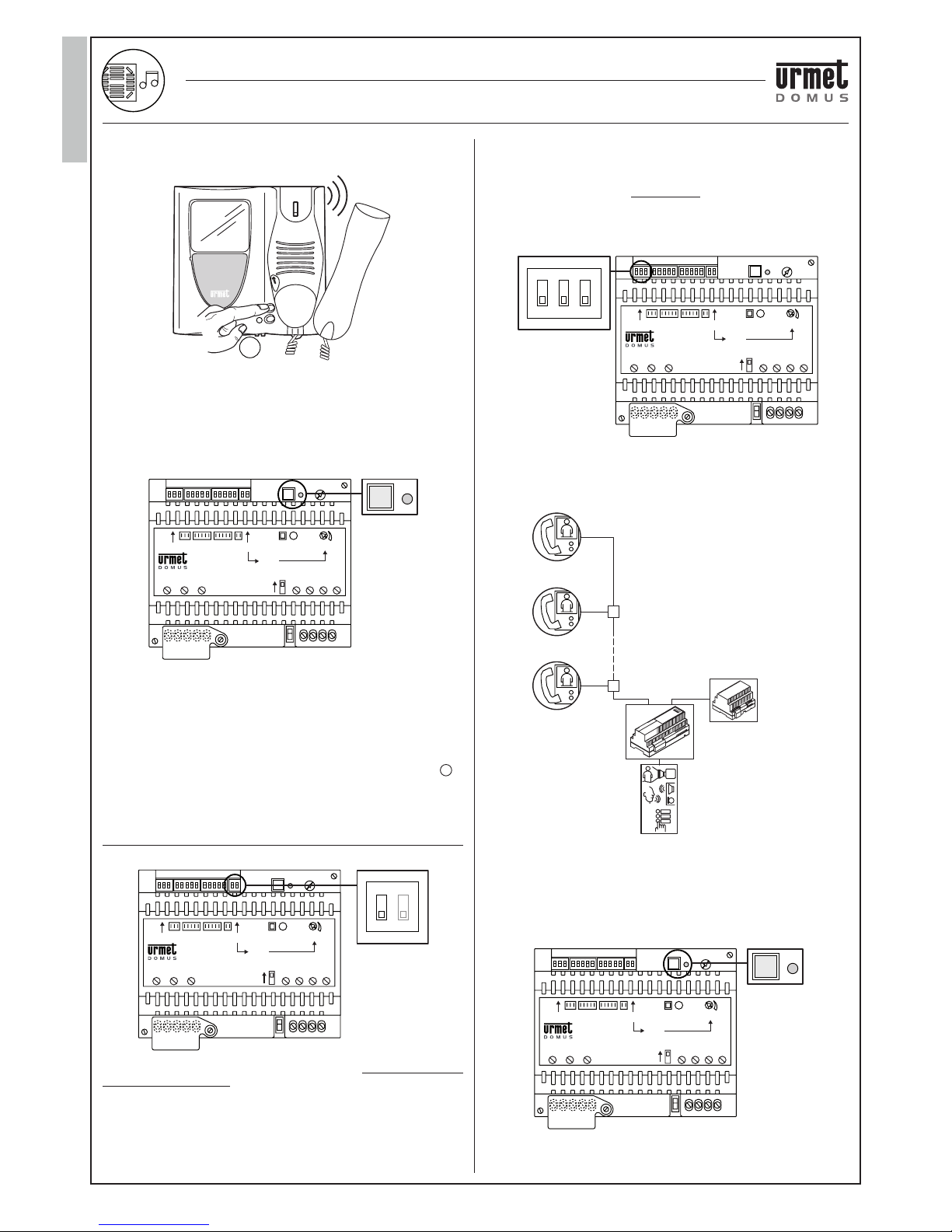
1. Go to the apartment station to be programmed.
2. Hold the door opener button pressed and pick up the handset. The
apartment station outputs a tone to indicate that programming is
in progress.
BEE
P
1
2
SPECIAL DECODING Ref. 1082/80
PROGRAMMING
SPECIAL DECODING Ref. 1082/80
Page 4
ACCESSORIES
4
−−−−
sec.4c
2GO! - Technical manual
3. Press the button to be programmed. The door unit will output a
confi rmation tone.
BEEP
3
For buttons meaning, refer to “button function table” in section
1.
On Folio video door phones, the decoder code must be added
to the directory and calls must be made to that code.
4. Go to the special decoder and press the programming button.
The special decoder LED will blink four times and the apartment
station will beep to indicate that programming is over.
ON DIP
4321 5ON321
ON
21
ON DIP
4321 5
ON
PENAINF SUP COD M/T PROG TIMER
OFF=M
ON=T
ON
ON
Sch.1082/80
NC C
Z
PCLINE
5. Hook up the handset of apartment station. It will beep to indicate
exit from programming mode.
6. Check programmed function: Pick up the handset, press the
programmed button and then check that the special decoder
service is activated.
7. Hang up.
The auto-on and video switching functions will not be lost if is
programmed for the special decoder call function because these
are available when the handset is off-hook.
B - OPERATION FOLLOWING OTHER EVENTS
Arrange the COD dip switch in the off position:
ON DIP
4321 5ON321
ON
21
ON
12
ON DIP
4321 5
ON
PENAINF SUP COD M/T PROG TIMER
OFF=M
ON=T
ON
ON
Sch.1082/80
NC C
Z
PCLINE
In this way, the special decoder can be activated alternatively by one
of the following 3 events:
1. Pressure of the door opening button on an apartment station.
2. Pressure of the switchboard calling button on an apartment
station.
3. Pressure of the staircase light button on an apartment station
and/or door unit.
§
§
1. Operation following pressure of the door opening button on
an apartment station
This service can be activated by pressing on an apartment station
the door opener button in any instant, also not following reception
of a call.
The PE dip switches may be arranged in any position but the COD
switch must be OFF:
ON DIP
4321 5ON321
ON21ON DIP
4321 5
ON
PENAINF SUP COD M/T PROG TIMER
OFF=M
ON=T
ON
ON
Sch.1082/80
NC C
Z
PCLINE
ON
321
At this point, the group of users which must activate the special
decoder by pressing the door opener button must be defi ned.
This group must coincide with the users comprised when the
code set in INF and that set in SUP.
1
2
3
4
LINE4
LINE3
LINE2
LINE1
LINE0
9
8
0
INF= 0
SUP= 8
Ref. 1082/80
TC
In the confi guration example shown, the users with code from 0
to 8 can switch the special decoder relay while this function is not
allowed to users with code 9.
The last operation is self-learning of the “door opener button
pressure” event. Press the special decoder programming button.
The LED will start blinking.
ON DIP
4321 5ON321
ON
21
ON DIP
4321 5
ON
PENAINF SUP COD M/T PROG TIMER
OFF=M
ON=T
ON
ON
Sch.1082/80
NC C
Z
PCLINE
SPECIAL DECODING Ref. 1082/80
SPECIAL DECODING Ref. 1082/80
PROGRAMMING
Page 5

ACCESSORIES
sec.4c
−−−−
5
2GO! - Technical manual
Go to any user and press the door opener button. The LED will go
out to indicate that programming is over.
2. Operation following pressure of the switchboard calling
button on an apartment station
The service can be activated by pressing the switchboard call
button on apartment stations with handset off-hook.
The apartment station switchboard call button / / on the
video door phone or 2 on the door phone can be used for this
function only when the handset is off-hook and not following a call
providing if was not programmed for the intercom call function.
If this button was programmed for intercom call functions, the
switchboard call function is lost. In this case, restore the bracket
default settings, program the intercom function on another button;
alternatively, activate the special decoder by means of another
event.
The PE dip switches may be arranged in any position but the COD
switch must be OFF:
ON DIP
4321 5ON321
ON
21
ON DIP
4321 5
ON
PENAINF SUP COD M/T PROG TIMER
OFF=M
ON=T
ON
ON
Sch.1082/80
NC C
Z
PCLINE
ON
321
At this point, the group of users which must activate the special
decoder by pressing the switchboard call button must be defi ned.
This group must coincide with the users comprised when the
code set in INF and that set in SUP.
1
2
3
4
LINE4
LINE3
LINE2
LINE1
LINE0
9
8
0
INF= 0
SUP= 8
Ref. 1082/80
TC
In the confi guration example shown, the users with code from 0
to 8 can switch the special decoder relay while this function is not
allowed to users with code 9.
The last operation is self-learning of the “switchboard call button
pressure” event. Press the special decoder programming button.
The LED will start blinking.
ON DIP
4321 5ON321
ON
21
ON DIP
4321 5
ON
PENAINF SUP COD M/T PROG TIMER
OFF=M
ON=T
ON
ON
Sch.1082/80
NC C
Z
PCLINE
Go to any user, pick up the hanset and press the switchboard call
button. The LED will go out to indicate that programming is over.
3. Operation following pressure of the staircase light button on
an apartment station and/or door unit
This service can be activated by pressing the staircase light
function button after receiving a call or during a conversation on
an apartment station.
The apartment station staircase light button is the / /
on the video door phone or 3 on the door phone. It assumes
this function only after receiving a call, in auto-on mode or in
audio mode. The service can also be activated by pressing the
programmed “staircase light” function button (see below) on
apartment stations.
The position of the PE dip switch is not relevant for operation
using an apartment station button but the COD switch must be
OFF:
ON DIP
4321 5ON321
ON21ON DIP
4321 5
ON
PENAINF SUP COD M/T PROG TIMER
OFF=M
ON=T
ON
ON
Sch.1082/80
NC C
Z
PCLINE
ON
321
At this point, the group of users which must activate the special
decoder by pressing the staircase light button must be defi ned.
This group must coincide with the users comprised when the
code set in INF and that set in SUP.
SPECIAL DECODING Ref. 1082/80
PROGRAMMING
SPECIAL DECODING Ref. 1082/80
Page 6

ACCESSORIES
6
−−−−
sec.4c
2GO! - Technical manual
1
2
3
4
LINE4
LINE3
LINE2
LINE1
LINE0
9
8
0
INF= 0
SUP= 8
Ref. 1082/80
TC
The last operation is self-learning of the “staircase light button
pressure” event. Press the special decoder programming button.
The LED will go on.
ON DIP
4321 5ON321
ON
21
ON DIP
4321 5
ON
PENAINF SUP COD M/T PROG TIMER
OFF=M
ON=T
ON
ON
Sch.1082/80
NC C
Z
PCLINE
Go to any user, request door unit auto power-on and press the
staircase light button.
The led will go out to indicate that programming is over.
The special decoder can be activated also by pressing the
apartment station staircase lights. Position the PE dip switches
corresponding to the codes of the apartment station that must
activate it to the ON position:
1
2
3
4
LINE4
LINE3
LINE2
LINE1
LINE0
Ref. 1082/80
ID= 2ID= 1 ID= 3
ON
32PE1
TC TC TC
In the confi guration example shown, the special decoder can be
activated by pressing the staircase light button of door units with
ID 1 and 3; it cannot be activated from door unit with ID = 2.
At this point, program a staircase light function for each door unit
which must activate the special decoder.
1. Set the dip switch ID to 0 to start programming the door unit. The
door unit will beep every fi ve seconds to indicate that programming
is in progress and the yellow LED will be on.
ID
12
ON
2. Hold the button to be assigned to the staircase light function
pressed. The door unit will beep when the button is pressed and
beep again after three seconds. Release the button immediately.
STAIRCASE LIGHTS
BEEP _ _ _ 3s _ _ _ BEE
P
3. Reposition the ID dip switches of the door unit in the correct
setting. The yellow LED of the door unit will go out.
4. At this point, run “staircase light button pressure” self-learning
unless this procedure has already been run on apartment
stations.
Press the special decoder programming button. The LED will go
on.
ON DIP
4321 5ON321
ON
21
ON DIP
4321 5
ON
PENAINF SUP COD M/T PROG TIMER
OFF=M
ON=T
ON
ON
Sch.1082/80
NC C
Z
PCLINE
SPECIAL DECODING Ref. 1082/80
SPECIAL DECODING Ref. 1082/80
PROGRAMMING
Page 7

ACCESSORIES
sec.4c
−−−−
7
2GO! - Technical manual
Go to the door unit and press the staircase light button. The
special decoder LED will go out to indicate that programming is
over.
If during programming, the button is held pressed for longer than
fi ve seconds, all optional programming of the apartment station
will be returned to default settings (last user code in column =
31; surveillance cameras = not present; staircase lights button =
not present). Programming will need to be repeated.
§
CONFIGURATION AND OPERATION SUMMARY TABLE
Configurations PE
2
Any
Any
Any
Any Any
Switch the
buttons
corresponding
to the apartment
stations which
must activate the
special decoder to
the on position
13
Program
a value from
1” to 10’ of
M/T= OFF
Program
a value from
1” to 10’ of
M/T= OFF
Program
a value from
1” to 10’ of
M/T= OFF
Program
a value from
1” to 10’ of
M/T= OFF
Program
a value from
1” to 10’ of
M/T= OFF
Any
Program UT
user code
from 0 to 31
(must be INF= SUP
and not be the same
as any other user
code
in the system)
Program
the user group
for activating
the special decoder
(must be
INF<= SUP)
Program
the user group
for activating
the special decoder
(must be
INF<= SUP)
Program
the user group
for activating
the special decoder
(must be
INF<= SUP)
1 2 3 4 5
INF
1 2 3 4 5
SUP
1
ON
OFF
OFF
OFF
COD
OFF
ON
2
OFF
ON
OFF
ON
OFF
ON
OFF
ON
M/T TIMER Other programming
Program the intercom code
on an apartment station button
for activating
the special decoder.
The apartment stations are
all enabled
to activate the specialdecoder
by pressing the user code
call button.
Run “door opener
button pressure”
self-learning procedure
on special decoder
Run “switchboard
call button pressure”
self-learning procedure
on special decoder
Run “staircase
lights button pressure”
self-learning procedure
on special decoder.
Program the staircase
light button
on apartment stations
which must activate
the special decoder
Call from user
to door unit
or intercom call
Pressure of the door
opening button
on an
apartment station
Pressure of the
switchboard
calling button
on an
apartment station
Pressure of the
staircase light
button on an
apartment station
and/or door unit
Pressure of the
special decoder
remote button
(PC terminals)
Activation
following:
SPECIAL DECODING Ref. 1082/80
CONFIGURATION AND OPERATION SUMMARY TABLE
SPECIAL DECODING Ref. 1082/80
Page 8

ACCESSORIES
8
−−−−
sec.4c
2GO! - Technical manual
WIRELESS CALL REPEATER Ref. 4311/13
The Ref. 4311/13 can be used to radio transmit the call signal from a
door phone system or video door phone system to a Mistral receiver.
The call repeater can be used in combination with the following
ringers:
Ringer with a range of up to 200m,
fl ash and powering by batteries or power supply unit Ref. 4311/2
Ringer with a range of up to 150m,
fl ash and 230Vac powering from the electricity mains Ref. 4311/3
Refer to the “Product Technical Manual - Door Phone and Video Door
Phone systems” for ringers, features and installation procedures.
The device is ready to be powered by a 9V battery (not included)
which ensures system operation also in unfavorable conditions. The
battery must be replaced approximately every two years or when the
device performance degrades.
TECHNICAL SPECIFICATIONS
Power: alkaline 6LR61 9V battery
Transmission frequency: 868,35MHz
Dimensions (L x H x P: 85 x 85 x 30mm
Working temperature range: +5 ÷ 40°C
INSTALLATION
Install the device away from sources of heat and in a place protected
from humidity and water sprays.
Be very careful when handling printed circuit components and
particularly the metallic antenna during installation and programming.
The metallic antenna must not be moved from its original position.
Before fi nal installation of the device, make a test call to check that the
radio signal is correctly picked up by the receiver.
Open the product using a screwdriver as a lever in the points shown
(A).
A
•
•
•
Using the bolts and holes provided (B), fasten when screws the
product near the door phone or in a position where the connection
wires of the device it can be intercepted
B
B
D C
Connect to the terminal board as shown in the system diagram
below. Do not disconnect the 2-way battery cable from the terminal
board.
Connect the battery (D).
The signal can be sent to the receiver during programming by
pressing the button (C) on the printed circuit. The indicator LED will
start blinking.
For programming the receiver, refer to the wireless ringer instruction
paragraph.
WIRING DIAGRAM
Ref.4311/13
Cm
C+
CS+
SS+
LINE
LINE
FROM RISER COLUMN
•
•
•
•
•
WIRELESS CALL REPEATER Ref. 4311/13
WIRELESS CALL REPEATER REF. 4311/13
TECHNICAL SPECIFICATIONS
INSTALLATION
Page 9

ACCESSORIES
sec.4c
−−−−
9
2GO! - Technical manual
VIDEO MEMORY MODULE Ref. 1082/88
SEGRETERIA
VIDEOCITOFONICA
Sch./Ref.
1082/88
180 mm
(10 DIN modules)
90 mm
55 mm
The Ref. 1082/88 video door phone answering machine (SVC for
short) is designed for 2GO! systems for storing fi lms of unanswered
calls recorded by a video door phone station.
In brief, the functions of the SVC include:
Centralised function: up to eight 7-second fi lms can be stored for
each user (up to 32) in the system.
Users can play and delete the fi lms by pressing the rhomboid
button on the video door phone.
Films can be sent as MMS messages by a Ref. 1082/52 GPRS
modem. This function is available for the one-family 2GO! kits only
and can be activated and deactivated by appropriately connecting
two dedicated terminals.
Date, time, and other diagnostic messages appear on a four-digit
display.
Three buttons for adjusting date and time and using other test
functions.
SEGRETERIA
VIDEOCITOFONICA
Sch./Ref.
1082/88
Display
Function
buttons
Transformer
(provided)
Serial
modem port
Line terminal
Led
3214
7658
TECHNICAL SPECIFICATIONS
Terminal power (0~, 12~): 13Vac ÷ 21Vac
15Vdc ÷ 28Vdc
Maximum terminal draw (0~, 12~): 350mAdc
Temperature: -5°C / +45°C
Memory capacity: 8 fi lms per user
7 seconds per fi lm
user manager
This is a class A device. The device can cause radio interference
in residential environments. The installer may need to take
appropriate measures in such a case.
•
•
•
•
•
§
INSTALLATION
For the installation are valid the generic rules of the 2GO! system.
Observe the following rules:
1. Maximum number of devices: Only one SVC can be installed
in a 2GO! system. This device is included in the TOTAL count of
2GO! devices. Possible system confi gurations:
3 door units, 1 SVC, 31 apartment stations, 31 distributors.
2 door units, 1 SVC, 32 apartment stations, 31 distributors.
2. Type of usable wires. The same distances for Atlantico video
door phone apartment stations using the same types of wire apply
for connecting the SVC to the system (LINE terminals). Refer to
the section 2.
3. Wiring and line terminals. The SVC can be connected in inout mode (Z terminal = OFF), via distributor (Z terminal = ON) or
directly to a power line (Z terminal = ON).
1
2
3
4
LINE4
LINE3
LINE2
LINE1
LINE0
Terminal
ON
Terminal
ON
Terminal
ON
3
2
14
7
6
5
8
TC
Terminal
OFF
Terminal
ON
1
2
3
4
LINE4
LINE3
LINE2
LINE1
LINE0
Terminal
ON
3
2
1
4
7
6
5
8
TC
1
2
3
4
LINE4
LINE3
LINE2
LINE1
LINE0
(IN/OUT
)
LINE
(DER)
LINE
ON
OFF
1082/51
PAT
ENTED
Terminal
ON
Terminal
ON
Terminal
ON
3
2
1
4
7
6
5
8
TC
Line terminal
ON
OFF
Z
4. Installation. The SVC can be installed in an electrical panel
on a DIN bar (it occupies ten 18mm DIN modules + two 18mm
DIN modules for the power transformer). Terminal boards and
confi guration dip switches are accessible with the electrical panel
open.
•
•
VIDEO MEMORY MODULE REF. 1082/88
TECHNICAL SPECIFICATIONS
INSTALLATION
VIDEO MEMORY MODULE Ref. 1082/88
Page 10

ACCESSORIES
10
−−−−
sec.4c
2GO! - Technical manual
5. Activation. After installing and testing the rest of the system,
connect and power up the SVC following the normal installation
rules shown in the manual. In particular, if a Ref. 1082/20 power
unit free line is connected to, remember to turn the dip switch on
the line used to the off position on the power unit. Check that the
system is still working normally and that the LED on the SVC is
off.
DESCRIPTION OF TERMINALS
0~
}
Power
12~
LINE 2GO! system connection
MMS MMS messaging activation terminals
If an optional modem is not installed, connect a bridge between
terminals MMS.
OPERATION
RECORDING FILMS
The SVC will start recording a 7 second fi lm a few seconds after a call
from a video door phone calling station is received. The fi lm will be
deleted if the user answers or opens the door. If the user either does
not answer or a call is made to another user, the fi lm will be stored in
the permanent SVC memory. The date and time of the call will also be
stored with the fi lm.
The permanent memory is dimensioned to contain 8 fi lms for each
user in the system. The fi lms started from the fi rst will be deleted
when a new call is received by a user who already has eight previously
stored fi lms.
FILM PLAYBACK
Press the button / / on the video door phone without picking
up the handset to check if fi lms are stored. Three cases can occur:
Case A: The busy tone (series of beeps) will be heard and the video
door phone will not light up. This means that the line is busy because
another conversation is in progress. Try again later.
Case B: The video door phone lights up and the following image
appears:
This means that there are no stored fi lms. The video door phone will
go out after a few seconds.
Case C: If the line is not busy and there are stored fi lms, the video
door phone will light up and the number of stored fi lms will appear:
3
§
The number of fi lms will appear for two seconds and then the fi rst
stored fi lm will be played:
15/05/04 10:27 1/3 7
Recording
date and time
Film number/total number
of stored films
Seconds to the end
of the film
Video n°1
The deletion symbol will appear on a row on the top:
15/05/04 10:27 1/3 5
Instructions
for deleting
the film (blinking)
= X
Video n°1
To delete the fi lm, press the button / to go directly to the next
fi lm. If you do not want to delete the fi lm, wait for it to end. The next
will be played:
15/05/04 11:35 2/3 7
= X
Video n°2
The Urmet Domus logo will appear when all the fi lms have been
deleted and the video door phone will go out after a few seconds.
All playing and deletion functions will be available for 60 seconds after
the button / / is pressed for the fi rst time. After 60 seconds,
the monitor will go out and the line will be freed. Alternatively, the
monitors can be switched off before the timeout by picking up and
hanging up the handset: this will free the line.
The playing cycle will start again from the beginning if all fi lms are
played before the 60 second timeout (less than 8 stored fi lms).
The deletion symbol ( = X) will appear immediately allowing
the immediate deletion of the fi lm.
SV124-0423A
2
3
1
8
5
LINE
MMS
~0
~12
ACTIVATE MMS
TRANSMISSION
2Go! system
Bus line
Ref.1082/88
2GO! VIDEO
MEMORY MODULE
POWER SUPPLY
230Vac/12VCC
OPTIONAL
FOR ONE FAMILY
SYSTEMS
TRANSFORMER
MODEM GPRS
Ref.1082/52
LINE~
§
VIDEO MEMORY MODULE Ref. 1082/88
VIDEO MEMORY MODULE Ref. 1082/88
OPERATION
Page 11
ACCESSORIES
sec.4c
−−−−
11
2GO! - Technical manual
GPRS MODEM Ref. 1082/52
The SVC can be enabled to send the recorded fi lm as MMS messages
in one-family 2GO! systems. The Ref. 1082/52 GPRS modem if
required for this function.
To enable MMS transmission, leave the MMS terminals on the SVC
open. If this is not so (MMS terminals reciprocally closed), the SVC will
work normally but no MMS messages will be sent.
The GPRS modem Ref. 1082/52 may be used also for remote
programming of the calling modules. For further information, see the
paragraph on interface Ref. 1082/53.
PROGRAMMING THE MMS MESSAGING
PARAMETERS
A number of parameters must be programmed via SMS text messages
sent to the SIM card in the GPRS modem connected to the SVC for
correct MMS messaging using the external GPRS modem.
The following parameters must be programmed:
Access password for the programming SMS text messages.
Telephone number where to send recorded fi lm MMS messages
(TEL1).
Modem connection parameters to the cell phone network.
MMS Messaging activation.
The following optional commands can be sent:
Program additional MMS messaging telephone numbers.
Delete MMS messaging numbers.
View MMS messaging numbers.
Deactivate MMS messaging function (only if this function is
physically enabled by leaving the MMS terminals open).
Reactivate MMS messaging function (only if this function is
physically enabled by leaving the MMS terminals open).
All parameters are programmed by receiving appropriately formatted
SMS text messages. All commands and parameters can be written
either in upper or lower case.
For the optional programming refer to the instruction supplied
with the SVC.
•
•
•
•
•
•
•
•
•
§
PROGRAMMING THE ACCESS PASSWORD
AND MMS MESSAGING NUMBER (TEL1)
Proceed as follows to program the password and the fi rst telephone
number where to send the MMS messages:
1. Press and at the same time. The SVC will switch to
programming mode and the following message will appear on the
display:
P r
o
At this point the SVC will stand by for up to 10 seconds to receive the
password programming SMS and TEL1.
2. Send the following SMS to the SIM card modem connected to the
SVC:
svc psw=abcdef
where:
‘abcdef’ is the password (6 letters or digits).
The TEL1 telephone number is automatically acquired from the
SMS message caller’s ID
3. The SVC will send the following replay to confi rm programming:
svc tel1=OK
4. Press the button to quit programming. At this point, all the
other programming parameters can be sent at any time without
the SVC being in programming mode providing they contain
the programmed password ‘abcdef’ and are sent from enabled
telephones (TEL1 or other telephones enabled later).
PROGRAMMING THE MODEM CONNECTION
PARAMETERS FOR CONNECTING TO THE
CELL PHONE NETWORK
1. Send the following SMS text message to the modem after
programming the password:
1.1 TIM SIM card procedure
svc abcdef MMS=CFG GAP=mms.tim.it
PSR=213.230.130.89
MUL=http://mms.tim.it/servlets/mms PRT=80
1.2 Vodafone SIM card procedure
svc abcdef MMS=CFG GAP=mms.vodafone.it
PSR=10.128.224.10
MUL=http://mms.vodafone.it/servlets/mms PRT=80
1.3 Wind SIM card procedure
svc abcdef MMS=CFG GAP=mms.wind.it
PSR=212.245.244.011
MUL=http://mms.wind.it PRT=8080
The various parameters are subject to changes. For example,
Wind provides two different confi gurations only one of which is
working and current.
It is advisable for this reason to check validity of the procedures
by calling the telephone company’s Call Centre before entering
the SVC parameters.
2. The SVC will send the following replay to confi rm programming:
svc MMS=CFG OK
MMS MESSAGING ACTIVATION
1. To activate MMS messaging, send the SMS text message to the
modem connected to the answering machine:
“svc paswrd MMS=OK”
where paswrd is the password stored during the programming
procedure.
2. The SVC will reply by sending a SMS text message:
“svc MMS=OK”
•
•
§
GPRS MODEM Ref. 1082/52
PROGRAMMING
MMS MESSAGING ACTIVATION
GPRS MODEM Ref. 1082/52
Page 12

ACCESSORIES
12
−−−−
sec.4c
2GO! - Technical manual
SUPPLEMENTARY THREE-TONE RINGING
Ref. 1072/59
32 mm80 mm
80 mm
The three-tone supplementary ringer Ref. 1072/59 can be used to
repeat the door phone call in places where the video door phone tone
cannot usually be heard.
The ringer power must be self-standing (by means of 9V battery 6AM66LF22) because it cannot be powered by the apartment station.
The ringer is equipped with two jumpers indicated by W1 and W2.
Remove one of the two jumpers for two-tone or one-tone operation
as shown in the following table:
SOUND TYPE JUMPERS
W1 W2
THREE-TONE X X Both jumpers inserted
TWO-TONE X Jumper W1 only: remove W2
ONE-TONE X Jumper W2 only: remove W1
EXAMPLE OF CONNECTION OF A SUPPLEMENTARY
RINGER
SV124-0328
2
Floor
call button
Ref.1072/59
Ringer
S+
S-
CP
LINE
S+
S-
SUPPLEMENTARY THREE-TONE RINGING Ref. 1072/59
4+N INTERFACE FOR 2GO! Ref. 1082/67
SPECIFICATION - INSTALLATION
4+N INTERFACE FOR 2GO! Ref. 1082/67
LINE
PATE
NTE
D
1
2
ON
INT
1
ON
Z
1
2
3
4
5
ON
CODE
1
2
ON
1
2
3
4
5
ON
R2U
R2I
R1
V5
V3
-6
+6
U
G/T
6
CA1
6
X
Y
9
6
2
1
Sch.
/
Ref.
1082/67
90 mm
61 mm
108
mm
(6 DIN modules)
2GO! 4+N interface is dedicated to the 2GO! System and allows you
to connect a 2GO! column to the following devices:
PABX Urmet Domus model 1332 and 1362.
Door phone apartment stations with traditional 4+N audio.
Video door phone apartment stations with traditional 4+N audio
and coaxial cable.
It is also possible to use the interface to connect a 2GO! Column to a
Ref. 788/51 relay box connected to a traditional 4+N one-family video
door phone kit. This way you can use a secondary calling station and
a traditional apartment station.
SPECIFICATION
The apartment station (PABX or coax video door phone or 4+N door
phone) connected to the interface provides all the services of a 2GO!
apartment station except in the following cases:
1. Management of fl oor call is not included.
2. Open door signalling function is not managed.
3. The automatic door opening function is not managed.
4. You cannot choose the call tone on apartment stations because
the note generated by the door phone or video door phone power
unit is used (see system diagrams attached).
5. The intercom call function is not managed.
6. The auto-on function is not managed.
R2U R2I R1 V5 V3
-6 +6UG/T
6 CA1 6
X Y
9
6 2
1
LINE
PATENTED
1 2
ON
INT
1
ON
Z
1 2 3 4 5
ON
CODE
1
2
ON
1 2 3 4 5
ON
Sch./Ref.
1082/67
Terminal boards
Dip-switch
Line terminal
Led
INSTALLATION
The interface can be installed in an electrical panel on a DIN bar (it
occupies six 18mm DIN modules) or wall-mounted using bolts (not
provided). Terminal boards, confi guration dip-switch, line terminal
and irregular indication connection led can be accessed when the
electrical panel is open.
The interface is included in the calculation of the maximum number
of apartment stations in the 2GO! system (maximum 32 apartment
stations in total).
•
•
•
SUPPLEMENTARY THREE-TONE RINGING
4+N INTERFACE FOR 2GO!
Ref. 1072/59
Ref. 1082/67
Page 13

ACCESSORIES
sec.4c
−−−−
13
2GO! - Technical manual
DESCRIPTION OF TERMINALS
LINE Connection to 2GO! column
1 Voice 1 for the apartment station or PABX
2 Voice 2 for the apartment station or PABX
6 Earth for the apartment station or PABX
CA1 Call for PABX
9 Door opener for apartment station or PABX
X
{ Auxiliary button for door unit or call to Digivoice switchboard
(button ) - call to Digivoice switchboard with Gateway
Y
{ Auxiliary button for apartment station or PABX (button ) for
activating decoder or video door phone answering service
G/T Call signal input for apartment station
U Call signal output for apartment station
+6 Door phone power positive interface
-6 Door phone power negative interface
V3 Video signal for apartment station
V5 Earth video signal for apartment station
R1 Video power negative interface
R2I Video power positive interface
R2U Video power output for apartment station
PROGRAMMING
The 2GO! 4+N interface requires the same confi gurations as a 2GO!
Apartment station.
LINE TERMINAL SETTINGS
A switch for fi tting a line terminal is present on device. Activate the
terminal for devices wired at the end of a line from which another
section does not start from the device terminals (end of line):
Terminal
ON
Terminal
ON
Terminal
ON
Terminal
OFF
Terminal
ON
1
2
3
4
LINE4
LINE3
LINE2
LINE1
LINE0
(IN/OUT)
LINE
(DER
)
LINE
ON
OFF
1082/5
1
PATE
NTED
TC
LINE
PA
TENTED
1
2
ON
INT
1
ON
Z
1
2
3
4
5
ON
CODE
1
2
ON
1
2
3
4
5
ON
R2U
R2I
R1
V5
V3
-6
+6
U
G/T
6
CA1
6
X
Y
9
6
2
1
Sch./
Ref.
1082
/67
LINE
PA
TENTED
1
2
ON
INT
1
ON
Z
1
2
3
4
5
ON
CODE
1
2
ON
1
2
3
4
5
ON
R2U
R2I
R1
V5
V3
-6
+6
U
G/T
6
CA1
6
X
Y
9
6
2
1
Sch./
Ref.
1082
/67
CONFIGURATION
Programming interface is needed to defi ne the correspondence
between calling button and device.
Each apartment station (including interface) must be identifi ed with a
univocal code. Set the dip switches as shown below to do this.
USER CODE
Set the code from 0 to 31 by arranging the CODE dip switches as
shown in the following table.
USER= 6
43215
USER= 5
43215
USER= 4
43215
USER= 7
43215
USER= 10
43215
USER= 9
43215
USER= 8
43215
USER= 11
43215
USER= 14
43215
USER= 13
43215
USER= 12
43215
USER= 15
43215
USER= 18
43215
USER= 17
43215
USER= 16
43215
USER= 19
43215
USER= 22
43215
USER= 21
43215
USER= 20
43215
USER= 23
43215
USER= 26
43215
USER= 25
43215
USER= 24
43215
USER= 27
43215
USER= 2
43215
USER= 1
43215
USER= 0
43215
USER= 3
43215
USER= 30
43215
USER= 29
43215
USER= 28
43215
USER= 31
43215
No two apartments in the system can have the same user code.
User codes on the same spine must be consecutive.
Apartment stations in parallel must have the same user code.
INDOOR STATION CODE
The indoor station code is used to identify the single stations of the
same user.
Set a number from 0 to 3 as shown in the fi gure.
INDOOR
STATION= 2
12
INDOOR
STATION= 3
12
INDOOR
STATION= 0
12
INDOOR
STATION= 1
12
Set the apartment station code to 0 if you want to connect a
video door phone to the interface by means of terminals V3 and
V5. The video module will not light up with other codes..
The indoor station code must be 0 if there is one only station in the
apartment.
Up to 4 apartment stations can be connected in parallel using the
same user code and different indoor station codes.
Consider the following:
Indoor stations 0 and 1 will ring immediately when the call is
received. Stations 2 and 3 will ring immediately after.
Indoor station 0 will enable video door phone switch-on if the call is
from a video door unit.
A video door phone connected to terminals V3 and V5 of the
interface is not capable of performing auto switch-on or video
switching functions.
§
•
§
•
•
•
•
§
4+N INTERFACE FOR 2GO! Ref. 1082/67
PROGRAMMING
CONFIGURATION
4+N INTERFACE FOR 2GO! Ref. 1082/67
Page 14

14
−−−−
sec.4c
2GO! - Technical manual
 Loading...