

Page 1
Mod.
DS1067-035A LBT8633
1067
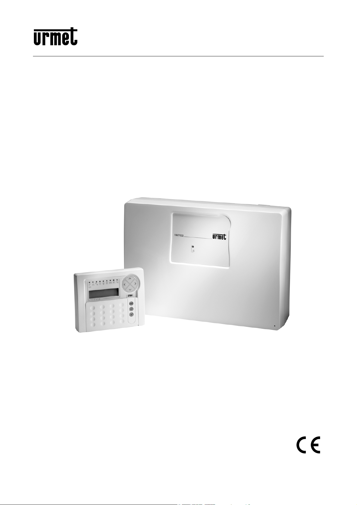
BUS CONTROL PANEL 8/32 INPUTS
Ref.1067/032
Ref.1067/042
PROGRAMMING MANUAL
Page 2

TABLE OF CONTENTS
1 PREFACE................................................................................................................................................. 6
1.1 NAVIGATION THROUGH MENUS ............................................................................................. 6
2 COMMAND DEVICES.............................................................................................................................. 8
2.1 1067/021 DISPLAY KEYPAD ...................................................................................................... 8
2.2 ELECTRONIC KEY READER 1067/334–1067/335 AND PROXIMITY READER 1067/434 –
1067/435................................................................................................................................................... 9
2.3 1058/035 REMOTE CONTROL................................................................................................... 9
2.4 SYSTEM STATUS INFORMATION........................................................................................... 10
2.4.1 System status display......................................................................................................................... 10
2.4.2 Open inputs display............................................................................................................................ 10
2.4.3 Excluded inputs display...................................................................................................................... 10
2.4.4 Examine alarm and tamper memory .................................................................................................. 10
2.4.5 Alarm and tamper memory deleting ................................................................................................... 10
2.4.6 Display failures and faults .................................................................................................................. 10
3 ALARMS, EVENTS AND SIGNALLING................................................................................................. 11
3.1 DESCRIPTION OF ALARMS, EVENTS.................................................................................... 11
3.1.1 Burglar Alarm ..................................................................................................................................... 11
3.1.2 Pre-alarm ........................................................................................................................................... 11
3.1.3 Tamper alarm..................................................................................................................................... 12
3.1.4 Wrong code alarm.............................................................................................................................. 12
3.1.5 Panic alarm ........................................................................................................................................ 13
3.1.6 Silent panic alarm............................................................................................................................... 13
3.1.7 Hold-up alarm..................................................................................................................................... 13
3.1.8 Emergency alarm ............................................................................................................................... 14
3.1.9 Fire alarm ........................................................................................................................................... 14
3.1.10 Fire reset event .................................................................................................................................. 15
3.1.11 Technological event ........................................................................................................................... 15
3.1.12 Door Opener Event ............................................................................................................................ 15
3.1.13 Courtesy Light Event.......................................................................................................................... 15
3.1.14 Failure alarm from a Failure input ...................................................................................................... 15
3.1.15 Telephone failure alarm...................................................................................................................... 16
3.1.16 LAN failure alarm ............................................................................................................................... 16
3.1.17 System failure alarm........................................................................................................................... 16
3.1.18 Lack of power event ........................................................................................................................... 17
3.1.19 Alarm generated by continuous lack of power.................................................................................... 17
3.1.20 Low battery alarm control panel and radio devices ............................................................................ 17
3.1.21 Maintenance event............................................................................................................................. 17
3.1.22 Input exclusion event.......................................................................................................................... 18
3.2 ACOUSTIC SIGNALLINGS ....................................................................................................... 18
3.2.1 Entry/exit time signalling..................................................................................................................... 18
3.2.2 Arm Warning ...................................................................................................................................... 18
3.2.3 Gong .................................................................................................................................................. 18
3.2.4 Output radio device status report (sirens) .......................................................................................... 18
4 SYSTEM START-UP.............................................................................................................................. 19
4.1 SYSTEM ACCESS CODES....................................................................................................... 19
4.1.1 Default codes ..................................................................................................................................... 19
4.1.2 Access to functions ............................................................................................................................ 19
4.2 ALPHANUMERIC CHARACTERS INPUT................................................................................. 21
4.3 LANGUAGE SELECTION.......................................................................................................... 21
4.4 TIME/DATE SETTING – SUMMER TIME ................................................................................. 21
4.5 ZONES PROGRAMMING.......................................................................................................... 22
4.5.1 Arming mode – Standard / Autoexclusion / Block arming................................................................... 22
4.5.2 Zones programming ........................................................................................................................... 22
4.6 WIRED INPUT PROGRAMMING .............................................................................................. 23
4.6.1 Inputs encoding.................................................................................................................................. 23
4.6.2 Inputs types........................................................................................................................................ 23
4.6.3 Inputs specialisations ......................................................................................................................... 24
DS1067-035A 2 LBT8633
Page 3

Bypass allowed .................................................................................................................................. 25
4.6.4
4.6.5 Ancillary functions (Gong, Courtesy light, Door opening, Absence of move) ..................................... 25
4.6.6 Burglar inputs attributes (Release type, AND / OR zones, AND inputs)............................................ 25
4.6.7 Input associated to a video camera.................................................................................................... 25
4.6.8 Input programming ............................................................................................................................. 26
4.7 WIRED OUTPUTS PROGRAMMING........................................................................................ 27
4.7.1 Outputs encoding ............................................................................................................................... 27
4.7.2 Outputs types ..................................................................................................................................... 27
4.7.3 Outputs specialisations ...................................................................................................................... 28
4.7.4 Output programming .......................................................................................................................... 30
4.8 KEYPADS PROGRAMMING..................................................................................................... 31
4.9 READERS PROGRAMMING..................................................................................................... 32
4.10 RADIO DEVICES PROGRAMMING.......................................................................................... 32
4.10.1 Radio inputs encoding........................................................................................................................ 33
4.10.2 Inputs type.......................................................................................................................................... 33
4.10.3 Radio input customizations ................................................................................................................ 33
4.10.4 Radio input attributes: Bypass allowed, Release type, Common input, AND inputs .......................... 34
4.10.5 Radio ancillary functions (Gong, Courtesy light, Door opener, Absence of move)............................. 34
4.10.6 Assigning a radio input to a videocamera........................................................................................... 34
4.10.7 Radio input programming................................................................................................................... 34
4.10.8 Radio output programming (SIRENS) ................................................................................................ 36
4.10.9 Radio output coding ........................................................................................................................... 36
4.10.10 Radio output customizations .............................................................................................................. 36
4.10.11 Status report....................................................................................................................................... 36
4.10.12 Radio output programming................................................................................................................. 37
4.11 1058/035 REMOTE CONTROL PROGRAMMING.................................................................... 37
4.12 ADVANCED PROGRAMMING.................................................................................................. 39
4.12.1 Remote management system code setting ........................................................................................ 39
4.13 SYSTEM GENERAL PARAMETERS - TIMING........................................................................ 39
4.14 COMMUNICATOR..................................................................................................................... 40
4.14.1 Telephone credit being used up signalling (for GSM only) ................................................................. 40
4.14.2 Telephone numbers ........................................................................................................................... 40
4.14.3 Telephone number storing ................................................................................................................. 41
4.14.4 Telephone number change ................................................................................................................ 42
4.14.5 Telephone number deleting................................................................................................................ 42
4.14.6 Vocal messages................................................................................................................................. 42
4.14.7 Vocal messages listening................................................................................................................... 44
4.14.8 Vocal messages recording ................................................................................................................. 44
4.14.9 SMS messages writing....................................................................................................................... 45
4.14.10 SMS messages deleting..................................................................................................................... 45
4.14.11 Alarm sending .................................................................................................................................... 46
4.14.12 Sequence of alarm message sending and block of calls.................................................................... 47
4.14.13 PSTN parameters............................................................................................................................... 47
4.14.14 GSM parameters................................................................................................................................ 48
4.14.15 PSTN line test .................................................................................................................................... 49
4.14.16 Periodic communication test .............................................................................................................. 50
4.14.17 Remote control backup ...................................................................................................................... 50
4.14.18 Answer machine................................................................................................................................. 51
4.14.19 Subscriber code for Alarm reception centre ....................................................................................... 51
4.14.20 Return call .......................................................................................................................................... 52
4.14.21 Call time delay.................................................................................................................................... 52
4.14.22 Phone lines enable............................................................................................................................. 53
4.14.23 IDP message structure...................................................................................................................... 54
4.15 INSTALLER ............................................................................................................................... 55
4.15.1 Installer enabling ................................................................................................................................ 55
4.15.2 Installer disabling ............................................................................................................................... 55
4.15.3 Change code...................................................................................................................................... 55
4.16 USERS....................................................................................................................................... 56
4.16.1 User enabling ..................................................................................................................................... 56
4.16.2 User disabling .................................................................................................................................... 56
4.16.3 How to associate a user to the system............................................................................................... 56
4.16.4 How to associate users to zones........................................................................................................ 57
4.16.5 Change code...................................................................................................................................... 57
4.16.6 User code reset.................................................................................................................................. 57
DS1067-035A 3 LBT8633
Page 4

User a clear-text name....................................................................................................................... 58
4.16.7
4.17 KEYS.......................................................................................................................................... 58
4.17.1 Key acquisition ................................................................................................................................... 58
4.17.2 Key deleting ....................................................................................................................................... 59
4.17.3 Key configuration ............................................................................................................................... 59
4.17.4 Key enabling ...................................................................................................................................... 60
4.17.5 Key disabling...................................................................................................................................... 60
4.18 TIMING PROGRAMMER........................................................................................................... 60
4.18.1 Functioning principles......................................................................................................................... 60
4.18.2 Programming procedure..................................................................................................................... 61
4.18.3 Command deleting ............................................................................................................................. 62
4.19 PROGRAMMING BY COMPUTER ........................................................................................... 62
4.19.1 Technical prerequirements for data transfer....................................................................................... 63
4.19.2 Personal computer requirements ....................................................................................................... 63
4.19.3 Saving data to USB key and restoring data........................................................................................ 63
4.20 SYSTEM TEST.......................................................................................................................... 64
4.20.1 Inputs test........................................................................................................................................... 64
4.20.2 Outputs test........................................................................................................................................ 64
4.20.3 Battery test......................................................................................................................................... 65
4.20.4 Vocal call test ..................................................................................................................................... 65
4.20.5 Alarm reception centre call test .......................................................................................................... 65
4.20.6 GSM field test..................................................................................................................................... 66
4.20.7 Radio devices test.............................................................................................................................. 66
4.20.8 Environmental listening test ............................................................................................................... 68
4.20.9 Final tests........................................................................................................................................... 68
4.21 EVENT LOG DELETING ........................................................................................................... 68
4.22 USERS TRAINING .................................................................................................................... 68
5 SYSTEM MANAGEMENT...................................................................................................................... 69
5.1 ARMING..................................................................................................................................... 69
5.1.1 Total arming with keypad ................................................................................................................... 69
5.1.2 Total arming with electronic or proximity key...................................................................................... 69
5.1.3 Total arm by remote control ............................................................................................................... 69
5.1.4 Partial arming with keypad ................................................................................................................. 70
5.1.5 Partial arming with electronic or proximity key ................................................................................... 70
5.1.6 Partial arm by remote control ............................................................................................................. 70
5.2 DISARMING............................................................................................................................... 71
5.2.1 Total disarming with keypad............................................................................................................... 71
5.2.2 Total disarming with electronic or proximity key ................................................................................. 71
5.2.3 Total disarming by remote control ...................................................................................................... 71
5.2.4 Partial disarming with keypad............................................................................................................. 71
5.2.5 Hold-up disarming from keypad ......................................................................................................... 71
5.2.6 Stop of the active alarms.................................................................................................................... 72
5.2.7 Wrong code entering.......................................................................................................................... 72
5.2.8 Masking on keypads and readers ...................................................................................................... 72
5.3 FUNCTION KEYS WITH DIRECT ACCESS ............................................................................. 72
5.3.1 1058/035 remote control direct access function key “+”..................................................................... 72
5.4 DATE AND TIME CHANGING................................................................................................... 73
5.5 EVENT LOG .............................................................................................................................. 73
5.5.1 Read the Event log............................................................................................................................. 73
5.5.2 Meaning of event data........................................................................................................................ 73
5.5.3 Event log deleting............................................................................................................................... 73
5.6 USER REMOTE MANAGEMENT.............................................................................................. 74
5.6.1 Answering machine skip..................................................................................................................... 74
5.6.2 Remote management with SMS messages ....................................................................................... 74
5.6.3 Request to send emails from Videoserver by SMS message............................................................. 74
5.6.4 Commandable outputs activation with no cost ................................................................................... 75
5.6.5 Remote management with vocal menu .............................................................................................. 75
5.6.6 Table with list of DTMF commands for vocal answer machine........................................................... 76
5.6.7 Environmental listening ...................................................................................................................... 76
5.7 TIMING PROGRAMMER........................................................................................................... 76
5.7.1 Deferred automatic system arm ......................................................................................................... 76
DS1067-035A 4 LBT8633
Page 5

Timing programmer enabling ............................................................................................................. 77
5.7.2
5.7.3 Timing programmer disabling............................................................................................................. 77
5.8 INPUTS EXCLUSION AND INCLUSION................................................................................... 77
5.8.1 Input exclusion ................................................................................................................................... 77
5.8.2 Input inclusion .................................................................................................................................... 78
5.9 PERIODIC TESTS ..................................................................................................................... 78
5.10 VARIOUS................................................................................................................................... 78
5.10.1 Display Info ........................................................................................................................................ 78
5.10.2 Buzzer volume adjustment................................................................................................................. 79
5.10.3 Display contrast adjustment ............................................................................................................... 79
5.10.4 Back-lighting adjustment of keypad and display................................................................................. 79
5.11 MAINTENANCE......................................................................................................................... 79
5.11.1 Language change .............................................................................................................................. 79
5.11.2 Device address display ...................................................................................................................... 80
5.11.3 Software release display .................................................................................................................... 80
5.11.4 Partial reset ........................................................................................................................................ 80
5.11.5 Global reset........................................................................................................................................ 81
5.11.6 Backup-Restore ................................................................................................................................. 81
6 MENU ..................................................................................................................................................... 82
6.1 MASTER MENU ........................................................................................................................ 82
6.1.1 Event log submenu............................................................................................................................. 82
6.1.2 Settings submenu............................................................................................................................... 83
6.1.3 Enabling submenu.............................................................................................................................. 83
6.1.4 Test submenu .................................................................................................................................... 84
6.1.5 Telephone dialer submenu................................................................................................................. 84
6.2 INSTALLER MENU.................................................................................................................... 85
6.2.1 Event log submenu............................................................................................................................. 85
6.2.2 Settings submenu............................................................................................................................... 86
6.2.3 Test submenu .................................................................................................................................... 86
6.2.4 System programming submenu ......................................................................................................... 87
6.2.5 Parameters submenu......................................................................................................................... 90
6.2.6 Telephone dialer submenu................................................................................................................. 90
6.2.7 Maintenance submenu ....................................................................................................................... 91
6.3 USER MENU ............................................................................................................................. 91
6.3.1 Settings Submenu.............................................................................................................................. 91
7 PROGRAMMING SUMMARY TABLES AND FACTORY SETTING ..................................................... 92
7.1 INSTALLER MENU.................................................................................................................... 92
7.2 ZONES....................................................................................................................................... 92
7.3 USERS....................................................................................................................................... 92
7.4 KEYS.......................................................................................................................................... 93
7.5 GENERAL PARAMETERS........................................................................................................ 93
7.6 CONTROL PANEL INPUTS ...................................................................................................... 94
7.7 CONTROL PANEL OUTPUTS .................................................................................................. 95
7.8 EXPANSION INPUTS................................................................................................................96
7.9 EXPANSION OUTPUTS............................................................................................................ 97
7.10 KEYPADS INPUTS.................................................................................................................... 98
7.11 radio expansion INPUTS ........................................................................................................... 99
7.12 radio expansion OUTPUTS (sirenS)........................................................................................ 100
7.13 READERS INPUTS ................................................................................................................. 101
7.14 KEYPADS –ZONES ASSOCIATION....................................................................................... 103
7.15 READERS-ZONES ASSOCIATION ........................................................................................ 103
7.16 REMOTE CONTROL-ZONES KEYS ASSOCIATION............................................................. 104
7.17 COMMUNICATOR................................................................................................................... 105
7.18 TIMING PROGRAMMER......................................................................................................... 107
DS1067-035A 5 LBT8633
Page 6
1 PREFACE
STRUCTURE OF THIS MANUAL
The manual is divided into chapters and discussed subjects are arranged sequentially to accompany each step of
system programming and configuration.
Descriptions to design, install and maintain the system are given in Installation Manual, where devices acquiring
procedure is indicated.
Descriptions for system use from end user are given in User Manual.
Standards used in this manual
For the sake of clarity, the following conventional standards are used throughout this manual:
For example 120 OK means “enter 120 and then press the OK key”.
▲, ►, ▼ and ◄ indicate the corresponding navigation arrow keys on the keypad.
Finally, take care of the following symbols:
This symbol indicates an important warning.
This symbol indicates an suggestion.
1.1 NAVIGATION THROUGH MENUS
1067 system provides for 4 menus:
- Technical menu which can be accessed by entering
This menu is dedicated to system installer and described at paragraph 3.15.
The whole tree of Installer Menu is illustrated at paragraph 5.2.
- Master menu which can be accessed by entering Master Code (default 111111) OK MENU
This menu is dedicated to system main user and described in User Manual.
The whole tree of Master Menu is illustrated at paragraph 5.1.
- User menu which can be accessed by entering a
This menu is dedicated to system users and described in User Manual.
The whole tree of User Menu is illustrated at paragraph 5.3.
- Free access menu which can be accessed by directly entering MENU
from this menu, some information on system status can be achieved.
The menus are organised in a tree-like structure, that is with more or less deep submenus including more items.
Typically, on display 1
menu.
As an example:
To scroll through menu items, use vertical scrolling keys ▲ and ▼.
To access a submenu, press OK.
To confirm a choice within a menu, press OK otherwise press ESC.
To go back by one level, press ESC.
To quit a menu, press ESC more times.
If no key is pressed, after one minute the system automatically exits the menu.
Pressing any key is signalled by a short beep sound.
E.g. valid code confirmation is signalled by beep-beep!.
Entering a parameter which is wrong, e.g. owing to a not valid code, is signalled by a low tone.
st
line, the item appears of menu being used and, on display 2nd line, the submenu items of the
Technical Code (default 000000) OK MENU
User Code (es. default 000020) OK MENU
EVENT LOG
SYSTEM
DS1067-035A 6 LBT8633
Page 7

The display of the status of zones and their association to a number of functions during programming is of graphic type.
Example:
On display 2
The meaning during programming is:
nd
line, graphic symbols appear matching digits 1 ÷ 6 present on the mask;
□ = zone not associated to function
■ = zone associated to function
ZN01:...
□□0□■...
. = zone not existing
The meaning during use is:
□ = zone not active
0 = zone not active with one or more inputs open
■ = zone active
. = zone not existing
On display 1
By keys ◄ and ► you can move the cursor to select desired zone.
Where provided for, you can either associate or not associate the zone where the cursor is to be located by pressing
keys ▲ and ▼. At termination, press key OK to confirm your choice.
Further information is reported in paragraph describing single functions.
st
line, the zone is indicated on which cursor and cursor name are positioned.
DS1067-035A 7 LBT8633
Page 8
2 COMMAND DEVICES
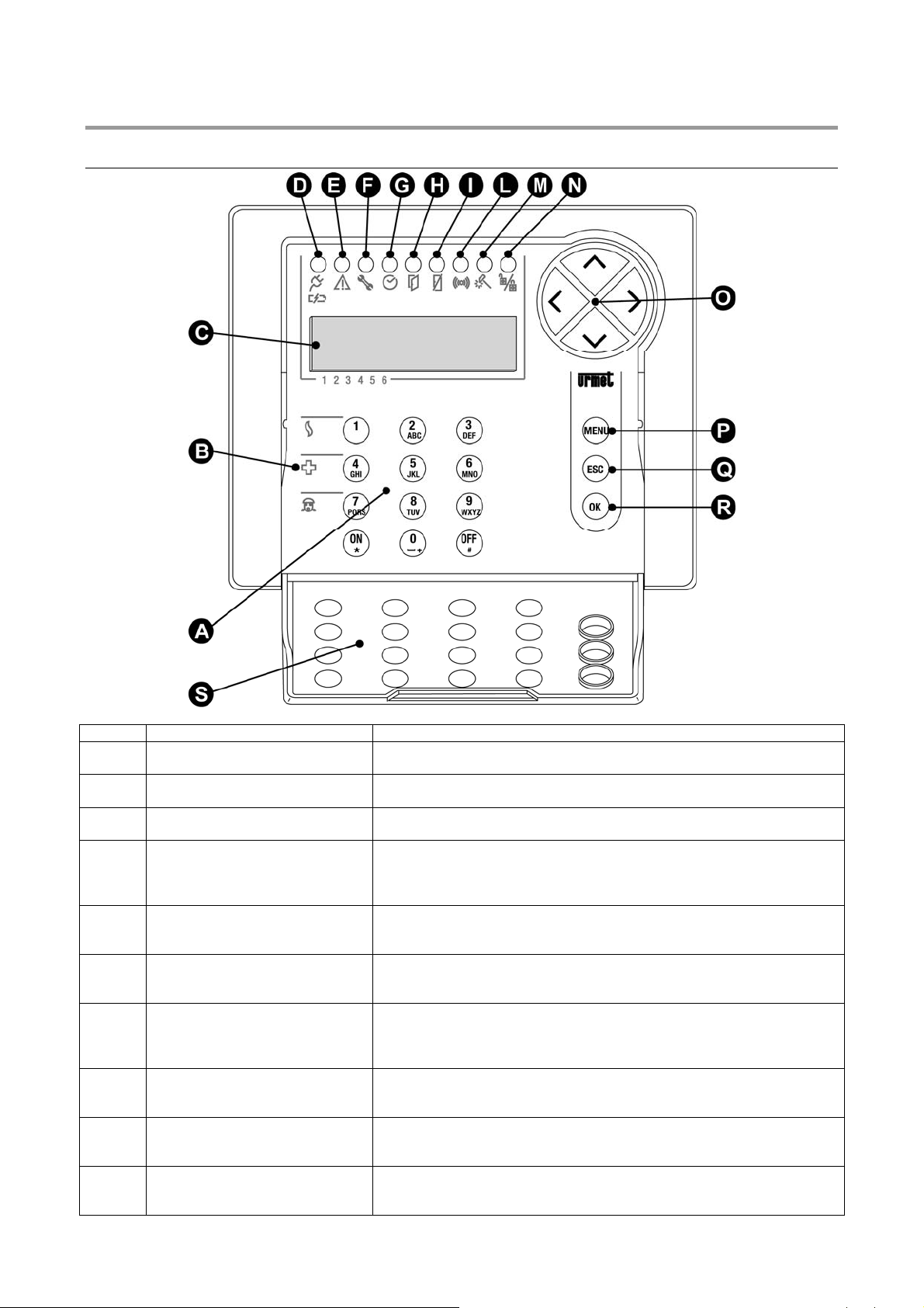
2.1 1067/021 DISPLAY KEYPAD
Ref. Description Use or provided indications
A Keypad Used to enter the access code, to select some functions and to program
the control panel
B Function keys Used to activate additional system functions.
See § 5.3
C LCD 2x16 characters display Shows date and time when in stand-by mode, detailed information on
system status, the event log and the programming menus.
D Green LED
Control panel mains voltage and
battery charge
E Yellow LED
failures
F Red LED
maintenance
G Green LED
Timing programmer status (P.O.)
H Red LED
Open inputs
I Red LED
Excluded inputs
L Red LED
alarm memory
On = mains power supply 230 V~ available and battery charged
Off = mains power supply 230 V~ not available and battery charged
Blinking = low battery
See Installation Manual.
Off = normal operation
On = Failure present
See § 2.4.6
Off = normal operation
On = system in maintenance
See § 5.11
Off = Timing Programmer disabled
On = Timing Programmer enabled
Blinking = automatic arm warning
See § 4.18
Off = inputs in stand-by mode
On = open inputs
See § 2.4.2
Off = all inputs included
On = excluded inputs
See § 2.4.3
Off = no alarms
On = alarm memory
See § 2.4.4
DS1067-035A 8 LBT8633
Page 9
M Red LED
tamper memory
Off = no tamper
On = tamper memory
See § 2.4.4
N Green LED
System status
On = system totally armed
Off = system totally disarmed
Blinking = system partially armed
See § 2.4.1
O Arrow keys Scroll the menu items; change the value of some parameters.
P
Q
R
MENU key
ESC key
OK key
Access to the menu.
Back to the upper level menu
Confirms the access code or any other entered data; confirms the selected
menu item and goes to its submenu.
S Cover It protects numerical keys.
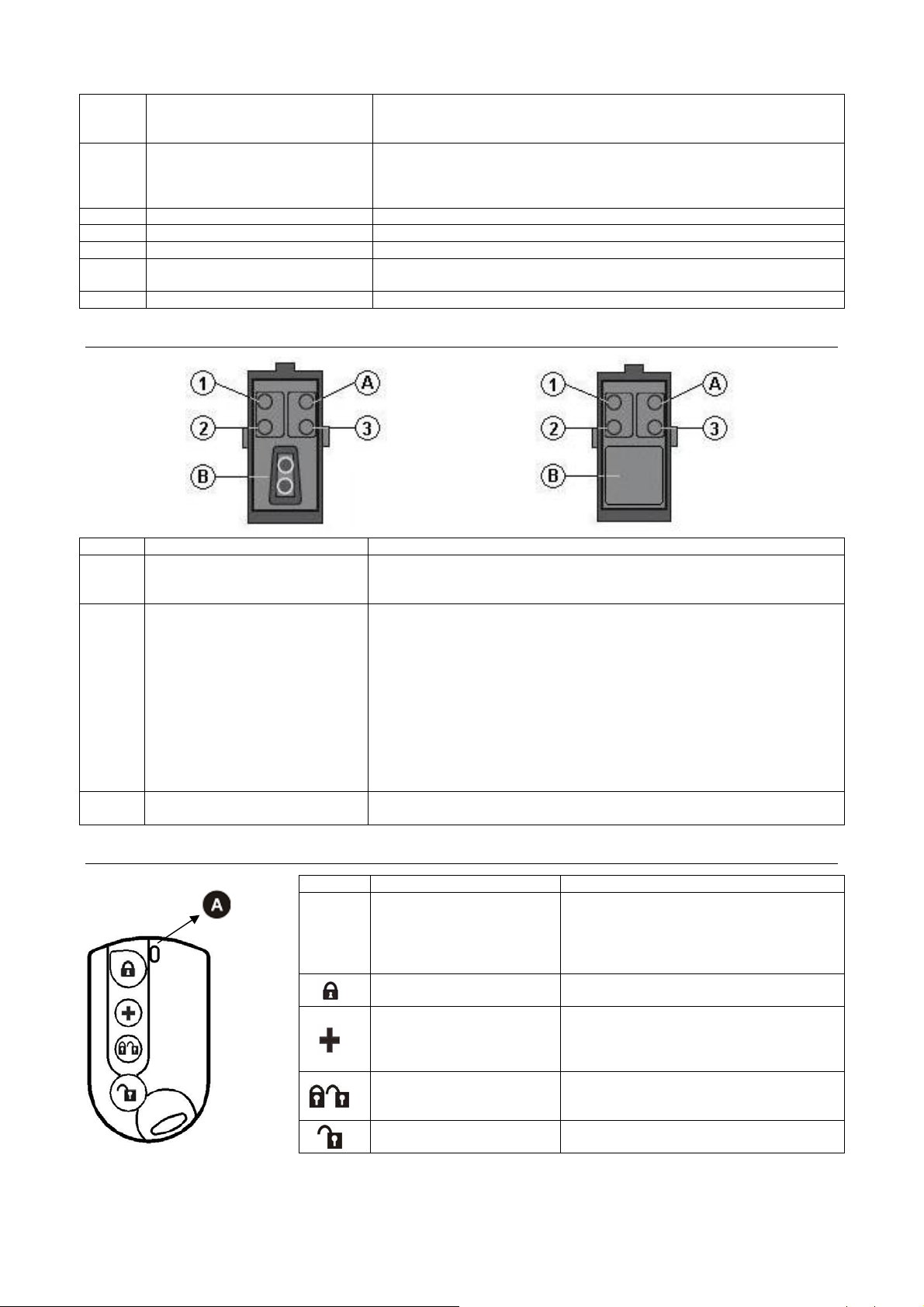
2.2 ELECTRONIC KEY READER 1067/334–1067/335 AND PROXIMITY READER 1067/434 – 1067/435
Description Use or provided indications
1
2 3
A
B
(Green) LED for status of
associated zones
Yellow LED
summarising alarms and
signalling
Keyhole or
Transponder
Off = all zones associated to the LED are not active
On = all zones associated to the LED are active
Blinking = at least one zone associated to the LED is active
Off = no signalling for zones associated to electronic key reader
On= alarm signalling stored for zones associated to electronic key reader
or tampering signalling or system failure signalling (the LED goes off at
next system arm, if the alarm has gone off in the meantime or until the
failure is repaired).
Blinking = at least one open input is present among zones associated
electronic key reader.
If alarms or failures and open inputs are present at the same time, the
LED is on steady.
In general putting on this LED is for suggesting to control signalling details
on system keypad.
1067/334 – 1067/35 hole to insert electronic key.
1067/434 – 1067/435 detector for transponder key.
2.3 1058/035 REMOTE CONTROL
NOTE: device utilizable with 1067 control panel and 1067/021 keypad software version 3.00 or higher and with an
1067/010 radio expansion.
Ref. Description Use or provided indications
ON Red= this LED goes on blinking when
pressing any key, followed by a beep if the
control unit has received the command.
ON Green= pressing any key, this LED
A
Bi-colour LED
Red / Green
indicates the low battery status.
Arm
Key 2
Programmable
Key 1
depending on the
control unit
Key 3
Arm/disarm
Toggle
Key 4
Disarm
This key arms the zones associated.
This key is set univocally either to OUTPUT
device arm/disarm function or to generate 4
different alarm types: Silent Panic, Audible
panic, Emergency, Fire alarm.
This key Arms/ Disarms with toggle function
the zones associated
This key disarms the zones associated
DS1067-035A 9 LBT8633
Page 10
2.4 SYSTEM STATUS INFORMATION
2.4.1 System status display
System status is shown by summarising LED present on keypads and electronic key readers.
Every user, included Master and Installer, can display in detail the system status for the parts of his competence (will be
displayed only the zones where they can operate).
To display system status, enter your code and press OK key, then MENU, select item «SYSTEM STATUS» and confirm
by pressing OK key
On display 2
Their meaning is the following:
nd
line, graphic symbols appear matching digits 1 ÷ 6 present on the mask;
□ = zone not active
ZN01:...
□□□□■...
0 = zone not active with one or more inputs open
■ = zone active
. = zone not existing
By keys ◄ and ► you can move through zones; zones name will appear on upper line.
NOTE: if this option is desired, it is possible to display the zones state instead of Date-Time; for details see paragraph
5.10.1 Display Info.
2.4.2 Open inputs display
The red LED (H) on keypad and LED (A) on key readers signals the presence of one or more inputs resulting to be
open.
NOTE: these LEDs also signal the opening of excluded inputs.
To display input addresses in detail, directly press MENU, then, by keys, ► and ◄, select «OPEN INPUTS» and confirm
with OK.
Scroll through the list by keys ▲ and ▼; inputs are identified as “logical address: physical address”.
2.4.3 Excluded inputs display
The red LED (I) on keypad signals the presence of one or more inputs resulting to be excluded.
An input can only be excluded if it was programmed with bypass allowed – see § 4.6.8.
An input can be excluded manually – see § 5.8.1, or automatically by system at activation – see § 4.5.1, or owing to its
alarm count overflow – see § 4.13.
To display excluded inputs in detail, directly press MENU, then by keys ► and ◄ select «EXCLUDED INPUTS», press
OK key, enter a valid code and confirm by OK. On the display unit, «READ LIST» appears, confirm by OK and scroll
through excluded inputs list by keys ▲ and ▼.
2.4.4 Examine alarm and tamper memory
In case of tamper or alarm, events are signalled by appropriate LEDs (on keypad and key readers) and stored in the
control panel. Afterwards it is possible to see in the keypad display the details of events causes.
To display details follow the instructions below:
1. Press on the keypad MENU key.
2. Press ► key until “TAMPERS MEM” or “ALARMS MEM” appears. Press OK key on the
selected item.
3. Scroll with ▲ and ▼ keys the list of tamper or alarm causes.
4. To exit from the menu press ESC key repeatedly.
2.4.5 Alarm and tamper memory deleting
When the event cause is removed, the alarm/tamper memory is deleted (LED off) at the next arm of all the zones
associated to concerned inputs.
2.4.6 Display failures and faults
The presence of a failure or fault, such as a breakdown in telephone line, of an input or a radio device, is signalled by
special yellow LED (E) on keypad and LED (A) on key readers.
To display details of faults detected, directly press MENU, then, by keys, ► and ◄, select «FAILURES».
SYSTEM STATUS
ALARMS MEM
ALARMS MEM
In02:...
DS1067-035A 10 LBT8633
Page 11
3 ALARMS, EVENTS AND SIGNALLING
3.1 DESCRIPTION OF ALARMS, EVENTS
The 1067 system manages different types of alarms, described below with their characteristics.
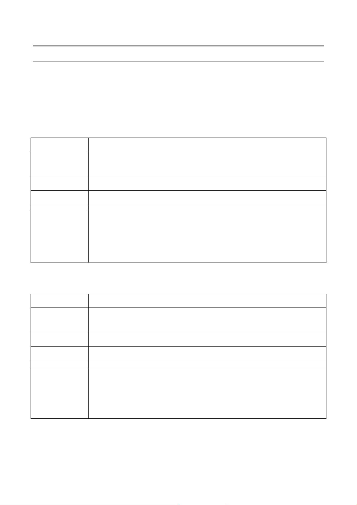
3.1.1 Burglar Alarm
It is the alarm of anti-burglar system. System 1067 manages one burglar alarm for each zone; to each single zone there
can be paired its own output actuators, such as sirens.
Various possibilities are provided for to determine when burglar inputs have to generate an Alarm: burglar inputs can be
either single or clustered (e.g. combined in AND mode, owing to double release - see § 4.6).
NOTE: by activating function “Alarm count”, maximum number of alarms can be de termined caus ed by a detector in on e
day and as long as competence zone is activated.
generated if...
activates...
is stored...
is displayed...
is held...
is stopped by...
3.1.2 Pre-alarm
In anti-burglar system, a Pre-alarm can be used, as an example, to ring a buzzer all the times when detectors relating to
an outer area, such as a yard, detect the presence of a person.
generated if...
activates...
is stored...
is displayed...
is held...
is stopped by...
• an Burglar input is opened and at least one associated zone in OR mode is active
• an Burglar input is opened and all associated zones in AND mode are active
• the outputs programmed as Burglar/Tamper that have at least one zone shared with the input
that generated the event
• the communicator for voice, SMS, numerical or modem sending of the respective Burglar
alarm message (if programmed)
• in the event log
• in alarm volatile memory
• on the keypads which have at least one zone shared with the input
• on the readers which have at least one zone shared with the input
• for Burglar/Tamper/Panic Alarm Time
• entering a valid code on a keypad which has at least one zone shared with the input that
generated the event
• insertion of a valid key
• a zones disarm command given by a key input that has at least one zone shared with the
input that generated the event
• a DTMF disarm command entered with a phone call to the control panel
• disarm command from remote control having at least one shared zone with the input which
has generated the event.
• a alarm input is opened and at least one associated zone in OR mode is active
• a alarm input is opened and all associated zones in AND mode are active
• the outputs programmed as Pre-alarm that have at least one zone shared with the input that
generated the event
• the communicator for numerical or modem sending of the respective Pre-alarm message (if
programmed)
• in the event log
• in alarm volatile memory
• on the keypads which have at least one zone shared with the input
• on the readers which have at least one zone shared with the input
• for Burglar/Tamper/Panic Alarm Time
• entering a valid code on a keypad which has at least one zone shared with the input that
generated the event
• insertion of a valid key
• a zones disarm command given by a key input that has at least one zone shared with the
input that generated the event
• a DTMF disarm command entered with a phone call to the control panel
• disarm command from remote control having at least one shared zone with the input which
has generated the event.
DS1067-035A 11 LBT8633
Page 12
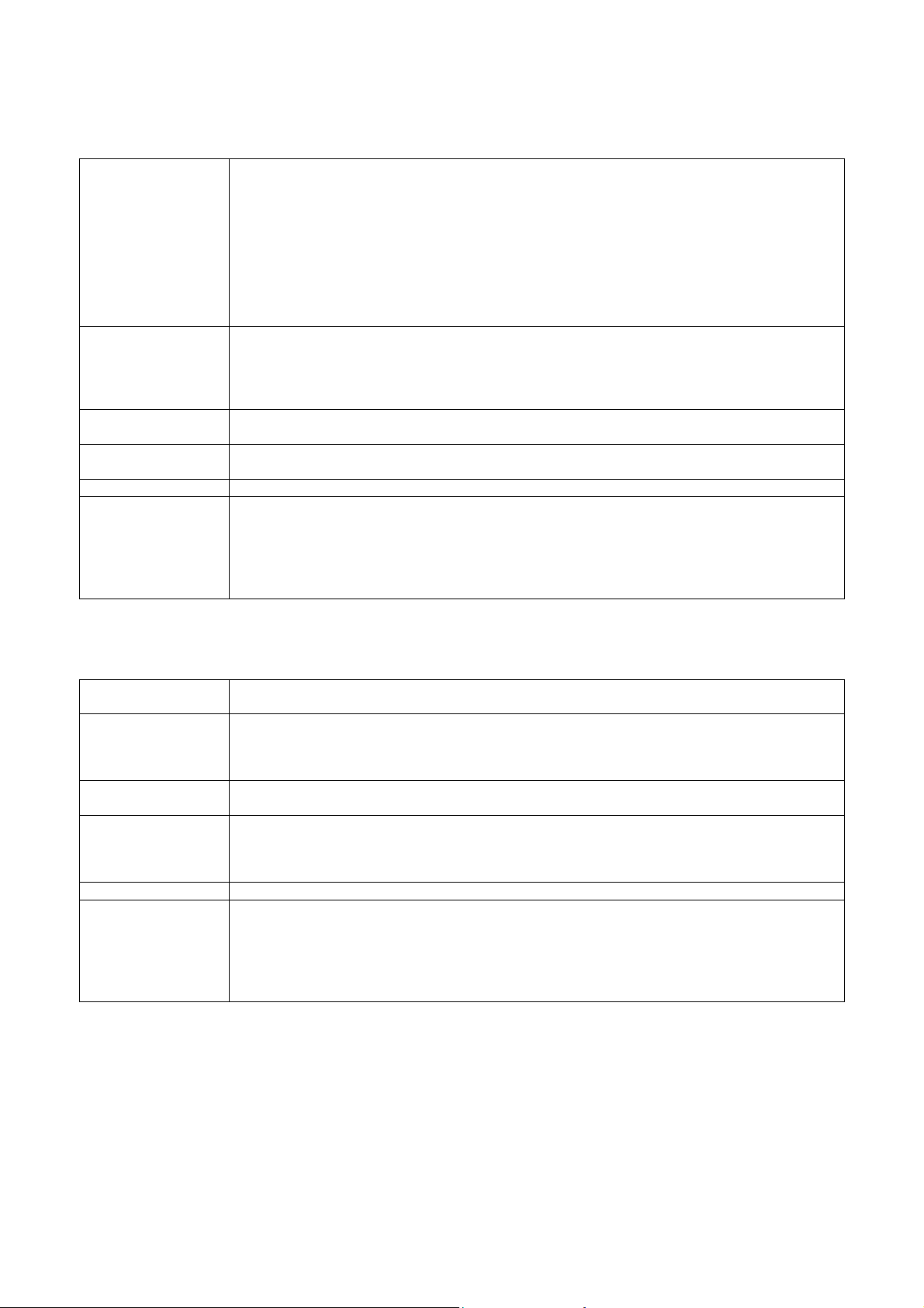
3.1.3 Tamper alarm
It is the alarm which is generated if somebody tries to tamper the system. It is always (24H) active and is temporarily
disabled by putting the system to maintenance status.
generated if...
activates...
Is stored...
Is displayed...
is held...
is stopped by...
3.1.4 Wrong code alarm
It is the alarm which is generated if somebody tries to identify a valid code to deactivate the system. It is always (24H)
active and is temporarily disabled by putting the system to maintenance status.
generated if...
activates...
is stored...
is displayed...
is held...
is stopped by...
• a Tamper is opened (control panel, keypads, or radio devices like 1058/ 101; 201; 405; 035)
• the SAB line of the control panel or expansions is opened or unbalanced
• a double balancing input is unbalanced (short circuit or wires cut)
• an input programmed as Tamper is opened
• a device connected on the bus does not answer for many consecutive times
• a radio device will not answer to the relevant radio expansion for a time higher than the pre-
selected configuration (Supervision)
• a radio device extrinsic to the system is loading or jamming the radio band of the 1067/010
expansion (Jamming)
The alarm is generated regardless of the zones status (24h).
• the outputs programmed as Tamper and Burglar/Tamper that have at least one shared zone
(for double balancing inputs). In the other cases it activates the Tamper outputs regardless of
the zones.
• the communicator for voice, SMS, modem or numerical sending of the respective Tamper
alarm message (if programmed)
• In the event log
• in volatile tamper memory
• on keypads
• on readers
• for Burglar/Tamper/Panic Alarm Time
• entering of a valid code in the keypad
• insertion of a valid key
• a zones disarm command given by a key input
• a DTMF disarm command entered with a phone call to the control panel
• disarm command from remote control having at least one shared zone with the input which
has generated the event.
• a wrong code is entered four consecutive times (the count is reset by entering a valid code)
The alarm is generated regardless of the zones status (24h).
• the outputs programmed as Tamper and Burglar/Tamper that have at least one zone shared
with the keypad where the wrong code has been entered.
• the communicator for modem or numerical sending of the respective and detailed wrong
code alarm description (if programmed)
• in the event log
• in tamper volatile memory
• on the keypads which have at least one zone shared with the keypad where the wrong code
has been entered.
• on the readers which have at least one zone shared with the keypad where the wrong code
has been entered.
• for burglar/tamper/panic alarm time
• entering of a valid code in the keypad
• insertion of a valid key
• a zones disarm command given by a key input
• a DTMF disarm command entered with a phone call to the control panel
• disarm command from remote control having at least one shared zone with the input which
has generated the event.
DS1067-035A 12 LBT8633
Page 13
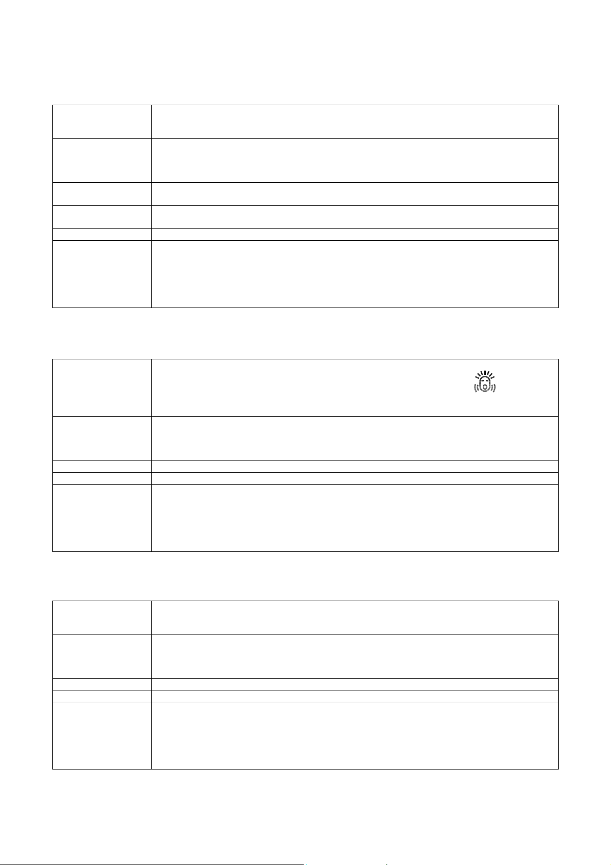
3.1.5 Panic alarm
It is an alarm which can be triggered by a user in a situation of danger. It is always (24H) active and is temporarily
disabled by putting the system to maintenance status.
generated if...
• a Panic input is opened
• the remote control function key “ + “ (if programmed) is pressed for 5 seconds at least
The alarm is generated regardless of the zones status (24h).
activates...
• the outputs programmed as Panic that have at least one zone shared with the input that
generated the event
• the communicator for voice, modem or numerical sending of the respective Panic alarm
message (if programmed)
is stored...
• in the event log
• in alarm volatile memory
is displayed...
• on the keypads which have at least one zone shared with the input
• on the readers which have at least one zone shared with the input
is held...
is stopped by...
• for burglar/tamper/panic alarm time
• entering of a valid code in the keypad
• insertion of a valid key
• a zones disarm command given by a key input
• a DTMF disarm command entered with a phone call to the control panel
• disarm command from remote control having at least one shared zone with the input which
has generated the event.
3.1.6 Silent panic alarm
It is an alarm which can be triggered by a user in situations of danger and must not draw wrongdoer’s attention. It is
always (24H) active and is temporarily disabled by putting the system to maintenance status.
generated if...
• a Silent panic input is opened
• function key Silent panic on keypad is kept pressed for at least 3 seconds
• the remote control function key “+“ (if programmed) is pressed for 5 seconds at least
The alarm is generated regardless of the zones status (24h).
activates...
• the outputs programmed as Silent panic that have at least one zone shared with the input
that generated the event or with the keypad where the dedicated key has been pressed
• the communicator for voice, modem or numerical sending of the respective silent panic alarm
message (if programmed)
is stored...
is held...
is stopped by...
• in the event log
• for burglar/tamper/panic alarm time
• entering of a valid code in the keypad
• insertion of a valid key
• a zones disarm command given by a key input
• a DTMF disarm command entered with a phone call to the control panel
• disarm command from remote control having at least one shared zone with the input which
has generated the event.
3.1.7 Hold-up alarm
It is an alarm which can be triggered by a user when he/she is forced by a wrongdoer to deactivate the system. It is
always (24H) active and is temporarily disabled by putting the system to maintenance status.
generated if...
• an hold-up input is opened
• an hold-up code is entered with the keypad (code + 1)
The alarm is generated regardless of the zones status (24h).
activates...
• the outputs programmed as Hold-up that have at least one zone shared with the input or the
keypad.
• the communicator for voice, modem or numerical sending of the respective Hold-up alarm
message (if programmed)
is stored...
is held...
is stopped by...
• in the event log
• for a fixed time of 30 seconds
• entering of a valid code in the keypad
• insertion of a valid key
• a zones disarm command given by a key input
• a DTMF disarm command entered with a phone call to the control panel
• disarm command from remote control having at least one shared zone with the input which
has generated the event.
DS1067-035A 13 LBT8633
Page 14
3.1.8 Emergency alarm
System 1067 provides the capability to generate service signalling for an “emergency request” owing to either actuating a
dedicated key or detecting lack of movement in the environments.
NOTE: An “emergency request” is only to be considered as an anti-burglar system ancillary function; therefore, system
1067 cannot be used as a remote emergency system according to regulations in force.
generated if...
• an emergency input is opened
• a absence of movement input is not opened (every 12 hours)
• the keypad key associated to the emergency function is pressed for more than 3 seconds
• the remote control function key “ + “ (if programmed) is pressed for 5 seconds at least
The alarm is generated regardless of the zones status (24h).
activates...
• the outputs programmed as Emergency that have at least one zone shared with the input
that generated the event or with the keypad where the dedicated key has been pressed
• the communicator for voice, SMS modem or numerical sending of the respective Emergency
alarm message (if programmed) with vocal sending; listening is automatically activated at
end of message (see § 4.8)
is stored...
• in the event log
• in alarm volatile memory
Is displayed...
• on the keypads which have at least one zone shared with the input or the keypad that
generated the event
• on the readers which have at least one zone shared with the input or the keypad that
generated the event
is held...
is stopped by...
• for Emergency alarm time
• entering of a valid code in the keypad
• insertion of a valid key
• a zones disarm command given by a key input
• a DTMF disarm command entered with a phone call to the control panel after closing
environmental listening session, at end of emergency request vocal message repetition
• disarm command from remote control having at least one shared zone with the input which
has generated the event.
3.1.9 Fire alarm
System 1067 provides the capability to manage fire detectors (smoke, buttons,…) connecting them to properly
programmed inputs, to generate service signalling of “fire alarm” type.
Warning: “Fire alarm” is only to be considered as an anti-burglar system ancillary function; therefore,
system 1067 cannot be used as a fire detection system according to regulations in force.
To implement a system which fully meets the requirements of a fire detection system, please see Urmet general
catalogue.
generated if...
• a fire input is opened
• the keypad key associated to the fire function is pressed for more than 3 seconds
• the remote control function key “ + “ (if programmed) is pressed for 5 seconds at least
The alarm is generated regardless of the zones status (24h).
activates...
• the outputs programmed as Fire that have at least one zone shared with the input that
generated the event or with the keypad where the dedicated key has been pressed
• the communicator for voice, SMS modem or numerical sending of the respective Fire alarm
message (if programmed)
is stored...
• in the event log
• in alarm volatile memory
is displayed...
• on the keypads which have at least one zone shared with the input or the keypad that
generated the event
• on the readers which have at least one zone shared with the input or the keypad that
generated the event
is held...
• until is opened a Fire reset input that has at least one zone shared with the alarmed fire input
or with the keypad that generated the event
DS1067-035A 14 LBT8633
Page 15
3.1.10 Fire reset event
generated if...
activates...
• a fire reset input is opened
• for 1 second the outputs programmed as fire reset that have at least one zone shared with
the input that generated the event
is stored...
besides...
• in the event log
• stops the respective fire alarm
• resets the fire alarm volatile memory
• turns off the LED on the keypads and readers that signalled the event
Warning: in case of “fire alarm” signalling and subsequent alarm manual resetting, environmental conditions
have to be restored in premises where the alarm was generated and the detector has to be checked to have been
armed again in order to be able to detect a new alarm situation.
3.1.11 Technological event
System 1067 provides the capability to manage some domotics (heating activation, garden irrigation management, etc.)
functions through “technological events”, “door opener event” and “courtesy light event”.
“Technological events” and “courtesy light event” are always active (24H), while “door opener event” is only active when
zones are not active.
generated if...
activates...
• a technological input is opened
• the outputs programmed as Technological that have at least one zone shared with the input
that generated the event
• the communicator for voice, SMS modem or numerical sending of the respective
technological Service message (if programmed)
is stored...
is held...
• in the event log
• until is open at least one of the inputs programmed as Technological with at least one zone
shared with the input
3.1.12 Door Opener Event
generated if...
• a Burglar input is opened belonging to one or more zones to which Door Opener additional
function was enabled. All zones associated to the input must be not active.
• a key programmed as “access control” is inserted associated to one or more zones. All zones
associated to the key must be not active.
activates...
is stored...
is held...
• Door Opener programmed outputs associated to at least one input zone or key zone.
• into Event Log in case of actuation caused by a key
• about 2 seconds
3.1.13 Courtesy Light Event
generated if...
• a Burglar input is opened belonging to one or more zones to which Courtesy Light additional
function was enabled.
activates...
is held...
• Courtesy Light programmed outputs associated to at least one input zone.
• about 3 minutes
3.1.14 Failure alarm from a Failure input
System 1067 can be paired to the control of devices provided with a “failure” output.
generated if...
• an input programmed as Failure is opened
The alarm is generated regardless of the zones status (24h).
activates...
• the outputs programmed as Failure that have at least one zone shared with the input that
generated the event
• the communicator for voice, modem or numerical sending of the respective Failure message
(if programmed)
is stored...
• in the event log
• into failure and fault list
is displayed...
• with the failure yellow LED on the keypads
• with the yellow LED on the readers
is stopped by...
after the solution of
the problem the
control panel...
• when the input programmed as Failure is closed
• it activates the communicator for numerical sending of the respective message of failure
alarm end (if programmed)
• turns off the failure LED on keypads and readers
• stores in the event log the failure end
• deactivates the outputs programmed as failure
DS1067-035A 15 LBT8633
Page 16
3.1.15 Telephone failure alarm
generated... on PSTN line:
• after 3 automatic and consecutive failed PSTN tests
• if, with tones control enabled, after an event to be sent, when the line is seized the dial tone
is not detected for 3 consecutive times.
on GSM channel:
• in case of permanent absence of field
• if the PIN code is wrong
• without SIM or without credit used up
The alarm is generated regardless of the zones status (24h).
activates...
• the outputs programmed as Telephone failure
• the communicator for voice, modem or numerical sending of the respective Telephone failure
alarm message (if programmed)
is stored...
• in the event log
• into failure and fault list
is displayed...
• with the failure yellow LED on the keypads
• with the yellow LED on the readers
is stopped by... on PSTN line:
• when the telephone failure has been repaired, that is with a successful call on PSTN line, or
with a successful automatic PSTN test.
on GSM channel:
• a successful phone call, carried out on GSM channel, or at the field strength return
after the solution of
the problem the
control panel...
• activates the communicator for voice, modem or numerical sending of the respective
message of telephone failure alarm end (if programmed)
• turns off the failure LED on keypads and readers
• stores in the event log the telephone failure end
• deactivates the outputs programmed as telephone failure
3.1.16 LAN failure alarm
generated...
• after 3 consecutive failed tries to send the event on LAN Ethernet channel
The alarm is generated independently of zones status (24h)
activates...
• the communicator for voice, modem or numerical sending of relating LAN Failure Alarm (in
vocal mode, “system failure” message is sent).
is stored...
• into Event log
• into failure and fault list
is displayed...
• by failure yellow LED on keypads
• by yellow LED on readers
is stopped by...
after solving the
problem, control
panel...
3.1.17 System failure alarm
generated if...
• LAN failure restore, that is with a successful communication on LAN Ethernet channel
• activates communicator for numerical sending of relating end of LAN Failure Alarm message
(if programmed)
• puts off failure LED on keypads and readers
• stores end of LAN Failure into Event Log
• a fault occurs on system supply voltages
• a fault occurs on devices dialogue
• a Data flash fault occurs
The alarm is generated regardless of the zones status (24h).
activates...
• the outputs programmed as System failure
• the communicator for voice, modem or numerical sending of the respective system failure
alarm message (if programmed)
is stored...
• in the event log
• into failure and fault list
is displayed...
• with the failure yellow LED on the keypads
• with the yellow LED on the readers
is stopped by...
after the solution of
the problem the
control panel...
• the solution of the problem
• activates the communicator for voice, modem or numerical sending of the respective
message of failure alarm end (if programmed)
• turns off the failure LED on keypads and readers
• stores in the event log the failure end
• deactivates the outputs programmed as System failure
DS1067-035A 16 LBT8633
Page 17

3.1.18 Lack of power event
Generated if...
• the mains voltage is off for a shorter time than the programmed "Lack of power time”
The event is generated regardless of the system status (24h).
Is stored...
Is displayed...
• In the event log
• by the turnoff of the green LED on the keypads indicating the lack of power presence
• by the “POWER” LED on the control panel board, that turns off
Is stopped by...
After the mains
return the control
panel...
For more information, see Installation Manual.
3.1.19 Alarm generated by continuous lack of power
Generated ...
• the lack of power return
• Turns on again the green LED on the keypads indicating the lack of power presence
• Turns on the “POWER” LED on the control panel board
• stores in the event log the temporary lack of power end
• After the Event generated by an lack of power, if the mains voltage fails for a time equal or
longer than the programmed lack of power time
The alarm is generated regardless of the system status (24h).
activates...
• The outputs programmed as Lack of power
• the communicator for voice, modem or numerical sending of the respective lack of power
alarm message (if programmed)
Is stored...
Is displayed...
• In the event log
• on keypads, as lack of power event
• with the yellow LED on the readers
Is stopped by...
5 minutes after the
return of the mains
voltage the control
panel...
• The mains return for at least 5 consecutive minutes
• activates the communicator for voice, modem or numerical sending of the respective event
lack of power alarm message (if programmed)
• stores in the event log the lack of power end
• deactivates the outputs programmed as lack of power
For more information, see Installation Manual.
3.1.20 Low battery alarm control panel and radio devices
Generated if...
• The control panel battery is flat or absent if the battery of a radio device is acknowledged to
be low.
The alarm is generated regardless of the zones system status (24h).
activates...
• the outputs programmed as low battery
• the communicator for voice, modem or numerical sending of the respective low battery alarm
message (if programmed)
Is stored...
Is displayed...
When the battery is
charged, the
control panel...
• In the event log
• By the blinking of the green LED indicating mains presence/battery charging on the keypads
• deactivates the outputs programmed as low battery
• activates the communicator for voice, modem or numerical sending of the respective event
low battery alarm message end (if programmed)
• restore the indication of charged battery on the keypads (green LED on steady)
• stores in the event log the low battery condition end
For more information, see Installation Manual.
3.1.21 Maintenance event
generated if...
• “Maintenance” menu is accessed
• maintenance status is activated
activates...
• the communicator for numerical or modem sending of the respective event Maintenance
message (if programmed)
is signalled...
inhibits...
• by maintenance red LED on keypads
• alarm outputs
• the communicator for vocal, modem or numerical sending of alarm calls
is stored...
is held...
• into Event log (start of maintenance)
• as long as you are in “Maintenance” menu, provided that maintenance status was not activated
• at control panel tamper closing again, provided that maintenance status was activated
For more information, see Installation Manual.
DS1067-035A 17 LBT8633
Page 18
3.1.22 Input exclusion event
generated if...
activates...
is signalled...
is stored...
at input reinsertion,
the control panel...
For more details, see § 5.8 Inputs exclusion and inclusion and § 4.5.1 Arming mode – Standard / Autoexclusion / Block
arming.
• inputs are manually excluded
• if the system autoexcludes inputs open at activation (if programmed)
• if the system excludes inputs or owing to “alarms count” overflow (if programmed)
• excluded input programmed outputs having at least one zone shared with excluded input
• the communicator for numerical or modem sending of the respective Input excluded
message (if programmed)
• by excluded inputs red LED on keypads having at least one zone shared with excluded input
• into Event log
• into excluded inputs list
• activates the communicator for numerical or modem sending of the respective Input included
message (if programmed)
• stores input reinsertion into Event log
• deactivates excluded inputs programmed outputs associated to zones having no more
excluded inputs
• puts off excluded inputs red LED on keypads associated to zones having no more excluded
inputs
3.2 ACOUSTIC SIGNALLINGS
On the keypads buzzer can be activated the following signallings.
3.2.1 Entry/exit time signalling
generated if...
is held...
activated on...
3.2.2 Arm Warning
generated if...
is held...
activated on...
3.2.3 Gong
generated if...
activated on...
3.2.4 Output radio device status report (sirens)
Generated if...
Activated on…
Is displayed...
• arming takes place and the keypads have enabled the acoustic signal (buzzer) for the time
entry/exit time
• for the delay time of inputs delayed
• enabled keypads
• buzzer programmed outputs having at least one zone shared with activation
• is started the Warning time programmed for a zones arm command given by the timing
programmer
• until the zones arm or insertion of a “time delayed”
• enabled keypads and associated items
• insertion Warning programmed outputs having at least one zone shared with activation
• is opened an input, with Gong additional function enabled, and all the associated zones are
not active
• enabled and associated keypads with 2 consecutive beeps
• Gong programmed outputs having at least one shared zone - for 1 second
• arming/disarming one or several zones or the whole system, if properly programmed.
• system external sirens
• on sirens with only acoustic or acoustic and optical warning:
• 1058/405 arming = 1 beep + 1 blinking; disarming = 2 beep + 1 blinking in sequence
DS1067-035A 18 LBT8633
Page 19
4 SYSTEM START-UP
In this chapter are described the necessary programming procedures for 1067 system start-up, after installation of the
physical devices.
4.1 SYSTEM ACCESS CODES
For 1067 system management it is possible to use up to 32 different access codes: 1 Installer code, 1 Master code and
30 User codes. The access code can be freely programmed, from a minimum of 4 digits up to 6 digits max. According to
its type, the code allows specific system functions. Every user can change its own access code as he wants; the system
will automatically assign him a code for hold-up function; this new code is the same as the previous + 1 (for example: if I
choose 789456, the hold-up code will be 789457).
Suggestion: every user, included Master and Installer, should change their code before the system start-up.
The Master code is always enabled and it is the only code authorized to enable the other codes; it can also reset the
other access codes to the factory value (if someone forgets them).
The entered access code must be confirmed by pressing OK key.
Warning: if any user enter his code, the Installer that might be enabled will automatically be disabled; he is also
disabled after electronic or proximity key insertion.
4.1.1 Default codes
Code type Default code Associated zones Enabled
Installer 000000 All Yes
Master 111111 All Yes
User (2 ÷31)
The control panel installer code is enabled by default; the code is automatically disabled after entering for the first time a
new valid code.
4.1.2 Access to functions
The various functions of system 1067 are collected into 4 separate Menus:
FREE ACCESS MENU
Directly accessed by pressing MENU key without entering any codes and including following functions:
• Displaying failures
• Displaying Timing Programmer preinsertion status
• Displaying open inputs list
• Displaying excluded inputs list (followed by entry code)
• Looking in Alarm Memory
• Looking in Tamper Memory
• Setting “Info display” wording being displayed in rest conditions (followed by entry code)
• Regulating buzzer volume
• Regulating display contrast
• Regulating display back light
000020-000310 Programmable No
DS1067-035A 19 LBT8633
Page 20

MASTER MENU (see § 6.1)
Accessed by entering Master code, confirmed with OK, and by pressing MENU key; it includes following functions:
• Displaying system status
• System Arming / Disarming / Partitioning
• Displaying event log
• Excluding / including inputs
• Setting Time and Date
• Modifying its own code
• Setting the users
• Setting and programming the keys
• Setting Timing Programmer
• Enabling / disabling technician and users
• Enabling / disabling keys
• Enabling / disabling time commands
• Enabling / disabling remote access
• Enabling / disabling remote disarming
• Test (inputs, outputs, battery)
• Phone tests (vocal call, protocol call)
• GSM field and Radio Devices test
• Communicator (Entering / Modifying telephone numbers, vocal messages, SMS)
INSTALLER MENU (see § 6.2)
Accessed, after previous Master enabling, by entering Installer code, confirmed with OK, and by pressing MENU key;
it includes following functions:
• Displaying system status
• System Arming / Disarming / Partitioning
• Displaying / deleting event log
• Excluding / including inputs
• Setting Time and Date
• Modifying its own code
• Setting the users
• Setting and programming the keys
• Setting Timing Programmer
• Test ((inputs, outputs, battery)
• Phone tests (vocal call, protocol call)
• GSM field and Radio Device test
• System programming (partitions, areas, inputs, outputs, keypads, readers, radio devices) (*)
• System parameters (*)
• Communicator (Entering / Modifying telephone numbers, vocal messages, SMS)
• Sending mode; PSTN Parameters, GSM Parameters
• PSTN Line Test; Period Comm Test; Rem Ctrl Backup; Advanced
• Putting to Maintenance status
USER MENU (see § 6.3)
Accessed by entering a valid user code, confirmed with OK, and by pressing MENU key; it includes following functions:
• Displaying system status
• System Arming / Disarming / Partitioning
• Displaying event log
• Excluding / including inputs
• Modifying its own code
• Modifying its own name
All functions are accessible when the system is disarmed, when the system is armed, it is only possible to disarm / split.
Some functions can be also accessed from remote location via phone, through menu with tone line guide:
MENU WITH VOCAL GUIDE (see § 5.6.5)
accessed via phone by DTMF keys; Master code is to be entered; it includes following functions:
• Activating / deactivating the zones
• Actuating outputs
• Environmental listening
• Excluding / including inputs
• Requesting system status summary
DS1067-035A 20 LBT8633
Page 21
4.2 ALPHANUMERIC CHARACTERS INPUT
With the keypad it is possible to enter alphanumeric characters to store names describing users, zones, outputs, etc.
Each name can be made up of 24 characters as a maximum. Keys allow to scroll and select several characters, as
shown in the following table. The position of the new entered character is indicated by a cursor blinking on the display.
To write a name:
• press repeatedly the key associated to the desired character until it appears:
• use ► and ◄ keys to go to the next or previous position (to delete unwanted characters press 0 character [blank]);
• at the end press OK key to store the name or ESC key to exit from the procedure without saving it.
Key Character Key Character
1 . , : ; ! ? 1 6 M N O m n o 6
2 A B C a b c 2 7 P Q R S p q r s 7
3 D E F d e f 3 8 T U V t u v 8
4 G H I g h i 4 9 W X Y Z w x y z 9
5 J K L j k l 5 0 [blank] 0 + -
4.3 LANGUAGE SELECTION
Before starting, select the language used to display menu items on the keypad. Default language is Italian, but it is
possible to choose between different languages. To access the language setting function follow the instructions below:
1. Enter on keypad the Installer code (default 000000) and press OK key.
2. Press MENU key.
3. Press ▼ key until “MAINTENANCE” appears on the display.
4. Press OK key to confirm.
5. Press OK key. The first system keypad is shown.
6. Select the keypad where to change the language by pressing ▼ key and confirm the
selection with OK key.
7. Press ▼ key until the desired language appears on display and confirm selection with OK
key.
8. On both keypads appears “Download in progress”.
9. At the end of operation: “END CHANGE LANG.”, press OK and after press ESC key
repeatedly to exit from the menu.
UT00: INSTALLER
MAINTENANCE
MAINTENANCE
LINGUA-LANGUAGE
LINGUA-LANGUAGE
KP01:KP 01
KP01:KP 01
ITALIANO
DOWNLOAD
IN PROGRESS 15%
4.4 TIME/DATE SETTING – SUMMER TIME
Date and time can be shown on keypad in display in rest conditions (see § 5.10.1 Info display) and are used in recording
events into the log and for Timing Programmer functions.
To modify date and time displayed on the display, access, from either Master menu or Technician, menu at item
« SETTING » / « TIME-DATE »
• « SET HOUR » directly enter time in 24-hour format by numerical keys
• « SET DATE » directly enter day / month / year by numerical keys
• « SUMMER TIME » set “ENABLE” if you wish solar / summer time to be updated automatically,
• « SOLAR MONTH » by keys ▼ and ▲, set the month when solar time comes into force
• « SUMMER MONTH » by keys ▼ and ▲, set the month when summer time comes into force
otherwise, set “DISABLE”
• « SUNDAY » by keys ▼ and ▲, set the Sunday when change of time occurs, precisely, either
“LAST SUNDAY” or “FIRST SUNDAY”
DS1067-035A 21 LBT8633
Page 22
4.5 ZONES PROGRAMMING
1067 system manages up to 6 zones, whose number is set during the programming procedure. Every system must have
at least 1 zone. System inputs, outputs, keypads and readers are freely associated to zones and can also refer to more
than one zone.
4.5.1 Arming mode – Standard / Autoexclusion / Block arming
For each zone it is possible to program the arm mode, if there are associated burglar inputs that are open during arm:
• Standard: an alarm is generated if there are open associated inputs during arm.
• Autoexclusion: Inputs are excluded and automatically re-included where re-closed.
• Block arming: it will not be possible to arm a zone programmed in this mode, if there are associated inputs that are
still open.
4.5.2 Zones programming
To program the zones follow the instructions below:
1. Enter on keypad the Installer code (default 000000) and press OK key.
2. Press MENU key.
3. Press ▼ key until “PROGRAMMING” appears on the display. Press OK key to confirm.
4. Press OK key to confirm.
5. Press OK key to confirm.
Warning: to reduce the zone number, it is suggested to remove the links between
the zone sto be deleted and their associated devices.
6. Press OK key to confirm.
Use ▼ and ▲ keys to change the enabled zones number.
7. Press OK key to confirm. “ZONES NO.” appears again.
8. Press ▼ key: “CONFIG. ZONES.” appears on the display.
9. Press OK key to confirm.
Select with▼ and ▲ keys the desired zone.
10. “ACTIVATION MODE” appears on the display. Press OK key to confirm.
11. Select with ▼ and ▲ the zone type: this parameter will determine its operating mode
during burglar system arm. Available modes are: Standard, Autoexclusion, System arm
block.
12. Press OK key to confirm. “ACTIVATION MODE” appears again”.
13. Press ▼ key until “NAME” appears on the display.
14. Press OK key to confirm.
Give the zone a descriptive name, by using the keypad (for further information, see
paragraph 4.2 Alphanumeric Characters Input )
15. Press OK key to confirm. “NAME” appears again.
16. Program other zones by following the same procedure from step 9, or press ESC
repeatedly to exit from the menu.
UT00:INSTALLER
PROGRAMMING
PROGRAMMING
ZONES
ZONES
ZONES NO.
ZONES NO.
ZONES N: 1
ZONES
ZONES NO.
ZONES
CONFIG. ZONES
CONFIG. ZONES
ZN01:...
ZN01:...
ACTIVATION MODE
ACTIVATION MODE
STANDARD
ZN01:...
ACTIVATION MODE
ZN01:...
NAME
NAME
ZN01:...
ZN01:...
NAME
DS1067-035A 22 LBT8633
Page 23

4.6 WIRED INPUT PROGRAMMING
System 1067 manages max general use 32 inputs.
SAB tamper inputs present in control panel and expansions 1067/008 are not programmable.
For more information and connections, refer to Installation manual.
4.6.1 Inputs encoding
Every input has two codes: a physical one and a logical one. The two addresses are displayed according to the following
diagram:
physical address : logical address
more in detail:
ddXX InY:InZZ
where:
– dd is the bus device type or the control panel (UC= control panel, EX= expansion, KP= keypad, DK= reader)
– XX is the progressive numbering of bus devices that contain the inputs,
– Y is the input numbering in bus X device.
– ZZ is the input logical address, composed by two digits, that the control panel assigns with a system progressive
numbering when bus devices are acquired.
The physical address is useful for the installer during system installation and maintenance phase.
System 1067 identifies the inputs on display with physical address, logical address and name, while voice and numerical
alarms are identified only with logical address and customized message, if present.
During acquisition phase of 1067/008 expansions, the control panel assigns automatically a progressive logical address
to all the 8 inputs (the first 8 are the control panel inputs), while keypads and readers inputs are not considered; because
they are default inputs and consequently they are defined as not used and must be manually enabled and numbered.
4.6.2 Inputs types
The input type sets how the control panel manages the signals coming from the electric circuit (detector + connection
cables) connected to the input.
For further details and application schematics, see Installation Manual.
With a programming procedure it is possible to change the physical characteristics of all the inputs, except for SAB input,
that can be only balanced type and to which is associated the tamper alarm. Alarm inputs can be:
• Not used: electric signal changes, both as input opening and tamper, are ignored. By programming an input as
“Unused”, you also prevent unused inputs from having to be closed with a jumper.
Warning: please note that the system manages a maximum of 24 inputs. From the factory, all inputs of the
control panel and expansions are configured, and the auxiliary inputs of the keypad and readers are set as
"Not Used”. If there are 3 1067/008 expansions installed and you want to use some auxiliary inputs, you
must first program just as many inputs as "not used" and then configure the auxiliary inputs, while remaining
within the total of 32.
• N.C. (normally closed): in normal condition the electric circuit connected to the input must be closed; its opening
generates the associated event.
• N.O. (normally open): in normal condition the electric circuit connected to the input must be open; its closing
generates the associated event.
• Balanced: determines 2 voltage thresholds by which there are acknowledged rest status, alarm signalling, and
signalling of tamper by wire shorting.
• Double balancing: determines 3 voltage thresholds by which there are acknowledged rest status, alarm signalling,
and signalling of tamper by wire shorting and cutting
• Shock: it generates the alarm signalling when the electric circuit is open for the time corresponding to the
programmed sensitivity.
• Rolling shutter: it generates the alarm signalling when, in a given time, the electric circuit is opened and closed for a
number of times corresponding to the programmed sensitivity.
DS1067-035A 23 LBT8633
Page 24

4.6.3 Inputs specialisations
Alarm input configuration specifies how, when and what type of alarm is generated. According to the type of generated
alarm, the control panel will activate the specific devices (outputs, sirens and communicator).
For further details about each function see chapter 3 Alarms, Events and Signalling.
Below there are described possible inputs specialisations.
BURGLAR – IMMEDIATE INPUT
Input opening generates burglar alarm when:
– the zones it belongs to are all active, when attribute "Common input" is set to "AND Zone"
– at least one out of the zones it belongs to is active, when attribute "Common input" is set to "OR Zone".
BURGLAR – DELAYED INPUT
Typically used for detectors located between control member (keypad or key reader) and output (e.g. entrance door
magnetic contact).
Delayed specialised input generates burglar alarm only after its Delay time has elapsed.
Delay time can be defined separately for each single input (in programming input).
If, within a zone, one only delayed input is present, input delay time determines both “Exit time” and “Entry time”
(consequently, “Exit time” and “Entry time” are equal).
If, within a zone, more delayed inputs are present, having different Delay Times, the system operates in following way:
• at zone arming, useful time to go out without generating an alarm corresponds to longer Delay time
• with zone active, useful time to come in without generating an alarm is that time which is associated to
first delayed input being opened.
The delay time, and consequently the generation of the alarm can be stopped disabling the system.
It is possible to enable keypads buzzer acoustic signalling during “Delay Time”– see paragraph 4.8.
PRE-ALARM
The input opening generates the burglar Pre-alarm if:
– the zones it belongs to are all active, when attribute "Common input" is set to "AND Zone"
– at least one out of the zones it belongs to is active, when attribute "Common input" is set to "OR Zone".
TAMPER
The input opening generates the Tamper alarm, regardless of the zones arm state. The input is 24h type.
AUDIBLE PANIC
The input opening generates the Panic alarm, regardless of the zones arm state. The input is 24h type.
SILENT PANIC
The input opening generates the Silent panic alarm, regardless of the zones arm state. The input is 24h type.
HOLD-UP
The input opening generates the hold-up alarm, regardless of the zones arm state. The input is 24h type.
EMERGENCY
The input opening generates the Emergency alarm, regardless of the zones arm state. The input is 24h type.
FIRE
The input opening generates the Fire alarm, regardless of the zones arm state. The input is 24h type.
RESET FIRE
The input opening switch for 1 second the associated Fire reset outputs and resets the Fire alarms, regardless of the
zones arm state. Are deleted alarms and previously activated fire alarm memories. The input is 24h type.
TECHNOLOGICAL
The input opening generates a technological event, regardless of the zones arm state. The input is 24h type.
NOTE: technological inputs must be a t least associated with technological ou tp ut (through the zones).
FAILURE
The input opening generates the Failure alarm, regardless of the zones arm state. The input is 24h type.
KEY
The input opening activates or deactivates all the associated zones, by toggling the state (if they are active, it deactivates
them and vice versa). If some zones are activated and other zones deactivated, it totally deactivates them.
INPUT OF TEST
The input opening and closing generates events for event log and state displaying, without activating any alarm. The
operation is always active (24h), regardless of zones arm state. It can be used to check a detector without generating
false alarms.
DS1067-035A 24 LBT8633
Page 25
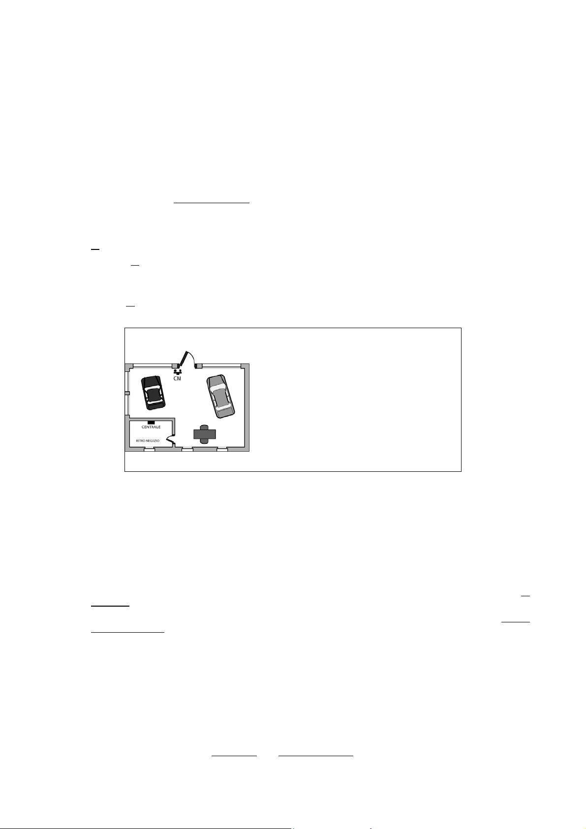
4.6.4 Bypass allowed
If an input is prearranged as an input with “bypass allowed”, the input will be subjected to either manual or automatic
exclusions.
For more details, see § 5.8 Inputs exclusion and inclusion and § 4.5.1 Arming mode – Standard / Autoexclusion / Block
arming.
4.6.5 Ancillary functions (Gong, Courtesy light, Door opening, Absence of move)
To burglar inputs, ancillary functions can be associated that can be used with system disarmed.
Ancillary functions can only work if all zones associated to input are not active.
For more details on single functions, see chapter 3 Alarms, Events and Signalling.
Each input can only have one out of following Ancillary functions:
None: no ancillary function armed.
Absence of move: when the system is disarmed
, the inputs enabled to this function are constantly checked; if within the
fixed time (12 hours, fixed) they do not send any state change, an Emergency alarm is generated. The timer is reset at
every input opening. The function is enabled only after an arm, followed by a disarm of zones associated to the inputs
that have this auxiliary function.
Gong: if all
the zones associated to the input are not active, the input opening generates a Gong event.
Courtesy light: if all the zones associated to the input are not active, the opening of an input associated to this function
generates a Courtesy light event. This function can be used, for example, to automatically turn the light on in a room or in a
way.
Door opening: if all
the zones associated to the input are not active, the input opening activates the door opener output
associated to the same zones.
Example of Gong function use
CM magnetic contact senses the opening of
the shop entrance door and it has been
programmed with Gong additional function.
During working hours, when the system is
disarmed, door opening is signalled by keypad
buzzer and arms outputs prearranged for Gong.
In this way, even if you are, in the office or at
the back of the shop, you will be informed that
someone is entering. When the system is
armed, the door opening will generate an
burglar alarm.
4.6.6 Burglar inputs attributes (Release type, AND / OR zones, AND inputs)
Burglar inputs operation mode can be further customized, by setting Release type.
• Release type, determines when the alarm signalling is generated. It is possible to choose between:
o Single release: alarm is generated as soon as the input is opened.
o Double release: alarm is generated at the end of the second event, only if it occurs within 120 second from the
first.
• Common input, means that the input is associated to more than one zone. It is possible to choose between:
o AND Zones: it logically connects the zones to which the input is associated and alarm is generated only if all
the zones are active.
o OR Zones: it logically connects the zones to which the input is associated and alarm is generated only if at least
one zone is active.
o AND inputs, it logically connects two burglar inputs with the same specialisation and alarm is generated only if
both of them are opened within 5 minutes from the first to the second (meanwhile the first opened input can also
be closed). It is not possible to change the interval of 5 minutes. AND inputs can be used, for example, to
reduce the possibility of false alarms issued from detectors installed in critical areas.
4.6.7 Input associated to a video camera
When Gateway Video 1067/450 is used, inputs have to be associated to cameras (up to 4 cameras are managed).
During operation, alarm event from an input associated to a video camera causes a set of images to be stored which will
be sent via email to email addresses defined on Gateway Video. For more detailed information, refer to Gateway Video
1067/450 Manuals.
Every input can be associated to one video camera only; each of the 4 video cameras can be associated to more inputs.
Inputs can be specialised with any type but Tamper
type and Technocogical type.
DS1067-035A 25 LBT8633
Page 26
4.6.8 Input programming
To program an input follow the instructions below:
1. Enter on keypad the installer code (default 000000) and press OK key.
2. Press MENU key.
3. Press ▼ key until “PROGRAMMING” appears on the display.
4. Press OK key to confirm.
5. Press ▼ key until “INPUTS” appears.
6. Press OK key to confirm. “CONTROL PANEL” appears.
7. Press OK key to confirm.
Select with ▼ key the desired input.
8. Press OK key to confirm.
9. Press ▼ key until “INPUT TYPE” appears. Press OK key to display the list of available
input types. Select the desired type with ▼ and ▲ keys and confirm it with OK.
10. Press ▼ key until “ASSIGN” appears.
11. Press OK key to confirm.
12. Press OK key to select SYSTEM and with ▼ and ▲ keys select DO NOT ASSIGN, in
order not to associate the input to any zone, or ASSIGN to associate it to all the zones, by
confirming selection with OK key. Otherwise it is possible to associate to the input the
single zones by pressing ▼ key when appears the image of step 11, until “ZONES”
appears.
13. Press OK key to confirm.
Select desired zones and press OK key to confirm.
14. Press ESC key until “ASSIGN” appears again.
15. Press ▼ key until “CUSTOMIZE” appears. Press OK key to display the configurations of
available inputs. Select desired configuration with▼ and ▲ keys and confirm it with OK
key.
16. If “Delayed burglar” configuration is selected, a new additional item concerning the delay
time of every input will appear. Select delay time by keys ▼ e ▲. (5s, 10s, 30s, 1m,
1m30s, 5m, 20s).
17. Press▼ key until “BYPASS ALLOWED” appears on the display.
With▼ and ▲ keys select “DISABLE”, to disable exclusion possibility, or “ENABLE” to
enable it, by confirming selection with OK key.
18. Press▼ key until “ANCILLARY FUNCT” appears on the display.
Press OK key to select additional functions “NONE”, “ABSENCE OF MOVE”, “GONG”,
“COURTESY LIGHT”, “DOOR OPENING”. Select the desired additional function with
19. Press▼ key until ”ATTRIBUTES” appears on the display.
20. Press OK key. With ▼, ▲ and OK keys it is possible to select and configure
characteristics RELEASE TYPE (Single or double) and “COMMON INPUT " (AND zones or
OR zones). It is possible to configure both attributes types. At the end press ESC key to
return to “ATTRIBUTES”.
21. Press▼ key until “VIDEO ASSIGN” appears on the display (This is an optional feature
used only if the system is connected to the Videogateway). Press the OK key to display
which of the 4 Videogateway cameras is assigned to the input. The available options are:
DISABLED (no camera assigned) CAMERA 1, 2, 3, or 4. Select the desired camera with
the ▼ and ▲ keys and confirm with OK.
22. Press▼ key until “AND INPUTS” appears on the display.
OK key.
UT00:INSTALLER
PROGRAMMING
PROGRAMMING
INPUTS
INPUTS
CONTROL PANEL
CONTROL PANEL
UC.In1: In01
UC.In1: In01
INPUT TYPE
UC.In1: In01
ASSIGN
ASSIGN
SYSTEM
ASSIGN
ZONE
ZN01:...
□□□□□□
UC.In1: In01
CUSTOMIZE
DELAY
5s
UC.In1: In01
BYPASS ALLOWED
UC.In1: In01
ANCILLARY FUNCT
UC.In1: In01
ATTRIBUTES
ATTRIBUTES
RELEASE TYPE
UC.In1: In01
ATTRIBUTES
UC.In1: In01
VIDEO ASSIGN
UC.In1: In01
AND INPUTS
DS1067-035A 26 LBT8633
Page 27
23. Press Ok key. “DISPLAY AND” appears. With ▼, ▲ and OK keys it is possible to display
(DISPLAY AND) the AND connections of the input or it is possible to select (SELECT
AND) to which other input can be connected the input, or disable (DISABLE AND) the AND
connection, if present. At the end press ESC key to return to “AND INPUTS”.
24. Press▼ key until “NAME” appears on the display.
25. Press OK key to confirm.
Give the input a descriptive name, by using the keypad (for further information see
paragraph 4.2 Alphanumeric characters input). Name maximum length is 10 digits.
26. Press OK key to confirm. “NAME” appears again.
27. Program the other control panel inputs by following the same procedure from step 7.
28. If the system has expansions, keypads or key readers, press ESC key until “CONTROL
PANEL” appears again on the display.
29. Press ▼ key to display the desired peripheral type (EX, KP, DK) ) and confirm selection by
pressing OK key, then program all its inputs with the same procedure used for control
panel inputs programming.
30. Program all the inputs and at the end press ESC repeatedly to exit from the menu.
AND INPUTS
DISPLAY AND
UC.In1: In01
AND INPUTS
UC.In1: In01
NAME
NAME
In01:...
INPUTS
CONTROL PANEL
INPUTS
EXPANSIONS
4.7 WIRED OUTPUTS PROGRAMMING
System 1067 manages max general use 15 outputs.
For more information and connections refer to Installation manual.
4.7.1 Outputs encoding
Every output has two addresses: a physical one and a logical one. The two addresses are displayed according to the
following diagram:
physical address : logical address
more in detail
ddXX UY:UZZ
where:
– dd is the bus device type or the control panel (UC=control panel, EW=expansion)
– XX is the progressive numbering of bus devices that contain the outputs
– Y is the output numbering in bus X device.
– ZZ is the output logical address, composed by two digits, that the control panel assigns with a system progressive
numbering when bus devices are acquired.
The physical address is useful for the installer during system installation and maintenance phase.
System 1067 identifies the outputs on display with physical, logical address and name. During acquisition phase of
1067/008 expansions, the control panel assigns automatically a progressive logical address, in sequence, to the control
panel outputs.
4.7.2 Outputs types
With the programming procedure it is possible to change outputs physical characteristics.
Possible outputs types are:
• Not used: it disables the outputs.
• Output N.L.: at rest condition, if output is a relay output, the relay is de-energised;
if output is an electric output, the output is open (lack of electric potential).
• Output N.H.: at rest condition, if output is a relay output, the relay is excited;
if output is an electric output with positive reference, the output has 12 V level;
if output is an electric output with negative reference, the output has 0 V level.
For a detailed analysis of relay and electric outputs operating mode, when they are set as N.L. or N.H., refer to
Installation manual.
DS1067-035A 27 LBT8633
Page 28
4.7.3 Outputs specialisations
Control panel and expansion outputs, both relay and electric, can be programmed to be activated after specific events.
For more details on single functions, see chapter 3 Alarms, Events and Signalling.
Possible specialisations for outputs are described below.
O BURGLAR
Burglar outputs are armed if an burglar alarm is generated.
O PRE-ALARM
Pre-alarm outputs are armed if a Pre-alarm is generated.
O TAMPER
Tamper outputs are armed if a Tamper alarm or a Wrong code alarm are generated.
O BURGLAR / TAMPER
Burglar/Tamper outputs are armed if a Burglar alarm or a Tamper alarm or a Wrong Code alarm is generated.
O BURGLARY RESET
Burglary Reset outputs are pulse armed for approximately 1 second at zones arming.
O AUDIBLE PANIC
Panic outputs are armed if a Panic alarm is generated.
O SILENT PANIC
Silent Panic outputs are armed if a Silent Panic is generated.
O HOLD-UP
Hold-up outputs are armed if a Hold-up alarm is generated.
O FIRE
Fire outputs are armed if a Fire alarm is generated.
O FIRE RESET
Fire reset outputs are armed if a fire reset input is opened.
O EMERGENCY
Emergency outputs are armed if a Emergency alarm is generated.
O TECHNOLOGICAL TYPE 1 (STATE)
Technological outputs are armed if a Technological event is generated.
O COMMANDABLE
activated if...
• an output arm command Is performed by the timing programmer
• an arm command via SMS is performed
• an output arm command by user remote management Is performed, by entering the correct
DTMF sequence
• the control panel is called, by GSM channel, by the telephone number to which the No Cost
Call function has been associated
• remote control key “+” is pressed
deactivated if...
• is performed an output disarm command
O PULSE U COM.
activated if...
• an output arm command Is performed by the timing programmer
• an arm command via SMS is performed
• an output arm command by user remote management Is performed, by entering the correct
DTMF sequence
• the control panel is called, by GSM channel, by the telephone number to which the No Cost
Call function has been associated
• remote control key “+” is pressed
is held...
• about 1 second
DS1067-035A 28 LBT8633
Page 29
O DOOR OPENING
Outputs Door Opening are armed if a Door Opening event is generated.
O COURTESY LIGHT
Courtesy light outputs are armed if a Courtesy light event is generated.
O FAILURE
Failure outputs are armed if an alarm is generated by a respective Failure input.
O TELEPHONE FAILURE
Telephone failure outputs are armed if a Telephone failure alarm is detected.
O SYSTEM FAILURE
System failure outputs are armed if a system failure alarm is generated.
O LACK OF POWER
Lack of power outputs are armed if a lack of power event is detected.
O LOW BATTERY
Low battery outputs are armed if a low battery event is detected.
O ZONES STATUS
activated if...
deactivated if...
• all the zones associated to it are active (AND zones)
• all the zones associated to it are not active
O AND TC
activated if...
deactivated if...
• all the zones associated to it are active
• at least one of the zones associated to it is not active
O OR TC
activated if...
deactivated if...
• At least one of the zones associated to it is active
• all the zones associated to it are not active
HOW TO USE TC OUTPUTS
TC (Trigger Control) output is used to control detectors, sirens and other signalling devices; as an example it is used to
put them to stand-by status; it is conditioned by zones status.
TC AND output implies that all associated zones are active in order that output is activated.
For TC OR output, it is sufficient that one zone out of associated zones is active in order that output is activated.
Warning: TC output is default setting as NL and with the Jumper polarization on the “-”; so when it is a rest, it
provides a low level (0V). This is a condition that places Urmet detectors on stand-by (block on the S Input).
O OPEN INPUT
activated if...
deactivated if...
• at least one of the inputs in a zone associated to this output is opened
• all the inputs in the zones associated to this output are closed
O EXCL. INPUT
activated if...
• is excluded at least one of the inputs in a zone associated to this output, manually or with self
by-pass at activation or owing to its alarm count overflow
deactivated if...
• are included all the inputs in the zones associated to this output
O BUZZER
activated...
• in slow intermittent mode during associated zone Exit time
• in fast intermittent mode during associated zone Entry time
is held...
• for associated zone Entry/Exit time
O ARM WARNING
activated if...
• is started the Warning time programmed for a zones arm command given by the timing
programmer
is held...
• for the Warning time
O GONG
activated if...
• is opened an input with Gong additional function enabled, included in a zone also associated
to the output. All the zones associated to the input must be deactivated.
is held...
is signalled...
• 1 second
• by the keypads buzzer (if programmed)
DS1067-035A 29 LBT8633
Page 30
4.7.4 Output programming
To program an output follow the instructions below:
1. Enter on keypad the Installer code (default 000000) and press OK key.
2. Press MENU key.
3. Press ▼ key until “PROGRAMMING” appears on the display.
4. Press OK key to confirm.
5. Press ▼ key until “OUTPUTS” appears.
6. Press OK key to confirm. Select with the ▼ key if programming the control panel outputs
or those of any expansion configured.
7. Press OK key to confirm.
Select with ▼ key the desired output.
8. Press OK key to confirm.
9. Press OK key and after ▼ key until “OUTPUT TYPE” appears.
10. Press OK key to display the types of available outputs (N.L. – N.H. – Not used). Select
desired type with▼ and ▲ keys and confirm it with OK key.
11. Press ▼ key until “ASSIGN” appears.
12. Press OK key to confirm.
13. Press OK key to select SYSTEM and with ▼ and ▲ keys select “DO NOT ASSIGN”, in
order not to associate the output to any zone, or “ASSIGN” to associate it to all the zones,
by confirming selection with OK key.
14. Otherwise it is possible to associate to the output the single zones by pressing ▼ key until
“ZONES” appears.
15. Press OK key to confirm.
Select desired zones and press OK key to confirm
16. Press repeatedly ESC key until “ASSIGN” - “ZONES” appears again.
17. Press ▼ key until “CUSTOMIZE” appears.
18. Press OK key to display the configuration of available outputs. Select desired configuration
▼ and ▲ keys and confirm it with OK key.
with
19. Press▼ key until “NAME” appears on the display.
20. Press OK key to confirm.
Give the output a descriptive name, by using the keypad (for further information see
paragraph 4.2 Alphanumeric characters input).
21. Press OK key to confirm. “NAME” appears again.
22. Program the other control panel outputs by following the same procedure from point 7.
23. If the system has expansions, press ESC key until “CONTROL PANEL” appears again on
the display.
24. Press ▼ key to display “EXPANSIONS”.
Confirm by pressing OK key, select the desired expansion with ▼ and ▲ keys, confirm
selection by pressing OK key, then program all its outputs with the same procedure used
for control panel outputs programming.
25. Program all the expansions and at the end press ESC repeatedly to exit from the menu
NOTE: commandable outputs maximum number is 10. The logical address of these outputs must be from 01 to 10.
UT00:INSTALLER
PROGRAMMING
PROGRAMMING
ZONES
PROGRAMMING
OUTPUTS
OUTPUTS
CONTROL PANEL
CONTROL PANEL
UC.U1: U01
UC.U1: U01
OUTPUT TYPE
UC.U1: U01
ASSIGN
ASSIGN
SYSTEM
ASSIGN
ZONES
ZN01:...
□□□□□□
UC.U1: U01
CUSTOMIZE
UC.U1: U01
NAME
NAME
U01:...
UC.U1: U01
NAME
OUTPUTS
CONTROL PANEL
OUTPUTS
EXPANSIONS
DS1067-035A 30 LBT8633
Page 31
4.8 KEYPADS PROGRAMMING
To program a keypad follow the instructions below:
1. Enter on the keypad the Installer code (default 000000) and press OK key.
2. Press MENU key.
3. Press ▼ key until “PROGRAMMING” appears on the display.
4. Press OK key to confirm.
5. Press OK key to confirm.
6. Press OK key to confirm.
7. Press ▼ and ▲ keys to select the desired keypad.
8. Press OK key to confirm.
9. Press OK key to confirm.
10. Press OK key to select “SYSTEM” and with ▼ and ▲ keys select “DO NOT ASSIGN”, in
order not to associate the keypad to any zone, or “ASSIGN” to associate it to all the zones,
by confirming the selection with OK key.
11. Otherwise the single zone can be associated to the keypad, by pressing ▼ key, when the
image of step 7 appears, until “ZONES” is shown.
12. Press OK key to confirm.
Select desired zones and press OK key to confirm.
13. Press ESC key repeatedly until “ASSIGN” appears again.
14. Press ▼ key until “GONG FUNCTION” appears. Press OK key and with ▼ and ▲ keys
choose if gong audio signal emitted by the keypad buzzer is enabled or disabled, by
confirming selection with OK key.
15. Press ▼ key until “SOUND TIME ENTRY” appears.
16. Press OK key and with ▼ and ▲ keys choose if entry time audio signal with keypad
buzzer is enabled or disabled, by confirming selection with OK key.
17. Press ▼ key until “SOUND TIME EXIT” appears.
18. Press OK key and with ▼ and ▲
keypad buzzer is enabled or disabled, by confirming the selection with OK key.
19. Press key ▼ until “ENVIR. LISTENING” appears.
Press OK key and use keys ▼ and ▲ to choose whether enable or disable automatic
listening at the end of an emergency call, confirming the choice by OK key.
NOTE 1: By enabling this function, it is determined that, in the case of a call for Emergency
Alarm activated by an Emergency input or owing to lack of movement, at the end of sending
pre- recorded vocal message, the system automatically activates listening from this vocal
keypad. If more vocal keypads are present, this function must only
keypad from which automatic listening is preferred to occur. Called user can conse quently
listen, from his/her phone, the voices and noise from the environme nt where the keypad is
located; as an example, the environment might be the living room; through DTMF commands
(see 5.6.6) it can be switch to listen on other keypads if the system is provided with them.
NOTE 2 if emergency alarm was activated by pressing a keypad function key, automatic
listening at end of call is directly from this keypad independently of “ENVIR. LISTENING”
programming.
20. Press ▼ key until “MASKING” appears.
Press OK key and with ▼ and ▲ keys choose if system state masking on display is
enabled or disabled, for not authorized people
OK key. Masking hides active and not active zones display; zones will be visible only after
entering a valid code.
21. Press ▼ key until “NAME” appears.
22. Select with OK key.
Give the keypad a descriptive name, by following the information in paragraph 4.2
Alphanumeric characters input.
keys choose if the exit time acoustic signalling with the
be activated for that
(see § 5.2.8), by confirming selection with
Us00:INSTALLER
PROGRAMMING
PROGRAMMING
ZONES
PROGRAMMING
KEYPADS
KEYPADS
KP01:KP 01
KP01:KP 01
ASSIGN
ASSIGN
SYSTEM
ASSIGN
ZONES
ZN01:...
□□□□□□
KP01:KP 01
GONG FUNCTION
KP01:KP 01
SOUND TIME ENTRY
KP01:KP 01
SOUND TIME EXIT
KP01:KP 01
ENVIR.LISTENING
KP01:KP 01
MASKING
KP01:KP 01
NAME
NAME
KP01:KP 01
DS1067-035A 31 LBT8633
Page 32
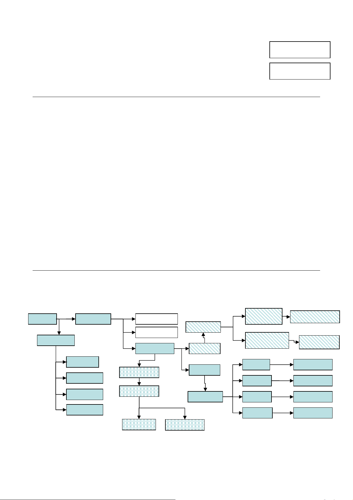
23. Press key ▼ until “FUNCTION KEYS” appears. Press OK key and use keys ▼ and ▲ to
enable or disable function keys “Fire”, “Silent panic” and “Emergency” (see § 5.3),
confirming choices by OK key.
24. Program the other keypads by following the same procedure from step 7; otherwise, press
ESC repeatedly to exit from the menu.
KP01:KP 01
FUNCTION KEYS
FUNCTION KEYS
FIRE
4.9 READERS PROGRAMMING
Following programming is provided for readers:
• Association to Zones: the LEDs of each key reader can be freely associated to one or more System zones.
It is not possible to associate the same zone to more LEDs of the same key reader.
The key reader operates on zones associated to its 3 LEDs:
- total arm performed from that key reader corresponds to the arm of all zones associated to that key reader;
- every green LED displays the status of associated zones (see § 2.2);
- through yellow LED, only open inputs and alarms concerning associated zones are displayed.
• Masking: masking allows to enable the masking of system status on the reader (see § 5.2.8). Masking inhibits key
reader LED signalling, which will only become visible at inserting a valid key.
To program an electronic or proximity key reader, access, from Technician menu «PROGRAMMING» / «READERS».
Then select the number of reader to be programmed.
Reader submenu is then accessed where there can be configured:
• «ASSIGN »
o «LED 1» to associate reader LED 1 to zones
o «LED 2» to associate reader LED 2 to zones
o «LED 3» to associate reader LED 3 to zones
Close to LED numbering there is graphically indicated LED position on key reader.
□ = not associated zone
■ = associated zone
By keys ◄ and ► you can move through zones; you can either associate or not associate the zone you are positioned
on by pressing keys ▼ and ▲. At the end, press OK key to confirm; the system will associate the key reader to
preselected zones.
• «MASKING» choose whether enable or disable system status masking on reader.
• « NAME » you can give a description name max 24 characters long to connector (see § 4.2).
4.10 RADIO DEVICES PROGRAMMING
Like previously described for wired devices as concerns input and output programming, radio device programming too is
modelled on the same architecture, to which have been added specific menus relevant to radio devices and remote
control. Below, the programming menu flowchart, already present in 1067, control panel, shows the plug-in level from
the new branch, improved with all the parameters that can be selected on each peripheral:
INSTALLER
TEST
MAINTENANCE
TEST INPUTS
TEST OUTPUTS
BATTERY
ADVANCED
ACQUIRE
DELETE
RADIO DEVICES
CONFIGURATION
SELECT EW 01
SUPERVISION
SELECT EW 01
JAMMING
ACQUIRE
DELETE
SELECT EW 01
SELECT
ACQUIRE
INPUT DEVICES
SELECT
ACQUIRE
SELECT IR
SELECT DC
SELECT RC
SELECT SIR
ACQUIRE
IR/DC/RC IN PROGESS
ACQUIRE SIRENS
IN PROGESS
DELETE IR
DELETE DC
DELETE RC
DELETE SIR
NOTE: function av ailable with 1067 control panel and 1 067/021 keypads, software version 3.00 or higher and with an
1067/010 radio expansion.
DS1067-035A 32 LBT8633
Page 33
4.10.1 Radio inputs encoding
Every input has two codes: a physical one and a logical one. The two addresses are displayed according to the following
diagram:
physical address : logical address
more in detail:
ddXX InY: InZZ
where:
• dd is the radio device type associated with a1067/010 (IR, DC, RC)
• XX is the progressive numbering of radio devices acquired by type
• Y is the input numbering in radio X device (physical address)
• ZZ is the input logical address, that the control panel assigns with a system progressive numbering when radio
devices are acquired.
The physical address is useful for the installer during system installation and maintenance phase. On display may appear
with another notation (EW= radio expansion, IR= infrared detector, DC= micro contact/Door Contact).
The installer can change the logical address at any time.
System 1067 identifies the inputs on display with physical address, logical address and name, while voice and numerical
alarms are identified only with logical address and customized message, if present.
During acquisition phase of 1067/010 radio expansion, the control panel assigns automatically a progressive logical
address to all the inputs, while microcontacs auxiliary inputs are not considered because they are default inputs and
consequently they are defined as not used and must be manually enabled and numbered (max 32 for each 1067/010).
Warning: please notice that the 1067 system controls max. 32 inputs. All control panel and expansion inputs are
factory-setting, whereas the auxiliary inputs of keypads, readers and DC devices are “Not Used”. Therefore,
should there be installed several 1067/008 expansions and at least one 1067/010, expansion and you want to use
certain auxiliary inputs then, it will be necessary to disarm the same number of inputs in order to stay within the
total number of 32 inputs.
For more information and connections, refer to Installation manual.
4.10.2 Inputs type
1067/010 radio expansion defines the input type according to two types:
•
Not Used: electric signal changes, both as input opening and tamper, are ignored. By programming an input as “Not
used”, the logical address of the device will be deleted (
exist.
• Used: default setting, input is coded like previously described, signal changes, both as input opening and tamper,
will arm the event assigned to it.
Warning: The auxiliary contact of the Micro-contact is automatically defined as “not used” and therefore for using
it, it shall be coded manually, both at control panel level and individual level via the DIP SWITCH configuration
onboard the device.
4.10.3 Radio input customizations
Alarm input configuration specifies how, when and what type of alarm is generated. According to the type of generated
alarm, the control panel will activate the specific devices (outputs, sirens and communicator).
For further details about each function see chapter 3 Alarms, Events and Signalling.
The table below lists the available customizations, according to the type of input:
Device 1058/101 1058/201
Value Reed contact Aux contact
Customizations
Immediate (default) Immediate (default)
Delayed Delayed Delayed
Pre-alarm Pre-alarm Pre-alarm
For complete description relevant to the multiple customizations applicable to radio inputs, refer to the description
provided at the paragraph dealing with wired devices since it is the same one § 4.6.3 – Wired input customizatio.n
InNN). Pratically a door contact having this type does not
Immediate
DS1067-035A 33 LBT8633
Page 34
4.10.4 Radio input attributes: Bypass allowed, Release type, Common input, AND inputs
The table below lists the available programming, according to the type of input:
Device 1058/101 1058/201
Programming Value Reed contact Aux contact Notes
Bypass allowed
Release type
Common input
AND Inputs
For complete description relevant to the multiple attributes applicable to radio inputs, refer to the description provided at
the paragraph dealing with wired devices since it is the same one: § 4.6.4 Bypass allow ed and; § 4.6.6 Burglar inputs
attributes.
4.10.5 Radio ancillary functions (Gong, Courtesy light, Door opener, Absence of move)
The table below lists the available programming, according to the type of input:
Device 1058/101 1058/201
Programming Value Reed contact Aux contact Notes
Ancillary
functions
For complete description relevant to the ancillary functions applicable to radio inputs, refer to the description provided
at the paragraph dealing with wired devices since it is the same one: § 4.6.5 – Ancillary functions.
4.10.6 Assigning a radio input to a videocamera
The table below lists the available programming, according to the type of input:
Device 1058/101 1058/201
Programming Value Reed contact Aux contact Notes
Video assign
For complete description relevant to the assignment of a videocamera applicable to radio inputs, refer to the description
provided at the paragraph dealing with wired devices since it is the same one: § 4.6.7 – Input associated to a video
camera.
4.10.7 Radio input programming
To program an radio input follow the instructions below:
1. Enter on the keypad the Installer code (default 000000) and press OK key.
2. Press MENU key.
3. Press ▼ key until “PROGRAMMING” appears on the display.
4. Press OK key to confirm.
5. Press ▼ key until “RADIO DEVICES” appears.
6. Press OK key to confirm. “EW01:EW01” appears.
7. Press OK key to confirm. Press ▼ key to select the desired type of device (IR; DC)
Bypass not allowed Bypass not allowed Bypass not allowed
Bypass allowed (default) Bypass allowed (default) Bypass allowed (default)
Single Single Single
Double Double Double
AND zones AND zones AND zones
OR zones OR zones OR zones
(default)
Do not assign
another input
Assign another input Assign another input Assign another input
None (default) None (default) None (default)
Door opener Door opener Door opener
Courtesy light Courtesy light Courtesy light
Absence of move Absence of move Absence of move
Gong Gong Gong
Do not assign (default) Do not assign (default) Do not assign (default)
Video No. Video No. Video No.
(default)
Do not assign
another input
(default)
Do not assign
another input
Only one of these
Each of these
attributes can be
programmed
individually
The other
assigned input
must feature
the same
customization
functions can be
assigned.
Can only be
used if video
gateway
is provided
UT00: INSTALLER
PROGRAMMING
PROGRAMMING
RADIO DEVICES
RADIO DEVICES
EW01:EW01
EW01:EW01
SELECT DC
DS1067-035A 34 LBT8633
Page 35
8. Press OK key to confirm. Select with ▼ key the desired input (DC01;DC02 etc.)
9. Press OK key to confirm. Press ▼ key to select the desired type of input
10. Press OK key to confirm.
11. Press ▼ key until “INPUT TYPE” appears. Press OK key to display the list of
available input types. Select the desired type with ▼ and ▲ keys and confirm it with
OK.
12. Press ▼ key until “ASSIGN” appears.
13. Press OK key to confirm.
14. Press OK key to select SYSTEM and with ▼ and ▲ keys select DO NOT ASSIGN,
in order not to associate the input to any zone, or ASSIGN to associate it to all the
zones, by confirming the selection with OK key. Otherwise it is possible to associate
to the input the single zones by pressing ▼ key when appears the image of step 11,
until “ZONES” appears.
15. Press OK key to confirm.
16. Select desired zones and press OK key to confirm.
17. Press ESC key repeatedly until “ASSIGN” appears again.
18. Press ▼ key until “CUSTOMIZE” appears. Press OK key to display the
configurations of available inputs. Select desired configuration with▼ and ▲ keys
and confirm it with OK key.
19. If “Delayed burglar” configuration is selected, a new additional item concerning the
delay time of every input will appear. Select delay time by ▼ and ▲ keys. (Disabled,
10s, 30s, 1m, 1m30s, 5m, 20s).
20. Press ▼ key until “BYPASS ALLOWED” appears.
With▼ and ▲ keys select “DISABLE”, to disable exclusion possibility, or “ENABLE”
to enable it, by confirming selection
21. Press ▼ key until “ANCILLARY FUNCT.” appears
22. Press OK key to select additional functions NONE, ABSENCE OF MOVE, GONG,
COURTESY LIGHT, DOOR OPENER. Select the desired additional function with OK
key.
23. Press ▼ key until”ATTRIBUTES” appears.
24. Press OK key. With ▼, ▲ and OK keys it is possible to select and configure the
attributes RELEASE TYPE (Single or double) and COMMON INPUT (Zones AND or
Zones OR). It is possible to configure both characteristics types. At the end press
ESC key to return to “ATTRIBUTES”.
25. Press ▼ key until “AND INPUTS” appears.
26. Press OK key. “DISPLAY AND” appears. With ▼, ▲ and OK keys it is possible to
display (DISPLAY AND) the AND connections of the input or it is possible to select
(SELECT AND) to which other input can be connected the input, or disable
(DISABLE AND) the AND connection, if present. At the end press ESC key to return
to “AND INPUTS”.
27. Press ▼ key until “NAME” appears.
with OK key.
SELECT DC
DC01:...
DC01:...
DC01.In01: In01
DC01.In01: In01
INPUT TYPE
DC01.In01: In01
ASSIGN
ASSIGN
SYSTEM
ASSIGN
ZONES
ZN01:...
□□□□□□
DC01.In01: In01
CUSTOMIZE
DELAY
5s
DC01.In01: In01
BYPASS ALLOWED
DC01.In01: In01
ANCILLARY FUNCT.
DC01.In01: In01
ATTRIBUTES
ATTRIBUTES
RELEASE TYPE
DC01.In01: In01
ATTRIBUTES
DC01.In01: In01
AND INPUTS
AND INPUTS
DISPLAY AND
DC01.In01: In01
AND INPUTS
DC01.In01: In01
NAME
DS1067-035A 35 LBT8633
Page 36

28. Press OK key to confirm.
Give the input a descriptive name, by using the keypad (for further information see §
4.2). Name maximum length is 10 digits.
29. Press OK key to confirm. “NAME” appears.
30. Program the other 1067/010 expansion inputs by following the same procedure from
step 6.
31. At the end press ESC repeatedly to exit from the menu.
4.10.8 Radio output programming (SIRENS)
The 1067 system controls max. 15 general purpose outputs; a single radio expansion (1067/010) can contextually
control just two outputs (sirens).
4.10.9 Radio output coding
Every input has two codes: a physical one and a logical one. The two addresses are displayed according to the following
diagram:
logical address: physical address
more in detail
NAME
In01:...
RADIO DEVICES
EW01:EW01
ddXX UY: UZZ
dove:
• dd is the radio device type associated to an 1067/010
• XX is the progressive numbering of radio devices acquired as inputs
• Y is the input numbering in radio XX device (physical address)
• ZZ is the input logical address, composed by two digits, that the control panel assigns with a system progressive
numbering when radio devices are acquired.
The physical address is useful for the installer during system installation and maintenance phase. On display may appear
with another notation (EW= radio expansion, HP= external sirena).
The output customizations define the sirens programming, in order to be activate for a specific events.
System 1067 identifies the inputs on display with physical address, logical address and name, while vocal or numerical
alarms are identified only with logical address and customized message, if present.
During acquisition phase of 1067/010, expansions, the control panel assigns automatically a progressive logical
address in sequence, to the control panel outputs and eventual other 1067/008 expansion outputs.
4.10.10 Radio output customizations
The output customizations define the sirens programming, in order to be activate for a specific events.
For more details on single functions, see Chapter 3 Alarms, Events and Signalling.
The table below lists the customizations available for the sirens:
Device Radio siren
Burglar (default)
Pre-alarm
Customizations
For complete description relevant to the only customizations applicable to radio outputs, refer to the description
provided at the paragraph dealing with wired devices since it is the same one: § 4.7.3 – Output customizations.
4.10.11 Status report
The table below lists the available applicable functions:
Device Radio siren
Status report
For further details concerning the “Status report” function please refer to § 3.2 Acoustic Signalling.
Tamper
Audible panic
Fire alarm
Disabled (default)
Blinking only
Siren + blinking
DS1067-035A 36 LBT8633
Page 37
4.10.12 Radio output programming
To program an radio output follow the instructions below:
1. Enter on keypad the Installer code (default 000000) and press OK key.
2. Press MENU key.
3. Press ▼ key until “PROGRAMMING” appears on the display.
4. Press OK key to confirm.
5. Press ▼ key until “RADIO DEVICES” appears on the display.
6. Press OK key to confirm. Select with ▼ keys the radio expansion
7. Press ▼ key until “SIRENS” appears on the display. Press OK key to confirm.
8. Select with ▼ key the desired function “SELECT SIREN”.
9. Press OK key to confirm. Select with ▼ key the siren (1058/405).
10. Press OK key to confirm.
11. Press ▼ key until “NAME” appears on the display.
12. Press OK key to confirm.
13. Give the output a descriptive name, by using the keypad (for further information see
§ 4.2).
14. Press OK key to confirm. “NAME” appears.
15. Go back to the upper level by pressing ESC key.
Select the “ASSIGN” function by ▼ and ▲ key, and confirm with OK key.
16. Press OK key to select “SYSTEM” and with ▼ and ▲ keys select “DO NOT
ASSIGN”, in order not to associate the output to any zone, or “ASSIGN” to associate
it to all the zones, by confirming selection with OK key.
17. Otherwise it is possible to associate to the output the single zones by pressing ▼ key
until “ZONES” appears.
18. Press OK key to confirm.
19. Select desired zones and press OK key to confirm.
20. Press
21. Press ▼ key until “CUSTOMIZE ” appears on the display.
22. Press OK key to display the configuration of available outputs. Select desired
23. Program any other expansion by following the same procedure from point 7.
24. At the end press ESC repeatedly to exit from the menu.
ESC key until “ASSIGN” appears again.
configuration with▼ and ▲ keys and confirm it with OK key.
UT00:INSTALLER
PROGRAMMING
PROGRAMMING
RADIO DEVICES
RADIO DEVICES
EW01:EW01
EW01:EW01
SIRENS
SIRENS
SELECT SIREN
SELECT SIREN
HP01:...
HP01. U01
NAME
NAME
U01:...
HP01. U01
NAME
SIRENS
ASSIGN
ASSIGN
SYSTEM
ASSIGN
ZONES
ZN01:...
□□□□□□
SIRENS
CUSTOMIZE
4.11 1058/035 REMOTE CONTROL PROGRAMMING
The flowchart below shows the remote control programming flow once acquired from the 1067 control panel.
In order to allow intuitive and friendly reading of the flowchart, the menu has been represented like it actually appears on
the keypad display, navigation and confirmation keys have also been represented in order to lead the installer step by
step during the programming phase.
For further details concerning the use of the keypad, please refer to the descriptions and drawings contained in
paragraph 2.1 1067/021 Keypad display.
NOTE: function available with 1067 control panel and 106 7/ 021 k eyp ads, software 3.00 or hi gher and w ith an 1067/0 10
radio expansion.
DS1067-035A 37 LBT8633
Page 38
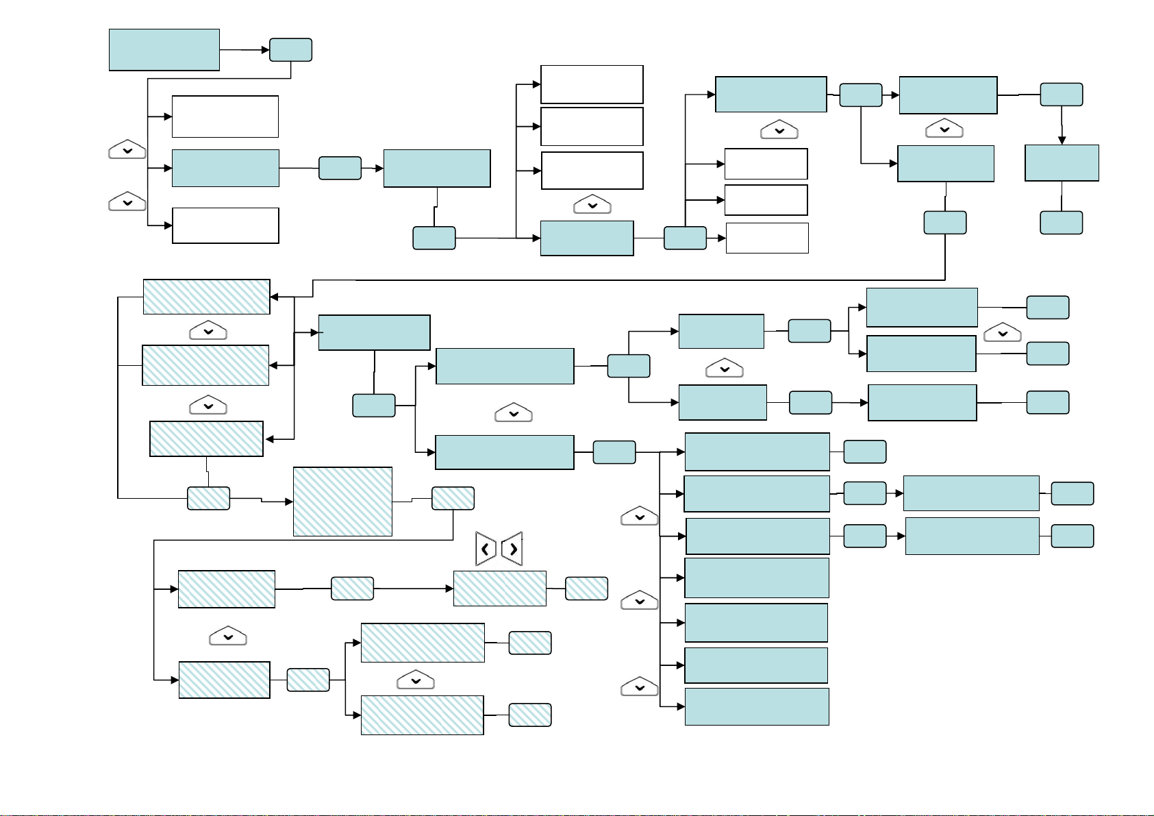
UT00:INSTALLER
PROGRAMMING
PROGRAMMING
READERS
PROGRAMMING
RADIO DEVICES
PROGRAMMING
ADVANCED
OK
OK
EW01:EW 01
SELECT IR
EW01:EW 01
SELECT DC
RADIO DEVICES
EW01:EW 01
OK OK
EW01:EW 01
SIRENS
EW01:EW 01
SELECT RC
SELECT RC
RC01:…
SELECT RC
RC02:…
SELECT RC
RC03:…
SELECT RC
RC04:…
OK
RC01:…
NAME
RC01:…
KEYS PROGR.
OK
OK
NAME
RC01:…
OK
KEYS PROGRAM.
1 ARM
KEYS PROGRAM.
3 TOGGLE
KEYS PROGRAM.
4 DISARM
OK OK
ASSIGN
ZONES
ASSIGN
SYSTEM
KEYS PROGRAM.
2 GENERIC
OK
1………………..
3………………..
4 DISARM
ASSIGN
OK OK
OK
2 GENERIC
ASSIGN
2 GENERIC
COMMAND TYPE
SYSTEM
DO NOT ASSIGN
SYSTEM
ASSIGN
ZN01:...
□□□□□□□□
OK
OK
OK
OK
ASSIGN
SYSTEM
ASSIGN
ZONES
COMMAND TYPE
NOT USED
COMMAND TYPE
ARM (ENABLE)
COMMAND TYPE
DISARM (DISABLE)
COMMAND TYPE
SILENT PANIC
COMMAND TYPE
AUDIBLE PANIC
COMMAND TYPE
EMERGENCY
COMMAND TYPE
FIRE ALARM
OK
OK
SYSTEM
DO NOT ASSIGN
SYSTEM
ASSIGN
ZN01:...
□□□□□□
OK
OK
OK
ARM (ENABLE)
U03:…
DISARM (DISABLE)
U12:…
OK
OK
OK
OK
OK
Page 39
4.12 ADVANCED PROGRAMMING
4.12.1 Remote management system code setting
To set the system code used for remote management with FastPro 1067/001 software, follow the instructions below:
1. Enter on the keypad the Installer code (default 000000) and press OK key.
2. Press MENU key.
3. Press ▼ key until “PROGRAMMING” appears on the display.
4. Press OK key to confirm.
5. Press ▼ key until “ADVANCED” appears.
6. Press OK key to confirm.
Press ▼ key until “ADVANCED” appears.
7. Press OK key to confirm. The system code appears. Enter the new code, with 8 digits.
8. Press OK key to confirm the code and then ESC key repeatedly to exit from the menu.
UT00:INSTALLER
PROGRAMMING
PROGRAMMING
ZONES
PROGRAMMING
ADVANCED
ADVANCED
SYSTEM CODE
SYSTEM CODE
99999999
4.13 SYSTEM GENERAL PARAMETERS - TIMING
The system general parameters that can be configured are the following:
• Burglar / Tamper / Panic alarm time: it is the activation time of alarm outputs (for example the siren sound time) for
burglar, tamper and panic alarms. It is possible to select: 30, 60, 90, 180 seconds and 9 minutes
• Pre-alarm time: it is the activation time of pre-alarm outputs (for example siren sound time). It is possible to select:
30, 60, 90, 180 seconds and 9 minutes.
• Emergency alarm time: it is the activation time of outputs (for example siren sound time) for emergency alarms. It is
possible to select: 30, 60, 90, 180 seconds and 9 minutes.
• Alarms count: it is the number of alarm repetitions allowed to each excludible burglar input, also when new alarms
are present; “DISABLED” means that alarm warnings will be generated at each new event. The function is useful to
prevent the detector from sending out an excessive number of alarms during an arming cycle, so disturbing the
peace.
The values that can be selected are: DISABLED, 2, 4, 6 and 8.
Limit selected is the only one throughout the system and alarms count is performed for each excludible burglar input.
When the count involving an input has reached limit set, that input is automatically excluded; the event is recorded to
historic file (and relating keypads LED goes on).
The alarms count of each input is reset:
o when all zones associated to it with function AND are disarmed
o when at least one zone associated to it with function OR is disarmed
o when time 24.00 is being passed.
• Lack of power time: it is time that must elapse without mains before the Lack of power event is generated. Times
that can be selected are: 1, 2 and 4 hours.
To change system general parameters follow the instructions below:
1. Enter on keypad the Installer code (default 000000) and press OK key.
2. Press MENU key.
3. Press ▼ key until “PARAMETERS” appears on the display.
4. Press OK key to confirm.
5. Press ▼ key until the parameter to be changed appears and confirm with OK key.
6. Change the value by using ▼ and ▲ keys. Press OK key to confirm the new value.
7. Change another parameter, by following the same procedure from point 4, or press ESC
key repeatedly to exit from the menu.
UT00:INSTALLER
PARAMETERS
PARAMETERS
T BURGLAR ALARM
T BURGLAR ALARM
30s
PARAMETERS
T BURGLAR ALARM
Page 40

4.14 COMMUNICATOR
Warning: information contained in this paragraph assumes that 1067control panel is connected to at least one
PSTN telephone line through 1067/002 communicator and/or one telephone line through 1067/458 interface or
to an ADSL connection through 1067/007interface Ethernet (LAN) – see Installation Manual at paragraph System
Connection Capability.
4.14.1 Telephone credit being used up signalling (for GSM only)
In the presence of GSM communicator (Ref.1067/458) it is possible to receive information about the prepaid SIM residual
credit.
To this aim the 1067/032 or 1067/042 control panel will forward all the SMS messages coming from numbers not known
by the system (these numbers are not included in the list composed by 12 numbers, described below) to the number
stored in position no. 12.
In this way it will possible to receive on your own phone warning messages from the carrier, for example when the credit
decreases under a certain threshold, and other service messages.
To enable this function you need to:
enable GSM telephone line (see § 4.14.22)
enable GSM answer machine (see § 4.14.18)
enable incoming SMS function (see § 4.14.14)
store, into position no. 12, the number of the telephone set on which you want to forward SMSs received
from control panel SIM (see § 4.14.3)
4.14.2 Telephone numbers
1067/032 or 1067/042 control panel communicator can store up to 12 telephone numbers and/or IP addresses; each
number can contain up to 28 digits or pauses, in any configuration.
Each pause lasts 2 seconds; for longer times, put several pauses in sequence. Pauses are entered with ▼ key and are
indicated with a “P” in the display.
Stored telephone numbers can be associated to all the system (the telephone number will be used for any event) or to
zones (the telephone number will be used only for events generated in the specified zones).
It is also possible to choose which telephone network (channel) will use the communicator for external connections:
traditional wired telephone network (PSTN) or mobile network (GSM) or via ADSL (LAN). Of course the choice will be
possible only if both networks are available (connected PSTN telephone line, GSM module inserted and configured,
Ethernet interface connected and configured).
NOTE: if GSM telephone line is used as priority telephone line, it is suggested to enable GSM answer machin e; in thi s
way, GSM module is constantly active and forwarding a call will be in shorter time.
ENTERING IP ADDRESSES
In calls on LAN channel, telephone number corresponds to the fixed IP address of remote PC provided with FastPro.
To enter IP address, following syntax has to be observed:
nnn.nnn.nnn.nnn:ppppp
where: the 12 digits n, separated by a dot in 3-digit groups, correspond to IP address
the 5 digits p correspond to port address
dots “.” And colon “:” can be entered by repeatedly and rapidly pressing key 1.
For more information refer to instructions manual Ethernet interface 1067/007 and FastPro SW 1067/001.
DS1067-035A 40 LBT8633
Page 41
4.14.3 Telephone number storing
To store a telephone number follow the instructions below:
1. Enter on the keypad the Master code (default 111111), or the Installer code (default
000000), and press OK key.
2. Press MENU key.
3. Press ▼ key until “TELEPHONE DIALER” appears on the display
4. Press OK key to confirm.
5. Press OK key to confirm.
6. Press OK key to confirm.
7. Select with ▲ and ▼ keys the memory location to be used and confirm selection with OK
key. The display cursor blinks.
8. Enter the telephone number. To rectify a digit, position the cursor on it using keys ◄ and
► and overwrite it. To delete the number, press ESC key. Press OK key to store
entered number.
9. If you have to store another telephone number, select with ▲ and ▼ keys the memory
location to be used and confirm selection with OK key. Then repeat step 8.
10. Press ESC key to go back to the upper level of the menu.
11. Press ▼ key until “ASSIGN TEL N.” appears on the display.
12. Press OK key to confirm.
13. Select with ▲ and ▼ keys the telephone number to be associated and confirm selection
with OK key
14. Select with ▲ and ▼ keys if the telephone number must be associated to “SYSTEM” or
to “ZONES” and confirm selection with OK key.
15. If “SYSTEM” has been selected, choose between “ASSIGN” and “DO NOT ASSIGN” and
confirm with OK key. If “ZONES” has been selected, it is necessary to select before the
zone with ▲ and ▼ keys and OK key and then choose between “ASSIGN” and “DO NOT
ASSIGN”; to the same telephone number can be associated several zones.
16. Press ESC key to go back to the upper level of the menu. If another number must be
associated, repeat from step 13.
17. Press
18. Press ▼ key until “PHONE LINE” appears on the display.
19. Press OK key to confirm.
20. Select with ▲ and ▼ keys the telephone number to be configured and confirm the
21. Press OK key to confirm.
22. Select with ▲ and ▼ keys if the telephone number must be associated to PSTN network,
23. Press ESC key to go back to the upper level of the menu. If another number must be
24. Press ESC repeatedly to exit from the menu.
ESC key to go back to the upper level of the menu.
selection with OK key.
to GSM network or LAN network (it is possible only if in the control panel is installed the
GSM module interface and/or LAN). This programming procedure specifies on which
telephone network (PSTN,GSM and/or LAN) will be dialled this number. If more networks
are enabled, the network associated here will be the master “channel”. IP addresses are to
be associated to LAN network. Telephone networks associated to the single numbers must
be enabled in advance (see § 4.14.22). If a telephone number is associated to a disabled
network, no calls will be sent to that number.
Confirm selection with OK key.
associated, repeat from step 20.
UT01:MASTER
TELEPHONE DIALER
TELEPHONE DIALER
PHONE NUMBERS
PHONE NUMBERS
TEL.NUMBER
TEL.NUMBER
T01:
TEL.NUMBER
T01:■
PHONE NUMBERS
ASSIGN TEL N.
ASSIGN TEL N.
T01:xxxxxxxx
T01:xxxxxxxx
SYSTEM
PHONE NUMBERS
ASSIGN TEL N.
PHONE NUMBERS
PHONE LINE
PHONE LINE
T01:xxxxxxxx
T01:xxxxxxxx
SELECT LINE
SELECT LINE
PSTN LINE
DS1067-035A 41 LBT8633
Page 42
4.14.4 Telephone number change
To change a stored telephone number follow the instructions below:
1. Enter on the keypad the Master code or the Installer code and press OK key.
2. Press MENU key.
3. Press ▼ key until “TELEPHONE DIALER” appears on the display.
4. Press OK key to confirm.
5. Press OK key to confirm.
6. Press OK key to confirm.
7. Select with ▲ and ▼ keys the telephone number to be changed and confirm the selection
with OK key. The display cursor blinks.
8. Press ESC key to delete the number and enter the new telephone number. To rectify a
digit, position the cursor on it using keys ◄ and ► and overwrite it. Press OK key to store
entered number.
9. Press ESC key repeatedly to exit from the menu.
4.14.5 Telephone number deleting
To delete the stored telephone number follow the instructions below:
1. Enter on the keypad the Master code (default 111111), or the Installer code and press OK key.
2. Press MENU key.
3. Press ▼ key until “TELEPHONE DIALER” appears on the display.
4. Press OK key to confirm.
5. Press OK key to confirm.
6. Press OK key to confirm.
7. Select with ▲ and ▼ keys the telephone number to be changed and confirm the selection
with OK key. The display cursor blinks.
8. Press ESC key to delete the number. Press OK key to confirm deleting.
9. Press ESC key repeatedly to exit from the menu.
4.14.6 Vocal messages
Vocal messages are automatically composed by the communicator at the moment of message sending, depending on
the type of event to communicate.
In particular, the messages are as follows:
• Basic message: it is a message that can be customized; its duration is 10 seconds. It is used to indicate where the
event occurred.
Example: “Mario Rossi home, via Roma 10 Milano”.
• Event: it is a pre-recorded message, which specifies event occurred. Some event messages can be customised.
Us01:MASTER
TELEPHONE DIALER
TELEPHONE DIALER
PHONE NUMBERS
PHONE NUMBERS
TEL.NUMBER
TEL.NUMBER
T01:xxxxxx
TEL.NUMBER
T01:■xxxxx
Us01:MASTER
TELEPHONE DIALER
TELEPHONE DIALER
PHONE NUMBERS
PHONE NUMBERS
TEL.NUMBER
TEL.NUMBER
T01:xxxxxx
TEL.NUMBER
T01:■xxxxx
DS1067-035A 42 LBT8633
Page 43

Below table shows all pre-recorded messages for events provided for and indicates which pre-recorded messages can
be customised by over-registering a message of theirs.
Event / alarm Message Customizable Generated for
Burglar alarm
Tamper alarm
Burglar alarm
System tamper
■ opening burglar input
■
device tamper (Tamper, SAB or missing
dialogue)
input double bal. unbalanced,
tamper input opening
Panic panic input opening
Silent panic
Panic
Hold-up alarm
Fire alarm
Emergency Alarm
Attack in progress
Fire alarm
Emergency request
Technological event
Failure alarm from Failure
input
End of alarm from Failure
input
PSTN telephone line
Failure alarm
End of PSTN telephone
line Failure
GSM network Failure
alarm
End of GSM network
Failure
System Failure alarm
End of system Failure
Technological
service
Input failure
Input restored
Telephone line
failure
Telephone line
restored
GSM network
failure
Telephone line
restored
System fault
System fault
restored
Non-stop lack of network
alarm
Electric network
failure
silent panic input opening
keypad function key pressed
■
■
■
■
hold-up input opening
hold-up code entered
fire input opening
keypad function key pressed
emergency input opening or lack of
movement detected
keypad function key pressed
technological input opening
failure input opening
failure input new closing
fault detected on PSTN telephone line
fault restored on PSTN telephone line
fault detected on GSM telephone line
fault restored on GSM telephone line
fault detected on system
fault restored on system
the mains voltage in the control panel is
off for a longer time than the programmed
"Lack of power time”
End of lack of network
alarm
Battery low alarm
End of battery low alarm
System arm
System disarm
Zone/s arm
Zone/s disarm
SIM expiration warning
Electric network
restored
Battery failure
Battery restored
Arm performed
Disarm
Arm performed
Disarm
SIM card expiring
electric network restored in control panel
control panel battery low or missing
control panel battery charge restored
arm of all zones
disarm of all zones
arm of some zones
disarm of some zones
reached of date set for warning
DS1067-035A 43 LBT8633
Page 44
4.14.7 Vocal messages listening
Warning: to listen to vocal messages it is necessary to use the earphone with microphone to be connected
directly to the vocal synthesis card (for installer only).
To listen to vocal messages follow the instructions below:
1. Enter on the keypad the Master code (default 111111), or the Installer code (default
000000), and press OK key.
2. Press MENU key.
3. Press ▼ key until “TELEPHONE DIALER” appears on the display.
4. Press OK key to confirm.
5. Press ▼ key until “VOCAL MESSAGES” appears. Press OK key to confirm.
6. Press OK key to confirm. “MESSAGE LIST” appears”.
7. Press OK key to confirm. Select message to be listened by key▼.
8. Press OK key to confirm. “PLAY” appears.
9. Press OK key to confirm. “PLAY IN PROGRESS...” appears and you will able to listen to
the recorded message.
10. After listening, press ESC key repeatedly to exit from the menu.
4.14.8 Vocal messages recording
Warning: to record vocal messages it is necessary to use the earphone with microphone to be connected
directly to the vocal synthesis card (for installer only).
NOTE: The jumper on vocal synthesis card must be placed on B:
To record vocal messages follow the instructions below:
1. Enter on the keypad the Installer code, and press OK key.
2. Press MENU key.
3. Press ▼ key until “TELEPHONE DIALER” appears on the display.
4. Press OK key to confirm.
5. Press ▼ key until “VOCAL MESSAGES” appears. Press OK key to confirm.
6. Press OK key to confirm. “MESSAGE LIST” appears.
7. Press OK key to confirm. Select message to be listened by key▼.
8. Press OK key to confirm. “PLAY” appears.
9. Press ▼ key until “RECORDING” appears. Press OK key to confirm.
10. “RECORDING IN PROGRESS...” appears and it is possible to record the basic message.
Message maximum time is about 10 seconds; it is automatically interrupted when the
maximum time is elapsed (it can not be shorter).
In addition to basic messages, messages which can be over-recorded are:
Us01:MASTER
TELEPHONE DIALER
TELEPHONE DIALER
VOCAL MESSAGES
VOCAL MESSAGES
MESSAGE LIST
MESSAGE LIST
BASE MESSAGE
BASE MESSAGE
PLAY
PLAY
IN PROGRESS...
Us00:INSTALLER
TELEPHONE DIALER
TELEPHONE DIALER
PHONE NUMBERS
TELEPHONE DIALER
VOCAL MESSAGES
VOCAL MESSAGES
MESSAGE LIST
MESSAGE LIST
BASE MESSAGE
BASE MESSAGE
PLAY
BASE MESSAGE
RECORDING
RECORDING
IN PROGRESS
" BURGLAR ALARM "
" SYSTEM
SABOTAGE "
" FIRE ALARM "
" TECHNOLOGICAL SERVICE "
" ATTACK IN PROGRESS "
" EMERGENCY REQUEST "
Warning: after they have been over-recorded, original messages are however lost and cannot be recovered any more.
DS1067-035A 44 LBT8633
Page 45
11. Listen again to the just recorded message, by selecting “PLAY” with ▼ key and confirm
with OK key.
12. If recording is satisfactory, exit from the menu by pressing repeatedly ESC key, or make again
the recording by following the same procedure from step 9.
4.14.9 SMS messages writing
1067/032 or 1067/042 control panel can send SMS messages to programmed telephone numbers, when the following
events occur:
• Burglar alarm
• Technological event
• Fire alarm
• System/zone arm (*)
• System/zone disarm (*)
• Tamper
• Warning (SIM card expiration)
(*) NOTE: The SMS messages have a maximum length of 40 characters, except arm/dis arm messages, that are limited
at 24 characters, because to these messages are added the numbers of zones that are subject of the communication.
As deafult setting, all SMS messages are empty. To write an SMS message text, follow the instructions below:
1. Enter on the keypad the Master code or the Installer code and press OK key.
2. Press MENU key.
3. Press ▼ key until “TELEPHONE DIALER” appears on the display.
4. Press OK key to confirm.
5. Press ▼ key until “SMS MESSAGES” appears. Press OK key to confirm.
6. “WRITE SMS” appears. Press OK key to write the SMS message.
7. Select with ▲ and ▼ keys the event that will generate the SMS message sending and
confirm selection with OK key.
8. The display cursor blinks. Enter a 40 characters max. text, punctuation marks included, if
present (. , : ; ! ?) and press OK key to save the SMS. In case of an error, use ◄ and ►
keys to move and overwrite the wrong character. ESC key deletes all the text. Spaces are
entered by pressing zero. For further information about keypad use, see paragraph 4.2
Alphanumeric characters input.
9. If you want to write SMS for other events, follow the same procedure from step 7;
otherwise, press ESC
4.14.10 SMS messages deleting
To delete an SMS message, follow the instructions below:
1. Enter on the keypad the Master code or the Installer code and press OK key.
2. Press MENU key.
3. Press ▼ key until “TELEPHONE DIALER” appears on the display.
4. Press OK key to confirm.
5. Press ▼ key until “SMS MESSAGES” appears. Press OK key to confirm.
6. “WRITE SMS” appears. Press OK key.
7. Select with ▲ and ▼ keys the event associated to the SMS message to be deleted and
confirm the selection with OK key.
8. The stored message appears and the display cursor blinks. Press ESC key to delete the
message and confirm deleting by pressing OK key.
9. Press ESC key repeatedly to exit from the menu.
repeatedly to exit from the menu.
UT01:MASTER
TELEPHONE DIALER
TELEPHONE DIALER
PHONE NUMBERS
PHONE NUMBERS
SMS MESSAGES
SMS MESSAGES
WRITE SMS
WRITE SMS
BURGLAR
BURGLAR
■
UT01:MASTER
TELEPHONE DIALER
TELEPHONE DIALER
PHONE NUMBERS
PHONE NUMBERS
SMS MESSAGES
SMS MESSAGES
WRITE SMS
WRITE SMS
BURGLAR
BURGLAR
Thief in action
DS1067-035A 45 LBT8633
Page 46
4.14.11 Alarm sending
The communicator can send events scheduled in 4 different ways:
• Vocal: the communicator sends alarms by voice messages, some pre-recorded, some customized by the user.
• Numerical: the communicator sends alarms by numerical codes. This mode is used for connection to alarm
reception centres: supported protocols are IDP, ADF, C200B.
• Modem: the communicator exchanges information (sending and receiving) with a PC provided with FastPro
(Ref.1067/001) software.
• SMS: the communicator sends alarms by SMS text messages; these alarms can be sent on GSM network only.
Depending on the type of alarm to be sent, it is possible to choose between one or more communication modes.
The following table shows available modes.
Event
Burglar alarm 1 ■ ■ ■ ■
Pre-alarm 1 ■ ■
Technological Event 7 ■ ■ ■ ■
Fire alarm 5 ■ ■ ■ ■
Panic 0 ■ ■ ■
Silent panic 0 ■ ■ ■
Medical emerg. 4 ■ ■ ■
Hold up-alarm 0 ■ ■ ■
Arm/Disarm zone/s 1 ■ ■ ■ ■
Maintenance 8 ■ ■
Excluded Inputs 8 ■ ■
Tamper 3 ■ ■ ■ ■
Lack of power 6 ■ ■ ■
Low battery 6 ■ ■ ■
System failure 6 ■ ■ ■
Wrong code 3 ■ ■
Notices (SIM expiration ) 8 ■ ■
If more than one alarm is generated at the same time, it will be signalled following the priority (0= maximum priority,
8=minimum priority).
For every telephone number it is also possible to set which alarm messages must be sent and how. For example, it is
possible to send to a mobile burglar alarms with a voice message and mains failure alarms with an SMS message.
It is also possible to send the same message in a multiple mode, for example by sending burglar alarm to the same
mobile both with voice message and with SMS message. To do it, it is necessary to program in two different memory
locations the same telephone number, by associating the first time the voice sending mode, and the second time the
SMS sending mode.
Warning: selection depends also on the associated channel (PSTN network or GSM network): for SMS, GSM
network must be used.
To configure sending mode and enable respective events follow the instructions below:
1. Enter on the keypad the Installer code (default 000000) and press OK key.
2. Press MENU key.
3. Press ▼ key until “TELEPHONE DIALER” appears on the display.
4. Press OK key to confirm.
5. Press ▼ key until “SENDING MODE” appears.
6. Press OK key to confirm.
7. Select with ▼ and ▲ keys the telephone number to which the alarm sending is associated
and press OK key to confirm.
8. Scegliere con i tasti ▼ e ▲ il modo d’invio (vocale, IDP, ADF, modem , SMS, C200B,
C200B P.P.) e confermare la scelta con OK.
9. Select with ▼ and ▲ keys the type of event to be sent or not (burglar, technological, fire,
panic etc.) and confirm the selection with OK key.
Sending
priority
vocal numerical Modem/ LAN SMS
Communication mode
Us00:INSTALLER
TELEPHONE DIALER
TELEPHONE DIALER
PHONE NUMBERS
TELEPHONE DIALER
SENDING MODE
SENDING MODE
T01:xxxxxx
T01:xxxxxx
VOCAL
VOCAL MESSAGES
BURGLAR
DS1067-035A 46 LBT8633
Page 47
10. Select with ▼ and ▲ keys if the selected alarm must be sent or not (to the telephone
number selected at step 7) and confirm the selection with OK key.
11. Follow the same procedure from step 9 to associate to the telephone number other alarm
types (with sending mode selected at step 8).
12. Press ESC key to go to the upper level of the menu.
13. Follow the same procedure from step 6 to configure the alarm message sending mode also
for the other stored telephone numbers.
14. Press ESC key repeatedly to exit from the menu.
4.14.12 Sequence of alarm message sending and block of calls
When one or more alarm events occur, the communicator:
1) In case of different and simultaneous events identifies the event with the highest priority.
2) Calls the telephone number configured for that alarm event.
3) For each telephone number and sending mode performs up to 3 call attempts.
4) It is possible to stop the voice calls/SMS sequence to next numbers, if present, by entering code 12 in DTMF with
any telephone that has answered, listened to the message and received request tone for the block code. For
emergency request vocal calls, block code “12” can be entered after closing environmental listening session, at the
end of the repetition of emergency request vocal message.
Voice calls and SMS for burglar events can be interrupted also by disarm of zones associated to the telephone
numbers programmed for sending these events. This feature can be useful, for example in case of false alarms.
Consider that the call sent to the first available telephone number can not be interrupted and continues with that
number till the end of attempts.
However, no further calls will be made to next numbers, if present.
WARNING! If an answering machine answers a telephone number configured for voice sending, and the answer
check is enabled (both for fixed telephone and mobile), the communicator can receive an “answer” that will be
considered as a successfully delivered alarm message and so no other call attempts will be tried.
In this case, if alarm sending mode is voice only, with a single telephone number, it is possible that the receiver
does not receive the message or listens to it too late (the same situation can occur, even if seldom, if there are
several telephone numbers and each one has an answering machine). In this case it is suggested to disable the
answer check.
If SMS messages are sent, delivery time depends on GSM service provider.
4.14.13 PSTN parameters
The communicator allows to configure the following parameters of PSTN connection:
• Nation Standard: it is possible to select the country where 1067 system is installed. Technical parameters for
connection to PSTN telephone line will be automatically set.
Available countries are: Italy–France–Germany–Czech Republic–Poland–Spain–Portugal–Greece–Great Britain.
• PABX connection: if the communicator is not directly connected to the PSTN line, but is connected to a PABX, it is
possible to select the digit (from 0 to 9) automatically dialled by the communicator to get the external line.
• Tones control: it is possible to choose if the communicator will dial telephone numbers only when there is the dial
tone (tones line check enabled) or even if there is no dial tone (tones line check disabled).
• Answer control: it is possible to choose between the following options:
o enabled: the vocal message is sent only after the telephone number has answered; the vocal telephone number
that answered is not called any more;
o disabled: the vocal message is sent immediately after the telephone number dialling, without waiting for the
answer. The alarm message is repeated for 3 times. Besides in this condition the control panel carries out 3 vocal
calls to every number, regardless of its answer. However, the call sequence can be stopped with the DTMF code
12, as described in § 4.14.12.
WARNING! If “ PABX connection” programming is enabled, it is strongly encouraged to disable the
PSTN line test (see § 4.14.15).
BURGLAR
SEND
TELEPHONE DIALER
SENDING MODE
DS1067-035A 47 LBT8633
Page 48
To configure PSTN parameters follow the instructions below:
1. Enter on the keypad the Installer code (default 000000) and press OK key.
2. Press MENU key.
3. Press ▼ key until “TELEPHONE DIALER” appears on the display.
4. Press OK key to confirm.
5. Press ▼ key until “PSTN PARAMETERS” appears
6. Press OK key to confirm.
7. Press OK key. Select with ▼ and ▲ keys the country where the 1067 system is installed
and press OK key to confirm.
8. Press ▼ key until “PABX CONNECTION” appears.
9. Press OK key. Select with ▼ and ▲ keys between DISABLE (the communicator is directly
connected to the PSTN line) or NUMBER: 0, NUMBER: 1 etc. (number to get the external
line through the PABX) and confirm the selection with OK key.
10. Press ▼ key until “TONE LINE CHECK” appears.
11. Press OK key. Select with ▼ and ▲ keys if the tones line check is enabled or disabled
and confirm the selection with OK key.
12. Press ▼ key until “ANSWER CONTROL.” appears.
13. Press OK key. Select with ▼ and ▲ keys if the communicator must enable or disable the
answer check and confirm the selection with OK key.
14. Press ESC key repeatedly to exit from the menu.
4.14.14 GSM parameters
If GSM module interface has been installed, it is possible to configure the following parameters:
• SIM PIN: it allows to store the PIN code for the SIM (if it is requested); the code can contain from 4 to 6 digits.
The PIN code is provided by GSM telephone network provider.
• SIM CARD expiry: it allows to store month and year of prepaid SIM expiration. The first day of the stored month, at
10 o'clock, 1067/032 or 1067/042 control panel will send a warning message to vocal numbers and SMS configured
for that event. It is suggested to store the month before the real expiry date (for example, if the SIM expires in April,
store March). After reloading SIM Card credit, reset this date in order to be warned again on expiration.
• Incoming SMS: it allows to enable SMS receiving for management of commandable outputs and video e-mail
sending requests.
UT00: INSTALLER
TELEPHONE DIALER
TELEPHONE DIALER
PHONE NUMBERS
TELEPHONE DIALER
PSTN PARAMETERS
PSTN PARAMETERS
NATION
NATION
ITALY
PSTN PARAMETERS
PABX CONNECTION
PABX CONNECTION
DISABLE
PSTN PARAMETERS
TONE LINE CHECK
TONE LINE CHECK
DISABLE
PSTN PARAMETERS
ANSWER CONTROL
ANSWER CONTROL
DISABLE
DS1067-035A 48 LBT8633
Page 49
To configure GSM parameters follow the instructions below:
1. Enter on the keypad the Installer code (default 000000) and press OK key.
2. Press MENU key.
3. Press ▼ key until “TELEPHONE DIALER” appears on the display.
4. Press OK key to confirm.
5. Press ▼ key until “GSM PARAMETERS” appears.
6. Press OK key to confirm.
7. Press OK key. Enter on the keypad the PIN code for the SIM enabling (from 4 to 6
characters) and press OK key to confirm. To delete a PIN code, if the SIM does not require
it, press ESC followed by OK. In this way will appear six dashes instead of digits, whose
meaning is “Not programmed PIN”.
8. Press ▼ key until “SIM CARD EXPIRY” appears.
9. Press OK key. Enter expiry month and year (the last 2 digits) and confirm the selection
with OK key. WARNING: it is not possible to change the day.
10. Press ▼ key until “INCOMING SMS” appears.
11. Press OK key. Select with ▼ and ▲ keys if incoming SMS are enabled or disabled for
commandable outputs control and confirm the selection with OK key.
12. Press ESC key repeatedly to exit from the menu.
4.14.15 PSTN line test
1067/032 or 1067/042 control panel can control periodically the PSTN line, by verifying the dial tone, in order to check if
connection is full operating; if it is not operating, it generates a “Telephone Failure” event. This event is generated after 3
unsuccessful consecutive tests.
NOTE: if PSTN line test is enabled, it is encouraged to enable also Tones line check.
Warning: if the control panel, as suggested, is the first device of the telephone line, every line control generates
the interruption of telephone calls, if present, because for each test the control panel gets the PSTN line for some
seconds.
For PSTN line test it is possible to select:
• Disabled: no PSTN line check (suggested selection if 1067/032 or 1067/042 control panel is connected to a PABX
extension line).
• 24h: PSTN line control is always performed, every 15 minutes, also if the system is disarmed.
• System ON: telephone line control is always performed, every 15 minutes, only if all configured zones are activated.
To configure the PSTN line test follow the instructions below:
1. Enter on the keypad the Installer code (default 000000) and press OK key.
2. Press MENU key.
3. Press ▼ key until “TELEPHONE DIALER” appears on the display.
4. Press OK key to confirm.
5. Press ▼ key until “PSTN LINE TEST” appears.
6. Press OK key to confirm. Select with ▲ and ▼ keys if the test is disabled or is always
carried out (24 H) or only when the burglar system is armed (SYSTEM ON) and confirm
the selection with OK key.
7. Press ESC key repeatedly to exit from the menu.
Us00:INSTALLER
TELEPHONE DIALER
TELEPHONE DIALER
PHONE NUMBERS
TELEPHONE DIALER
GSM PARAMETERS
GSM PARAMETERS
SIM PIN
SIM PIN
------
GSM PARAMETERS
SIM CARD EXPIRY
SIM CARD EXPIRY
DATE 01/10/12
GSM PARAMETERS
INCOMING SMS
INCOMING SMS
DISABLE
Us00:INSTALLER
TELEPHONE DIALER
TELEPHONE DIALER
PHONE NUMBERS
TELEPHONE DIALER
PSTN LINE TEST
PSTN LINE TEST
DISABLE
DS1067-035A 49 LBT8633
Page 50
4.14.16 Periodic communication test
1067/032 or 1067/042 control panel can automatically call, at fixed time intervals, remote management (modem) or alarm
reception centres (numerical) if they need a periodical confirmation for system correct operation.
The Periodic communication test can also be toward phone numbers into vocal mode.
It is possible to select the time interval between two calls among 1, 4, 8, 12, 24, 48 (=2 days), 72 (=3 days), 96 (=4 days),
120 (=5 days), 144 (=6 days) and 168 (=1 week) hours.
The time interval count will start at synchronization hour programmed by the menu.
To configure and activate the cyclic call follow the instructions below:
1. Enter on the keypad the Installer code (default 000000) and press OK key.
2. Press MENU key.
3. Press ▼ key until “TELEPHONE DIALER” appears on the display.
4. Press OK key to confirm.
5. Press ▼ key until “PERIOD COMM TEST” appears.
6. Press OK key to confirm. Select with ▲ and ▼ keys if it is disabled or enabled as 24H or
SYSTEM ON (depending on the total arm of the configured zones) and confirm the
selection with OK key.
7. If DISABLE has been selected, go to step 13; otherwise “24H” or “SISTEM ON”appears.
Press OK to confirm the selection.
8. Select with ▲ and ▼ keys the telephone number to which the periodic communication test
is sent and confirm the selection with OK key.
9. Press ▼ key until “SET HOUR” appears on the display. Press OK key to confirm.
10. Enter the time (hour and minutes) of the first call; the programmed time indicates the start
of the interval between a call and the next one. Confirm the entered time with OK key.
11. Press ▼ key until “INTERVAL” appears on the display.
12. Press OK key to confirm. Select with ▲ and ▼ keys the interval time, in hours, between
the periodic communication test and confirm the selection with OK key.
13. Press ESC key repeatedly to exit from the menu.
4.14.17 Remote control backup
This function manages the calls for any event sent to the telephone numbers programmed as Numerical and Modem. If
Backup function is enabled, if the first Numerical number and the first Modem number answers the call, no other calls will
be sent for that event to other numbers programmed in the same mode. If the first call is not successful, the control panel
sends the call to the next number and so on, up to correct sending/reception of the event to be signalled, or up to the end
of attempts. A call is defined as successful when it has received the acknowledgment (correct sending confirmation) by
the reception centre. By disabling the Backup function, the communicator performs anyway calls to all the numbers
programmed as numerical or modem
To enable Remote control backup function follow the instructions below:
1. Enter on the keypad the Installer code (default 000000) and press OK key.
2. Press MENU key.
3. Press ▼ key until “TELEPHONE DIALER” appears on the display.
4. Press OK key to confirm.
5. Press ▼ key until “REM CTRL BACKUP” appears.
6. Press OK key to confirm. Select with ▲ and ▼ keys if the call is disabled or enabled
7. Press ESC key repeatedly to exit from the menu.
UT00:INSTALLER
TELEPHONE DIALER
TELEPHONE DIALER
PHONE NUMBERS
TELEPHONE DIALER
PERIOD COMM TEST
PERIOD COMM TEST
DISABLE
24 H
ASSIGN TEL N.
ASSIGN TEL N.
T01:xxxxxxxx
24 H
SET HOUR
SET HOUR
HOUR 12:00
24 H
INTERVAL
INTERVAL
1h
UT00:INSTALLER
TELEPHONE DIALER
TELEPHONE DIALER
PHONE NUMBERS
TELEPHONE DIALER
REM CTRL BACKUP
REM CTRL BACKUP
ENABLE
DS1067-035A 50 LBT8633
Page 51
4.14.18 Answer machine
To allow that 1067/032 or 1067/042 control panel answers incoming telephone calls on PSTN line, it is necessary to
enable the answer machine function. This function is enabled separately for PSTN and GSM network (according to the
configuration, the control panel can answer only GSM calls and not PSTN calls, or vice versa). When the answers
incoming telephone calls is enabled on PSTN network, it is necessary to set the number of rings after which the
communicator will answer (for compatibility with other devices, for example answering machines); in case of GSM
network, the communicator answers after 5 rings.
NOTE: with GSM answer machine disabled, GSM module remains normally off and is only put on for sending a call.
To enable the Answer machine function follow the instructions below:
1. Enter on the keypad the Installer code (default 000000) and press OK key.
2. Press MENU key.
3. Press ▼ key until “TELEPHONE DIALER” appears on the display.
4. Press OK key to confirm.
5. Press ▼ key until “ADVANCED” appears. Press OK key to confirm.
6. “ANSWER MACHINE” appears. Press OK key to confirm.
7. Select PSTN with ▲ and ▼ keys and press OK key to confirm.
8. Select with ▲ and ▼ keys if the PSTN Answer machine is enabled or disabled; in case of
‘enabling' will appear the rings number: 2 RING, 4 RING, 8 RING. Press OK key to confirm
the selection.
9. Press ▼ key until “GSM” appears. Press OK key to confirm.
10. Select with ▲ and ▼ keys if the GSM Answer machine is enabled or disabled and press
OK key to confirm the selection.
11. Press ESC key repeatedly to exit from the menu.
4.14.19 Subscriber code for Alarm reception centre
When 1067/032 or 1067/042 control panel is connected to an Alarm reception centre, the control panel must
communicate the subscription code provided by the centre.
To store the subscriber code follow the instructions below:
1. Enter on the keypad the Installer code (default 000000) and press OK key.
2. Press MENU key.
3. Press ▼ key until “TELEPHONE DIALER” appears on the display.
4. Press OK key to confirm.
5. Press ▼ key until “ADVANCED” appears. Press OK key to confirm.
6. Press ▼ key until “REM. CTRL CODE” appears. Press OK key to confirm
7. Enter the subscriber code (8 digits) and press OK key to confirm. To change an unwanted
digit move with ◄ key and overwrite it.
8. Press ESC key repeatedly to exit from the menu.
Us00:INSTALLER
TELEPHONE DIALER
TELEPHONE DIALER
PHONE NUMBERS
TELEPHONE DIALER
ADVANCED
ADVANCED
ANSWER MACHINE
ANSWER MACHINE
PSTN
PSTN
DISABLED
ANSWER MACHINE
GSM
GSM
DISABLE
Us00:INSTALLER
TELEPHONE DIALER
TELEPHONE DIALER
PHONE NUMBERS
TELEPHONE DIALER
ADVANCED
ADVANCED
REM. CTRL CODE
REM. CTRL CODE
xxxxxxxx
DS1067-035A 51 LBT8633
Page 52
4.14.20 Return call
If desired, the installer can enable the Return Call function for remote management operations. In this way it is possible
to perform a remote connection to 1067 system with a PC provided with FastPro 1067/001software, to call 1067 control
panel and to be immediately and automatically recalled by the control panel. In this way the telephone connection cost is
charged to the control panel user.
For Return Call it is possible to choose:
• Disabled: the control panel, after receiving the call, continues with the connection procedure with FastPro 1067/001;
the telephone call cost is charged to the installer or to the remote management centre.
• Type A: the control panel after answering the call, withdraws from the telephone line and then re-calls the first
Modem type number stored between those programmed.
• Type B: the control panel after answering the call, withdraws from the telephone line and then re-calls the specific
phone number sent by FastPro 1067/001 during the previous connection; the cost of the telephone call is borne by
the owner of the control panel.
If configuration Type A is used, an additional security feature for the connection is implemented, because the link will be
possible only with a specific telephone number programmed during installation.
To set the Return Call follow the instructions below:
1. Enter on the keypad the Installer code (default 000000) and press OK key.
2. Press MENU key.
3. Press ▼ key until “TELEPHONE DIALER” appears on the display.
4. Press OK key to confirm.
5. Press ▼ key until “ADVANCED” appears on the display. Press OK key to confirm.
6. Press ▼ key until “RETURN CALL” appears on the display. Press OK key to confirm.
7. Select with ▼ and ▲ keys if the Return Call is disabled or enabled as type A or type B.
Press OK key to confirm.
8. Press ESC key repeatedly to exit from the menu.
4.14.21 Call time delay
In order to avoid false alarms, it is possible to delay the sending of vocal calls and SMS. In this case, the communicator,
after the event that generates burglar alarm has occurred, wait for 30 seconds before starting the vocal calls and SMS
cycle. If, within 30 seconds, the Master code or a User code is entered or a key is inserted provided that it is enabled to
operate on that zone from which the alarm started, vocal calls and SMS for burglar alarm are cancelled.
Warning: call time delay does not affect the sending of numerical or modem calls, that will be sent as soon as the
event occurs.
To set Call time delay follow the instructions below:
1. Enter on the keypad the Installer code (default 000000) and press OK key.
2. Press MENU
3. Press ▼ key until “TELEPHONE DIALER” appears on the display.
4. Press OK key to confirm.
5. Press ▼ key until “ADVANCED” appears. Press OK key to confirm.
6. Press ▼ key until “CALL TIME DELAY” appears. Press OK key to confirm.
7. Select with ▼ and ▲ keys if the call time delay is enabled or disabled and press OK key
to confirm.
8. Press ESC key repeatedly to exit from the menu.
key.
UT00:INSTALLER
TELEPHONE DIALER
TELEPHONE DIALER
PHONE NUMBERS
TELEPHONE DIALER
ADVANCED
ADVANCED
RETURN CALL
RETURN CALL
RET.CALL DISABLE
UT00:INSTALLER
TELEPHONE DIALER
TELEPHONE DIALER
PHONE NUMBERS
TELEPHONE DIALER
ADVANCED
ADVANCED
CALL TIME DELAY
CALL TIME DELAY
ENABLE
DS1067-035A 52 LBT8633
Page 53
4.14.22 Phone lines enable
In order to send or receive calls, it is necessary to install the appropriate GSM and/or LAN (Ethernet interface) modules
and also to enable the telephone networks to be used. Every telephone network can be enabled separately. More than
one line can be enabled.
To enable the telephone networks follow the instructions below:
1. Enter on the keypad the Installer code (default 000000) and press OK key.
2. Press MENU key.
3. Press ▼ key until “TELEPHONE DIALER” appears on the display.
4. Press OK key to confirm.
5. Press ▼ key until “ADVANCED” appears. Press OK key to confirm.
6. Press ▼ key until “PHONE LINE ENABL” appears. Press OK key to confirm.
7. Press OK key to confirm.
8. Select with ▼ and ▲ keys if PSTN network is enabled or disabled and press OK key to
confirm the selection.
9. Press ▼ key until “GSM LINE” appears. Press OK key to confirm.
10. Select with ▼ and ▲ keys if GSM network is enabled or disabled and press OK key to
confirm the selection.
11. Press ESC key repeatedly to exit from the menu.
UT00:INSTALLER
TELEPHONE DIALER
TELEPHONE DIALER
PHONE NUMBERS
TELEPHONE DIALER
ADVANCED
ADVANCED
PHONE LINE ENABL
PHONE LINE ENABL
PSTN LINE
PSTN LINE
ENABLE
PHONE LINE ENABL
GSM LINE
GSM LINE
ENABLE
DS1067-035A 53 LBT8633
Page 54

4.14.23 IDP message structure
The control panel sends a message for every single event, in case of multiple events, it sends them all in one single call.
For example, in the event of total arming, the control panel sends, in succession during the same call, the arming
messages of each zone (in fact there is no total arming or disarming event).
This structure of the string is valid for all events.
A A A A 1 8 Q E E E G G C C C S
Where:
AAAA = Rem.CTRL Code are the last 4 digits of the Rem.CTRL.Code
Rem.CTRL Code FIXED Qualif EVENT GROUP Code or Input ID Cks
Q = QUALIFICATION
= 1 indicates the start of an event or disarming
= 3 indicates the end of an event or arming
EEE = EVENT
= 100 emergency alarm from the input
= 101 emergency alarm from the function key on the keypad
= 110 fire alarm from the input
= 111 fire alarm from the function key on the keypad
= 120 audible panic alarm from the input
= 121 hold-up alarm from the input or user code + 1
= 122 silent panic alarm from the input or function key on the keypad
= 130 burglar alarms from the input
= 134 burglar alarms from the input from the way (entry / way / output)
= 137 tamper alarms
= 138 pre-alarms from the input
= 150 technological event input
= 300 failure alarm from the failure input
= 301 lack of power alarms
= 302 low battery alarms
= 307 power supply failure alarms
= 354 PSTN or GSM telephone failure alarms
= 401 arming/disarming by user code or key
= 403 arming/disarming by Timing programmer (P.O.)
= 407 arming/disarming by remote user code with DTMF code or with FastPro
= 409 arming/disarming with key input
= 458 maintenance (installer working on site)
= 461 wrong code alarms
= 570 input exclusion
= 601 manual test call
= 602 periodic communication test
GG = GROUP
= 00 the event is related to the whole system
= 01 ÷ 08 the event is related to zone 1 ÷ 8
= 07 with “excluded input” event indicates manual exclusion
= 09 with “excluded input” event indicates autoexclusion
CCC = IDENTIFICATION CODE depending on the event
for arming events
= 000 event generated by Timing programmer (P.O.) or FastPro
to identify an user or a key
= 001 event generated by the master user code
= 002 ÷ 031 event generated by the 2 ÷ 31 user code
= 101 ÷ 132 event generated by the 1 ÷ 32 key
to indicate an input
= 0du control panel input, logical address (d=tens u=unit)
= 1 du input of a keypad, logical address (d=tens u=unit)
= 3 du input of a reader, logical address (d=tens u=unit)
= 4 du input of an expansion, logical address (d=tens u=unit)
to indicate the keypad that has generated an event with function key
= 101 ÷ 108 event generated by the 1 ÷ 8 keypad
to indicate the device that has generated the tamper alarm for tamper
= 000 event generated by tamper or SAB input of the control panel
= 101 ÷ 108 event generated by the 1 ÷ 8 tamper keypad
= 400 ÷ 400 event generated by the tamper of an expansion
to indicate the device that has generated the failure alarm for communication loss
= 101 ÷ 108 event generated by the lack of communication of the 1 ÷ 8 keypad
= 401 ÷ 408 event generated by the lack of communication of the 1 ÷ 8 expansion
DS1067-035A 54 LBT8633
Page 55
4.15 INSTALLER
4.15.1 Installer enabling
In order to operate on the system, the Installer must be enabled. For security reasons, the Installer enabling expires after
inserting a user or Master code or a Key.
NOTE: at the first system power-on and after every reset, the Installer is automatically enabled.
To enable the Installer follow the instructions below:
1. Enter on the keypad the Master code (default 111111) and press OK key.
2. Press MENU key.
3. Press ▼ key until “ENABLE” appears on the display.
4. Press OK key to confirm.
5. Press OK key to confirm.
6. Press ▼ key to select “ENABLE” and confirm with OK key.
7. Press ESC key repeatedly to exit from the menu.
4.15.2 Installer disabling
The installer is automatically disabled when a User or Master code is entered key, or after inserting a key.
4.15.3 Change code
The Installer can freely change his access code, as described in the following procedure:
1. Enter on the keypad the Installer code (default 000000) and press OK key.
2. Press MENU key.
3. Press ▼ key until “SETTINGS” appears on the display. Press OK key to confirm.
4. Press ▼ key until “CHANGE CODE” appears and confirm with OK key.
5. “NEW” appears. Enter a new code (from 4 to 6 digits) and press OK key to confirm.
6. Enter again the new code to confirm.
7. Press ESC key repeatedly to exit from the menu.
UT01:MASTER
ENABLE
ENABLE
INSTALLER
INSTALLER
DISABLE
ENABLE
INSTALLER
INSTALLER
ENABLE
UT00:INSTALLER
SETTINGS
SETTINGS
CHANGE CODE
CHANGE CODE
NEW:-------
CHANGE CODE
CONFIRM:
DS1067-035A 55 LBT8633
Page 56
4.16 USERS
4.16.1 User enabling
In order to operate on the system, users must be enabled. According to default settings all users are disabled.
To enable a user follow the instructions below:
1. Enter on the keypad the Master code (default 111111) and press OK key.
2. Press MENU key.
3. Press ▼ key until “ENABLE” appears on the display.
4. Press OK key to confirm.
5. Press ▼ key until “USER” appears and confirm with OK key.
6. Select with ▲ and ▼ keys the user to be enabled confirm the selection with OK key.
7. Press OK key.
8. Select with ▲ and ▼ keys ENABLE and confirm the selection with OK key.
9. Press ESC key to go to the upper level of the menu and follow the same procedure from
step 6 for the other users to be enabled, or press ESC key repeatedly to exit from the
menu.
4.16.2 User disabling
The procedure to disable a user is similar to the user enabling procedure described in paragraph 4.16.1 User enabling .
The only difference consists in selecting “DISABLE” at step 8.
When a user is disabled, his configuration and his parameters are not deleted; these data will be valid again as soon he
will be enabled again. By entering a disabled user code, the access to the menu is forbidden, but this event is not
considered by the counter that generates the wrong code alarm, where present.
4.16.3 How to associate a user to the system
To associate a user to the system (all the zones) follow the instructions below:
1. Enter on the keypad the Master code (default 111111) and press OK key.
2. Press MENU key.
3. Press ▼ key until “SETTINGS” appears on the display. Press OK key to confirm.
4. Press ▼ key until “USERS” appears and confirm with OK key.
5. “CONFIGURE USER” appears. Press again OK.
6. Select with ▲
key.
7. Confirm the selection with OK key.
8. Press OK key.
9. Select with ▲ and ▼ keys “ASSIGN” and confirm the selection with OK key.
10. Press ESC key repeatedly to exit from the menu.
and ▼ keys the user to be configured and confirm the selection with OK
UT01:MASTER
ENABLE
ENABLE
INSTALLER
ENABLE
USER
USER
UT02:...
UT02:...
ENABLE/DIS USER
ENABLE/DIS USER
ENABLE
USER
UT02:...
UT01:MASTER
SETTINGS
SETTINGS
USERS
USERS
CONFIGURE USER
CONFIGURE USER
UT02:...
UT02:...
ASSIGN
ASSIGN
SYSTEM
SYSTEM
ASSIGN
DS1067-035A 56 LBT8633
Page 57
4.16.4 How to associate users to zones
To associate a user to some zones follow the instructions below:
1. Enter on the keypad the Master code (default 111111) and press OK key.
2. Press MENU key.
3. Press ▼ key until “SETTINGS” appears on the display. Press OK key to confirm.
4. Press ▼ key until “USERS” appears on the display. Press OK key to confirm.
5. “CONFIGURE USER” appears. Press again OK.
6. Select with ▲ and ▼ keys the user to be configured and confirm the selection with OK
key.
7. Confirm the selection with OK key.
8. Press ▼ key until “ZONES” appears and confirm with OK key.
9. Press OK key to confirm. Select desired zones and press OK key to confirm.
10. Press ESC key repeatedly to exit from the menu.
4.16.5 Change code
Every user can freely change his access code. To change the code follow the instructions below:
1. Enter on the keypad the code of the user (included Master and Installer) that wants to change
the code and press OK key.
2. Press MENU key.
3. Press ▼ key until “SETTINGS” appears on the display. Press OK key to confirm.
4. Press ▼ key until “CHANGE CODE” appears and confirm with OK key.
5. “NEW” appears. Enter a new code (from 4 to 6 digits) and press OK key to confirm.
6. Enter again the new code to confirm.
7. Press ESC key repeatedly to exit from the menu.
4.16.6 User code reset
When a user has forgotten his code, it is possible to reset the code to default.
To reset a code to default follow the instructions below:
1. Enter on the keypad the Master code (default 111111) and press OK key.
2. Press MENU key.
3. Press ▼ key until “SETTINGS” appears on the display. Press OK key to confirm.
4. Press ▼ key until “USERS” appears and confirm with OK key.
5. Press ▼ key until “DEFAULT CODE” appears and confirm with OK key.
6. Select with ▲ and ▼ keys the user to be configured and confirm the selection with OK key.
7. Confirm the selection with OK key.
8. The code of the selected user is reset to default value. Press ESC key repeatedly to exit
from the menu.
UT01:MASTER
SETTINGS
SETTINGS
USERS
USERS
CONFIGURE USER
CONFIGURE USER
UT02:...
UT02:...
ASSIGN
ASSIGN
ZONES
ZN01:...
□□□□□□
UT02:...
SETTINGS
SETTINGS
CHANGE CODE
CHANGE CODE
NEW: ------
CHANGE CODE
CONFIRM
UT01:MASTER
SETTINGS
SETTINGS
USERS
USERS
CONFIGURE USER
DEFAULT CODE
UT02:...
UT02:...
ARE YOU SURE?
USERS
DEFAULT CODE
DS1067-035A 57 LBT8633
Page 58
4.16.7 User a clear-text name
To give a user a clear-text name makes his identification easier during enabling, configuration and Event log reading
operations.
To give a user a clear-text name follow the instructions below:
1. Enter on the keypad the Master code or Installer code or User code and press OK key.
2. Press MENU key.
3. Press ▼ key until “SETTINGS” appears on the display. Press OK key to confirm.
4. Press ▼ key until “USERS” appears and confirm with OK key.
5. “CONFIGURE USER” appears. Press again OK.
6. Select with ▲ and ▼ keys the user to be configured and confirm the selection with OK key.
7. Confirm the selection with OK key.
8. Press ▼ key until “NAME” appears and confirm with OK key.
9. Enter with the keypad the new name, up to 10 characters, and confirm with OK key.
(for further information see paragraph 4.2 Alphanumeric characters input).
10. Press ESC key repeatedly to exit from the menu.
UT01:MASTER
SETTINGS
SETTINGS
USERS
USERS
CONFIGURE USER
CONFIGURE USER
UT02:...
UT02:...
ZONES ASSIGN
NAME
UT02:...
UT02:Andrea
NAME
4.17 KEYS
4.17.1 Key acquisition
The system can manage up to 32 electronic and proximity keys.
For electronic or proximity key acquisition by the system follow the instructions below:
1. Enter on the keypad the Master code (default 111111) or the Installer code (default
000000) and press OK key.
2. Press MENU key.
3. Press ▼ key until “SETTINGS” appears on the display.
4. Press OK key to confirm.
5. Press ▼ key until “KEYS” appears.
6. Press OK key to confirm.
7. Press again OK key. The readers list appears. Select with ▼ and ▲ keys the reader that
will acquire the key and confirm with OK key.
8. The 4 front LEDs of the reader start blinking to indicate that it is ready to receive a key to
be stored.
9. Insert the electronic key or bring near the transponder key. The reader LEDs stop blinking
and turn on green steady. On the keypad display appears the address assigned to the key.
Remove the acquired key.
10. To acquire other keys, insert or bring them near, according to the type, and wait until on the
keypad display appears a new address. After acquisition of all the keys, press ESC key
repeatedly to exit from the menu.
UT01:MASTER
SETTINGS
SETTINGS
KEYS
KEYS
ACQUIRE KEY
ACQUIRE KEY
DK01:DK01
ACQUIRE KEY
IN PROGRESS...
ACQUIRE KEY
KE01:...
DS1067-035A 58 LBT8633
Page 59
4.17.2 Key deleting
To delete an electronic or proximity key from the system follow the instructions below:
1. Enter on the keypad the Master code or the Installer code and press OK key.
2. Press MENU key.
3. Press ▼ key until “SETTINGS” appears on the display.
4. Press OK key to confirm.
5. Press ▼ key until “KEYS” appears.
6. Press OK key to confirm.
7. Press ▼ key until “DELETE KEY” appears. Press OK key to confirm.
8. Select with ▼ key the key to be deleted and press OK key to confirm.
9. Press OK key to delete or ESC key to undo.
10. Delete the next key, by following the same procedure from step 8 or press ESC key
repeatedly to exit from the menu.
4.17.3 Key configuration
For each key can be defined the following parameters:
• Key type, that is what the key controls. Available options are:
- Accesses: Every insertion toggles the door opener output and the event is stored in the event log.
- Zones: the key is enabled for normal functions of burglar system control (arming/disarming).
- Zones+ Accesses: the key is enabled for both functions.
• Zones, that is the zones associated to the key.
• Name, that is a clear-text name to identify easier the key in the event log and in messages.
To configure an electronic or proximity key follow the instructions below:
1. Enter on the keypad the Installer or Master code and press OK key.
2. Press MENU key.
3. Press ▼ key until “SETTINGS” appears on the display.
4. Press OK key to confirm.
5. Press ▼ key until “KEYS” appears.
6. Press OK key to confirm.
7. Press ▼ key until “CONFIG. KEY” appears. Press OK key to confirm.
8. Select with ▼ key the key to be configured and press OK key to confirm.
9. Press OK key to confirm.
10. Press OK key to confirm. Select with ▼ key the type to be used (ZONE CONTROL,
ACCESS CONTROL or ZONE/ACCESS CONTROL) and press OK key to confirm.
11. Press ▼ key until “ASSIGN” appears and press OK key to confirm.
12. Choose if the key must be associated to all the system (“SYSTEM”) or only to specific
zones (“ZONES”). Press OK key to confirm
UT00:INSTALLER 1
SETTINGS
SETTINGS
KEYS
KEYS
ACQUIRE KEY
KEYS
DELETE KEY
DELETE KEY
KE01:...
KE01:...
ARE YOU SURE?
UT00:INSTALLER 1
SETTINGS
SETTINGS
KEYS
KEYS
ACQUIRE KEY
KEYS
CONFIG. KEY
CONFIG. KEY
KE01:...
KE01:...
KEY FUNCTION
KEY FUNCTION
CTRL ZONE
KE01:...
ASSIGN
ASSIGN
SYSTEM
DS1067-035A 59 LBT8633
Page 60
13. If SYSTEM has been selected, choose between “ASSIGN” and “DO NOT ASSIGN”.
14. If ZONES has been selected at step 12, choose the zone from the zones list and
then ASSIGN or DO NOT ASSIGN. Follow the same procedure for every zone to be
associated.
15. Press ESC key. Press ▼ key until “NAME” appears and press OK key to confirm.
16. Give the key a descriptive name, with 24 characters max., and press OK key to confirm.
(for further information see paragraph 4.2 Alphanumeric characters input).
17. Configure another key, by following the same procedure from step 8, or press ESC key
repeatedly to exit from the menu.
4.17.4 Key enabling
To use an electronic or proximity key it is necessary to enable it.
However, after acquisition keys are automatically enabled.
To enable a key follow the instructions below:
1. Enter on the keypad the Master code (default 111111) and press OK key.
2. Press MENU key.
3. Press ▼ key until “ENABLE” appears on the display.
4. Press OK key to confirm.
5. Press ▼ key until “KEY” appears and confirm with OK key.
6. Select with ▲ and ▼ keys the key to be enabled and confirm the selection with OK key.
7. Press OK key.
8. Select with ▲ and ▼ keys ENABLE and confirm the selection with OK key.
9. Press ESC key to go to the upper level of the menu and follow the same procedure from
step 6 for other keys to be enabled, or press ESC key repeatedly to exit from the menu.
4.17.5 Key disabling
The procedure to disable a key is similar to the procedure used for enabling, described in paragraph 4.17.4 Key
enabling. The only difference consists in selecting “DISABLE” at step 8.
When a key is disabled, its configuration and its parameters are not deleted; they will be valid again as soon it will be
enabled again.
Key enabling and disabling functions can be very useful, especially if combined with the timing programmer to
allow temporary entering to domestic helps or cleaners.
KE01:...
NAME
NAME
KE01:...
UT01:MASTER
ENABLE
ENABLE
KEY
KEY
KE01:...
KE01:...
ENABLE/DIS KEY
ENABLE/DIS KEY
ENABLE
ENABLE
KEY
4.18 TIMING PROGRAMMER
4.18.1 Functioning principles
Timing programmer is used to automate repetitive operations, for example arm or disarm of a zone or a commandable
outputs. The timing programmer uses a week based cycle: the same commands repeat every week. Every day of the
week can be freely configured as working, pre-holiday and holiday; each type can correspond up to 8 timed commands
freely created by the user. It is possible to program several commands for the same hours.
The automatic arm command is signalled in advance by keypads (the buzzer rings and the timing programmer LED
blinks) and by arm of the outputs programmed as arm warning, if present.
The advance of these signals is set by “WARNING TIME” parameter.
During the pre-arm it is possible to defer the system arm, by following the procedure described in paragraph 5.7.1
Deferred automatic system arm.
DS1067-035A 60 LBT8633
Page 61
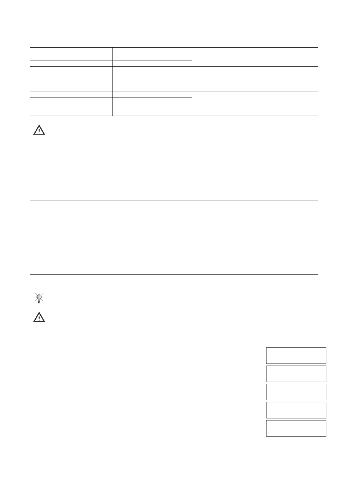
Available commands for the timing programmer are the following:
Command Description Notes and examples
Zones arm It activates the zone/zones
Zones disarm It deactivates the zone/zones
Commandable output activation It activates the commandable
output
Commandable output
deactivation
Key or user code enabling It enables a key or a code
Key or user code disabling It disables a key or a code
Warning: the timing programmer does not manage midweek holidays (Christmas, St. Stephen's day, New Year's
Day, Epiphany, Easter Monday, August holiday, etc.), that will be considered as the day of the week in which they
occur.
The time programming is always stored in the control panel and it is possible to enable or disable it, without deleting the
stored configurations, by following the procedures described in paragraphs 5.7.2 Timing programmer enabling and 5.7.3
Timing programmer disabling.
The time programming status (enabled or disabled) is displayed in the keypad by the timing programmer LED [7].
Commands performed by the timing programmer are active until the opposite command is given (by the programmer or
by a user with keypad or reader): in fact the programmer sends commands, but it does not check system or outputs
state.
Example of operation
An office is open from Monday to Friday, from 9 a.m. to 6 p.m. Days from Monday to Friday have been programmed as
working days, Saturday and Sunday as holidays. The first command set in the working day, at 8:55, is the burglar system
disarming and the last, at 18:05, the burglar system arming; during holidays there are no commands.
In practice, with enabled timing programmer, the system is automatically armed at the end of every working day and it is
disarmed in the morning of the following day. After arm on Saturday evening, it is not deactivated until Monday morning,
because on Saturday and Sunday there are no disarm commands.
If it is necessary to enter in protected premises, a user can manually disarm the system with the keypad or the reader
also on Saturday and Sunday. He must remember to arm again the system when he leaves the office, otherwise
premises will be without any protection.
4.18.2 Programming procedure
Suggestion: before starting programming procedure, fill in the specific tables (see paragraph 7.18 Timing
programmer): your work will become easier.
Warning: for timing programmer correct operation, control panel date and time must be correct (to change time
and date see paragraph 4.4 Time/date setting).
To program the timing programmer follow the instructions below:
1. Enter on the keypad the Installer code (default 000000) and press OK key.
2. Press MENU key.
3. Press ▼ key until “SETTINGS” appears on the display.
4. Press OK key to confirm.
5. Press ▼ key until “TIME PROGRAMMER” appears and confirm with OK key.
6. “DAY TYPE” appears; Press OK key to confirm.
7. “MONDAY” appears; Press again OK key.
8. Select with ▼ and ▲ keys the day type (working, pre-holiday and holiday ) to be assigned
to the displayed day of the week. Confirm the selection with OK key.
9. Go to the next day with▼ key.
10. Follow the same procedure from step 8. When every day of the week has the type
indication, go to step.
It deactivates the
commandable output
It is the remote-controlled output.
Domestic help or office cleaners: by combining the
two commands it is possible to allow the domestic
help to stay at home or cleaners in office, only in
given days and time.
UT00:INSTALLER
SETTINGS
SETTINGS
INCLUDE/EXCLUDE
SETTINGS
TIME PROGRAMMER
DAY TYPE
MONDAY
MONDAY
WORKING DAY
DS1067-035A 61 LBT8633
Page 62
11. Press ESC key to go to the upper level of the menu.
12. Press ▼ key; “COMMANDS TYPE” appears.
13. Press again OK key and select with ▼ and ▲ keys the day type (working, pre-holiday and
holiday ) to be configured.
14. Confirm the selection with OK key.
15. Press again OK key to select the command number, from 01 to 08.
16. Press OK key to confirm. Enter with keys the time for the planned programmer actions.
(midnight = 00:00) and confirm the entered time with OK.
17. Press ▼ key until “COMMAND TYPE” appears and confirm the selection with OK key.
18. Select among “NO ACTION”, “ARM” (ENABLE) and “DISARM” (DISABLE), and confirm
the selection with OK key. With “ARM” (ENABLE) and “DISARM” (DISABLE) it is also
necessary to select among “ZONES”, “OUTPUTS USERS”, “KEYS”, by using ▼ and ▲
keys and confirm with OK key.
19. According to the selection can appear:
USERS: Select with ▼ and ▲ keys the user to be enabled/disabled and confirm the selection
with OK key.
KEYS: Select with ▼ and ▲ keys the key to be enabled/disabled and confirm the selection
with OK key.
ZONES: Select the zones to be enabled/disabled with ◄ and ► keys and confirm the
selection with OK key. Valid zones are indicated by squares.
OUTPUTS: Confirm the selection with OK key (on the commandable output only).
20. Now it is possible to add other actions to the selected day type (follow the same
procedure from step 13 and select a new action) or program another day type (follow
the same procedure from step 8).
21. After programming the commands for the different day types, press ESC key repeatedly,
back to “COMMANDS TYPE”.
22. Press ▼ key; “WARNING TIME” appears
23. Press OK key. Select the warning time with ▼ and ▲ keys and confirm the selection with
OK key. Available values are No warning, 5, 10, 15 and 20 minutes. The warning time is
applied to all the commands of all the days of the week.
24. Press ESC repeatedly to exit from the menu.
4.18.3 Command deleting
To delete a command follow the procedure for programming; in operation selection choose “NO ACTION”. To stop all the
programming procedures it is not necessary to delete them, but it is sufficient to disable them (see paragraph 5.7.3
Timing programmer disabling).)
P.O.
COMMANDS TYPE
COMMANDS TYPE
WORKING DAY
WORKING DAY
COMMAND N:01
COMMAND N:01
COMMAND HOUR
COMMAND N:01
COMMANDS TYPE
COMMANDS TYPE
NO ACTION
USERS
Us02:...
KEYS
KE01:...
ZN01:...
□□□...
TIME PROGRAMMER
COMMANDS TYPE
TIME PROGRAMMER
WARNING TIME
WARNING TIME
NO WARNING
4.19 PROGRAMMING BY COMPUTER
All the configurations made by 1067/021 keypad can carried out, in an easier and friendly way, also with a PC and Urmet
FastPro 1067/001 software (release 2.10 or higher). All instructions for its use are described in the software manual. It is
necessary to enable the access by PC as follows: Master menu – Enable – Advanced – Enable remote access.
The control panel can be programmed by PC in the following ways:
• Local, by connecting the PC to the control panel via an USB port.
• Remote, by connecting the PC to the control panel via a modem and the telephone line; this connection allows also
system remote maintenance and management.
• Deferred, by storing the programming planned in laboratory on an USB key and then transfer it in the control panel.
DS1067-035A 62 LBT8633
Page 63

4.19.1 Technical prerequirements for data transfer
To connect the PC to the control panel or for data transfer only is needed:
Tipo di collegamento / trasferimento Required Material
Connection via USB port IT-USB Interface with USB cable. (Ref.1056/013 or Ref. 1067/003)
Connection via PSTN telephone line PSTN interface in control panel (Ref.1067/002)
Modem for teleservice and programming (Ref.1063/003)
Connection via GSM network GSM module in control panel (Ref.1067/458)
Modem for teleservice and programming (Ref.1063/003)
Connection via ADSL Ethernet interface (Ref. 1067/007)
ADSL Modem
PC side: Modem
Data download from USB key Interface for USB key - (Ref.1067/003)
USB key
4.19.2 Personal computer requirements
Personal computer minimum configuration:
• Pentium IV processor
• 256 MB Ram minimum
• 1,8 Ghz CPU
• 80 GB Hard Disk
• Windows 2000/XP Service Pack 2/Vista/ Windows7
• CD ROM reader
• Available serial port or USB port
4.19.3 Saving data to USB key and restoring data
By using the interface for USB key (Ref. 1067/003) it is for safety reasons possible to save carried out programming into
USB key. Instructions for connecting the interface in control panel 1067/032 e 1067/042 are in the Installation manual.
It is possible to separately save, in file form:
• programming and configuration for the whole system
• codes and keys
• event log
This data is saved into folder “1067” of USB key, and into subfolder having system code number as its name.
Folders, if not already present on the key, are automatically created by control panel.
All files have system number as their name and are differentiated as to their extension depending on their content.
E.g.: with control panel having system code 12345678, on USB there will be folder 1067:
12345678.cfg is the file which contains programming data, configuration data and control panel SW version
12345678.cod is the file which contains codes and keys
12345678.sto is the file which contains event log
4.19.3.1 Programming and configuration “.cfg” data Files
File 12345678.cfg can be read and edited on PC with software FastPro 1067/001 and can be recovered by control panel.
This function is useful, as an example, to restore the configuration of a control panel, copy its configuration into another
control panel or transfer, into a control panel, a configuration that was previously prepared at the laboratory.
4.19.3.2 Codes and keys “.cod” data Files
File 12345678.cod cannot be for safety reasons read by software FastPro 1067/001 and its content is encrypted.
It can only be recovered by control panel to be at any time able to restore previously saved codes and keys, or to copy
them from one control panel to another.
4.19.3.3 Event log “.sto” data Files
File 12345678.sto can be read on PC with software FastPro 1067/001.
This function is useful, as an example, to carry to and see on the PC the events that are stored by a control panel.
To save data to USB key and restore it, access item «MAINTENANCE» / «DATA TRANSFER»:
• «SAVE PROGR.» to save control panel data to USB key
o « CONFIGURATIONS »
o « KEYS CODES »
o « EVENT LOG »
• « RECOVER PROGR.» to copy data from to USB key to control panel
o « CONFIGURATIONS »
o « KEYS CODES »
To save and restore codes and keys Master User code has also to be entered.
DS1067-035A 63 LBT8633
Page 64
File saving and restoring operations can take some minutes; during these operations there appears on the display:
Warning: as long as USB/KEY interface yellow LED is on (Ref. 1067/003) USB key must not absolutely be
removed and control panel must not be powered off!
At the end, if the operation was completed correctly, “OK” confirmation appears; if it was not, “KO” appears.
WAIT PLEASE
4.20 SYSTEM TEST
When installation and configuration of system devices is finished, it is necessary to verify that the system is working
properly.
4.20.1 Inputs test
To verify if inputs are working properly follow the instructions below:
1. Enter on the keypad the Master code (default 111111) or the Installer code (default
000000) and press OK key.
2. Press MENU key.
3. Press ▼ key until “TEST” appears on the display.
4. Press OK key to confirm.
5. “INPUTS TEST IN PROGRESS...” appears. Press OK key to confirm.
6. Prompt all
the doors with magnetic contacts). Every time a detector is activated, on the keypad the
inputs LED turns on.
7. At the end press OK key to display the test result. Two different lists are available: the first
list, i.e. “TEST OK INPUTS”, signals all those inputs which were prompted during the test,
while the second list, i.e. “TEST KO INPUTS”, signals those inputs which were subjected to
variations. If all inputs opened regularly, no input must be present in the second list.
8. At the end press ESC key repeatedly to exit from the menu.
4.20.2 Outputs test
To verify if outputs are working properly follow the instructions below:
1. Enter on the keypad the Master code (default 111111) or the Installer code (default
000000) and press OK key.
2. Press MENU key.
3. Press ▼ key until “TEST” appears on the display.
4. Press OK key to confirm.
5. Press ▼ key until “TEST OUTPUT” appears.
6. Press OK key. “CONTROL PANEL” appears.
7. Confirm with OK key. The outputs list appears.
8. Select with ▲ and ▼ keys an output and press OK key. Press again OK to activate the
output; after verifying that the output is working properly, press OK key to deactivate it.
9. Follow the same procedure from step 7 for all the outputs.
10. If there are 1067/008 expansions, follow the same procedure from step 6 by selecting
every time a different bus device, whose outputs must be controlled.
11. After controlling all the outputs of all devices, press ESC key repeatedly to exit from the
menu.
system detectors (for example, walk in front of volumetric detectors and open
UT01:MASTER
TEST
TEST
TEST INPUTS
TEST INPUTS
IN PROGRESS...
TEST INPUTS
TEST RESULT
UT01:MASTER
TEST
TEST
TEST OUTPUTS
TEST OUTPUTS
CONTROL PANEL
CONTROL PANEL
UC.U1: U01
TEST OUTPUT
EXPANSIONS
DS1067-035A 64 LBT8633
Page 65
4.20.3 Battery test
To control the control panel battery state follow the instructions below:
1. Enter on the keypad the Master code or the Installer code and press OK key.
2. Press MENU key.
3. Press ▼ key until “TEST” appears on the display.
4. Press OK key to confirm.
5. Press ▼ key until “TEST BATTERY” appears on the display.
6. Press OK key to confirm.
7. “TEST BATTERY IN PROGRESS...” appears.
The battery test lasts for about 30 seconds, after which the system updates information about
the battery state indicated by the LEDs and in the event log (if there are changes).
8. At the end press ESC key repeatedly, to exit from the menu.
4.20.4 Vocal call test
To verify if vocal calls are working properly follow the instructions below:
1. Enter on the keypad the Master code or the Installer code and press OK key.
2. Press MENU key.
3. Press ▼ key until “TEST” appears on the display.
4. Press OK key to confirm.
5. Press ▼ key until “ADVANCED” appears on the display.
6. Press OK key. “VOCAL CALL” appears.
7. Confirm with OK key. Appears the list of the telephone numbers programmed as vocal
sending. NOTE: also appear telephone number digits.
8. Select with ▲ and ▼ keys the telephone number to which the test call must be sent
and press OK key. The communicator performs the call with the channel
programmed for the selected telephone number and sends the basic message for
three times.
9. Follow the same procedure from step 8 for all the telephone numbers to be tested.
10. Press ESC key repeatedly to exit from the menu.
4.20.5 Alarm reception centre call test
To verify if numerical calls are properly carried out, follow the instructions below:
1. Enter on the keypad the Master code or the Installer code and press OK key.
2. Press MENU key.
3. Press ▼ key until “TEST” appears on the display.
4. Press OK key to confirm.
5. Press ▼ key until “ADVANCED” appears on the display.
6. Press OK key. “VOCAL CALL” appears.
7. Press ▼ key until “PROTOCOL CALL” appears on the display. Confirm with OK key.
8. Appears the list of the telephone numbers programmed with numerical or modem sending.
9. Select with ▲ and ▼ keys the telephone number to which the test call must be sent and
press OK key. The communicator calls the Alarm reception centre and sends the test call
parameters for a correct identification of the event.
10. Follow the same procedure described in the previous step for all the numbers to be tested.
11. Press ESC key repeatedly to exit from the menu.
UT01:MASTER
TEST
TEST
TEST BATTERY
TEST BATTERY
IN PROGRESS...
UT01:MASTER
TEST
TEST
ADVANCED
ADVANCED
VOCAL CALL
VOCAL CALL
T01:xxxxxxxx
UT01:MASTER
TEST
TEST
ADVANCED
ADVANCED
VOCAL CALL
ADVANCED
PROTOCOL CALL
PROTOCOL CALL
T03:xxxxxxxxxx
DS1067-035A 65 LBT8633
Page 66
4.20.6 GSM field test
In order to check GSM signal level follow the instructions below:
1. Enter on the keypad the Master code or the Installer code and press OK key.
2. Press MENU key.
3. Press ▼ key until “TEST” appears on the display.
4. Press OK key to confirm.
5. Press ▼ key until “ADVANCED” appears on the display.
6. Press OK key.
7. Press ▼ key until “GSM FIELD TEST” appears on the display. Confirm with OK key.
8. Appears an indication of GSM signal level represented by dark squares.
9. Press ESC key repeatedly to exit from the menu.
Warning: In order to test the GSM must have enabled the function “GSM answer
machine” (see § 4.14.18).
4.20.7 Radio devices test
The flowchart below shows the flow of the tests that can be run on radio devices.
As concerns input device tests, no difference is made between wired devices and radio devices (see § 4.20.1).
All devices are grouped into two different menus which indicate the properly operating inputs with respect to the failing
ones: it will be up to the installer / maintenance operator to indicate radio devices with respect to wired devices by
means of proper name or via logic address.
Tests for output radio devices have been distinguished from the tests for wired devices by means of an appropriate
menu: after selecting the radio expansion, the command will arm or disarm the siren(s) connected.
Similarly to the basic concepts of the output device test, an appropriate advanced menu allows to monitor the signal
level reached by each device, in order to evaluate its operation and proper positioning with respect to the control panel.
In order to give simpler and friendly the interpretation of the diagram, the menu has been shown as effectively appear on
the keypad display. The navigation and confirm keys has been physically represented in order to guide the installer step
by step in the testing.
For further details regarding the keypad using, please refer to the paragraph 2.1 1067/021 Display Keypad.
NOTE: function available with 1067 control panel and 1067/021 keypads, software version 3.00 or higher a nd with an
1067/010 radio expansion.
UT01:MASTER
TEST
TEST
ADVANCED
ADVANCED
GSM FIELD TEST
GSM FIELD TEST
- +
DS1067-035A 66 LBT8633
Page 67
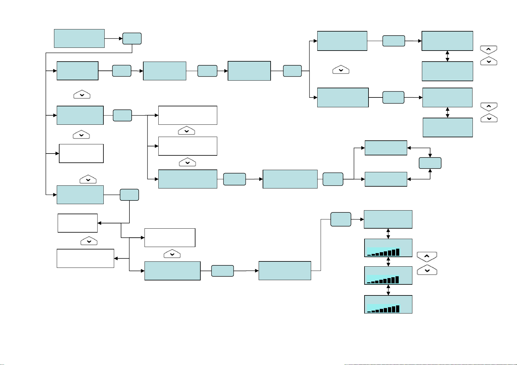
UT00:INSTALLER
TEST
TEST
TEST INPUTS
TEST
TEST OUTPUTS
TEST
BATTERY
TEST
ADVANCED
ADVANCED
VOCAL CALL
ADVANCED
GSM FIELD TEST
OK
OK
OK
OK
TEST INPUTS
IN PROGRESS
TEST OUTPUTS
CONTEOL PANEL
TEST OUTPUTS
EXPANSIONS
TEST OUTPUTS
RADIO DEVICES
ADVANCED
PROTOCOL CALL
ADVANCED
RADIO DEVICES
OK OK
TEST INPUTS
TEST RESULT
OK
OK
RADIO DEVICES
EW01:EW 01
RADIO DEVICES
EW01:EW 01
TEST RESULT
TEST INPUTS OK
TEST RESULT
TEST INPUTS KO
OK
OK
OK
OK
ER01:ER 01
ARM
ER01:ER 01
DISARM
TEST
IN PROGRESS:
IR01:…
RC04:…
DC03:…
TEST INPUTS OK
IN02:…..
TEST INPUTS OK
IN05:…..
TEST INPUTS KO
IN07:…
TEST INPUTS KO
IN09:…
OK
Page 68
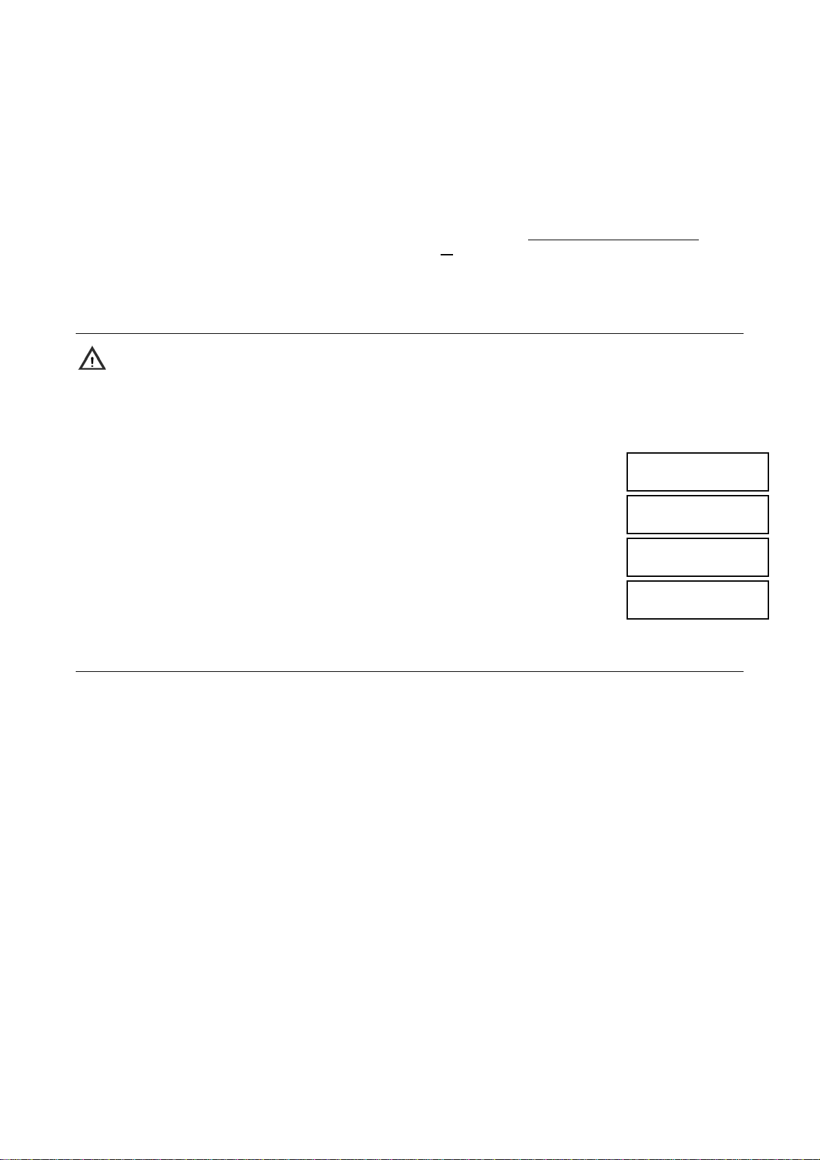
4.20.8 Environmental listening test
If in the system are included one or more keypads connected for environmental listening, it is strongly encouraged to
verify that this feature is working properly.
For this purpose make a call from a telephone located outside the area to be controlled and follow the procedure
described in paragraph 5.6.7 Environmental listening.
When the function is activated, verify that the signal level is good in all the area to be controlled; otherwise it should be
necessary to install further keypads in order to manage the zones where the signal is not sufficient.
4.20.9 Final tests
In addition to the above mentioned tests perform the following checks:
• System arming or disarming (total or partial) with keypads, if present, by using all the programmed user codes
• System arming or disarming with readers, if present, by using all
• System remote control - if the answer machine has been enabled - with fixed telephone, mobile or via modem (in
these cases it may be necessary the help of an external assistant).
the available keys.
.
4.21 EVENT LOG DELETING
Warning: deleting operation is not reversible!
At the end of installation, it is suggested to delete from the memory all the stored events, in order to deliver a “clean”
system.
To delete the event log follow the instructions below:
1. Enter on the keypad the Installer code (default 000000) and press OK key.
2. Press MENU key.
3. Press ▼ key until “EVENT LOG ” appears on the display.
4. Press OK key to confirm. “SYSTEM” appears on the display.
5. Press OK key to confirm and then ▼ key until “ERASE EVENT LOG” appears on the
display.
6. Press OK key. “ERASE EVENT LOG IN PROGRESS...” appears on the display and the
event log file is deleted.
7. Press ESC key repeatedly to exit from the menu.
UT00:INSTALLER
EVENT LOG
EVENT LOG
SYSTEM
SYSTEM
ERASE EVENT LOG
ERASE EVENT LOG
IN PROGRESS...
4.22 USERS TRAINING
Once the whole burglar system features have been verified, it is possible to show final users main operations to be
carried out on the system.
To obtain the best results from this training, follow the instructions below:
• If possible, directly involve all the people that will use 1067 system: if only one person is trained, he could forget
something or may not be able to pass on correct information to the other users.
• First carry out an operation yourself (for example, system arming or disarming) and then ask all people to repeat it in
your presence. So, if someone has doubts or any problem occurs, you will be able to help them.
• Invite people to ask any question: if all doubts are removed, users will be able to use easier the system.
Main instructions to be given to users concern:
• Complete system arm and disarm.
• Partial system arm and disarm.
• How to recognize different signalling: burglar, tamper attempt, flat battery, etc. (on display and acoustic).
• How to read the events stored in the control panel (Event log).
• How to change time and date, especially when time is changed from Solar Time to Summer Time and vice versa.
• How to enable remote management (if the control panel is equipped with the communicator).
• How to carry out the system periodical test.
Page 69
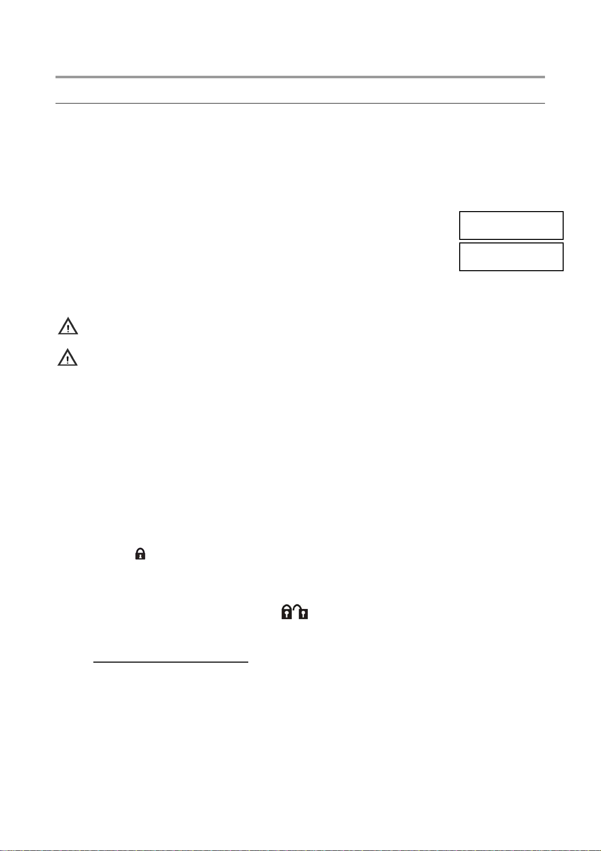
5 SYSTEM MANAGEMENT
5.1 ARMING
Two configurations are available: complete system arm and partial system arm.
Arm with keypad is the most configurable, while arms with electronic or proximity key are the easiest and the most
immediate.
If during arm there are open inputs, the system operates according to its configuration (Standard type zone,
Autoexclusion or System Arm lock).
5.1.1 Total arming with keypad
To totally arm the system follow the instructions below:
1. Enter on the keypad the Master code or a valid User code.
2. Press ON* key.
3. On the display appears an empty square for every existing and not active zone, associated to
keypad and code. Black squares, where present, indicate that the zone is already activated.
The buzzer signals that arm is in progress. To exit without arming press ESC key.
4. After 5 seconds the state LED turns on (steady if all the zones are activated, blinking if
some zones have not been activated) and the squares become black, indicating the
activated zones. If it is needed to speed up the procedure, press again ON* key and the
arm will be immediate.
5. The display automatically turns back to the standard screen after one minute. In order to
obtain in advance the standard screen, press ESC key.
Warning: , instead of the empty square, “O” appears, it means that at least one open input is present in that zone.
See, in detail, which is the input through menu item «OPEN INPUTS» and either close back or exclude that input.
Warning: by this procedure a user activates only the zones for which he is enabled, and not necessarily all the
zones.
5.1.2 Total arming with electronic or proximity key
To activate some zones with a reader, follow the instructions below:
1. Insert the electronic key in the reader, or bring near the proximity key to the proximity reader transponder
2. Remove the key or move the transponder away when the red LED “E” is blinking.
The 3 green LED indicate the status of the controlled zones: LED ON corresponds to zone armed.
If a LED has several assigned zones, this LED will blink if all these zones are not armed.
NOTE: The single zone arming capability depends on the key-reader settings and the utilized key.
From software release 2.00, several zones can be assigned to a each reader, up to covering all system zones (6 zones);
as a consequence several zones can be assigned to each green reader LED, up to covering the whole system.
5.1.3 Total arm by remote control
Total arm of all system zones can be only performed if the remote control has been properly programmed
(see § 4.11 Remote control programming).
To arm all zones (the whole system) via remote control, proceed as follows:
1. Press Key 1
buzzer will sound a beep.
2. On the keypad, the green LED “N “ corresponding to total arm will switch on.
3. On all readers, the green LEDs corresponding to all zones armed will switch on.
Note: the system can be armed /disarmed using Key 3
this key:
A. Pressing this key will switch system status from: disarmed to armed and vice versa (Toggle).
B. Should the system be armed partially (partial arm), pressing this key will align the system in “global arm”:
system not armed zones will be armed
C. Once having resumed the Total arming condition of all zones, pressing again key 3, will cause the Total
disarming of the system.
NOTE: function available with 1067 control panel a nd 1067/021 keypads, software version 3.00 or higher and w ith an
1067/010 radio expansion.
Arm remote control, if the control panel has acknowledged the command, the remote control
Toggle, however, take into account the operating mode of
.
ARM
□□□□..
EXECUTED
■■■■..
DS1067-035A 69 LBT8633
Page 70
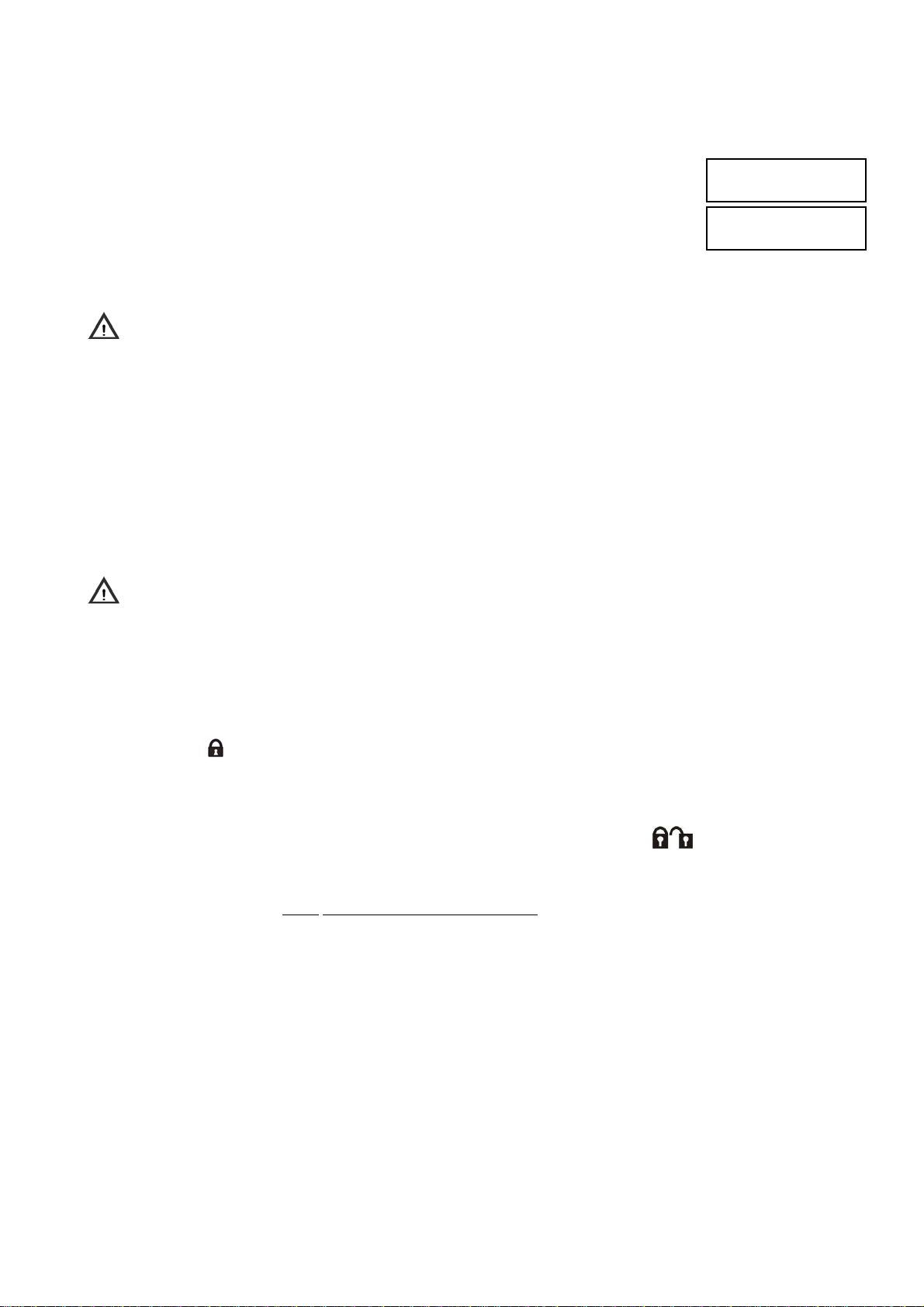
5.1.4 Partial arming with keypad
To partially arm the system, follow the instructions below:
1. Enter on the keypad the Master code or a valid User code.
2. Press ON* key.
3. On the display appears an empty square for each existing and not active zone, associated
to the keypad and to the code. Black squares, if present, indicate that the zone is already
activated. In order to exit without arming press ESC key.
4. While the keypad buzzer rings, enter on the keypad the number of zones to be activated:
the respective squares become black.
5. Press again ON* key; the state LED starts blinking and the selected zones are activated.
6. The display automatically turns back to the standard screen after one minute.
In order to obtain in advance the standard screen, press ESC key.
Warning: if, instead of the empty square, “O” appears, it means that at least one open input is present in that
zone. See, in detail, which is the input through menu item «OPEN INPUTS» and either close back or exclude
that input
5.1.5 Partial arming with electronic or proximity key
To partially arm the system, with electronic key, follow the instructions below:
1. Insert the electronic key in the reader; After a few seconds the reader will show the available partitioning sets
starting from the last performed one.
2. To confirm selection, take out the key: armed zone LEDs will stay on with fixed light.
To partially arm the system, with proximity key, follow the instructions below:
1. Approach the proximity key to the proximity reader transponder and keep it in this position for 3 seconds at
least.
2. Move it away when the green LEDs will start blinking.
After a few seconds the reader will show the available partitioning sets starting from the last performed one.
3. To confirm selection, approach the proximity key: armed zone LEDs will stay on with fixed light.
Warning: if yellow LED on the reader is blinking, it means that, in the system, at least one open input is present.
Before arming, identify the input and re-close or exclude it.
NOTE: If you use a key is not acquired (key not recognized), the green LEDs blink rapidly.
5.1.6 Partial arm by remote control
Partial arm of certain system zones can be only performed if the remote control has been properly programmed
(see § 4.11 Remote control programming).
To arm zones assigned to the remote control proceed as follows:
1. Press Key 1
buzzer will sound a beep.
2. On the keypad, the green LED “N “ will start blinking thereby confirming partial system arming.
3. On all reader, the green LEDs corresponding to armed zones will switch on.
Note: certain zones assigned to the remote control c an be armed / disarmed usin g Key 3
into account the operating mode of this key:
A. Pressing this key will switch system status from: disarmed to armed and vice versa (Toggle).
B. Should zones assigned to the remote control be partially armed (partia l arm), pressing this key will align all
zones to “arm” mode: zones
C. Once having set all zones assigned to the remote control in the arm condition, pressi ng again key 3, will cause
all zones disarming.
NOTE: function available with 1067 control panel a nd 1067/021 keypads, software version 3.00 or higher and w ith an
1067/010 radio expansion.
Arm remote control, if the control panel has acknowledged the command, the remote control
that were not armed will be armed.
ARM
□□□□...
EXECUTED
□■□□..
Toggle, however, take
DS1067-035A 70 LBT8633
Page 71
5.2 DISARMING
5.2.1 Total disarming with keypad
To totally disarm the system, follow the instructions below:
1. Enter on the keypad the Master code or a valid User code.
2. Press OFF# key.
3. On the display appears a black square for each existing and active zone, associated to the
keypad and to the code. Empty squares, if present, indicate that the zone is already
deactivated. The buzzer signals that disarm is in progress. To exit without disarming press
ESC key.
4. After 5 seconds the state LED turns off and the squares become white, indicating the
zones that have been disabled. If it is needed to speed up the procedure, press again
OFF* key and the disarm will be immediate.
5. The display automatically turns back to the standard screen after one minute.
In order to obtain in advance the standard screen, press ESC key.
Warning: by this procedure a user deactivates only the zones for which he is enabled, and not necessarily all the
zones.
5.2.2 Total disarming with electronic or proximity key
To disarm some zones with a reader, follow the instructions below:
1. Insert the electronic key in the reader, or bring near the proximity key to the transponder.
2. Take out the key or move the transponder away when the yellow LED will start blinking
3. The green LED will turn off.
4. Should any LED start blinking, this indicates that certain zones assigned to them are still armed, however they cannot
be disarmed by the key being used.
5.2.3 Total disarming by remote control
Total disarm of all system zones can be only performed if the remote control has been properly programmed
(see § 4.11 Remote control programming).
To disarm all zones (the whole system) via remote control, proceed as follows:
1. Press Key 4 Disarm, if the control panel has acknowledged the command, the remote control buzzer will sound
a beep.
2. On the keypad, the green LED “N “ will switch off thereby confirming total disarm.
3. On all readers, the green LEDs corresponding to all disarmed zones will switch off.
5.2.4 Partial disarming with keypad
To partially disarm the system, follow the instructions below:
1. Enter on the keypad the Master code or a valid User code.
2. Press OFF# key.
3. On the display appears a black square for each existing and active zone, associated to the
keypad and to the code. Empty squares, if present, indicate that the zone is already
deactivated. The buzzer signals that disarm is in progress. To exit without disarming press
ESC key.
4. Enter with the keypad the number of zones to be deactivated: the state LED blinks and the
respective squares become empty.
5. Press again OFF# key; the selected zones will be deactivated.
6. The display automatically turns back to the standard screen after one minute.
In order to obtain in advance the standard screen, press ESC key.
5.2.5 Hold-up disarming from keypad
When you are threatened and forced by a burglar, and risk your life, you can disarm the system from a keypad and at the
same time generate hold-up alarm, which, if programmed, can be via communicator sent as vocal, numeric message and
modem. Hol-up event cannot be detected locally in any way (no sirens, no optical warnings, etc.). To disarm system
under hold-up, just increment the last digit of your user code by one, then disarm. For example, if the user code is
000021, enter 000022.
DISARM
■■■■....
EXECUTED
□□□□....
DISARM
□■■□..
EXECUTED
□□■□..
DS1067-035A 71 LBT8633
Page 72
5.2.6 Stop of the active alarms
The modes to stop an alarm in progress are described in 3.1 Description of Alarms, Event s.
However, remember that:
• generally, outputs switched to an alarm event (sirens, etc.) go back to a rest condition when on the keypad a valid
code is entered;
• the cycle of vocal/SMS alarm calls can be interrupted by the telephone that received the call by entering “1 2” when
the message is finished and a beep is heard (it is necessary that the telephone uses the DTMF mode keypad, tone
mode); for emergency request vocal calls, block code “12” can be entered after closing environmental listening
session, at the end of the repetition of emergency request vocal message;
• vocal alarm calls cycle can be cancelled by entering a valid code on a keypad if the code is entered within 30
seconds from the start of the event and if call delay is enabled (see paragraph 4.14.21 Call time delay).
Vocal calls and SMS for burglar events can also be interrupted when the zones associated to the telephone numbers
programmed for the sending of these events are deactivated. This feature can be useful, for example in case of false
alarms. Consider that the call to the first available number can not be interrupted and continues, with that number, till the
end of attempts. However, no further calls to the next numbers will be carried out.
5.2.7 Wrong code entering
If a wrong access code is entered for 4 consecutive times, the control panel considers that event as a tamper attempt
and generates a tamper alarm, by activating all the configured alarm outputs and telephone calls, if present.
Once a correct code is entered, the wrong code counter is reset.
5.2.8 Masking on keypads and readers
The Masking is the function that allows anyone to not show the status of the system.
If the Masking function is active, the system status (active or not active) is not directly shown by the keypad LED and
display or with LED of electronic or transponder key readers. The Masking function is configured by the Installer during
the installation phase and can be set in a different way for every keypad or reader. However, the system status can be
controlled by entering a valid code on the keypad or by using a valid electronic or transponder key.
The acknowledgement of a valid key is warned about by reader 1
st
LED blinking; thereafter, system situation is shown
for about 10 seconds on the LEDs by the reader. Within this time, by approaching or putting in the key, arming, disarming
and partitioning normal operations are performed (see § 5.1 and 5.2).
5.3 FUNCTION KEYS WITH DIRECT ACCESS
The keypad has 3 keys pre-programmed for the following alarms:
• fire
• emergency
• silent panic
By pressing every key for 3 seconds at least, the control panel generates the respective event without entering any code.
Each single function key must be enabled in advance; see paragraph 4.8 Keypads programming.
5.3.1 1058/035 remote control direct access function key “+”
As described in paragraph 4.11 1058/035 remote c ontrol programming, key 2 “+” in addition to arm / disarm a specific
output (siren), also performs the direct access function, arming one of the following alarms:
Silent panic; Audible panic; Emergency; Fire alarm.
Pressing key “+” for 5 seconds at least, the radio expansion will communicate the alarm to the control panel, generating the
relevant event.
NOTE: function available with 1067 control panel a nd 1067/021 keypads, software version 3.00 or higher and w ith an
1067/010 radio expansion.
DS1067-035A 72 LBT8633
Page 73
5.4 DATE AND TIME CHANGING
Date and time stored in 1067/032 o 1067/042 control panel are used for the correct operation of the timing programmer
and to store events in the event log.
In order to change date and time shown on the display follow the procedure described in paragraph 4.4 TIME/DATE
SETTING.
5.5 EVENT LOG
The event log stores the last 1000 events (arms, disarms, alarms, tampers, etc.) concerning the system.
Events are stored from the most recent to the oldest one, so the most recent event has the lowest identification number.
When a new event is added, all the stored events are shifted down of one position.
When the event log reaches the maximum dimension (1000 events), every new event to be stored causes the oldest
stored event deleting. The event log can be examined both by the Master user and other users.
Warning: if the system has an areas configuration, the event log will be divided into equal parts among the
different users and every user can only read his own event data.
5.5.1 Read the Event log
To read the event log follow the instructions below:
1. Enter on the keypad the Master code (default 111111) and press OK key.
2. Press MENU key.
3. Press ▼ key until “EVENT LOG” appears on the display. Press OK key to confirm.
4. “SYSTEM” appears.
5. Press OK key to confirm.
6. Appear the 'list of the stored events', that is browsable with ▼ and ▲ keys. To understand
information on the display see paragraph 5.5.2 Meaning of event data.
7. After reading press ESC key repeatedly to exit from the menu.
5.5.2 Meaning of event data
In the event log an event is displayed as follows:
where
• xxxx is the event progressive number (0001 is the most recent event)
• hh:mm indicate event hour and minutes
• dd/MM indicate event day and month
• << Text >> is the event description
According to the event type are available further information that can be displayed in cyclic mode by pressing OK key
one or more time. For example: bus device and user/key.
5.5.3 Event log deleting
Warning: Event log deleting operation is not reversible!
To delete the Event log follow the instructions below:
1. Enter on the keypad the Installer code (default 000000) and press OK key.
2. Press MENU key.
3. Press ▼ key until “EVENT LOG” appears on the display. Press OK key to confirm.
4. “SYSTEM” appears.
5. Press OK key to confirm.
6. Press ▼ key until “ERASE EVENT LOG” appears on the display. Press OK key to confirm.
7. “ERASE EVENT LOG IN PROGRESS...” appears on the display and the event log is
deleted.
8. After deleting, press repeatedly ESC key to exit from the menu.
xxxx hh:mm dd/MM
<< Text >>
UT01:MASTER
EVENT LOG
EVENT LOG
SYSTEM
SYSTEM
READ EVENT LOG
0001 10:47 22/08
VALID CODE
UT01:INSTALLER
EVENT LOG
EVENT LOG
SYSTEM
SYSTEM
ERASE EVENT LOG
ERASE EVENT LOG
IN PROGRESS...
DS1067-035A 73 LBT8633
Page 74

5.6 USER REMOTE MANAGEMENT
5.6.1 Answering machine skip
In order to call 1067/032 or 1067/042 control panel for remote management, by using PSTN line, if on the line there are
an answering machine or a fax, the answering machine or the fax must answer after 2 rings at least. It is also necessary
to enable the control panel Answer machine function, by programming a number of rings higher than the answering
machine ring number.
It is possible to call 1067/032 or 1067/042 control panel for remote management by following the procedure described
below:
• Call the control panel and hang up after the first ring. The control panel detects the incoming call without answering,
because the number of rings is lower than the programmed number.
• Call again the control panel within 30 seconds.
• The control panel seizes immediately the line, after the first ring, without considering the programmed ring count. In
this way the answering machine or the fax will receive only one ring and they will not be able to seize the line instead
of the control panel.
This procedure is automatically carried out also by Remote control Centres with FastPro 1067/001 software and enabled
function.
5.6.2 Remote management with SMS messages
The outputs configured as “commandable” can be remote activated by sending SMS messages. To use this function
must be enabled the GSM answer machine and its GSM parameter “incoming SMS”. Besides, the SMS message must
come from a well known number, that is from one of the 12 stored telephone numbers (see § 4.14.2).
NOTE: it is not necessary that to the number are associated events to be sent.
The SMS sent to SIM telephone number of the control panel has the following syntax:
2nns.
where:
• nn is a number between 01 to 10 that identifies the commandable output or pulse commandable you want switch;
• s is a digit indicating the future output state: 1 (arm) or 0 (disarm).
• . (dot) is the terminator.
It is possible to queue more commands in the same SMS, separated by a comma. The SMS message must finish with a
dot (“.”).
Blanks, if present, will not be considered, but any characters different from numbers, blanks, commas and dots will be
considered as an error and SMS will be rejected.
Examples
SMS Description
2031. Correct: it activates the logical output 03
2 03 1. Correct: it activates the logical output 03
2031, 2050. Correct: it activates the logical output 03 and deactivates the logical output 05
To confirm that the command has been received, control panel sends an answer SMS headed by 3 exclamation marks
“!!!” followed by received message.
5.6.3 Request to send emails from Videoserver by SMS message
If Video Gateway is used (Ref. 1067/450) it is possible to request to send emails to email addresses defined on Video
Gateway by sending a specific request SMS to control panel.
To use this function, there have to be enabled GSM answer machine and GSM parameter “Incoming SMS”. Besides, the
SMS message must come from a well known number, that is from one of the 12 stored telephone numbers (see
§4.14.2).
Note: it is not necessary that to the number are associated events to be sent.
The SMS sent to SIM telephone number of the control panel has the following syntax:
8nn.
where:
• nn is the number – 01 to 04 – of the video camera from which images are to be received;
. (dot) is the terminator.
•
DS1067-035A 74 LBT8633
Page 75

5.6.4 Commandable outputs activation with no cost
This feature takes advantage of the Caller ID function of the calling telephone to carry out a fast activation of the
programmed commandable outputs.
The control panel must be provided with a GSM module with a valid SIM card, the network and the GSM answer
machine must be enabled.
To the commandable output associated are one or more numbers among the 12 stored telephone numbers.
A user with a known telephone number calls the control panel GSM number and must hang up within 3 rings.
All pulse commandable outputs associated to that number are activated and maintained activated for about one second
(a typical application is remote-controlled gate opener) and all switchable outputs associated to that number are
activated; to deactivate them, send relevant command via SMS.
To confirm that the command with no cost has been received, user receives, from control panel, a call having a duration
of some seconds; user must not answer to this call to prevent it from being charged to control panel SIM manager.
5.6.5 Remote management with vocal menu
The remote management call can be carried out both from a fixed telephone, provided with a DTMF keypad and from a
mobile. To take advantage of all the functions, also PSTN or GSM answer machine and remote disarm must be enabled
(Master menu – Enabling - Advanced).
With remote management it is possible:
• to arm zones (menu digit: 0)
• to disarm zones (menu digit: 1)
• to switch commandable outputs (menu digit: 2)
• to carry out environmental listening (menu digit: 3)
• to exclude/include inputs (menu digit: 4)
• request of system state summary (menu digit: 9)
The system state summary emits vocal messages concerning: active Zones, generic ev ents in Event lo g, Lack of power ,
Not functioning battery, SIM expiration. Even if present in memory, wrong code events or excluded inputs are not
managed.
In remote management “
To carry out the remote management, follow the instructions below:
1. Via a fixed or mobile phone, call control panel telephone number.
2. When it is requested, enter with the keypad a code (master or user) within 10 seconds; after each entered digit wait
for the confirmation beep before entering the next one. When all digits have been entered, enter “#”.If the code is
correct, a “Welcome” message will appear, otherwise try to enter again the code (up to a maximum of 3 attempts).
After identification, you have some seconds to enter the digit and directly access the desired menu, otherwise you will
be helped by a vocal menu: follow the instructions to access functions and use them.
3. To exit from remote management press repeatedly “*” key.
*” key (asterisk) allows to go back to the previous menu.
DS1067-035A 75 LBT8633
Page 76

5.6.6 Table with list of DTMF commands for vocal answer machine
Function Menu Accepted digits Operation Vocal messages
1÷6
followed by #
Zones arming 0
#
Arming of all selected zones
Arming of all configured zones
(total arm)
• List of zones indicated in
the command
• Arm result:
“ARMED EXECUTED”
or
“ARMED NOT EXECUTED”
1÷6
followed by #
Zones disarming 1
Commandable
outputs
Remote controls
Environmental
listening with
keypads
Inputs Exclusion
– Inclusion
System state
summary
5.6.7 Environmental listening
For environmental listening function must be present at least one keypad connected to the audio bus.
Remote environmental listening is activated by selecting “Environmental listening” menu item (number 3) and the number
of the keypad to be activated (from 1 to 8). Listening is active for about 1 minute and 30 seconds and automatically ends;
it is possible to interrupt the listening in advance with * key and turn back to the list of vocal commands.
2
3
(configured
keypads address)
4
List:
9
#
“01”-“10” Selection of the output driven
0 - 1
1 ÷ 8
“01”-“32”
1 Input exclusion
0 Input inclusion
Disarming of all selected zones
Disarming of all configured
zones (total disarm)
by remote control
Output command
(0 = deactivation; 1 = activation)
Activation
ENVIRONMENTAL LISTENING
on the selected keypad.
Selection of logical number of
the input to be
excluded/included (among
excludable inputs)
Zones Events State /
Stored Notices /
Present failures
• List of zones indicated in
the command
• Disarm result:
“DISARMED”
• Output present state
message
• Output command result
No messages
• Exclusion result
• Inclusion result
• Zones Messagges state
• Type events messages /
Stored notices
• Messages about present
failures
5.7 TIMING PROGRAMMER
5.7.1 Deferred automatic system arm
During the warning time (configured by the programming procedure) before the burglar system automatic arm with the
timing programmer, it is possible to defer for 30, 60 or 90 minutes the arm; this operation can be performed several
times, but within midnight.
Warning time is signalled by keypads with buzzers ringing and TIMING PROGRAMMER LEDs flashing; armed are also
“Insertion Warning” outputs.
To defer automatic arm its during this step necessary to:
• press MENU , «MOVE COMMAND» appears;
• press OK: Master code (predefined to 111111) OK;
• select, by keys ▲ and ▼, deferred time; and confirm with OK.
DS1067-035A 76 LBT8633
Page 77
5.7.2 Timing programmer enabling
To activate the timing programmer it is necessary to enable it.
Enabling is possible only if there are programmed timed commands.
To enable the timing programmer follow the instructions below:
1. Enter on the keypad the Master code (default 111111) and press OK key.
2. Press MENU key.
3. Press ▼ key until “ENABLE” appears on the display.
4. Press OK key to confirm.
5. Press ▼ key until “TIMED COMMANDS” appears and confirm with OK key.
6. Press ▼ key to select ENABLE and confirm with OK key.
7. Press ESC key repeatedly to exit from the menu.
If enabling is accepted, the green LED “clock” on the keypads will turn on.
5.7.3 Timing programmer disabling
The procedure to disable the timing programmer is similar to the enabling procedure, described in paragraph 5.7.2.
The only difference consists in selecting “DISABLE” at step 6.
By disabling the timing programmer any timed commands will be carried out. However timed commands are kept in
memory and will be active after the next Timing Programmer enabling.
UT01:MASTER
ENABLE
ENABLE
TIMED COMMANDS
TIMED COMMANDS
ENABLE
5.8 INPUTS EXCLUSION AND INCLUSION
In particular circumstances it may be necessary to temporarily exclude an input from the system, for example to carry out
a test or because the connected detector is damaged and signals a false alarm, preventing the system arm. The
exclusion of an input can reduce the safety provided by the system.
If the input is double balancing type, its exclusion prevents both alarm and tamper. However, its opening is signalled by
the lighting of the open inputs LED of associated keypads.
Warning: can be excluded only inputs with EXCLUDABLE parameter, enabled with the programming procedure.
5.8.1 Input exclusion
To exclude an input follow the instructions below:
1. Enter on the keypad a user code or the Master code and press OK key.
2. Press MENU key.
3. Press ▼ key until “SETTINGS” appears on the display.
4. Press OK key to confirm. “INCLUDE/EXCLUDE” appears.
5. Press OK key. Appears the list of inputs that can be excluded.
6. Select with ▲ and ▼ keys the input to be excluded and confirm the selection with OK key.
7. Confirm with OK key.
Exclusion message will appear and also “excluded inputs” LEDs on the keypads will turn on.
8. Press ESC key repeatedly to exit from the menu.
UT01:MASTER
SETTINGS
SETTINGS
INCLUDE/EXCLUDE
INCLUDE/EXCLUDE
IN01:...
IN01:...
EXCLUDE OK?
EXCLUDE
IN01:...
DS1067-035A 77 LBT8633
Page 78
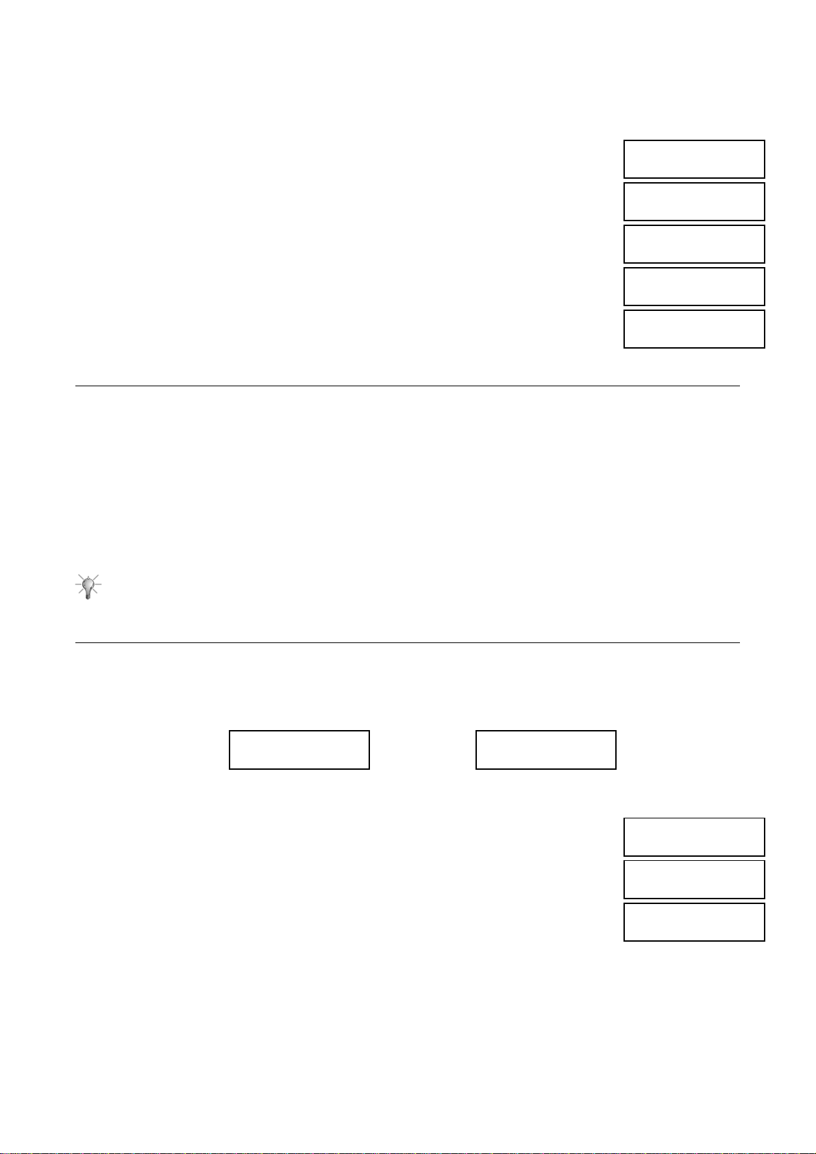
5.8.2 Input inclusion
To include again an input follow the instructions below:
1. Enter on the keypad a user code or the Master code (default 111111) and press OK key.
2. Press MENU key.
3. Press ▼ key until “SETTINGS” appears on the display.
4. Press OK key to confirm. “INCLUDE/EXCLUDE” appears.
5. Press OK key. Appears the list of inputs that can be included.
6. Select with ▲ and ▼ keys the input to be included and confirm the selection with OK key.
7. Confirm with OK key. The input has been included in the system again.
8. Press ESC key repeatedly to exit from the menu.
UT01:MASTER
SETTINGS
SETTINGS
INCLUDE/EXCLUDE
INCLUDE/EXCLUDE
IN01:...
IN01:...
INCLUDE OK?
EXCLUDE
IN01:...
5.9 PERIODIC TESTS
È buona pratica verificare periodicamente il corretto funzionamento del sistema antintrusione.
I principali test da effettuare sono:
• Inputs test
• Outputs test
• Battery test Control panel
• Vocal call test
• Remote control call test (if present)
• GSM test (if present)
• Radio devices test
Refer to the procedures described in paragraph 4.20 System test to check the correct working of each element of the
system.
Suggestion: carry out a test of 1067 system before long absences, for example before the summer holidays.
5.10 VARIOUS
Every 1067/021 keypad has some parameters that can be locally customized, as described below.
5.10.1 Display Info
In stand-by condition, the keypad display can show date and time or the system zones status. For each system keypad it
is possible to select the displaying mode.
To change the stand-by screen of the keypad display follow the instructions below:
1. On the keypad press MENU key.
2. Press ▼ key until “LCD INFO” appears on the display.
3. Press OK key to confirm.
4. Enter a valid User code or the Master or Installer code and press OK.
5. With ▼ and ▲ keys select between DATE / HOUR and SYNOPTIC (for zones status) and
confirm the selection with OK key.
6. Press ESC key repeatedly to exit from the menu.
yy/mm/yyyy hh:mm
URMET
SYSTEM STATUS
□□■□..
SYSTEM STATUS
LCD INFO
ENTER CODE
LCD INFO
DATE / HOUR
DS1067-035A 78 LBT8633
Page 79
5.10.2 Buzzer volume adjustment
It is possible to change the buzzer volume of every single keypad. For buzzer volume adjustment no user codes are
needed.
To change the buzzer volume follow the instructions below:
1. On the concerned keypad press MENU key.
2. Press ▼ key until “SET BUZZER” appears on the display.
3. Press OK key to confirm.
4. Press ◄ and ► keys for adjustment; every time a key is pressed, the buzzer will emit a
sound at the corresponding volume. Confirm the new volume by pressing OK key.
5. Press ESC key repeatedly to exit from the menu.
It is possible to modify the display contrast of every single keypad, in order to optimize it for the viewing angle relatively
to the physical position of the keypad.
For contrast adjustment no user codes are needed.
To modify display contrast follow the instructions below:
1. On the concerned keypad press MENU key.
2. Press ▼ key until “SET CONTRAST” appears on the display.
3. Press OK key to confirm.
4. Press ◄ and ► keys to adjust the contrast. Confirm the new display contrast by pressing
5. Press ESC key repeatedly to exit from the menu.
It is possible to change the brightness of display, keys and LEDs of every single keypad.
For brightness adjustment no user codes are needed.
To change the keypad backlight brightness follow the instructions below:
1. On the concerned keypad press MENU key.
2. Press ▼ key until “SET BACKLIGHT” appears on the display.
3. Press OK key to confirm
4. Press ◄ and ► keys to adjust the brightness. Confirm the new brightness by pressing OK
5. Press ESC key repeatedly to exit from the menu.
Warning: if the volume level is decreased to 0 (no squares on) the buzzer will not signal any more the entryexit time, gong and keys pressing.
5.10.3 Display contrast adjustment
OK key.
5.10.4 Back-lighting adjustment of keypad and display
key.
Warning: if the level is decreased to 0 (no squares on), back-light will be totally turned off.
Warning: Backlight adjustment also affects status LEDs intensity (but they are not turned off by setting level 0);
this adjustment affects keypad current consumption.
SYSTEM STATUS
SET BUZZER
SET BUZZER
- +
SYSTEM STATUS
SET CONTRAST
SET CONTRAST
- +
SYSTEM STATUS
SET BACKLIGHT
SET BACKLIGHT
- +
5.11 MAINTENANCE
In Maintenance menu are available some commands used for system “physical” management; for the complete
maintenance procedure see Installation manual.
Some of them do not require any physical operations and are described below.
5.11.1 Language change
This procedure was described before in paragraph 4.3 Language selection.
DS1067-035A 79 LBT8633
Page 80
5.11.2 Device address display
To verify the address of a specific system bus device follow the instructions below:
1. Enter on the keypad the Installer code and press OK key.
2. Press MENU key.
3. Press ▼ key until “MAINTENANCE” appears on the display.
4. Press OK key to confirm.
5. Press ▼ key until “SHOW ADDRESSES” appears.
6. Press OK key to confirm.
7. Select with ▲ and ▼ keys the device to be examined: EXPANSIONS, KEYPADS,
READERS or RADIO DEVICES. Confirm the selection with OK key.
8. Appears the address list of this device type, browse it with ▼ and ▲ keys.
9. Select the desired device and confirm with OK key.
10. “IN PROGRESS…” appears.
Consider all the installed devices: the device with the desired address will have the
acquisition yellow LED blinking. Press the acquisition key on the selected device to confirm
that the search has been successful and turn off the LED.
11. On the keypad where the installation started press ESC key repeatedly to exit from the menu.
5.11.3 Software release display
To know the software version in a bus device of the system (or of the control panel) follow the
instructions below:
1. Enter on the keypad the Installer code and press OK key.
2. Press MENU key.
3. Press ▼ key until “MAINTENANCE” appears on the display.
4. Press OK key to confirm.
5. Press ▼ key until “SW. REL” appears.
6. Press OK key to confirm.
7. Select with ▲ and ▼ keys the device to be examined: CONTROL PANEL, EXPANSIONS,
KEYPADS, READERS or RADIO DEVICES. Confirm the selection with OK key.
8. If CONTROL PANEL has been selected, it is possible to directly read the software version.
In the other cases it is necessary to select the desired device from a list (with▼, ▲ and OK
keys) before reading the software version.
9. Press ESC key repeatedly to exit from the menu.
5.11.4 Partial reset
With partial reset, all configurations of the system device, included control panel configurations, are
reset to factory settings. Codes, keys and event log are not deleted. To partially reset follow the
instructions below:
1. Enter on the keypad the Installer code and press OK key.
2. Press MENU key.
3. Press ▼ key until “MAINTENANCE” appears on the display.
4. Press OK key to confirm.
5. Press ▼ key until “PARTIAL RESET” appears and press OK key to confirm.
6. Press OK key to confirm or ESC key to undo the operation.
7. “IN PROGRESS...” appears on the display and the buzzer rings.
8. At the end of operation “MAINTENANCE” “PARTIAL RESET” appears again.
Now it is possible to program the system again.
UT00:INSTALLER
MAINTENANCE
MAINTENANCE
SHOW ADDRESSES
SHOW ADDRESSES
EXPANSIONS
EXPANSIONS
EPxx:EPxx
Epxx:EPxx
IN PROGRESS...
UT00:INSTALLER
MAINTENANCE
MAINTENANCE
SW. REL
SW. REL
CONTROL PANEL
CONTROL PANEL
REL. xx.xx
UT00:INSTALLER
MAINTENANCE
MAINTENANCE
PARTIAL RESET
PARTIAL RESET
ARE YOU SURE?
PARTIAL RESET
IN PROGRESS...
DS1067-035A 80 LBT8633
Page 81

5.11.5 Global reset
With global reset, all control panel configurations are reset to factory settings (inputs, outputs, zones, timing programmer,
PSTN/GSM telephone parameters) and all previously acquired devices are removed, by replacing respective
configurations with factory settings and deleting the address.
To totally reset follow the instructions below:
1. Enter on the keypad the Installer code (default 000000) and press OK key.
2. Press MENU key.
3. Press ▼ key until “MAINTENANCE” appears on the display.
4. Press OK key to confirm.
5. Press ▼ key until “GLOBAL RESET” appears and press OK key to confirm.
6. Press OK key to confirm or ESC key to undo the operation.
7. “IN PROGRESS...” appears on the display and the buzzer rings.
8. At the end of operation, on keypads appears a row of dots. Turn the system off and start
again from chapter 4 Start-up in the Installation manual.
5.11.6 Backup-Restore
This procedure is already described in paragraph 4.19 Programming by computer.
UT00:INSTALLER
MAINTENANCE
MAINTENANCE
GLOBAL RESET
GLOBAL RESET
ARE YOU SURE?
GLOBAL RESET
IN PROGRESS...
DS1067-035A 81 LBT8633
Page 82
6 MENU
p
p
y
p
y
p
p
r
p
g
6.1 MASTER MENU
Start selections in Master menu are:
SYSTEM STATUS
EVENT LOG
SETTINGS
ENABLE
TEST
TELEPHONE DIALER
It shows system status and allows to modify zone status.
It allows to read the list of the events stored in the control
(see § 5.1.1 Event log submenu).
It allows to exclude in
reset their codes to factor
trans
onder; configure timing programmer (see § 5.1.2 Setting submenu).
It allows to enable and disable Installer, Users, Ke
disarming froma a remote location (see § 5.1.3 Enabling submenu).
It allows to
There can be se
devices connected to the bus, the battery and vocal telephone calls as well as the calls to
remote su
It allows to program or change phone numbers, to record the basic vocal message, to create
and delete SMS messa
erform specific tests to check for system perfect operation.
ervision centres and GSM signal (see § 5.1.4 Test submenu).
uts, set current time and date, change Master code, configure user or
values, acquire configure and delete electronic keys and
arately checked the inputs and outputs of control panel and of the othe
es (see § 5.1.5 Telephone dialer submenu).
anel memory.
s, timing programmer, access and
Depending on choice made, other menu tree items can be accessed, as shown below.
With system active, only item System status can be accessed (see § 2.4.1).
6.1.1 Event log submenu
LEVEL 2 LEVEL 3 LEVEL 4 LEVEL 5
READ EVENT LOG
DS1067-035A 82 LBT8633
Page 83
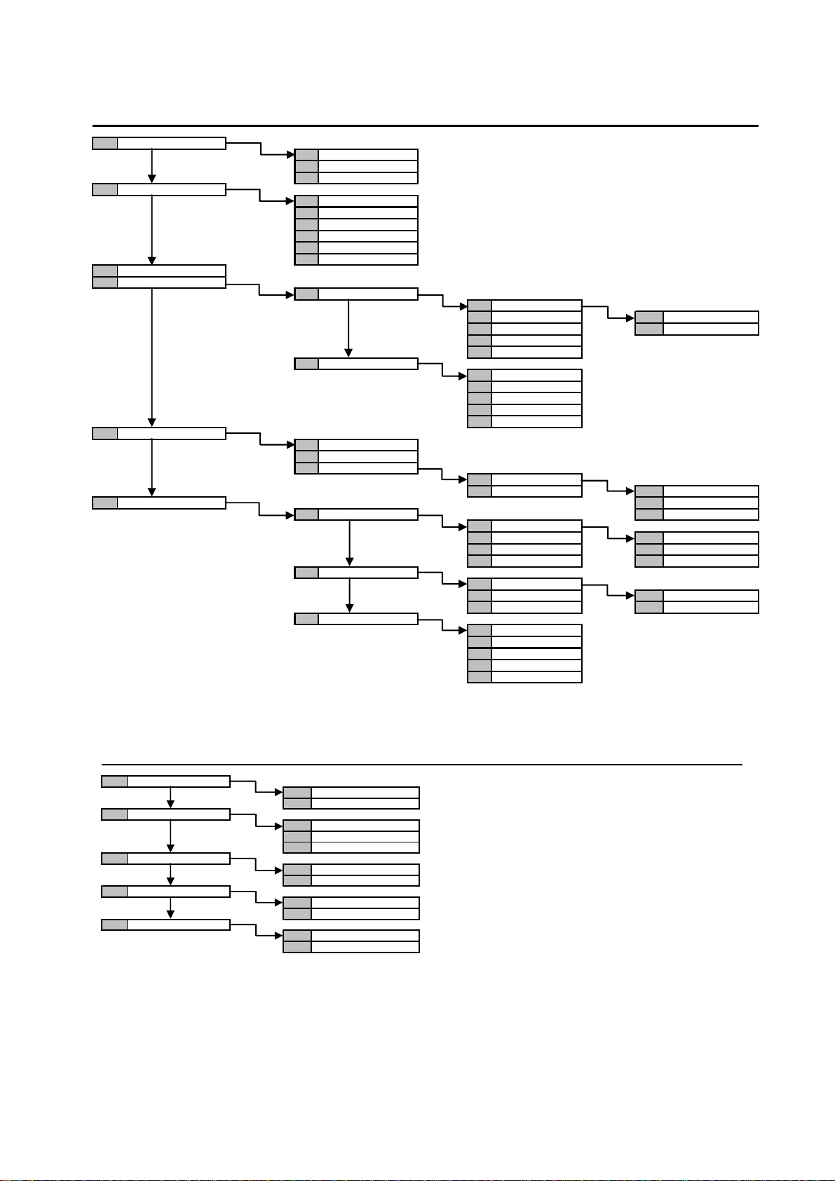
6.1.2 Settings submenu
LEVEL 2 LEVEL 3 LEVEL 4 LEVEL 5
EXCLUDE / INCLUDE
IN01:...
IN02:...
...
HOUR-DATE
SET HOUR
SET DATE
SUMMER TIME
LEGAL T.MONTH
SUMMER T.MONTH
SUNDAY
CHANGE CODE
USERS
CONFIGURE USERS
UT00: INSTALLER
UT01: MASTER ASSIGN
UT02:... NAME
…
UT31:...
DEFAULT CODE
UT00: INSTALLER
UT01: MASTER
UT02:...
…
UT31:...
KEYS
ACQUIRE KEY
DELETE KEY
CONFIG. KEY
KE01:...
...
P.O. (TIMING PROGR.) ASSIGN
DAY TYPE NAME
MONDAY
TUESDAY WORKING DAY
... PRE-HOLIDAY
SUNDAY HOLIDAY
COMMANDS TYPE
WORKING DAY
HOLIDAY COMMAND N:01
PRE-HOLIDAY ...
WARNING TIME
NO WARNING
WARNING 5 min
WARNING 10 min
WARNING 15 min
WARNING 20 min
FUNCTION KEY
6.1.3 Enabling submenu
LIVELLO 2 LEVEL 3 LEVEL 4 LEVEL 5
INSTALLER
USER
KEY
TIMED COMMANDS
ADVANCED
DISABLE
ENABLE
UT02:...
…
UT31:...
KE01:...
...
DISABLE
ENABLE
REMOTE ACCESS
REMOTE DISARMED
DS1067-035A 83 LBT8633
Page 84
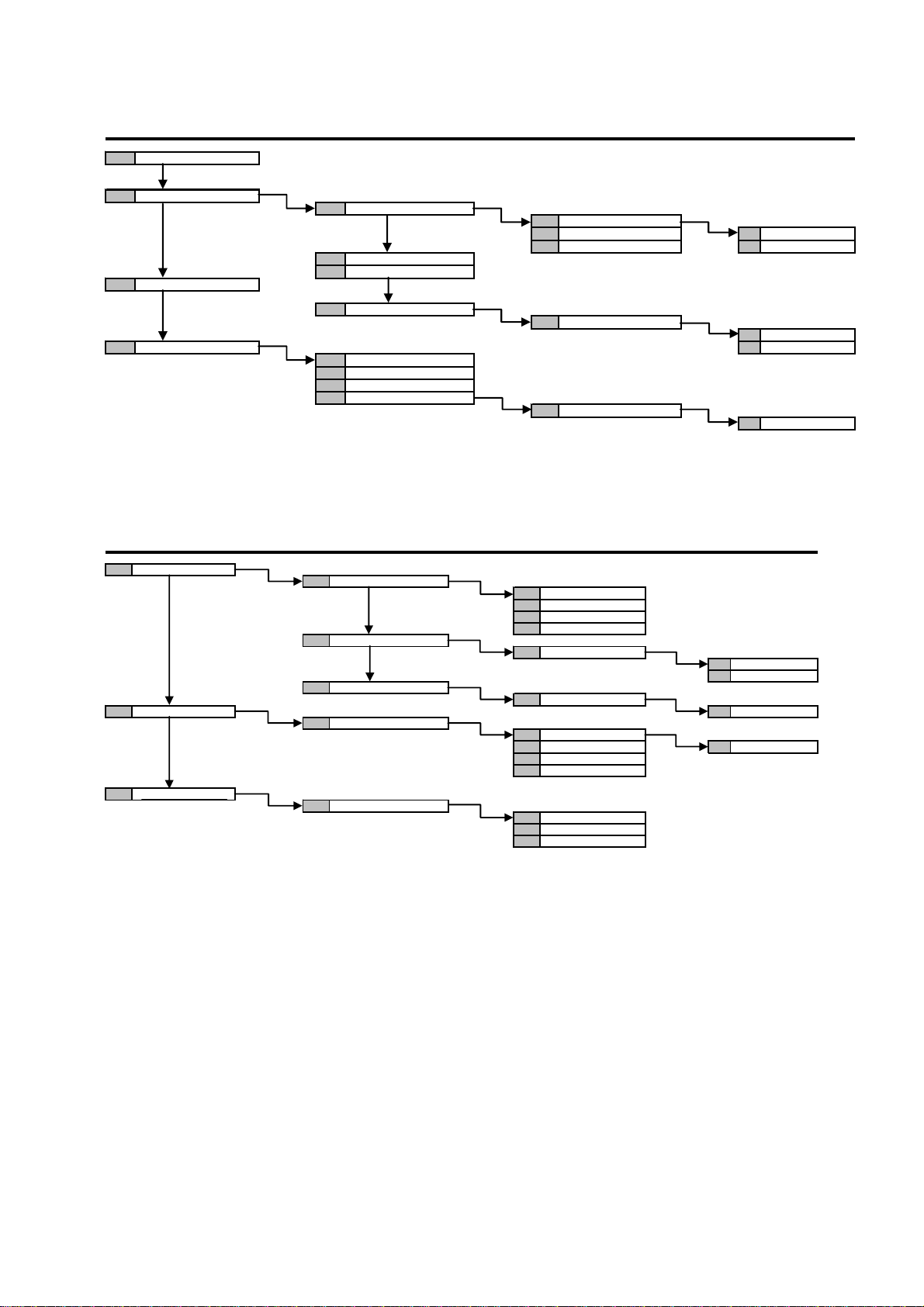
6.1.4 Test submenu
LEVEL 2 LEVEL 3 LEVEL 4 LEVEL 5
TEST INPUTS
TEST OUTPUTS
TEST BATTERY
ADVANCED DEACTIVATE
6.1.5 Telephone dialer submenu
LEVEL 2 LEVEL 3 LEVEL 4 LEVEL 5
PHONE NUMBERS
VOCAL MESSAGES SELECT LINE
SMS MESSAGES
CONTROL PANEL
EXPANSIONS
...
RADIO DEVICES
VOCAL CALL
PROTOCOL CALL
GSM FIELD TEST
RADIO DEVICES
TEL.NUMBER
ASSIGN TEL. N.
PHONE LINE
MESSAGGES LIST
WRITE SMS
UC.U1: U01
UC.U2: U02 ACTIVATE
… DEACTIVATE
EW01:EW 01
EW01:EW 01
T01:
T02:
...
T12:
T01:
T01:
BASE MESSAGE
BURGLAR PLAY
TECHNOL. TYPE 1
...
BURGLAR
TECHNOL. TYPE 1
...
SYSTEM
ZONES
ACTIVATE
IN PROGRESS
DS1067-035A 84 LBT8633
Page 85
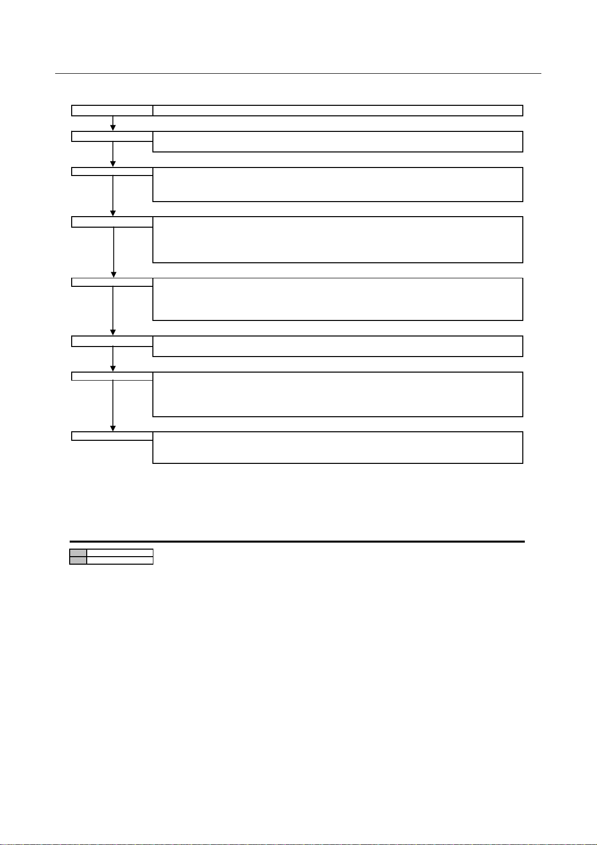
6.2 INSTALLER MENU
Start selections in Installer menu are:
SYSTEM STATUS
It allows to verify the status of the zones and modify them.
EVENT LOG
SETTINGS
TEST
PROGRAMMING
PARAMETERS
TELEPHONE DIALER
It allows to read and delete the list of events stored in the control panel.
(see § 6.2.1 Eventt log submenu ).
It allows to exclude inputs, set time and date, change installer code, configure users or reset their codes to
default values, acquire configure or delete electonic keys and transponders; to configure timing programmer
(see § 6.2.2 Setting submenu).
It allows to carry out specific tests to check the system correct working.
There can be separately checked the inputs and outputs of control panel and of the other devices connected
to the bus, the battery and vocal telephone calls as well as the calls to remote supervision centres and GSM
signal (see § 6.2.3 Test submenu ).
It allows to set the number of system zones and configure them, to configure the inputs of control panel and
of the other bus peripheral units, to configure the outputs of control panel and expansions, to configure
keypads and readers and program system code for remote management (see § 5.2.4 System programming
submenu).
It allows to set system general timing.
(see § 6.2.5 Parameters Submenu).
It allows to program or modify telephone numbers for sending alarms and warnings, associate specific alarms
to every telephone number and specify sending modes, set parameters for PSTN and GSM networks, edit
SMS messages, enable and configure other telephone functions (see § 6.2.6 Telephone dialer Submenu).
MAINTENANCE
It allows to perform maintenance operations on the system, as well as change of language, acquiring new
devices, removing devices, resetting and saving programming operations carried out (see § 6.2.7
Maintenance Submenu).
With system active, only item System status can be accessed (see § 2.4.1).
6.2.1 Event log submenu
LEVEL 2 LEVEL 3 LEVEL 4 LEVEL 5
READ EVENT LOG
ERASE EVENT LOG
DS1067-035A 85 LBT8633
Page 86
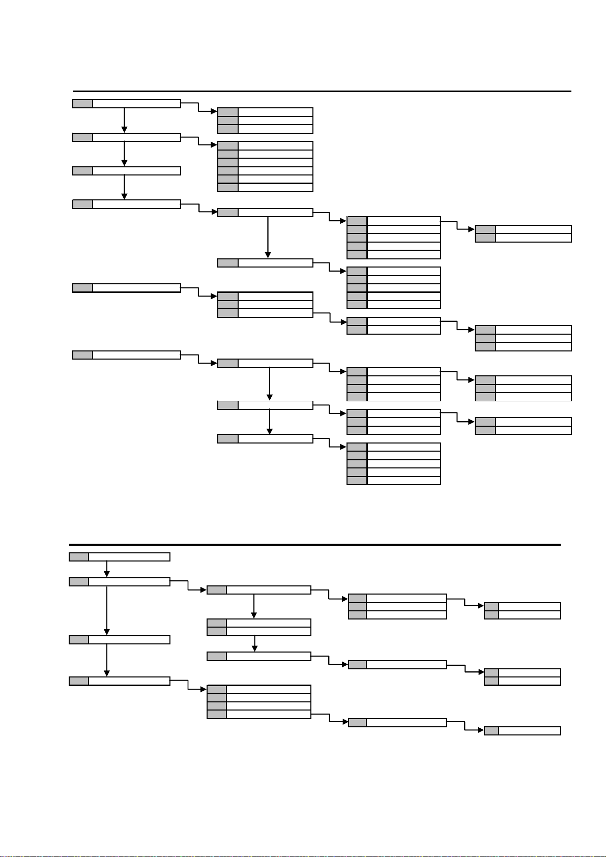
6.2.2 Settings submenu
LEVEL 2 LEVEL 3 LEVEL 4 LEVEL 5
EXCLUDE / INCLUDE
HOUR-DATE
CHANGE CODE LEGAL T.MONTH
USERS
KEYS UT02:...
P.O. (TIMING PROGR.)
IN01:...
IN02:...
…
SET HOUR
SET DATE
SUMMER TIME
SUMMER T.MONTH
SUNDAY
CONFIGURE USERS
UT00:INSTALLER
UT01: MASTER ASSIGN
UT02:... NAME
…
UT31:...
DEFAULT CODE
UT00:INSTALLER
UT01: MASTER
ACQUIRE KEY …
DELETE KEY UT31:...
CONFIG. KEY
KE01:...
… KEY FUNCTION
ASSIGN
NAME
DAY TYPE
MONDAY
TUESDAY WORKING DAY
… PRE-HOLIDAY
SUNDAY HOLIDAY
COMMANDS TYPE
WORKING DAY
HOLIDAY COMMAND N:01
PRE-HOLIDAY ...
WARNING TIME
NO WARNING
WARNING 5 min
WARNING 10 min
WARNING 15 min
WARNING 20 min
6.2.3 Test submenu
LEVEL 2 LEVEL 3 LEVEL 4 LEVEL 5
TEST INPUTS
TEST OUTPUTS
TEST BATTERY
ADVANCED DEACTIVATE
CONTROL PANEL
UC.U1: U01
UC.U2: U02 ACTIVATE
… DEACTIVATE
EXPANSIONS
...
RADIO DEVICES
EW01:EW 01
ACTIVATE
VOCAL CALL
PROTOCOL CALL
GSM FIELD TEST
RADIO DEVICES
EW01:EW 01
IN PROGRESS
DS1067-035A 86 LBT8633
Page 87
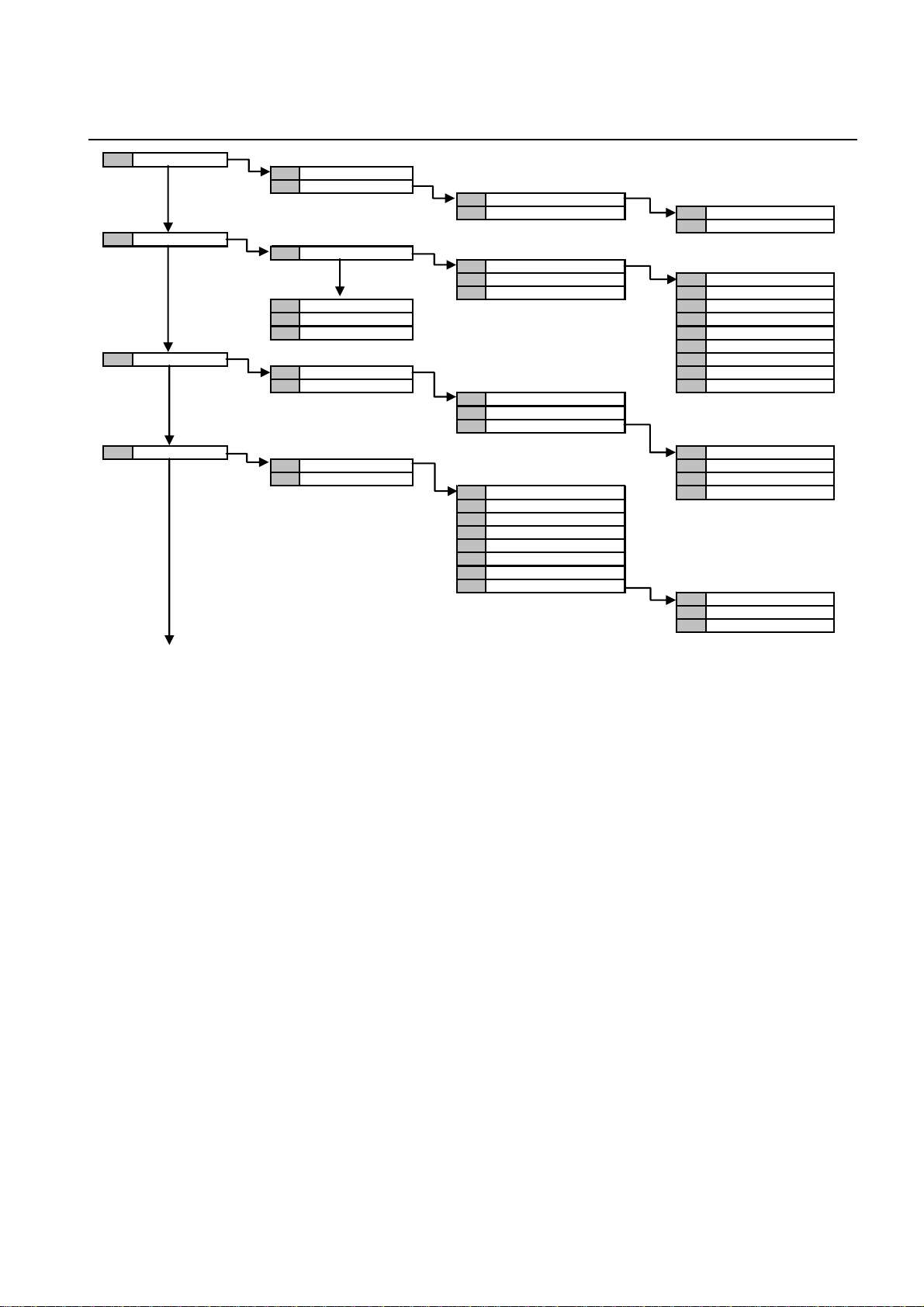
6.2.4 System programming submenu
LEVEL 2 LEVEL 3 LEVEL 4 LEVEL 5
ZONES
INPUTS
OUTPUTS VIDEO ASSIGN
KEYS OUTPUT TYPE
ZONES NO:
CONFIG.ZONES
ZN01:...
… ACTIVATION MODE
NAME
CONTROL PANEL
UC.In1: In01
UC.In2: In02 INPUT TYPE
… ASSIGN
EXPANSIONS CUSTOMIZE
KEYS BYPASS ALLOWED
READERS ANCILLARY FUNCT.
ATTRIBUTES
CONTROL PANEL AND INPUTS
EXPANSIONS NAME
UC.U1: U01
UC.U2: U02
…
KP01:KP 01 ASSIGN
… CUSTOMIZE
ASSIGN NAME
GONG FUNCTION
SOUND TIME ENTRY
SOUND TIME EXIT
ENVIR. LISTENING
MASKING
NAME
KEYS FUNCTION
FIRE ALARM
SILENT PANIC
EMERGENCY
DS1067-035A 87 LBT8633
Page 88
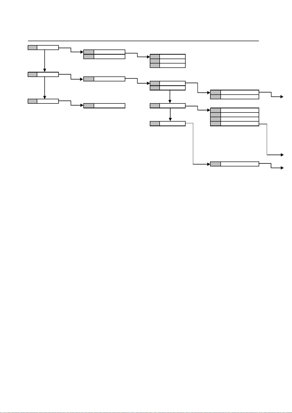
LEVEL 2 LEVEL 3 LEVEL 4 LEVEL 5
READERS
RADIO DEV.
ADVANCED
LT01:LT 01
... ASSIGN
MASKING
NAME
EW01:EW 01
SELECT IR
SELECT DC
SYSTEM CODE SIRENS
SELECT RC
IR01. In1: In01
…
ASSIGN
CUSTOMIZE
STATUS REPORT
SELECT SIREN
SELEC RC
DS1067-035A 88 LBT8633
Page 89
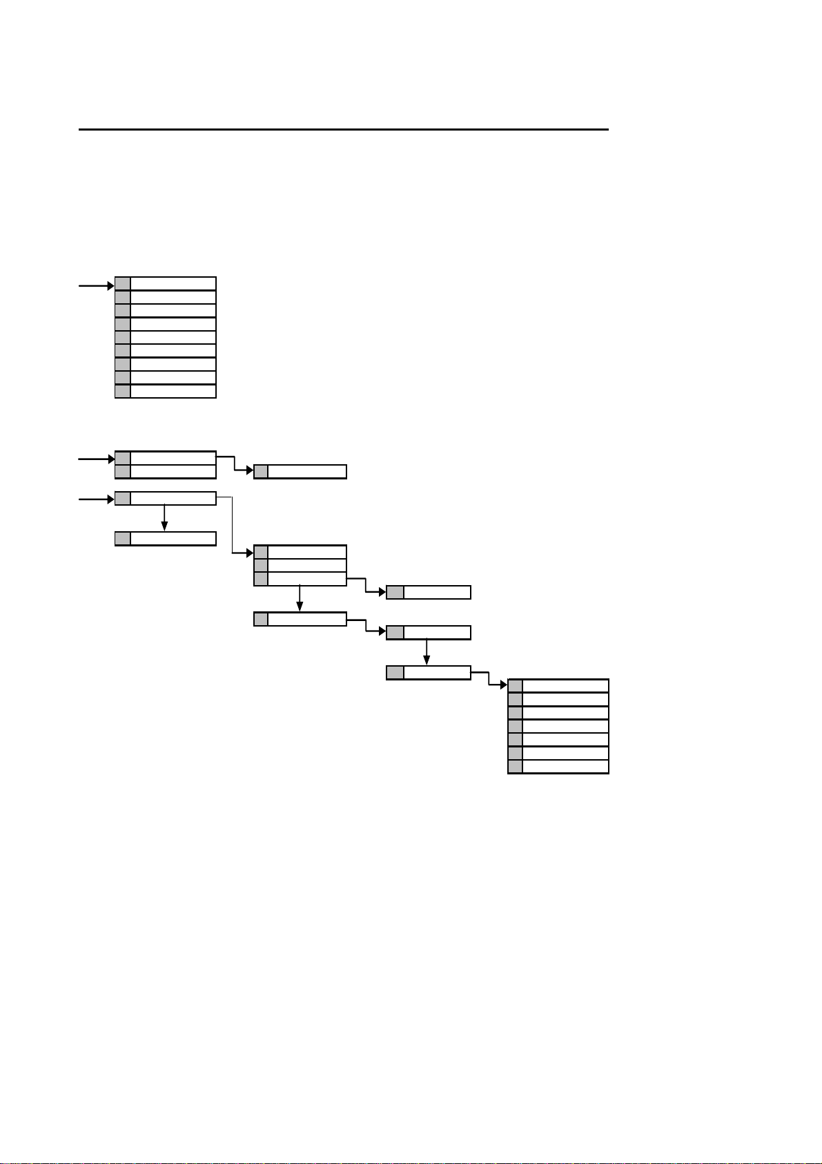
LEVEL 6 LEVEL 7 LEVEL 8 LEVEL 9
INPUT TYPE
ASSIGN
CUSTOMIZE
BYPASS ALLOWED
ANCILLARY FUNCT.
ATTRIBUTES
VIDEO ASSIGN
AND INPUTS
NAME
HP01.U-: U07
…NAME
PROG. TASTI
NAME
1 ARM
3 TOGGLE
4 DISARM
ASSIGN
2 GENERIC
ASSIGN
COMMAND TYPE
NOT USED
DISARM (DISABLE)
ARM (ENABLE)
FIRE ALARM
SILENT PANIC
AUDIBLE PANIC
EMERGENCY
DS1067-035A 89 LBT8633
Page 90
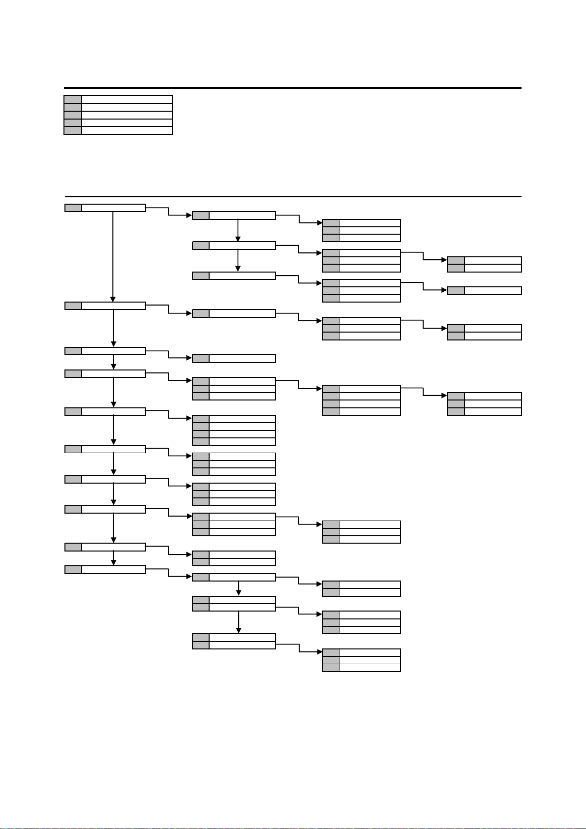
6.2.5 Parameters submenu
LEVEL 2 LEVEL 3 LEVEL 4 LEVEL 5
T. BURGLAR ALARM
T. PRE-ALARM
T. EMERGENCY ALARM
ALARM COUNT
T. LACK OF POWER
6.2.6 Telephone dialer submenu
LEVEL 2 LEVEL 3 LEVEL 4 LEVEL 5
PHONE NUMBERS
VOCAL MESSAGES
SMS MESSAGES
SENDING MODE
PSTN PARAMETERS ... ...
GSM PARAMETERS
PSTN LINE TEST
PERIOD COMM TEST
RE. CTRL BACKUP
ADVANCED
TEL. NUMBER
ASSIGN TEL. N.
PHONE LINE
MESSAGES LIST
WRITE SMS
T01:
T02: VOCAL
... IDP BURGLAR
NATION
PABX CONNECTION
TONE LINE CHECK
ANSWER CONTROL
SIM PIN
SIM CARD EXPIRY
INCOMING SMS
24 H
SYSTEM ON
DISABLE
24 H
SYSTEM ON ASSIGN TEL. N.
DISABLE SET HOUR
ENABLE
DISABLE
ANSWER MACHINE
REM. CTRL CODE
RETURN CALL
CALL TIME DELAY
PHONE LINE ENABLE
T01:
T02:
…
T01:
T02: SYSTEM
... ZONES
T01:
T02: SELECT LINE
...
BASE MESSAGE
BURGLAR PLAY
... RECORDING
ADF TECHNOL. TYPE 1
INTERVAL
PSTN
GSM
RET. CALL DISABLE
RET. CALL TYPE A
RET. CALL TYPE B
PSTN LINE
GSM LINE
LAN NETWORK
DS1067-035A 90 LBT8633
Page 91
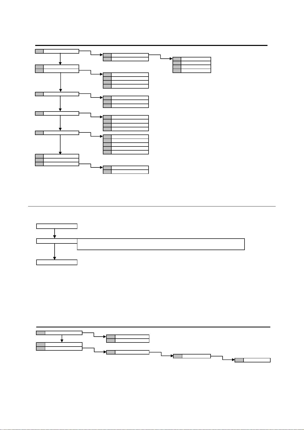
6.2.7 Maintenance submenu
I
dif
I
LEVEL 2 LEVEL 3 LEVEL 4 LEVEL 5
LANGUAGE
ACQUIRE ...
DELETE ROMANA
RADIO DEVICES
SHOW ADDRESSES
SW. REL.
PARTIAL RESET
GLOBAL RESET
DATA TRANSFER
KP 01:KP 01
... ITALIANO
EXPANSIONS
KEYPADS
READERS
RADIO DEVICES
ACQUIRE
CONFIGURATION
DELETE
EXPANSIONS
KEYPADS
READERS
RADIO DEVICES
CONTROL PANEL
EXPANSIONS
KEYPADS
READERS
RADIO DEVICES
SAVE SETTINGS
RESTORE SETTINGS
ENGLISH
6.3 USER MENU
Start selections in User menu are:
SYSTEM STATUS
EVENT LOG
t shows the system status and it allows to mo
It allows to read the list of events stored into control panel
(see § 6.1.1 Event log submenu).
SETTINGS
t allows to exclude the zones, change your code and name code
Depending on choice made, other menu tree items can be accessed, as shown below.
Except for the State system, all of the items are accessible only when the system is not active (see § 4.1.2).
6.3.1 Settings Submenu
LEVEL 2 LEVEL 3 LEVEL 4 LEVEL 5
EXCLUDE / INCLUDE
CHANGE CODE
USERS
In01: ...
In02: ...
CONFIGURE USER
y zones status
UTnn: ...
NAME
DS1067-035A 91 LBT8633
Page 92
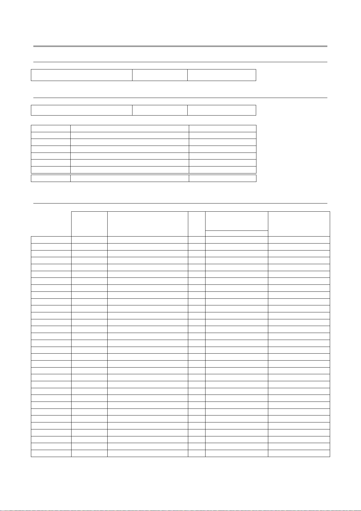
7 PROGRAMMING SUMMARY TABLES AND FACTORY SETTING
7.1 INSTALLER MENU
System code (for FastPro) Default : 99999999
7.2 ZONES
Zones number Default : 1
Name Type
1
2
3
4
5
6
Default Standard
7.3 USERS
Associated zones
Default
Installer 000000
Master 111111
User 2 000020
User 3 000030
User 4 000040
User 5 000050
User 6 000060
User 7 000070
User 8 000080
User 9 000090
User 10 000100
User 11 000110
User 12 000120
User 13 000130
User 14 000140
User 15 000150
User 16 000160
User 17 000170
User 18 000180
User 19 000190
User 20 000200
User 21 000210
User 22 000220
User 23 000230
User 24 000240
User 25 000250
User 26 000260
User 27 000270
User 28 000280
User 29 000290
User 30 000300
User 31 000310
Name
--
Enabled
x
1 2 3 4 5 6
SYSTEM
SYSTEM
□ x □ □ □ □ □
□
□
□
□
□
□
□
□
□
□
□
□
□
□
□
□
□
□
□
□
□
□
□
□
□
□
□
□
□
x □ □ □ □ □
x □ □ □ □ □
x □ □ □ □ □
x □ □ □ □ □
x □ □ □ □ □
x □ □ □ □ □
x □ □ □ □ □
x □ □ □ □ □
x □ □ □ □ □
x □ □ □ □ □
x □ □ □ □ □
x □ □ □ □ □
x □ □ □ □ □
x □ □ □ □ □
x □ □ □ □ □
x □ □ □ □ □
x □ □ □ □ □
x □ □ □ □ □
x □ □ □ □ □
x □ □ □ □ □
x □ □ □ □ □
x □ □ □ □ □
x □ □ □ □ □
x □ □ □ □ □
x □ □ □ □ □
x □ □ □ □ □
x □ □ □ □ □
x □ □ □ □ □
x □ □ □ □ □
Code
DS1067-035A 92 LBT8633
Page 93
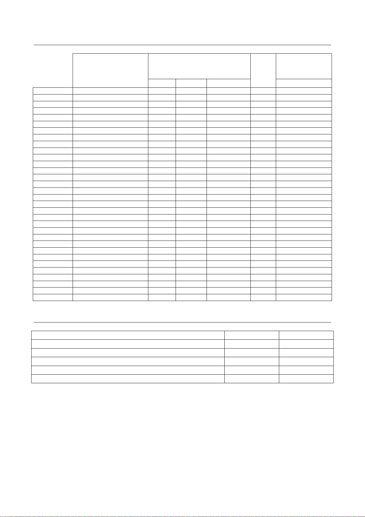
7.4 KEYS
Function Associated Zones
Key 1
Key 2
Key 3
Key 4
Key 5
Key 6
Key 7
Key 8
Key 9
Key 10
Key 11
Key 12
Key 13
Key 14
Key 15
Key 16
Key 17
Key 18
Key 19
Key 20
Key 21
Key 22
Key 23
Key 24
Key 25
Key 26
Key 27
Key 28
Key 29
Key 30
Key 31
Key 32
Name
Zones Accesses Zones - Accesses
□
□
□
□
□
□
□
□
□
□
□
□
□
□
□
□
□
□
□
□
□
□
□
□
□
□
□
□
□
□
□
Enabled
□
1 2 3 4 5 6
x □ □ □ □ □
x □ □ □ □ □
x □ □ □ □ □
x □ □ □ □ □
x □ □ □ □ □
x □ □ □ □ □
x □ □ □ □ □
x □ □ □ □ □
x □ □ □ □ □
x □ □ □ □ □
x □ □ □ □ □
x □ □ □ □ □
x □ □ □ □ □
x □ □ □ □ □
x □ □ □ □ □
x □ □ □ □ □
x □ □ □ □ □
x □ □ □ □ □
x □ □ □ □ □
x □ □ □ □ □
x □ □ □ □ □
x □ □ □ □ □
x □ □ □ □ □
x □ □ □ □ □
x □ □ □ □ □
x □ □ □ □ □
x □ □ □ □ □
x □ □ □ □ □
x □ □ □ □ □
x □ □ □ □ □
x □ □ □ □ □
x □ □ □ □ □
7.5 GENERAL PARAMETERS
Parameter Value Default
Burglar alarm time (burglar, tamper, panic) 180 s
Pre-alarm time 180 s
Emergency alarm time 180 s
Alarms count disabled
Lack of power time 1h
DS1067-035A 93 LBT8633
Page 94
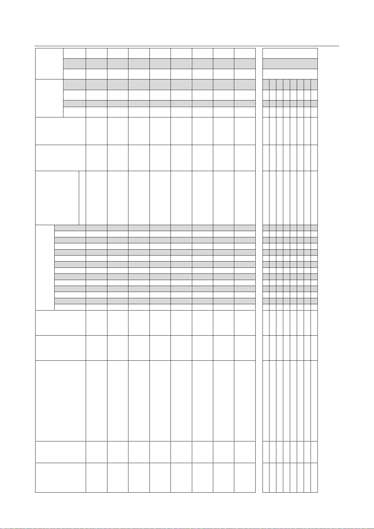
7.6 CONTROL PANEL INPUTS
Attrib.
Ancill.
Funct.
Bypass
allowed
Common
input
Release
type
Door
opening
Courtesy
light
Gong
Absence
of move
YES
SINGLE
OR
Video assign
AND input
□
□
to zones
Association
Input of test
Failure
Tamper
Key
Emergency
Reset fire al.
Hold-up
Silent Panic
Panic
Customize
Pre-alarm
Technol.
Fire alarm
Delayed X
Immediate X X X X X X X
Sensitivity
□
□
□
□
1 2 3 4 5 6
□
□
□
□
□
□
□
□
□
□
□
□
□
□
□
□
□
□
□
□
□
□
□
□
□
□
□
□
□
□
□
□
□
□
□
□
□
□
□
□
□
□
□
□
□
□
□
x
DEFAULT
□
□
□
□
□
x
□
□
□
□
□
□
□
□
□
□
□
□
□
□
□
x
x
x
□
□
□
□
□
□
□
□
□
□
□
□
□
□
□
x
x
x
Type*
Name
Logical address
Physical address
I01
I02
I03
I04
I05
I06
I07
I08
D.Bal.
D.Bal. D.Bal.
...
...
01
02
I 01
I 02
...
03
I 03
D.Bal.
...
04
I 04
D.Bal.
...
05
I 05
D.Bal.
...
06
I 06
D.Bal.
...
07
I 07
D.Bal.
...
08
I 08
Types: Not used (N.U.), Normally closed (N.C.), Normally open (N.O.), Balanced (S.Bal.), Double balancing (D.Bal.), Shock (SH), Roller (ROL.)
If Shock or Roller if requested the sensitivity.
DS1067-035A 94 LBT8633
Page 95
7.7 CONTROL PANEL OUTPUTS
□
□
□
□
□
Association to
If Commandable
to zones
Association
Burglar/Tamper
Failure
Courtesy light
Door opening
Commandable
Commandable pulsed
Excluded Inputs
Open input
Arm warning
OR TC
AND TC
Zones status
Buzzer
Gong
Lack of power
Low Battery
Customize
Tel. failure
System failure
Reset fire alarm
Fire alarm
Technol.
Emergency
Hold-up
Panic
Silent Panic
Tamper
Reset burglar
Pre-alarm
Burglar alarm
Phone numbers
□
□
□
□
□
□
1 2 3 4 5 6 7 8 9 10 11 12
□
□
□
□
□
□
□
1 2 3 4 5 6
x
x
x
x
x
x
□
□
□
□
□
□
□
□
□
□
□
□
□
□
□
□
□
□
□
□
□
□
□
□
□
□
□
□
□
□
□
□
□
□
□
□
□
□
□
□
□
□
□
□
□
□
□
□
□
□
□
□
□
□
□
□
□
□
□
□
□
□
□
□
□
□
□
□
□
□
□
□
□
□
□
□
□
□
□
□
□
□
□
□
□
□
□
□
SYSTEM
□
SYSTEM SYSTEM
SYSTEM SYSTEM
SYSTEM
□
DEFAULT
Type*
N.H.
N.H. N.H.
N.H.
N.H.
N.H.
Name
U5
U6
01
02
03
04
05
06
U1
U2
U3
U4
U5
U6
Types: Not used (N.U.), Normally open (N.L.), Normally closed (N.H.)
Logical address
Physical address
U1
U2
U3
U4
DS1067-035A 95 LBT8633
Page 96
7.8 EXPANSION INPUTS
u
ct
A
Bypass allowed
Common input
Attrib.
Release type
Door opening
.
Coutesy light
n
Gong
Ancill.
F
bs. of move
Video assign
AND input
to zones
Association
Input of test
Failure
Tamper
Key
Emergency
Reset fire alarm
Hold-up
Silent Panic
Panic
Customize
Pre-alarm
Technol.
Fire alarm
Delayed
Immediate
YES
OR
SINGLE
□
□
□
□
□
□
□
□
□
□
□
□
1 2 3 4 5 6
X
X X X X X X X
□
□
□
□
□
□
□
□
□
□
□
□
□
□
□
□
□
□
□
□
□
□
□
□
□
□
□
□
□
□
□
□
□
□
□
□
□
□
□
□
□
□
□
□
□
□
□
□
□
□
□
□
□
□
□
□
□
□
□
□
□
□
□
□
□
□
□
□
□
□
□
□
□
□
□
□
□
□
□
□
□
□
□
□
□
□
□
□
□
□
□
□
□
□
□
□
□
□
□
□
□
□
□
□
□
□
□
□
□
□
□
□
□
□
□
□
□
□
□
□
□
□
□
□
□
□
□
□
□
□
□
□
□
□
□
□
□
□
□
□
□
□
□
□
x
x
□
□
□
□
□
□
□
□
□
□
□
□
□
x
x
x
□
□
□
□
□
□
□
□
□
□
□
□
□
□
□
x
x
x
Sensitivity
Type*
Name
Logical
address
Physical
address
D.Bal.
D.Bal.
I n1
I n2
I n3
I n4
I n5
I n6
I n7
I n8
I n1
Expansion 1 Expansion 2 Expansion 3 DEFAULT
I n2
I n3
In4
I n5
I n6
I n7
I n8
I n1
I n2
I n3
I n4
I n5
I n6
I n7
I n8
I n1
I n2
D.Bal.
D.Bal.
I n3
I n4
D.Bal.
D.Bal.
I n5
I n6
D.Bal.
D.Bal.
I n7
I n8
DS1067-035A 96 LBT8633
Page 97
7.9 EXPANSION OUTPUTS
□
□
□
□
□
□
□
□
U1
□
□
□
□
□
□
□
□
□
□
□
□
□
□
□
□
□
□
□
□
□
□
□
□
□
□
□
□
□
□
□
□
□
□
□
U2
U3
□
□
□
□
□
□
U2
□
□
□
□
□
□
□
□
□
□
□
□
□
□
□
□
□
□
□
□
□
□
□
□
□
□
□
□
□
□
□
□
□
U3
□
□
□
□
U3
□
□
□
□
□
□
□
□
□
□
□
□
□
□
□
□
□
□
□
□
□
□
□
□
□
□
□
□
□
□
□
U1
□
□
□
□
□
□
1 2 3 4 5 6 7 8 9 10 11 12
□
□
□
□
Association to
phone numbers
If commandable
□
□
to zones
Association
Burglar/Tamper
Failure
Courtesy light
Door opening
Commandable
Commandable pulsed
Excluded Input
Open input
Arm warning
OR TC
AND TC x
Zones status
Buzzer
Gong
Lack of power
Low Battery
Customize
Tel. failure
System failure
Reset fire alarm
Fire alarm
Technol.
Emergency
Hold-up
Panic
Silent Panic
Tamper x
Reset burglar alarm
Pre-alarm
Burglar alarm x
Type*
Name
Logical address
Physical address
□
□
□
□
1 2 3 4 5 6
□
□
□
□
□
□
□
□
□
□
□
□
□
□
□
□
□
□
□
□
□
□
□
□
□
□
□
□
□
U1
U2
EXP 1 EXP 2 EXP 3 DEFAULT
SYSTEM
SYSTEM
N.H.
N.H.
seq
seq
U1
U2
SYSTEM
N.H.
seq
U3
DS1067-035A 97 LBT8633
Page 98
7.10 KEYPADS INPUTS
KP1 KP 2 KP 3 KP 4 KP 5 KP 6 KP 7 KP 8
Bypass allowed
Common input
Attrib.
Release type
Door opening
Courtesy light
Gong
Ancill.
Funct.
Absence of move
Video assign
AND input
to zones
Association
Input test
Failure
Tamper
Key
Emergency
Reset fire alarm
Hold-up
Silent Panic
Panic
Customize
Pre-alarm
Technol.
Fire alarm
Delayed
Immediate
Sensitivity
Type*
Name
Logical address
Physical address
□
□
□
□
□
□
□
□
□
□
□
IN1
□
IN1
1 2 3 4 5 6
□
□
□
□
□
□
IN1
□
□
□
□
□
□
IN1
□
□
□
□
□
□
IN1
□
□
□
□
□
□
IN1
□
□
□
□
□
□
□
□
□
□
□
□
IN1
IN1
Default: All keypads inputs are configured as “NOT USED”
DS1067-035A 98 LBT8633
Page 99
7.11 RADIO EXPANSION INPUTS
Bypass
allowed
Common input
Attrib.
Release type
Door opener
Courtesy light
Gong
Funz.Compl
Abs. of move.
Video assign
AND input
to zones
Association
Failure
Tamper
Key
Emergency
Reset fire alarm
Hold-up
Silent panic
Audible Panic
Pre-alarm
Customization
Technol. Type 1
Fire alarm
Delayed
Immediate
□
□
□
□
□
□
□
□
□
□
□
□
□
□
□
□
□
□
□
□
□
□
□
□
□
□
□
□
□
□
□
□
□
□
□
□
□
□
□
□
□
□
□
□
□
□
□
□
□
□
□
□
□
□
□
□
□
□
□
□
□
□
□
□
□
□
□
□
□
□
□
□
□
□
□
□
□
□
□
□
□
□
□
□
□
□
□
□
□
□
□
□
1 2 3 4 5 6
□
□
□
□
□
□
□
□
□
□
□
□
□
□
□
□
□
□
□
□
□
□
□
□
□
□
□
□
□
□
□
□
□
□
□
□
□
□
□
□
□
□
□
□
□
□
□
□
□
□
□
□
□
□
□
□
□
□
□
□
□
□
□
□
□
□
□
□
□
□
□
□
□
□
□
□
□
□
□
□
□
□
□
□
□
□
□
□
□
□
□
□
□
□
□
□
□
□
□
□
Physical
Type*
Name
Logical
address
address
Device
I n1
IR
1
I n2
DC
I n1
IR
2
I n2
DC
I n1
IR
3
I n2
DC
I n1
IR
4
I n2
DC
I n1
IR
5
I n2
DC
I n1
IR
6
I n2
I n1
I n2
IR
DC
DC
7
Radio Expansion 1
I n1
IR
8
I n2
DC
I n1
IR
9
I n2
DC
I n1
IR
10
I n2
DC
I n1
IR
11
I n2
DC
I n1
IR
12
I n2
DC
I n1
IR
13
I n2
DC
I n1
IR
14
I n2
DC
I n1
IR
15
I n2
DC
I n1
IR
I n2
DC
16
DS1067-035A 99 LBT8633
Page 100
7.12 RADIO EXPANSION OUTPUTS (SIRENS)
Name
Logical address
Physical address
Outputs
to zones
Association
Fire alarm
Audible panic
Tamper
Pre alarm
CUSTOMIZATION
Burglar
Siren + Blink
Blink
report
Status
Disabled
U1
□
□
□
□
□
1 2 3 4 5 6
□
U2
seq
SYSTEM
x
x
Expansion 1 DEFAULT
DS1067-035A 100 LBT8633
 Loading...