

Page 1

Urma Digiset 5
USERMANUAL
Version 1.0 e
Page 2

digiset 5
Urma AG, Switzerland www.urma.ch page 2
The information contained in this document may not be amended without prior notification. Urma AG will therefore not accept any liability.
Urma AG disclaim all warranties, any legal responsibility or any liability for consequential damages arising from or in connection with the content or use of this manual.
Furthermore, Urma AG hereby disclaim all warranties, any legal responsibility or any
liability for consequential damages arising from the incorrect use of the hardware
and/or software.
The layout or design of the hardware can be changed without prior notice. Urma AG
will therefore not accept any liability.
All other trademarks and product designations used in this manual are the property of
the respective companies and manufacturers.
Urma AG waive all property rights with regard to the named trademarks and product
designations that do not belong to them.
Page 3

digiset 5
Urma AG, Switzerland www.urma.ch page 3
Table of contents
1 IMPORTANT NOTES _______________________________________________ 5
1.1 DELIVERY SCHEDULE _____________________________________________ 5
1.2 PURPOSE ______________________________________________________ 6
2 SAFETY INSTRUCTIONS ___________________________________________ 7
2.1 GENERAL SAFETY INSTRUCTIONS _____________________________________ 7
3 COMPATIBILITY STATEMENT _______________________________________ 8
3.1 E
LECTROMAGNETIC COMPATIBILITY (EMC) _____________________________ 8
4 SETUP INSTRUCTIONS ____________________________________________ 9
4.1 U
NPACKING AND START UP _______________________________________ 9
4.1.1 Unpacking______________________________________________________________ 9
4.1.2 Assembling and setup of Digiset 5 __________________________________________ 10
4.2 CALIBRATION OF PRESETTER ______________________________________ 12
4.2.1 Set the camera’s working distance________________________________________ 12
4.2.2 Check illumination ____________________________________________________ 13
4.2.3 Align camera ________________________________________________________ 15
4.2.4 Adjust X- and Z-Parallelity ______________________________________________ 16
4.2.5 Set absolute zero point ________________________________________________ 17
5 COMMISSIONING ________________________________________________ 18
5.1 OPERATING DIGISET 5____________________________________________ 18
5.1.1 Menu bar (Main menu) ___________________________________________________ 19
5.1.2 Live picture ____________________________________________________________ 20
5.2 STATUS FIELD__________________________________________________ 22
5.2.1 Status and system information _____________________________________________ 22
5.2.2 Various methods of displaying readings on the TCAM2__________________________ 23
6 CONFIGURATION (SOFTWARE SETUP)______________________________ 25
6.1 I
NFO_________________________________________________________ 25
6.2 IMAGING ______________________________________________________ 26
6.2.1 Coordinate system (optional) ______________________________________________ 26
6.2.2 Black/White____________________________________________________________ 26
6.2.3 Brightness (optional)_____________________________________________________ 27
6.2.4 Inverse tool ____________________________________________________________ 27
6.2.5 Imaging parameters _____________________________________________________ 27
6.3 SERIAL INTERFACE (COUNTER MODULE) _______________________________ 28
6.4 OUTPUT FORMAT _______________________________________________ 29
6.5 MEASURING SYSTEMS ____________________________________________ 30
6.6 CORRECTIONS _________________________________________________ 31
6.6.1 Linear correction (optional)________________________________________________ 31
6.6.2 Parallel correction_______________________________________________________ 31
6.6.3 Absolute zero point (optional)______________________________________________ 31
Page 4

digiset 5
Urma AG, Switzerland www.urma.ch page 4
6.7 OPTIONS _____________________________________________________ 32
6.8 PASSWORD ___________________________________________________ 32
6.9 DATE AND TIME (OPTIONAL)________________________________________ 33
6.10 MAINTENANCE AND SERVICE ______________________________________ 33
7 SYSTEM ________________________________________________________ 34
7.1 TOOL REFERENCES ______________________________________________ 34
7.1.1 Select tool references____________________________________________________ 34
7.1.2 Manage tool references __________________________________________________ 34
7.2 TOOLS _______________________________________________________ 36
7.2.1 Select tool_____________________________________________________________ 36
7.2.2 Manage tools __________________________________________________________ 36
7.3 TOOL LIST ____________________________________________________ 38
7.4 POST PROCESSOR-MEASUREMENT SERIES (OPTIONAL) ____________________ 39
7.4.1 New _________________________________________________________________ 39
7.4.2 Cancel _______________________________________________________________ 39
7.4.3 Interrupt ______________________________________________________________ 40
7.4.4 Continue ______________________________________________________________ 40
7.4.5 Output________________________________________________________________ 40
7.4.6 Show list ______________________________________________________________ 40
8 IMAGING _______________________________________________________ 41
8.1 STARTING IMAGING ______________________________________________ 41
8.1.1 Camera 2 (optional) _____________________________________________________ 41
8.2 MEASURING METHODS ___________________________________________ 42
8.2.1 Fixed axis _____________________________________________________________ 42
8.2.2 Maximum _____________________________________________________________ 43
8.2.3 Preset ________________________________________________________________ 44
8.2.4 Measure centre_________________________________________________________ 45
8.3 M
EASURING PROCEDURES_________________________________________ 46
8.3.1 Principal procedures in contour analysis _____________________________________ 46
8.3.2 Detailed description of measuring procedures _________________________________ 47
8.4 MEASURING PROGRAMS / MEASURING FUNCTIONS _______________________ 51
8.4.1 Line__________________________________________________________________ 51
8.4.2 Angle ________________________________________________________________ 52
8.4.3 Radius _______________________________________________________________ 52
8.4.4 With measure centre ____________________________________________________ 52
9 INDEX __________________________________________________________ 53
10 APPENDIX 1 / PASSWORD________________________________________ 54
Page 5
digiset 5
Urma AG, Switzerland www.urma.ch page 5
1 Important notes
1.1 Delivery schedule
The Digiset 5 imaging system is supplied with the following components:
• Digiset 5 measuring unit
• Zero point mandrel
• Power cord
• TCAM2 with integral electronic analysis devices and colour LCD
• Telecentric CMOS camera
• Telecentric LED light
• Desk top power pack
• USER manual on CD-ROM
• Quick start manual (outside of the wood box)
• Dustcover
• Certification of conformity and warranty certificate
Please check the contents of the package directly after delivery.
Please contact us immediately if the contents as described above are not correct.
In case of transportation damages take immediately contact with the forwarder.
Page 6

digiset 5
Urma AG, Switzerland www.urma.ch page 6
1.2 Purpose
The Digiset 5 is a standalone, complete imaging system for automatic measuring of
contours, especially for automatic measuring of tool cutting edges to calculate relevant geometrical data.
The object to be measured is displayed as a live picture on the bright, 10.4” screen
as well as the geometrical data automatically calculated for the object and the readings of the measuring systems connected.
The Digiset 5 has a simple menu control system, just like the ones used in common
Office applications, operated with a PS2 mouse. All functions can be selected simply
and easily using the menu bar.
Page 7
digiset 5
Urma AG, Switzerland www.urma.ch page 7
2 Safety instructions
2.1 General safety instructions
The following instructions must be carefully observed before installing and commissioning the TCAM2 imaging components, CMOS camera and light and if necessary
the counter module.
1. Imaging components may only be installed by specially trained personnel.
2. Use the optional power pack adapted for the components’ connection
data to supply power to the equipment.
3. The guarantee does not cover any damage to the imaging components
caused by using your own power supply.
4. The TCAM2 must be connected last in order to protect system components from damage.
Keep this user manual carefully for later use and observe the following safety and
operating instructions.
1. Do not expose the Digiset 5 to direct sunlight.
2. Do not expose the Digiset 5 to excessive damp and do not pour fluids
over the equipment.
3. All maintenance work must only be carried out by authorized customer
service personnel.
Page 8
digiset 5
Urma AG, Switzerland www.urma.ch page 8
3 Compatibility statement
Manufacturer: Urma AG, Werkzeugfabrik
Obermatt 3
CH-5102 Rupperswil/Switzerland
Name of unit: UrmaDigiset 5
Unit type: Image processing
3.1 Electromagnetic compatibility (EMC)
The TCAM2 meets the conditions of standards EN 550011 and EN 50082-2.
These threshold values give sufficient protection against dangerous electromagnetic
radiation for the environment. This applies as long as the product has been fitted and
used in accordance with the instructions. It is also necessary for all cables to the
TCAM2 to be shielded and connected properly. The electronic analysis unit must
also be shielded and earthed.
Operating with incorrectly shielded cables can lead to electromagnetic interference.
All changes or modifications that are not expressly approved by
the manufacturer will lead to the operating licence being null and
void.
Page 9
digiset 5
Urma AG, Switzerland www.urma.ch page 9
4 SETUP INSTRUCTIONS
4.1 Unpacking and start up
The device is delivered in a wood box. The transport holder (red screw head) is located on the top side of the measurement tower.
4.1.1 Unpacking
1.1 Loosen the top cover of the wood box and lift it up. (Pic. 1)
1.2 There are two compartments inside the box filled with accessories.
Carefully unpack these accessories first. (Pic. 2)
1.3 Loosen the locking screws at the bottom of the wood box (marked
with black colour)
1.4 You can now lift the frame of the box vertically up over the measurement tower. (Pic. 3)
1.5 Take away the protection film and check the device. Report any visible transport damage without delay to your supplier or shipper.
1.6 Lift the device up with two persons.
Don’t touch the camera or light to lift up.
This may instantly damage the unit!
1.7 Place the device on a flat, stable base.
Pic. 1
Pic. 2
Pic. 3
Page 10
digiset 5
Urma AG, Switzerland www.urma.ch page 10
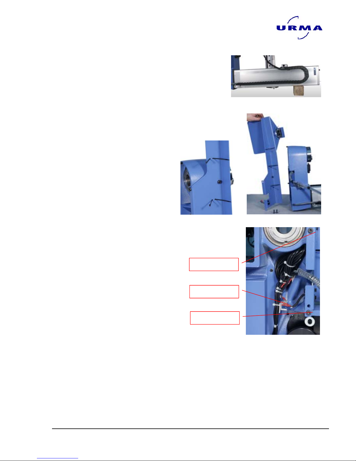
4.1.2 Assembling and setup of Digiset 5
1. Check the handwheel for the x-axes is dissassembled.
2. Get a piece of wood or a similar, strong block (about
100x100x200mm / 4x4x8 in)
3. Carefully flip the Digiset as shown in Pic. 4
(make sure no parts get damaged)
4. Take the metal frame and put in the cable binder as
shown in Pic. 5 and 5a (it is difficult to put them in after
mounting the metal frame)
5. Assemble the metal frame to the Digiset 5 body as shown
in Pic. 6 and connect the blue and red cables.
Pic. 4
Pic. 5
Pic. 5a
Pic. 6
Blue and red cables
Assembling screw
Assembling screw
Page 11
digiset 5
Urma AG, Switzerland www.urma.ch page 11
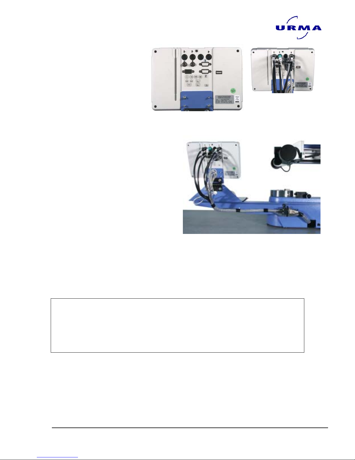
6. Flip the Digiset to its
normal horizonta position and mount the
screen to the metal
frame and connect cables (Pic. 7 and 7b) according to the number
tags.
7. Check once again whether all cables are pluged correctly.
8. Connect the unit with the transformer and put the power cord to the power
supply
9. Remove the security screw from the top of the tower
10. Switch on the unit and start with the basic settings
NOTE:
Never place the device in the immediate vicinity of the following machines and
devices:
EDM machines
Electrical welding equipment
Circuit breakers and switches
Electrostatic painting systems and similar fixtures
Pic. 7
Pic. 7b
Pic. 7
Page 12
digiset 5
Urma AG, Switzerland www.urma.ch page 12
4.2 Calibration of Presetter
4.2.1 Set the camera’s working distance
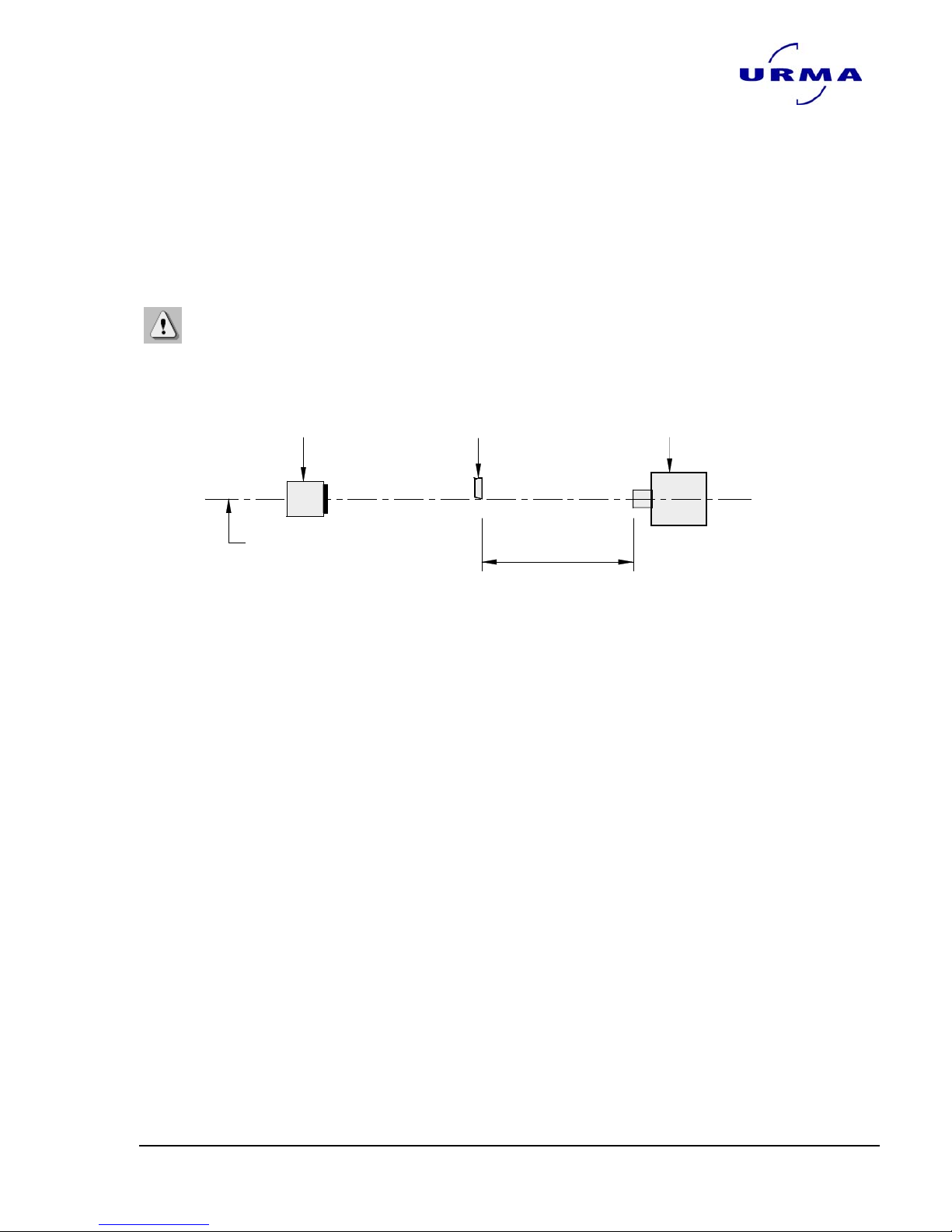
The working distance is defined as the distance between the front edge of the camera tube shield and the object to be measured, for example a tool cutting edge.
This measurement is preset by the design and the production tolerances of the camera tube shield (lens).
The working distance must be set following the instructions in the
enclosed calibration log with a permissible tolerance of 100 ±
0.1mm. (3.937 ± .004”)
Object to be
measured
Working distance
Illumination
Optical axis
Camera
Aligning the camera and the lamp
Page 13
digiset 5
Urma AG, Switzerland www.urma.ch page 13
4.2.2 Check illumination
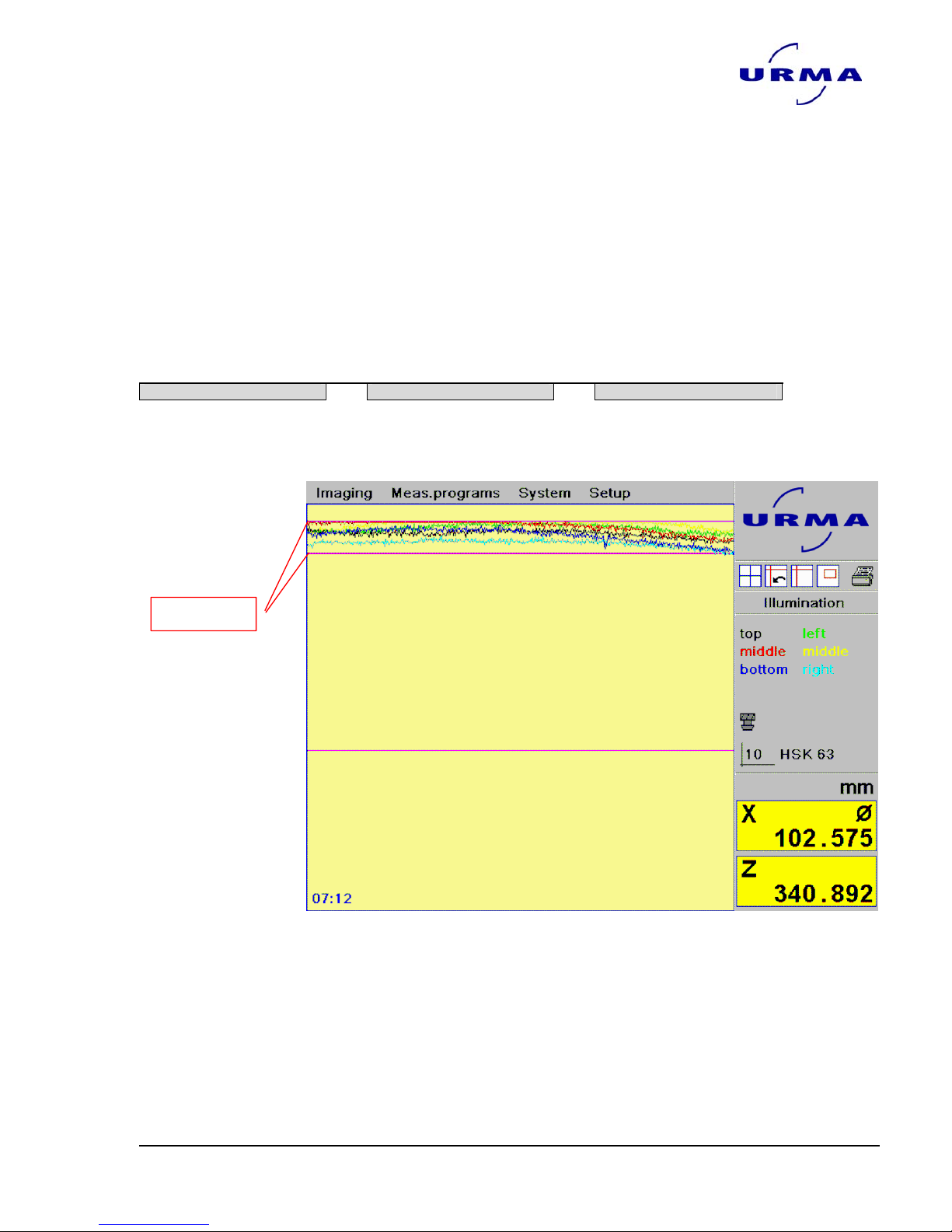
After the working distance is checked, the homogeneity and brightness of the illumination must be set. For this, you must not have anything in the camera’s visual field.
To check the illumination the greyscales are checked in the camera’s horizontal and
vertical alignment on both edges of the image as well as the middle of the image and
the results shown on 6 lines.
The illumination reaches its optimum setting if these lines are as horizontal as possible and within the horizontal tolerance range marked by 2 purple lines.
You access the operating mode for setting the illumination using the following menu
steps:
Main menu Sub-menu 1 Sub-menu 2
Setup
Ö
Imaging
Ö
Illumination
The TCAM2 displays the following image with 6 grey scales (illumination lines):
Procedure:
1. Select the illumination check with the "Illumination" operating mode. The
horizontal tolerance field appears with the illumination lines. "Illumination"
appears in the status window.
2. If not all 6 greyscale lines on the LCD are inside the tolerance field, you
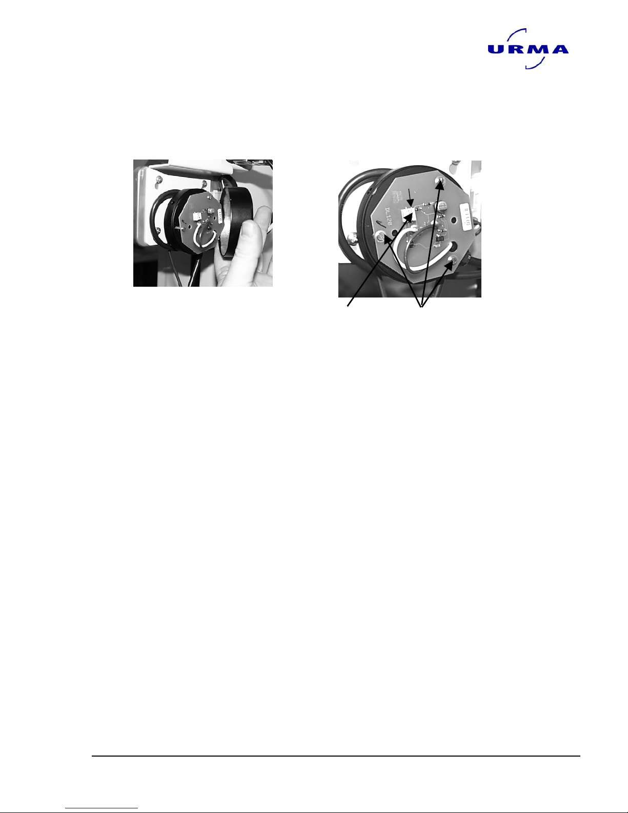
have to adjust the light source. Remove the cover of the light source as
shown on the picture below.
Tolerance field
Page 14
digiset 5
Urma AG, Switzerland www.urma.ch page 14
3. If the greyscale lines are not horizontal you have to adjust the position of the
light to the optical axis. For this you unscrew the 3 slotted-head screws until
you can move the whole print. On the screen you will see what the movement of the print will cause with the greyscale lines. You move the print until
all greyscale lines are horizontal.
Potentiometer slotted head screws
4. If the greyscale lines are horizontal but not within the tolerance field, you can
increase or reduce the intensity of the light on turning the little screw on the
potentiometer.
5. Put back the cover and exit the illumination check with ESC or by selecting
another operating mode.
Page 15
digiset 5
Urma AG, Switzerland www.urma.ch page 15
4.2.3 Align camera
When aligning the camera you must ensure that a known straight contour running parallel
to the vertical axis of your system also runs parallel to the vertical axis of the cross hairs in
the TCAM2.
You access this operating mode using the following menu steps:
Main menu Sub-menu 1 Sub-menu 2
Setup
Ö
Imaging
Ö
Align camera
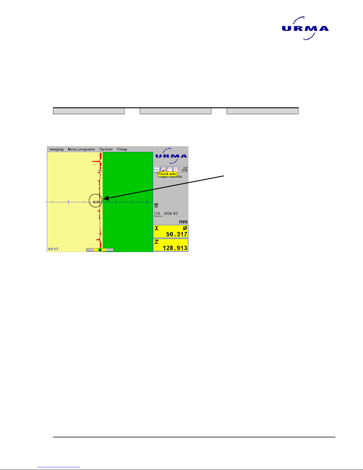
The TCAM2 then displays a histogram that shows the deviation away from the vertical
axis.
The displayed value for the angle should be
less than 0.02 °
Procedure:
1. Set the master mandrill on the screen it is not necessary to set in the centre.
2. Select the "Align camera" operating mode. The TCAM2 then goes into the
"Align camera" operating mode and you will see a histogram along the vertical axis of the cross hairs. "Align camera" appears in the status window.
3. Turn the camera on its support around the optical axis until the histogram
has the smallest possible deviation.
)
Page 16
digiset 5
Urma AG, Switzerland www.urma.ch page 16
4.2.4 Adjust X- and Z-Parallelity
You access this operating mode using the following menu steps:
Main menu Sub-menu 1 Sub-menu 2
Setup
Ö
Corrections
Ö
Parallel correction
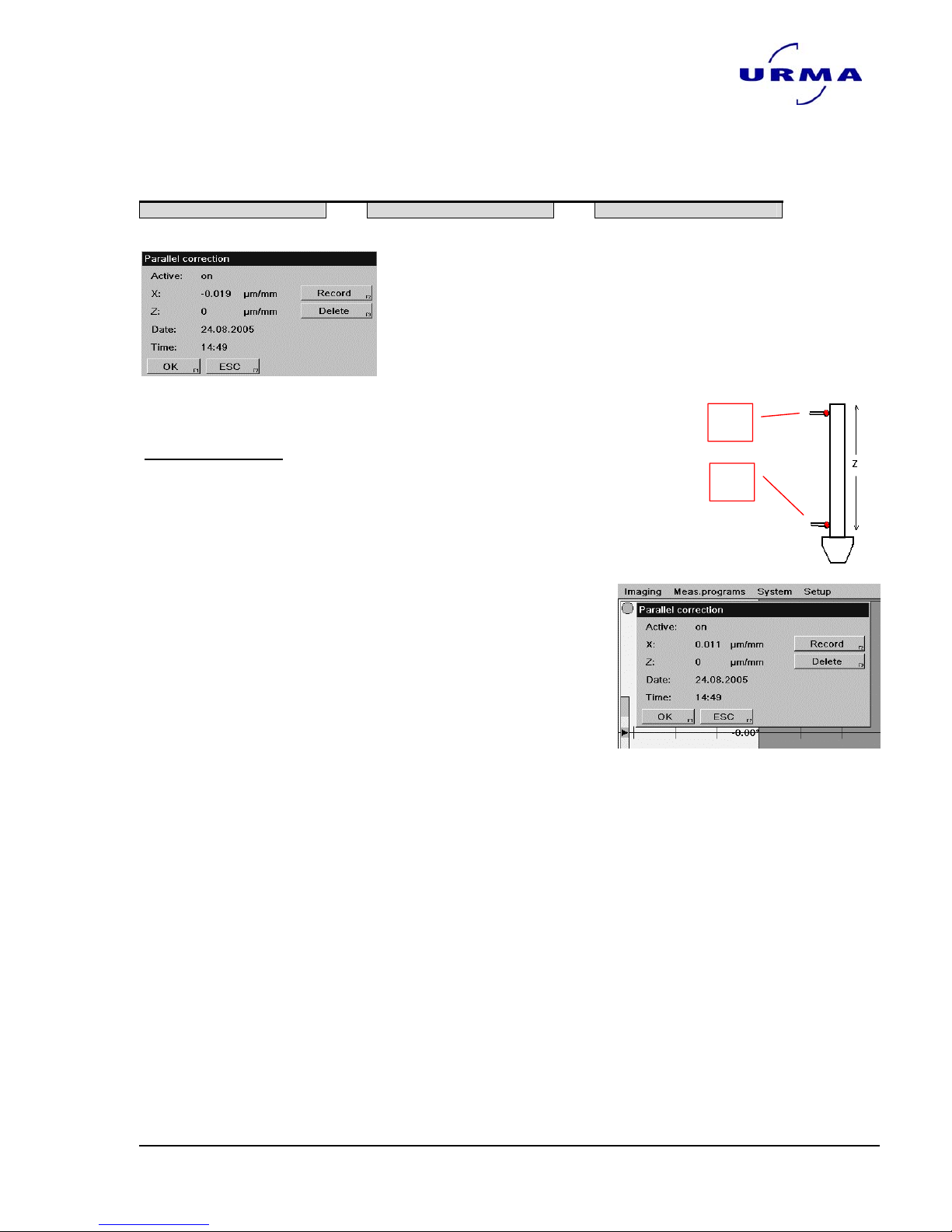
The axis of the calculated correction values is
automatically allocated by the system with parallel
correction.
X-axis parallelity
1. Insert calibration bar into the Digiset spindle
2. Switch on the Digiset
3. Move the measuring arm in both axis
4. Move the measuring arm to the upper position (A)
5. Click SETUP on the menubar; Æ Corrections Æ
Parallel correction
6. The window “Parallel correction” must show “on” for
Active. Otherwise change it
7. Click on “Record”
8. the screen shows “1. Point”
9. Measure the first point (A) and click OK
10. Move the measuring arm to its lower position (B)
11. Measure the second point and click OK
12. click OK to complete the procedure.
The parallelity for the Z-axis is installed in the factory.
A
B
Page 17
digiset 5
Urma AG, Switzerland www.urma.ch page 17
4.2.5 Set absolute zero point
You access this operating mode using the following menu steps:
Main menu Sub-menu 1 Sub-menu 2
Setup
Ö
Corrections
Ö
Absolute zero point
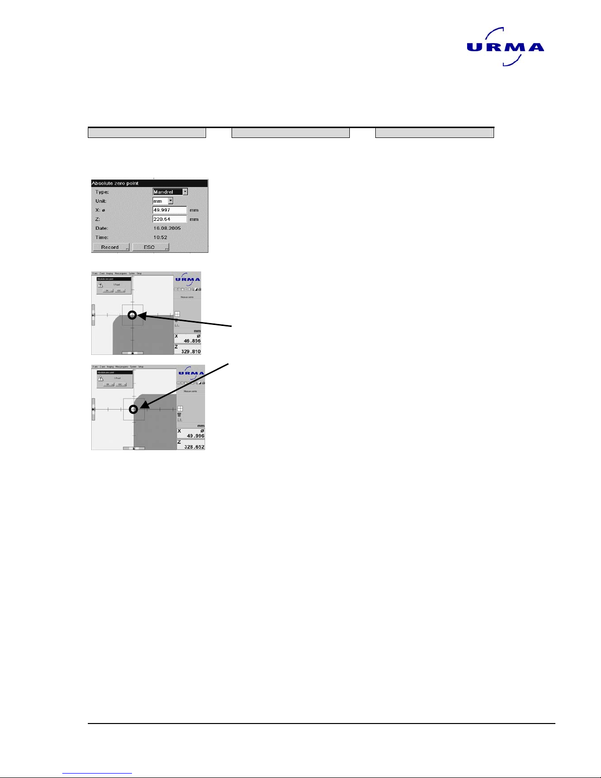
The absolute zero point is the reference point for all stored
tool references.
For this reason, before saving tool references, it is necessary to store the absolute zero point as follows.
1. When you click on the menu point “absolute zero point”
it will appear the window on the left. Enter the known
dimensions of the master mandrill.
2. Press on the Record bottom on this window and it will
open a new Window showing “1.point”
3. Move the horizontal line of master mandrel to the center of the reticule ( You are in the “measure centre”
mode ) to measure the length. Click “OK”.
4. Move the vertical line of the master mandrel to the center of the reticule to measure the diameter. Click “OK”.
After this, the system stays in the measure centre
mode and you can check the measurements of the
master mandrel.
You should measure the engraved values of the master mandrel
Page 18
digiset 5
Urma AG, Switzerland www.urma.ch page 18
5 Commissioning
5.1 Operating Digiset 5
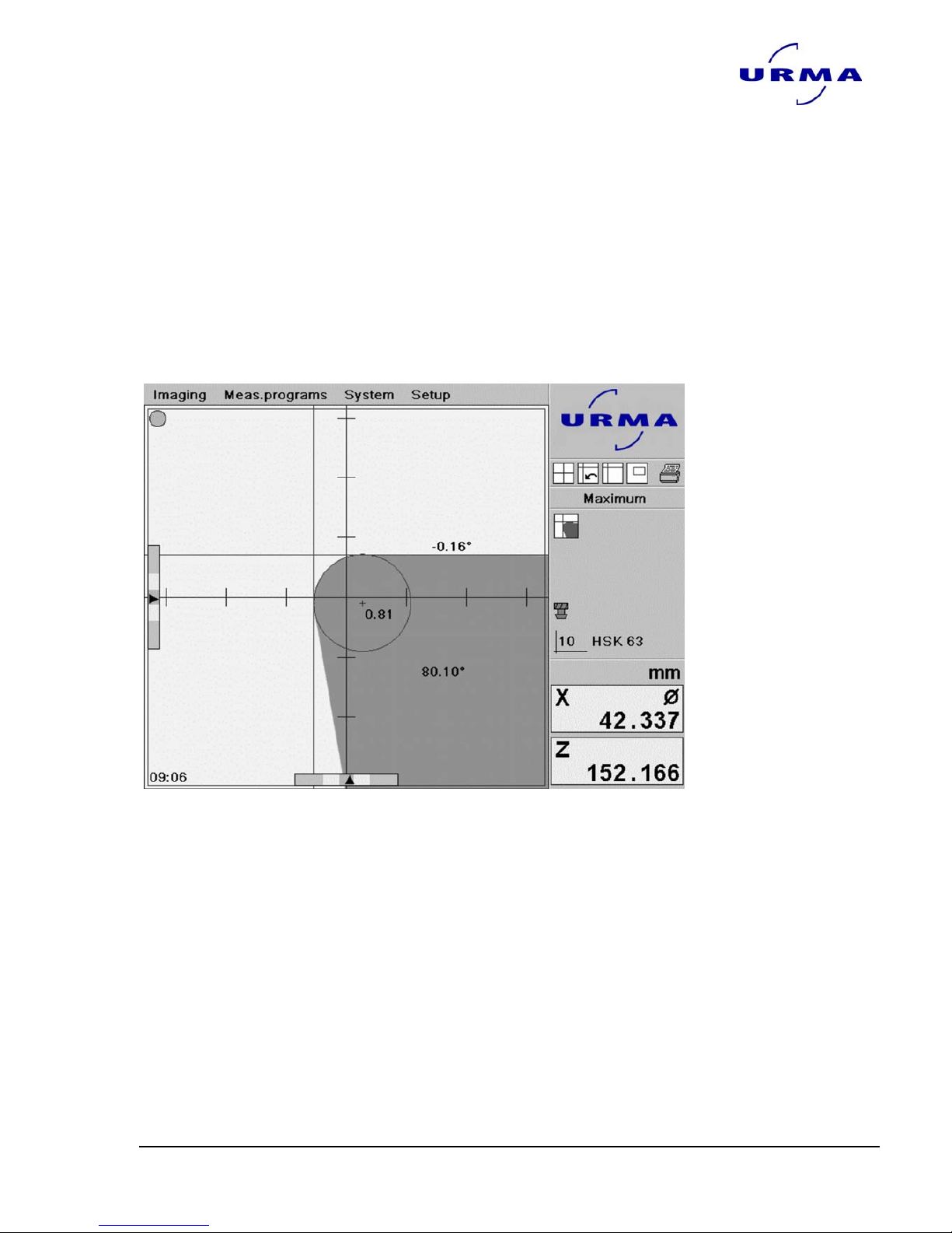
In operational mode the 10.4" colour screen is divided into three sections. The menu
bar is at the top of the screen. Below this, in the largest area of the screen, the live
picture of the object to be measured is displayed with cross hairs and various setting
aids. On the right hand side of the screen a large area with status and system information (status field) extends the whole height of the screen.
Page 19
digiset 5
Urma AG, Switzerland www.urma.ch page 19
5.1.1 Menu bar (Main menu)
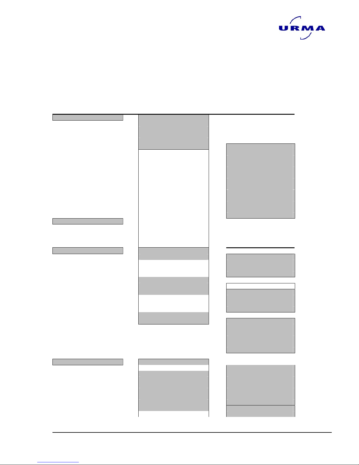
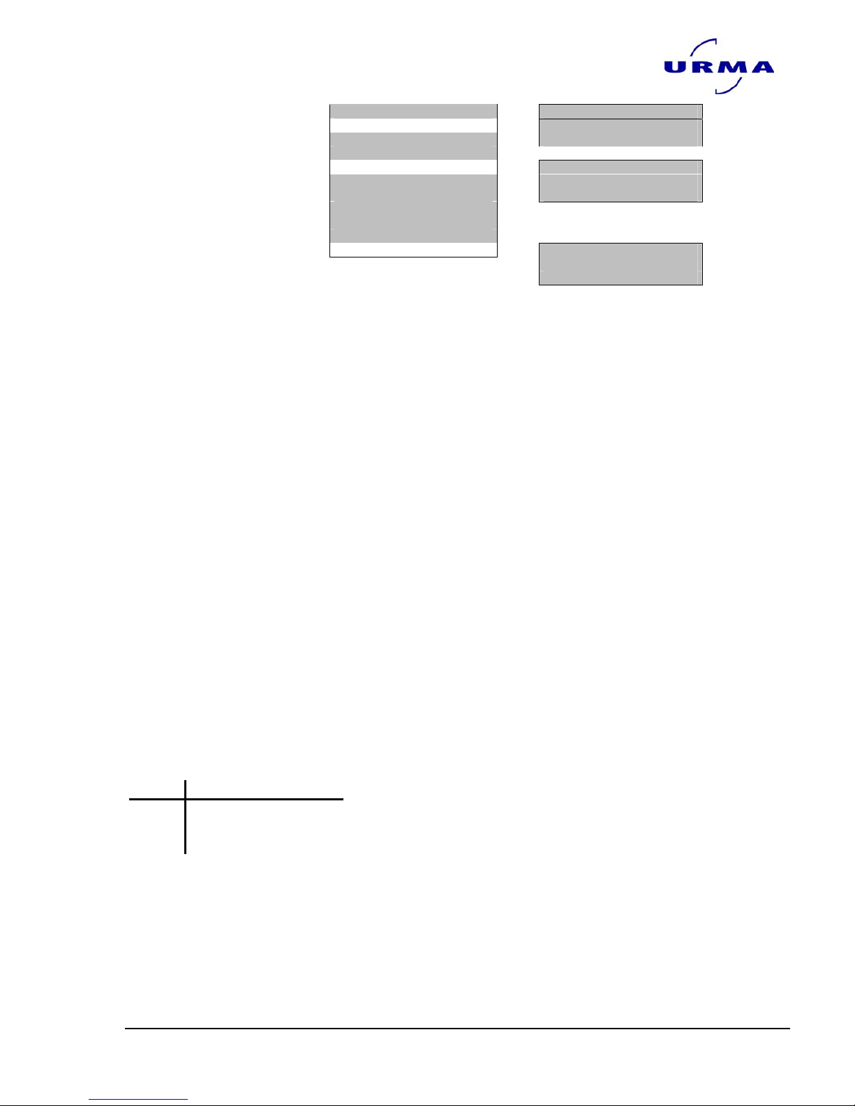
The menu bar represents the Digiset 5 main menu. There are up to two submeus.
Each required operating mode can be selected very quickly by clicking the left mouse
button. If a function contains a further menu (sub-menu), this is shown by an arrow.
ain menu Sub-menu 1 Sub-menu 2
Imaging
Ö
Fixed axis
Maximum
Preset
Measure centre
Range
Measure method
Ö
M0: Automatic
M1: L1
M2: L2
M3: PX
M4: PZ
M5: L1-PX
M6: L2-PX
M7: L1-PZ
M8: L2-PZ
M9: L1-L2
M10: L1-L2-PX
M11: L1-L2-PZ
M12: PX-PZ
Meas. programs
Ö
Line
Angle
Radius
With Measure centre
System
Ö
Select tool reference
Manage tool references
Ö
New
Delete
Change
Show list
Select tool
Deselect tool
Manage tools
Ö
New
Delete
Change
Show list
Tool list
PP-measurement series (1)
Ö
New
Cancel
Interrupt
Continue
Output
Show list
Setup
Ö
Info
Imaging Ö Align camera
Illumination
Coordinate system (1)
Black/White
Brightness (1)
Inverse tool
Parameter
Main menu Sub-menu 1 Sub-menu 2
Interface
Page 20
digiset 5
Urma AG, Switzerland www.urma.ch page 20
Output format
Counter Axis 1
Ö
Axis 2
Corrections Linear correction (1)
Ö
Parallel correction
Absolute zero point (1)
Options
Password
Date and time
Service Factory settings
Ö Delete tool references
Delete tools
5.1.2 Live picture
The object to be measured and the various adjustment aids depending on the operating mode (cross hairs, adjustment bars, test LED, measuring lines, analysis window,
measuring results) are displayed on the live picture operating mode.
5.1.2.1 Cross hairs
The cross hairs give an overview of the position of the contour.
In the "Fixed axis" operating mode the measurements always refer to these cross
hairs with the origin at 0.0 mm or inches. In the "Preset" and "Maximum" operating
modes these cross hairs remain so that the tool reference for the whole measuring
structure is retained. Additional red measuring lines are created on the object’s profile depending on the measuring method determined or selected.
5.1.2.2 Adjustment bars
Adjustment bars are provided for both directions in the "Fixed axis" operating mode.
The pointer in the X adjustment bar gives the contour’s positive or negative deviation
from the measuring line in the X direction, the Z adjustment bar does the same in the
Z direction. The different colours on the bar show the distance of the contour from the
measuring line.
The different setting ranges have the following limits:
Colour Setting range
Grey ± (16 – 60) µm
Yellow ± (4 -15) µm
Green ± (0 -3) µm
5.1.2.3 Test LED
The test LED indicates whether the TCAM2 can correctly apply one of the implemented measurement functions to the object displayed.
Page 21
digiset 5
Urma AG, Switzerland www.urma.ch page 21
• If no measurement functions can be carried out correctly,
the test LED will be red.
Then the data cannot be analysed or further processed by the user.
• If the measurement can be carried out correctly,
the test LED will be green.
5.1.2.4 Measuring lines
The auxiliary lines determined by the TCAM2 using the object to be measured are
marked as measuring lines. They are shown in red.
In the "Fixed axis" operating mode the contour of the object must be aligned to these.
In the "Maximum" and "Preset" operating modes the measuring lines are attached to
the object.
The cross hair axes can also be shown in red as a measuring line
if the selected measuring function requires this, for example for
point measuring with the "Fixed axis" operating mode.
5.1.2.5 Analysis window
The analysis window is displayed as a square edged in red. It marks the area where
the TCAM2 carries out contour measurements so that the most interesting area can
be selected even with objects that have complex contours.
The size of the analysis window can be changed as required. After selecting the
"Range" operating mode, a new analysis window can be created by clicking anywhere in the live picture.
You access this operating mode using the following menu steps:
Main menu Sub-menu 1
Imaging
Ö
Range
When the contour of the object to be measured is clear (line - radius - line) select the whole object field as the analysis window. If
several edges or complex contours are visible, restrict the analysis
window.
5.1.2.6 Measuring results
The measuring results calculated will be displayed on the corresponding position of
the object depending on the measuring programs selected, such as line, angle, radius etc.
If a radius is detected when analysing an object contour, this will be shown as a red
circle and the length of the radius shown in the circle. If the radius on the object contour is smaller than 0.3 mm or larger than 20 mm this value will not be shown.
Page 22
digiset 5
Urma AG, Switzerland www.urma.ch page 22
5.2 Status field
5.2.1 Status and system information
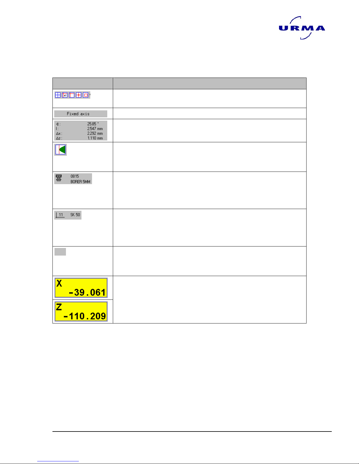
Display Description
Upper toolbar for selecting important operating modes directly
and quickly using tool buttons.
Current operating mode display (status).
Measuring program results display (e.g. line).
Selected measuring method display e.g. M3: PX.
One of the possible measuring methods can be selected after
the contour analysis by clicking on the icon.
Tool icon with the identity number and name of the selected tool
shown in clear text.
The stored tools can be displayed directly by clicking on the tool
icon.
Tool reference symbol with tool reference number and the name
of the tool reference in clear text.
The tool references created can be displayed directly by clicking
on the tool reference icon.
Mm
Display of the selected measuring unit (mm/inch)
You can switch to the other measuring unit by clicking on the
display.
Display of the X and Z readings in absolute display mode if a
counter module is connected.
The hold function for the corresponding axis can be switched on
by clicking on the display fields.
Page 23
digiset 5
Urma AG, Switzerland www.urma.ch page 23
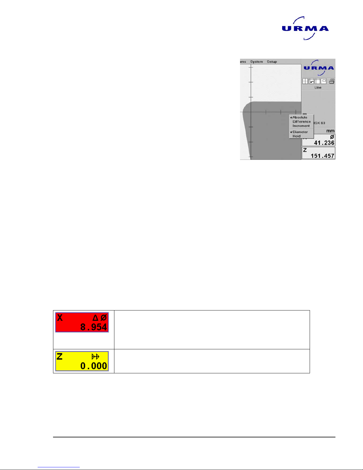
5.2.2 Various methods of displaying readings on the TCAM2
You access this operating mode using the right
bottom of the mouse. You position the cursor
either in the counter field of X or Z-axis and press
the eight bottom on the mouse.
The window with the methods of displaying will
Open.
You can change the attributes for each axis separately.
• Absolute
Current counter value relating to the selected tool reference.
• Difference
Current counter value relating to the selected tool reference including nominal values.
• Increment
The reading is reset to 0.000.
• Diameter
The current reading is doubled.
• Hold
The hold function (counter stop function) is switched on.
The counter analysis continues to work in the background.
As the following examples show, the different display modes can be shown combined
with each other:
Display of the X reading with additional information
∆ Difference display
∅ Diameter display
red Display with hold function set (counter stop).
Display of the Z reading in increment mode.
Page 24
digiset 5
Urma AG, Switzerland www.urma.ch page 24
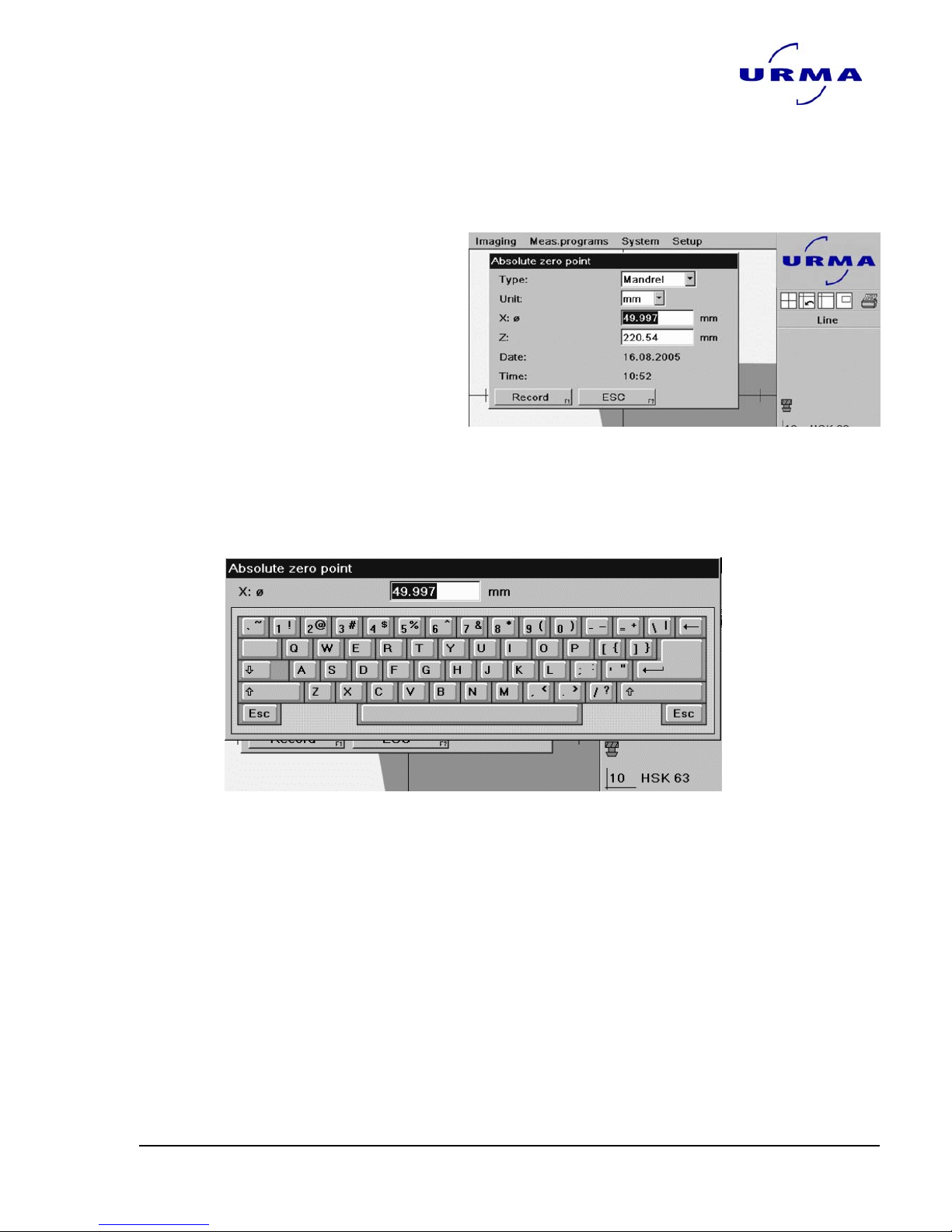
5.3 Input by keyboard
The TCAM2 has no keyboard . If you have to enter alphanumerical strings in
An entering field, than you have to position the cursor on this field and you press
The right bottom of your mouse.
Example set absolute zero point
When the cursor is set to the field
X ( white digits in a blue field)
You press the right bottom on your
Mouse
It will open a window with the keyboard
With the cursor you can now klick on the bottoms of the keyboard and in this way
enter the alphanumerical strings.
When you press ENTER the string will be written to the entering field and the keyboard will be closed.
Page 25
digiset 5
Urma AG, Switzerland www.urma.ch page 25
6 Configuration (software setup)
6.1 Info
You access this operating mode using the following menu steps:
Main menu Sub-menu 1
Setup
Ö
Info
The info window gives you the current system information and you can license software extensions that need to be paid for by entering a new licence number.
Make sure you don’t lose the licence number!
If you lose the licence number the system can no longer be operated. In this case, please contact the manufacturer on
+41-62-889 2020 or [email protected]
If you buy a software update, you will receive a new licence number with the software
extension that must be entered.
Page 26
digiset 5
Urma AG, Switzerland www.urma.ch page 26
6.2 Imaging
6.2.1 Coordinate system (optional)
The names of the vertical and horizontal axes often vary with measuring instruments.
And so vertical and horizontal adjustment devices also differ in their axis assignment
for example.
This operating mode is therefore used for the axis assignment (X = horizontal or vertical, Z = vertical or horizontal) including the imaging axes with the counter module
axes.
You access this operating mode using the following menu steps:
Main menu Sub-menu 1 Sub-menu 2
Setup
Ö
Imaging
Ö
Coordinate system
6.2.2 Black/White
You access this operating mode using the following menu steps:
Main menu Sub-menu 1 Sub-menu 2
Setup
Ö
Imaging
Ö
Black/White
Here you can decide whether an object and its contour are displayed in colour (false
colours) or in black and white (grey scale).
The standard setting with false colours is used for the transmitted light application.
It gives optimum optical contrast for your observations and is the basis for precise
measuring results.
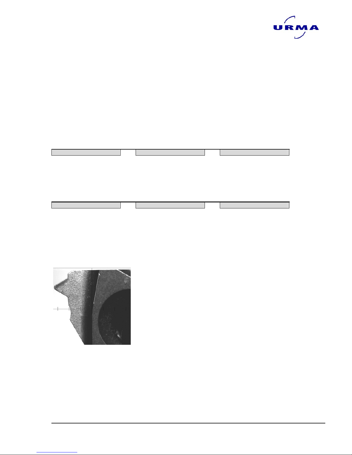
Incident applications, such as cutting inspections,
are carried out in the Black/White setting because
with this the user can check the surface of the object
visually very easily for any damage.
You can use the "Line" and "Radius" measurement
function to analyse edges on the surface of an object
very well geometrically.
Tool cutting edge in incident light
Page 27
digiset 5
Urma AG, Switzerland www.urma.ch page 27
6.2.3 Brightness (optional)
In the "Black/White" operating mode the "Brightness" function is used to adjust the
brightness of the live picture.
You access this operating mode using the following menu steps:
Main menu Sub-menu 1 Sub-menu 2
Setup
Ö
Imaging
Ö
Brightness
You also can start the "Brightness" function by right clicking (context menu) when the mouse pointer is placed on the live picture.
6.2.4 Inverse tool
You access this operating mode using the following menu steps:
Main menu Sub-menu 1 Sub-menu 2
Setup
Ö
Imaging
Ö
Inverse tool
This menu item works as a toggle function and changes the setting of a normal tool
with cuts outwards to an "inverse tool" with cuts inwards, such as is the case with bell
tools. The "Inverse tool" setting only works with the "Maximum" measuring method.
6.2.5 Imaging parameters
You access this operating mode using the following menu steps:
Main menu Sub-menu 1 Sub-menu 2
Setup
Ö
Imaging
Ö
Parameter
The following parameters can be set using the rough setting slider.
• Line length
• Line deviation
• Radius deviation
The object to be measured must be moved until it is in camera
range.
6.2.5.1 Line length
You use line length to set how long a line must be before it is detected by TCAM2 as
a line.
The sensitivity can be varied from 0.000 mm to 3,000 mm.
The standard setting (default) is 1,020 mm.
Page 28
digiset 5
Urma AG, Switzerland www.urma.ch page 28
6.2.5.2 Line deviation
The line deviation parameter gives the maximum permissible deviation of the edge
values from the ideal shape of the line.
The deviation can be varied from 0 µm to 100 µm.
The standard setting (default) is 20 µm.
6.2.5.3 Radius deviation
The radius deviation parameter gives the maximum permissible deviation of the edge
values from the ideal shape of the circle.
The deviation can be varied from 0 µm to 100 µm.
The standard setting (default) is 45 µm.
6.3 Serial interface (counter module)
You access this operating mode using the following menu steps:
Main menu Sub-menu 1
Setup
Ö
Interface
Here you can configure the counter module’s serial interface for data output.
The serial interface on Digiset 5 is only meant for data transfer between the TCAM2 and the counter module.
It cannot be configured.
Page 29
digiset 5
Urma AG, Switzerland www.urma.ch page 29
6.4 Output format
You access this operating mode using the following menu steps:
Main menu Sub-menu 1
Setup
Ö
Output format
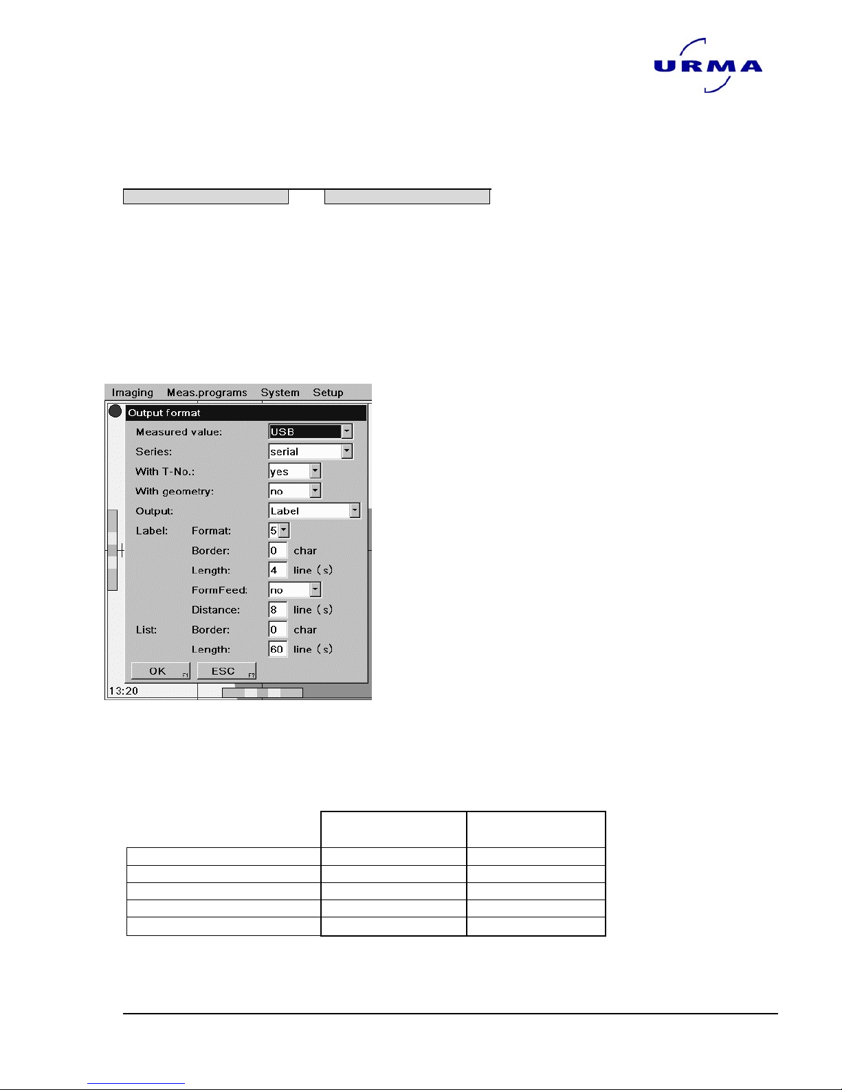
Here you define the interface for an output and the corresponding formats for labels
or lists.
For labels the required format can also be selected from a format template catalogue.
Digiset 5 has a serial interface and a standard a USB port.
In this window you define the interface for
an output and the corresponding formats for
labels or lists.
For labels the required format can also be
selected from a format template catalogue.
The USB port is available as a special fitting in addition to the serial and parallel
ports.
Measured value:
Output of the measured values of
one tool
Series:
Output of a list of measured values
of dif ferent tools format template catalogue
For the two printers of our product program you will find the format template in the
following list.
Seikosha SP 2400 DYMO 310
Matrixprinter Thermoprinter
Label Format 5 3
Border 1 0
Length 4 5
Form Feed No yes
Distance 8 0
Page 30
digiset 5
Urma AG, Switzerland www.urma.ch page 30
6.5 Measuring systems
It is possible to configure all signal inputs separately.
The third axis (Axis 3) is optionally.
You access these operating modes using the following menu steps:
Main menu Sub-menu 1 Sub-menu 2
Setup
Ö
Counter
Ö
Axis 1
Axis 2
Axis 3
Parameters that must be entered to configure a measuring system entry in the fields
provided for it depend on the measuring systems connected.
Page 31
digiset 5
Urma AG, Switzerland www.urma.ch page 31
6.6 Corrections
6.6.1 Linear correction (optional)
You access this operating mode using the following menu steps:
Main menu Sub-menu 1 Sub-menu 2
Setup
Ö
Corrections
Ö
Linear correction
Correction values can be calculated in the "Linear correction" operating mode using
target and actual value comparisons and then automatically taken into consideration
in every measurement.
This correction value is calculated using end measurements (=nominal value).
Each axis can be given a correction value.
6.6.2 Parallel correction
You access this operating mode using the following menu steps:
Main menu Sub-menu 1 Sub-menu 2
Setup
Ö
Corrections
Ö
Parallel correction
The axis of the calculated correction values is automatically allocated by the system
with parallel correction.
6.6.3 Absolute zero point (optional)
You access this operating mode using the following menu steps:
Main menu Sub-menu 1 Sub-menu 2
Setup
Ö
Corrections
Ö
Absolute zero point
The absolute zero point is the reference point for all stored tool references.
For this reason, before saving tool references, it is necessary to store the absolute
zero point as follows.
Procedure:
Select the "Absolute zero point" operating mode.
1. Enter the known dimensions of the setting pin.
2. Move the two measuring points in X and Z in any order and confirm the relevant positions by pressing the <Record > key.
3. After accepting the two measuring points the TCAM2 is in the "Measure centre" operating mode with 0 as the tool reference so that the measurement on
the calibration pin and thus the correct recording of the absolute zero point
can be checked.
The order of recording the measuring point doesn’t matter because Digiset 5 carries out the allocation by itself.
)
Page 32
digiset 5
Urma AG, Switzerland www.urma.ch page 32
6.7 Options
This operating mode gives you the option of setting specific system settings so that
they are automatically selected even after the system is restarted.
You access this operating mode using the following menu steps:
Main menu Sub-menu 1
Setup
Ö
Options
• Angle:
Selecting/ deselecting the display of one or more angle values in the TCAM2 live picture.
• Circle:
Selecting/ deselecting the display of a circle and the corresponding radius value in the TCAM2 live picture.
If this is selected any available radius on an object contour is
shown as a circle in the object image.
• Measure method:
Selecting a standard measuring method. This is activated
when starting the TCAM2.
• Language:
Selecting one of the loaded language modules.
6.8 Password
Important system settings can be protected from unauthorised access by allocating a
password.
You access this operating mode using the following menu steps:
Main menu Sub-menu 1
Setup
Ö
Password
A password can be allocated or changed. You must enter the password a second
time to confirm the first entry.
The following options are available for entering a password:
• none
It is not necessary to enter a password when selecting a protected
operating mode (factory setting).
• once
It is necessary to enter the password when selecting a protected operating mode for the first time. It is not necessary to enter the password again if you select the protected operating modes again because the password is stored until the unit is switched off.
• always
It is necessary to enter the password every time you select a protected operating mode.
The password can be entered alphanumerically. You can enter up
to 6 characters.
Page 33
digiset 5
Urma AG, Switzerland www.urma.ch page 33
6.9 Date and time (optional)
Requirement for this operating mode is the clock module (hardware option), then
time indication on the live picture is possible.
Additional possibilities:
• Storing of date and time when entering tool references and corrections.
• Documentation of date and time on measuring output report.
You access this operating mode using the following menu steps:
Main menu Sub-menu 1
Setup
Ö
Date and time
6.10 Maintenance and service
To maintain the system it is sometimes necessary to load the factory settings (default
values) and to delete the tool reference memory or the tool memory completely.
You access the corresponding operating modes using the following menu steps:
Main menu Sub-menu 1 Sub-menu 2
Setup
Ö
Service
Ö
Factory settings
Delete tool references
Delete tool data
The 0 tool reference is not deleted when deleting the tool reference memory.
Page 34
digiset 5
Urma AG, Switzerland www.urma.ch page 34
7 System
7.1 Tool references
The 0 (zero) tool reference is fixed.
Furthermore, the system gives you the option of saving and managing up to 99 more
tool references.
7.1.1 Select tool references
You access this operating mode using the following menu steps:
Main menu Sub-menu 1
System
Ö
Select tool reference
The corresponding tool reference number must be entered and confirmed to select
the required tool reference.
7.1.2 Manage tool references
This menu item gives you the option of creating and saving new tool references,
changing and deleting stored tool references and displaying a list of all tool references.
Before a new tool reference is saved the absolute zero point must
be saved.
You access this operating mode using the following menu steps:
Main menu Sub-menu 1 Sub-menu 2
System
Ö
Manage tool references
Ö
New
Delete
Change
Show list
7.1.2.1 Create new tool references
After selecting the "New" operating mode, a window opens with input fields underlined in white.
After the final confirmation the new tool reference is saved.
Page 35
digiset 5
Urma AG, Switzerland www.urma.ch page 35
7.1.2.2 Delete tool references
After selecting the "Delete" operating mode the corresponding tool reference must be
selected in the selection window.
There is an additional security query before the tool reference can be deleted after it
is confirmed.
The 0 tool reference cannot be deleted.
7.1.2.3 Change tool references
After selecting the "Change" operating mode the corresponding tool reference must
be selected once more in the selection window.
After confirming that you have found the correct tool reference, a window in which
changes can be made opens as it does when entering a new tool reference.
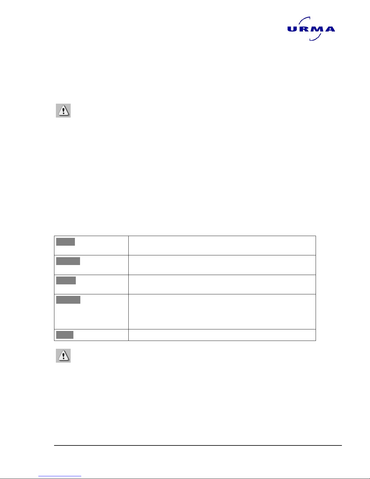
7.1.2.4 Show tool reference list
After selecting the "Show list" operating mode, a window opens with a selection list of
the saved tool references and the buttons explained below:
Select The tool reference highlighted in the selection list will be lo-
aded.
Change The tool reference highlighted in the selection list can be
changed.
Delete The tool reference highlighted in the selection list is deleted
after it has been confirmed with the security query.
Print list The tool references will be printed giving the tool reference
number and the tool reference name in table form using the
interface defined in the "Output format / Measured value"
menu item.
Close The tool reference list is closed.
The 0 tool reference cannot be edited and will therefore not be
displayed in the tool reference list.
Page 36
digiset 5
Urma AG, Switzerland www.urma.ch page 36
7.2 Tools
The system offers you the opportunity to save and manage up to 1000 tools.
7.2.1 Select tool
You access this operating mode using the following menu steps:
Main menu Sub-menu 1
System
Ö
Select tool
The corresponding tool identity number (tool ID) must be entered and confirmed to
select the required tool.
7.2.2 Manage tools
This menu item gives you the option of creating and saving new tools, changing and
deleting stored tools and displaying a list of all tools.
You access this operating mode using the following menu steps:
Main menu Sub-menu 1 Sub-menu 2
System
Ö
Manage tools
Ö
New
Delete
Change
Show list
7.2.2.1 Create new tool
After selecting the "New" operating mode, a window opens with input fields underlined in white.
After the final confirmation the new tool is saved.
Using the playback function the current readings are copied to the input screen as
nominal values.
Page 37
digiset 5
Urma AG, Switzerland www.urma.ch page 37
7.2.2.2 Delete tool
After selecting the "Delete" operating mode the corresponding tool must be selected
in the selection window.
There is an additional security query before the tool can be deleted after it is confirmed.
7.2.2.3 Change tool
After selecting the "Change" operating mode the corresponding tool must once more
be selected in the selection window.
After confirming that the correct tool has been selected, a window in which the changes can be made opens, just as it does when entering a new tool.
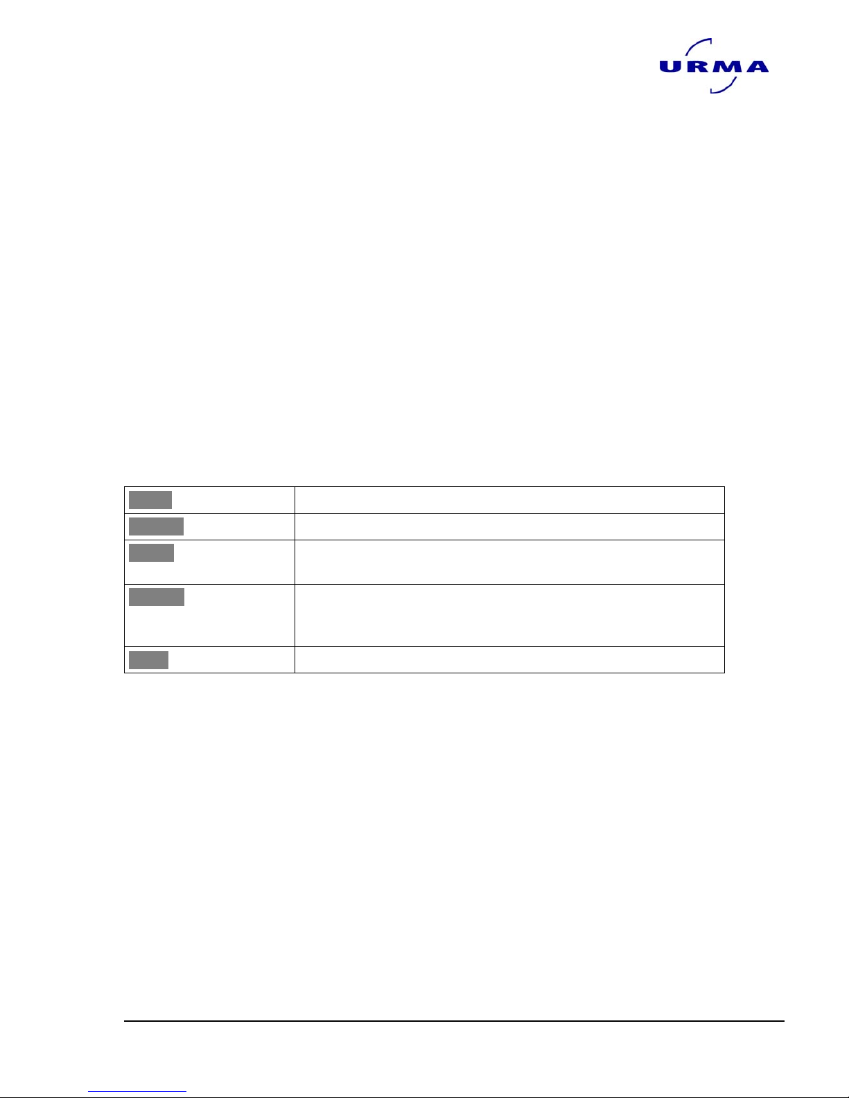
7.2.2.4 Show list of tools
After selecting the "Show list" operating mode, a window opens with a selection list of
the saved tools and the buttons explained below:
Select The tool highlighted in the selection list will be loaded.
Change The tool highlighted in the selection list can be changed.
Delete The tool highlighted in the selection list is deleted after it has
been confirmed with the security query.
Print list The tools will be printed giving the tool ID and tool name in
table form using the interface defined in the "Output format /
Measured value" menu item.
Close The list of tools is closed.
Page 38
digiset 5
Urma AG, Switzerland www.urma.ch page 38
7.3 Tool list
You access this operating mode using the following menu steps:
Main menu Sub-menu 1
System
Ö
Tool list
After selecting this operating mode the measured tools are listed in a window as a
table with a consecutive number, information on the tool reference, the T number
(tool number) and the tool name. In addition the buttons shown have the following
functions:
Edit The entries on the tool selected in the tool list can be chan-
ged.
New The tool selected in the tool list will be measured again.
Delete The tool marked in the selection list is deleted after it has
been confirmed with the security query.
Print list The tool list will be printed using the interface defined in the
"Output format / Series" menu item after a list number has
been allocated in another window.
Delete all The whole tool list will be deleted after the security query
has been confirmed.
Close The tool list is closed.
Page 39
digiset 5
Urma AG, Switzerland www.urma.ch page 39
7.4 Post processor-measurement series (optional)
You access this operating mode using the following menu steps:
Main menu Sub-menu 1 Sub-menu 2
System
Ö
PP-measurement series
Ö
New
Cancel
Interrupt
Continue
Output
Show list
7.4.1 New
This operating mode is used to create a measurement range which can be transferred as a controlled output format to a machine. Such a range of measurements
can consist of a maximum of 50 data records.
Procedure:
1. Under the "New" operating mode select the required output format from a list
of no more than five stored formats (post processor formats).
2. After selecting the desired output format, the corresponding input mask
opens. Enter the logarithm data here. This input mask doesn't have to appear in any case. It depends on the selected post processor.
3. In order to store the measured values for X and Z in a data record, click on
the print symbol in the status window.
4. A further input mask opens in which the measured values for X and Z are already entered. Enter any additional PP specific parameters here.
5. Only then can the data record be stored and the measured values printed.
Only one measurement range can be stored.
7.4.2 Cancel
The PP measurement range is cancelled. All data records which have been stored so
far in the measurement range are deleted.
)
Page 40
digiset 5
Urma AG, Switzerland www.urma.ch page 40
7.4.3 Interrupt
Storing further data records in the PP measurement range is interrupted. All data records which have been stored so far in the measurement range are retained.
7.4.4 Continue
The interrupted and stored measurement range continues and further data records
are added.
7.4.5 Output
The measurement range is transferred as a controlled output format to a machine
tool. Either the serial interface (RS232) or the Ethernet effects the transfer.
If several machine tools are connected to an TCAM2 plus and you
decide to transfer your data via an RS232, you need an external
interface converter.
If you are using the Ethernet you must enter the IP address of the
corresponding machine in the TCAM2 plus.
7.4.6 Show list
You see a list with all the data that has been stored up till now.
Page 41
digiset 5
Urma AG, Switzerland www.urma.ch page 41
8 Imaging
For each measuring procedure ensure that the edges of the object to be
measured are not dirty because this could lead to incorrect measuring results.
8.1 Starting imaging
After it is switched on the Digiset 5 runs in accordance with the settings made in Options.
The object to be measured must be moved until it is in camera range and the contour
of the object, e.g. the tool cutting edge must be focussed sharply by turning the tool
on the tool support.
Procedure:
1. Move the object into the camera’s visual range.
2. If the relevant contour of the object is not clear, select the "Range" operating
mode and, using the mouse, make it the required size and drag it round the
relevant edge.
3. Turning the object to be measured on its support sets the greatest deviation
and thus the focus level.
4. While the object is being turned the test LED in the upper left corner turns
green as soon as the measurement is correct, i.e. the greatest deviation has
been determined. You must ensure here that the turning speed is not too
great.
It is vital here that the camera’s working distance has been set
correctly when commissioning the system (focussing).
If a counter module is connected the system waits for the reference marks of the
connected measuring systems to be transferred. The readings taken will be displayed directly after the reference trip.
8.1.1 Camera 2 (optional)
You access this operating mode using the following menu steps:
Main menu Sub-menu 1
Imaging
Ö
2. Camera
If a second camera (e.g. incident camera) is used in the imaging system and both
cameras are attached to the TCAM2 via a camera switchbox, you can switch over to
the other camera using this operating mode.
)
Page 42
digiset 5
Urma AG, Switzerland www.urma.ch page 42
8.2 Measuring methods
8.2.1 Fixed axis
Here all measurements relate to the original cross hair co-ordinates.
You access this operating mode using the following menu steps:
Main menu Sub-menu 1
Imaging
Ö
Fixed axis
After selection the system analyses the object contour and automatically suggests a
measuring procedure for carrying out measurements immediately. The measuring
procedure used is displayed in the status window at the same time. If an alternative
measuring procedure is required it is possible to enter the measuring procedure manually by pressing the button in the status window.
Procedure:
6. Move the object into the camera’s visual range.
7. Roughly set the picture focus by turning the object on its support to its
maximum deviation.
8. As soon as the object to be measured is within the focussing area, the adjustment bars are displayed. The TCAM2 automatically determines the best
measuring procedure and the test LED goes green.
9. Move the edge of the object as close as possible to the cross hairs so that
the arrow of the adjustment bar corresponding to the deviation direction is in
the green area.
10. The focus is finely adjusted by once again turning the object in the direction
of the focus level until the arrow shows the maximum deviation in the corresponding adjustment bar.
11. If the TCAM2 does not set the measuring procedure or the analysis window
to your requirements, change this manually.
The analysis window should always be around the co-ordinate origin point.
12. Align the contour on the measuring lines. Note the adjustment bars that give
you optimum support for this.
13. If the adjustment bar pointers are in the middle you have found the best
possible position for the object. You can now further process the data and
start measuring again.
)
Page 43
digiset 5
Urma AG, Switzerland www.urma.ch page 43
8.2.2 Maximum
The measuring lines are created on the contour of the object to be measured. Both
adjustment bars are hidden. The offset of the measuring lines and the fixed cross
hairs in the X and Z direction is taken into account with the current position.
You access this operating mode using the following menu steps:
Main menu Sub-menu 1
Imaging
Ö
Maximum
After selection the system analyses the object contour and automatically suggests a
measuring procedure for carrying out the measurements immediately. The measuring
procedure used is displayed in the status window at the same time. If an alternative
measuring method is required it is possible to enter the measuring procedure manually by pressing the button.
Procedure:
1. Move the object into the camera’s visual range.
2. If the relevant contour of the object is not clear, select the "Range" operating
mode and, using the mouse, make it the required size and drag it round the
relevant edge.
3. Select the operating mode as described above.
4. Turning the object to be measured on its support sets the greatest deviation.
5. While the object is being turned the test LED turns green as soon as the
measurement is correct, i.e. the greatest deviation has been determined.
You must ensure here that the turning speed is not too great. When the
measurement has been made correctly the offset values are saved and
transferred through the serial port.
6. If the object is set to a specific size, the object must be moved again to the
greatest deviation position so that the arrow of the adjustment bar corresponding to the deviation direction is in the green area again.
7. Then the unit switches to the "Preset" measuring method.
)
Page 44
digiset 5
Urma AG, Switzerland www.urma.ch page 44
8.2.3 Preset
The measuring lines are created on the contour of the object to be measured. Both
adjustment bars are hidden. The offset of the measuring lines and the fixed cross
hairs in the X and Z direction is taken into account with the current position.
You access this operating mode using the following menu steps:
Main menu Sub-menu 1
Imaging
Ö
Preset
After selection the system analyses the object contour and automatically suggests a
measuring procedure for carrying out the measurements immediately. The measuring
procedure used is displayed in the status window at the same time. If an alternative
measuring method is required it is possible to enter the measuring procedure manually by pressing the button.
Procedure:
1. Move the object into the camera’s visual range.
2. If the relevant contour of the object is not clear, select the "Range" operating
mode and, using the mouse, make it the required size and drag it round the
relevant edge.
3. Select the operating mode as described above.
4. Digiset 5 automatically determines the best measuring procedure and the
test LED goes green. Depending on the measuring procedure selected
measuring lines are created on the object’s contour.
5. The object to be measured can now be set to the required size taking note
of the reading.
6. If the TCAM2 does not set the measuring procedure to your requirements,
change this manually.
The object to be measured must be in the camera’s focussing
area.
)
Page 45
digiset 5
Urma AG, Switzerland www.urma.ch page 45
8.2.4 Measure centre
Here the TCAM2 determines the edge pixel next to the cross hair origin point. This is
done using the pointers in the adjustment bars that should, ideally, both be in the
middle. The edge point is next to the cross hair origin point when both pointers are in
the middle of the green area.
You access this operating mode using the following menu steps:
Main menu Sub-menu 1
Imaging
Ö
Measure centre
Selecting this measuring method is recommended when carrying out the following
setup settings because any dust and dirt residue on the object to be measured, e.g.
gauge (calibrating mandrel or ball gauge), will not affect the measuring results.
• Parallel correction
• Absolute zero point
Page 46

digiset 5
Urma AG, Switzerland www.urma.ch page 46
8.3 Measuring procedures
8.3.1 Principal procedures in contour analysis
Digiset 5 has two main measuring procedures that are used for analysing an object
contour.
• Point measurement
• Line or angle measurement
8.3.1.1 Point measurement
Point measurement determines the highest deviation value in the corresponding axis.
This is done in the "Fixed axis" measuring method by moving the object to be measured to the corresponding cross hairs axis so that the adjustment bar pointer is in the
green area.
In the "Maximum" and "Preset" measuring methods Digiset 5 automatically calculates
the highest deviation position and creates the red measuring lines vertically or horizontally.
8.3.1.2 Line or angle measurement
Line measurement determines and analyses one or more of the object’s straight contour sections.
In the "Fixed axis" measuring method, red lines which pass through the cross hairs
origin point are drawn parallel to these contour sections and their angles to the cross
hairs displayed. The distance of the object to be measured from the red measuring
line(s) is indicated by the adjustment bar pointers.
In the "Maximum" and "Preset" measuring methods the red measuring lines are
placed directly above the object’s straight contour sections. The imaging results and
the current position of the optical equipment carrier are taken into account together.
Page 47
digiset 5
Urma AG, Switzerland www.urma.ch page 47
8.3.2 Detailed description of measuring procedures
12 detailed measuring procedures have been developed from the main measuring
procedures. Digiset 5 uses these to analyse contours.
The number of different measuring possibilities is, of course, significantly higher because the measuring procedure can be carried out in each individual quadrant.
You access this operating mode using the following menu steps:
Main menu Sub-menu 1 Sub-menu 2
Imaging
Ö
Measure method
Ö
M0: Automatic
M1: L1
M2: L2
M3: PX
M4: PZ
M5: L1-PX
M6: L2-PX
M7: L1-PZ
M8: L2-PZ
M9: L1-L2
M10: L1-L2-PX
M11: L1-L2-PZ
M12: PX-PZ
Procedure Brief explanation
• M0: Automatic
The procedure used is determined by the TCAM2
• M1: L1
Line 1 measurement
• M2: L2
Line 2 measurement
• M3: PX
Point X measurement
• M4: PZ
Point Z measurement
• M5: L1-PX
Line 1 and point X measurement
• M6: L2-PX
Line 2 and point X measurement
• M7: L1-PZ
Line 1 and point Z measurement
• M8: L2-PZ
Line 2 and point Z measurement
• M9: L1-L2
Line 1 and line 2 measurement
• M10: L1-L2-PX
Line 1 and line 2 and point X measurement
• M11: L1-L2-PZ
Line 1 and line 2 and point Z measurement
• M12: PX-PZ
Point X and point Z measurement
When fixing the line and angle markings light/dark borders are
seen going counter-clockwise from the positive X axis. Line 1 is
shown as the light to dark border within the analysis window. Line
2 is set as the dark to light border.
If Digiset 5 cannot use any of the measuring procedures for the
contour detected, the test LED in the upper left corner of the
screen will be red. The measuring results are then incorrect! .
Page 48
digiset 5
Urma AG, Switzerland www.urma.ch page 48
8.3.2.1 "Line 1" measurement (L1)
Line 1 is determined.
(Light to dark border counter clockwise within the analysis window)
8.3.2.2 "Line 2" measurement (L2)
Line 2 is determined.
(Dark to light border counter clockwise within the analysis window)
8.3.2.3 "Point X" measurement (PX)
The maximum X deviation is determined.
8.3.2.4 "Point Z" measurement (PZ)
The maximum Z deviation is determined.
Linie 1
Linie 2
Punkt X
Punkt Z
Page 49
digiset 5
Urma AG, Switzerland www.urma.ch page 49
8.3.2.5 "Line 1 - Point X" measurement (L1 - PX)
The vertical axis is touched at one point and shown as a red
measuring line. Line 1 runs through the cross hairs origin point.
The contour is aligned to its optimum level when the pointers on
both adjustment bars are exactly in the middle.
8.3.2.6 "Line 2 - Point X" measurement (L2 - PX)
The maximum X deviation and line 2 are determined. The results then show the intersection point.
8.3.2.7 "Line 1 - Point Z" measurement (L1 - PZ)
The maximum Z deviation and line 1 are determined. The results then show the intersection point.
8.3.2.8 "Line 2 - Point Z" measurement (L2 - PZ)
The horizontal axis is touched at one point and shown as a red
measuring line. Line 2 runs through the cross hairs origin point.
The contour is aligned to its optimum level when the pointers on
both adjustment bars are exactly in the middle.
Punkt X
Linie 1
Linie 2 Punkt X
Punkt Z
Linie 1
Linie 2
Punkt Z
Page 50
digiset 5
Urma AG, Switzerland www.urma.ch page 50
8.3.2.9 "Line 1 -Line 2" measurement (L1 - L2)
The intersection point of both measuring lines (line 1 and line 2)
is determined.
8.3.2.10 "Line 1 - Line 2 - Point X" measurement (L1 - L2 - PX)
The vertical axis is touched at one point and shown as a red
measuring line. The intersection point of the two other measuring lines is on the horizontal axis.
The contour is aligned to its optimum level when the pointers on
both adjustment bars are exactly in the middle.
8.3.2.11 "Line 1 - Line 2 - Point Z" measurement (L1 - L2 - PZ)
The horizontal axis is touched at one point and shown as a red
measuring line. The intersection point of the two other measuring lines is on the vertical axis.
The contour is aligned to its optimum level when the pointers on
both adjustment bars are exactly in the middle.
8.3.2.12 "Point X - Point Z" measurement (P1 - PZ)
The horizontal and vertical axes are touched at one point and
shown as red measuring lines.
The contour is aligned to its optimum level when the pointers on
both adjustment bars are exactly in the middle.
Linie 2
Linie 1
Linie 1
Punkt X
Linie 2
Linie 1
Punkt Z
Linie 2
Punkt X
Punkt Z
Page 51
digiset 5
Urma AG, Switzerland www.urma.ch page 51
8.4 Measuring programs / Measuring functions
You access this operating mode with the "Measuring programs" menu item in the
main menu:
Main menu Sub-menu 1
Meas. Programs
Ö
Line
Angle
Radius
With measure centre
These measuring functions must be used regardless of the possible settings in
"Measure method".
8.4.1 Line
The "Line" measurement function is used to measure a line visually from point to
point. If the TCAM2 finds an edge near the selected point, the next edge pixel will be
taken as the display and analysis point. If there is no edge nearby, the precise position of the mouse pointer will be taken.
Procedure:
1. Select "Line".
2. Move the mouse pointer to the desired position and left click. The TCAM2
sets the first analysis point on the next edge pixel.
3. Move the mouse pointer to the next position and left click. The TCAM2 sets
the second analysis point on the next edge pixel. The function is now closed
and angle, length and the orthogonal ∆x and ∆z difference of the line are
displayed in the status window.
The first analysis point is the origin point for calculating the angle
while the second analysis point marks the end of the line whose
angle is calculated on the horizontal axis.
)
Page 52
digiset 5
Urma AG, Switzerland www.urma.ch page 52
8.4.2 Angle
The "Angle" measurement function is used to measure visually the angle between
two lines. Here too the next edge pixel is taken as the display and analysis point.
Procedure:
1. Select "Angle".
2. Move the mouse pointer to the required position and by clicking on two
points on each line, mark the two lines where the angle is to be determined.
3. By clicking on the last point the angle is calculated and displayed in the
status window together with the intersection point co-ordinates, x0 and z0,
for both lines.
4. Complementary or corresponding angles can be displayed using the <F6>
key.
8.4.3 Radius
The "Radius" measurement function is used to measure visually a circle or radius
from 3 points. Here too the TCAM2 looks for the next edge pixel as an analysis point.
Procedure:
1. Select "Radius".
2. Move the mouse pointer to the desired position and left click. The TCAM2
sets the first analysis point here.
3. Move the mouse pointer to the desired position and left click. The TCAM2
sets the second analysis point here.
4. Move the mouse pointer to the desired position and left click. The TCAM2
sets the third analysis point here and draws the circle calculated directly.
The radius and the x and z co-ordinates of the centre of the circle (x0, z0)
can be seen in the status window.
By moving the optical equipment carrier along an object contour it
is possible to measure larger radii too.
8.4.4 With measure centre
In the line, angle, radius, perpendicular measurement programs etc. the measuring
points are marked by default with the mouse pointer. The "With measure centre" operating mode enables you to define these measuring points with the original cross
hair co-ordinates.
)
)
Page 53

digiset 5
Urma AG, Switzerland www.urma.ch page 53
9 Index
Adjustment bars 20
Analysis window 21
Auxiliary line 21
Baud rate 28
Brightness 27
Circle detection 28
Cross hairs 20
Cutting inspection 26
Data transfer 39
Date 33
Default values 33, 54
Delivery schedule 5
Display circles 32
EMC 8
Illumination lines 13
Incident camera 41
Installation
Camera 12, 15
Illumination 13
Line detection 27
Live picture 20
Maintenance 33
Manufacturer’s declaration 8
Measurement
correct 20
incorrect 20, 47
Measuring function
Angle 52
Line 51
Radius 52
With measure centre 52
Measuring line 21
Measuring method
Fixed axis 42
Maximum 43
Measure centre 45
Preset 44
Measuring procedure
Description of principal procedures 46
Detailed description 47
Line measurement 46
Point measurement 46
Measuring results 21
Measuring systems 30
Axis assignment 26
Menu control 19
Object display 26
Parameter
Line deviation 28
Line length 27
Radius deviation 28
Parameters 27
Password 32, 54
Post processor 39
Radius display 21
Serial interface 28
Service line 5
Status field 22
System information 25
Time 33
Tool 36
Change 37
Delete 37
New 36
Select 36, 37
Show list 37
Tool reference 34
Change 35
Delete 35
New 34
Selection 34
Show list 35
Transfer rate 28
Page 54

digiset 5
Urma AG, Switzerland www.urma.ch page 54
10 Appendix 1 / Password
111111
Password/ Factory setting
 Loading...