

URC ZR-1N Owner's Manual
Owner’s Manual
ZR-1N Z Repeater

ZR-1N Z Repeater Owner’s Manual ©2015 Universal Remote Control, Inc.
The information in this Owner’s Manual is copyright protected. No part of this
manual may be copied or reproduced in any form without prior written consent
from Universal Remote Control, Inc.
UNIVERSAL REMOTE CONTROL, INC. SHALL NOT BE LIABLE FOR OPERATIONAL, TECHNICAL OR EDITORIAL ERRORS/OMISSIONS MADE IN
THIS MANUAL.
The information in this Owner’s Manual may be subject to change without prior
notice.
Total Control is a registered trademark of Universal Remote Control, Inc.
URC - Control the Experience is a registered trademark of Universal Remote
Control, Inc.
All other brand or product names are trademarks or registered trademarks
of their respective companies or organizations.
500 Mamaroneck Avenue, Harrison, NY 10528
Phone: (914) 835-4484 Fax: (914) 835-4532
TABLE OF CONTENTS
Introduction 1
Features and Benefits 1
Parts Guide 1
ZR-1N Front and Side Panel Descriptions 2
Specifications 3
Limited Warranty Statement 4
End User Agreement 6
Federal Communication Commission
Interference Statement 7
Declaration of Conformity 8

ZR-1N Z REPEATER
Introduction
Congratulations on your purchase of the ZR-1N Z Repeater! The ZR-1N
is used to extend the operational range between Total Control products
such as the TRC-780 and the MRX-10. Once joined to the MRX-10 it
will wirelessly relay communication between an TRC-780 and another
ZR-1N repeater.
Features and Benefits
Wirelessly extends the range between Total Control products. Extend the
operational range between a TRC-780 remote and a MRX-10 Advanced
Network System Controller. Control lighting, music and more from throughout the home.
Parts Guide
The ZR-1N Z Repeater includes:
1 - ZR-1N Z Repeater 1 - AC Power Adapter
1 - Wall Mount and 4 Screws 1 - Owner’s Manual
Page 1
ZR-1N Z REPEATER
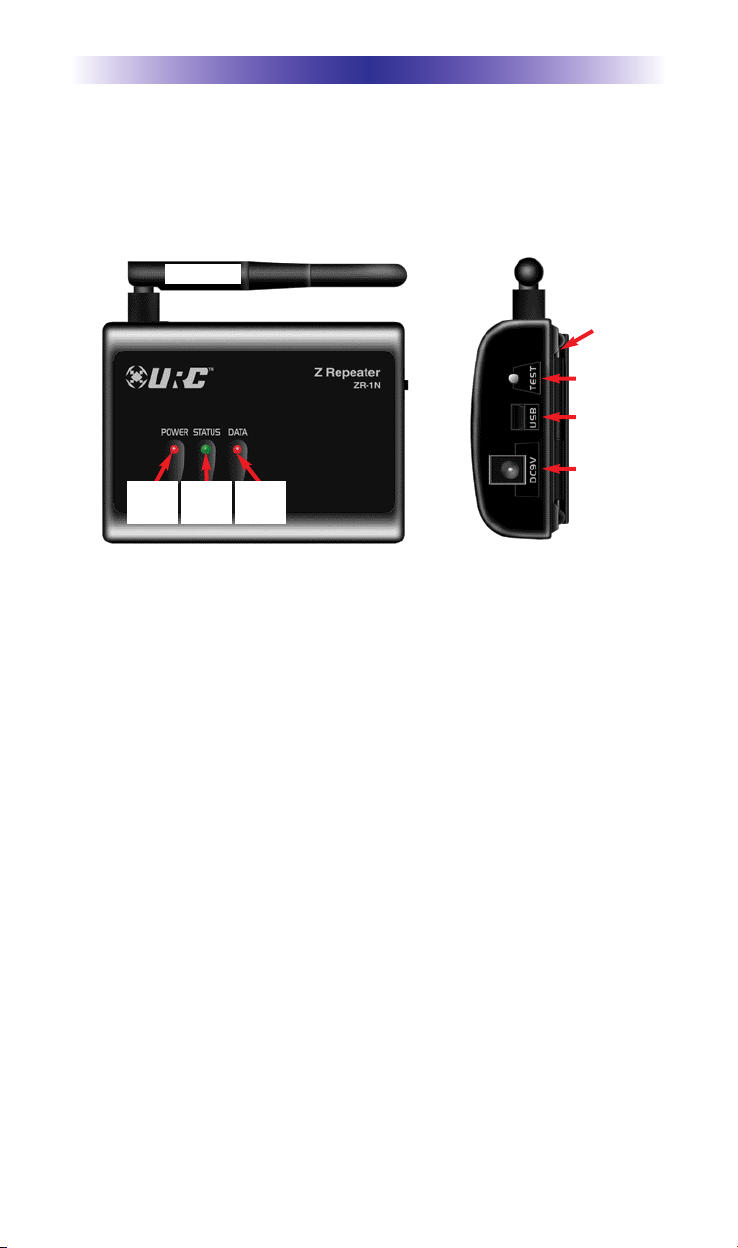
ZR-1N Front and Side Panel Descriptions
The front panel consists of 3 indicator lights which will illuminate
when in use.
Antenna
Mounting
Plate
TEST
USB
DC9V
POWER
STATUS
LED
DATA
LED
LED
Power LED: Indicates that the ZR-1N is powered on when illuminated.
Status LED: The LED will show what the RF signal strength of the
ZR-1N to the MRX-10. By pressing the TEST button on the side of
the unit, it will indicate the signal strength. When the LED is:
Power
. OFF: The ZR-1N is not testing for signal strength, and the TEST
button should be pressed.
. Orange: The signal strength is LOW, and the ZR-1N should be
move to a different location
. Green: The signal strength is GOOD, and the ZR-1N is in a
good location.
Data LED: The LED will flash RED when the unit is transmitting or
receiving data.
Antenna: Omnidirectional antenna. Adjust the antenna for best performance. Usually vertical positioning works well.
DC9V Power: Attach the included 9V DC power supply here.
Mounting Plate: May be attached to a wall or other surface with the
included screws for easy slide on/off mounting.
Page 2
 Loading...