

Page 1
Page 2

Page 3

Smart 1-Line
TM
Instruction Manual Rev 1.01 www.utilityrelay.com
Page 1
For latest version, visit:
http://www.utilityrelay.com/Side_Bar/Instruction_Manuals.html
Manual Revision 1.01 – June 2019
Table of Contents
Section: Page
1.0 Introduction and Overview ..................................................................................... 4
1.1 Typical System Diagrams ................................................................................ 5
1.1.1 RS-485 Direct Connection ...................................................................... 5
1.1.2 External RS-485-to-Ethernet Modbus Gateway (optional) ..................... 6
1.1.3 Local Smart 1-Line + Remote Smart 1-Line ........................................... 6
1.2 Items Included .................................................................................................. 7
1.3 Accessories ...................................................................................................... 7
1.4 Warnings .......................................................................................................... 7
2.0 Installation ............................................................................................................... 8
2.1 Mounting .......................................................................................................... 8
2.2 Connections ..................................................................................................... 8
2.3 RS-485 Network ............................................................................................... 9
2.3.1 Cable and Lengths ................................................................................. 9
2.3.2 Termination circuits ................................................................................ 9
2.4 Ethernet (optional)............................................................................................ 9
2.4.1 External RS-485-to-Ethernet Gateway/Server ....................................... 9
2.4.2 Modbus TCP communications to other systems .................................. 10
3.0 Setup and Configuration ...................................................................................... 10
3.1 Powering On .................................................................................................. 10
3.1.1 Logging into Windows .......................................................................... 10
3.1.2 Designer Mode ..................................................................................... 11
3.1.2.1 Designer Mode Password ...................................................... 11
3.1.2.2 Drawing your 1-Line ............................................................... 11
3.1.2.3 Adding items .......................................................................... 11
3.1.2.4 Rotating items ........................................................................ 11
3.1.2.5 Removing items ..................................................................... 11
3.1.2.6 Power Distribution System Changes ..................................... 11
3.1.2.7 Designer Mode Toolbar ......................................................... 12
3.1.2.8 Smart 1-Line Settings ............................................................ 14
3.1.2.9 Modbus Settings .................................................................... 14
3.1.2.10 Timing Settings .................................................................... 16
3.1.2.11 Modbus Server Settings ...................................................... 17
3.1.2.12 Preferences Settings ........................................................... 18
3.1.2.13 User Logo ............................................................................ 18
3.1.2.14 Diagnostics (settings) .......................................................... 19
3.1.3 Trip Unit Settings .................................................................................. 20
3.1.3.1 AC-PRO-II Device Settings .................................................... 20
3.1.3.2 AC-PRO Device Settings ....................................................... 20
4.0 Operation ............................................................................................................... 21
4.1 Run Mode ....................................................................................................... 21
4.1.1 Breaker Block ....................................................................................... 22
4.1.2 Detailed Breaker Data .......................................................................... 23
4.1.2.1 Readings tab (AC-PRO-II only) ............................................. 24
4.1.2.2 Tripping a Breaker: ................................................................ 26
4.1.2.3 Waveforms tab (AC-PRO-II only, FW v2.0.27 or higher)....... 27
4.1.2.4 Trip History tab (AC-PRO-II only) .......................................... 28
4.1.2.5 Settings tab (AC-PRO-II only) ................................................ 29
4.1.2.6 TCC/Tests tab (AC-PRO-II only) ........................................... 30
4.1.2.7 AC-PRO tab (includes Readings, Settings, Last Trip) ........... 31
4.1.2.8 Breaker Tests tab................................................................... 32
4.1.2.9 Trip Unit Tests tab.................................................................. 33
4.1.3 Transformer .......................................................................................... 33
Page 4

Smart 1-Line
TM
Instruction Manual Rev 1.01 www.utilityrelay.com
Page 2
4.1.4 Bus ....................................................................................................... 34
4.1.5 Description Box .................................................................................... 34
4.1.6 Voltage data block ................................................................................ 34
4.1.7 Power data block .................................................................................. 34
4.1.8 Energy data block ................................................................................. 35
4.1.9 Trip unit icons ....................................................................................... 35
4.1.10 Communications Status Box ............................................................... 36
4.1.11 Designer Mode button ......................................................................... 36
4.1.12 Help button .......................................................................................... 36
5.0 Software and Firmware ......................................................................................... 37
5.1 Features by product & version ....................................................................... 37
6.0 System performance & speed.............................................................................. 38
6.1 Smart 1-Line Settings..................................................................................... 38
6.2 Baud Rate ...................................................................................................... 38
6.3 Power state of AC-PRO-II and/or AC-PRO trip units ..................................... 38
7.0 General and PC Items ........................................................................................... 38
7.1 Operating System .......................................................................................... 39
7.2 Internet and/or Server Connections ............................................................... 39
7.3 PC & Windows Settings ................................................................................. 39
7.3.1 Windows Accounts and Passwords ..................................................... 39
7.3.1.1 “Smart 1-Line” user account .................................................. 39
7.3.1.2 “Administrator” account .......................................................... 39
7.3.2 Screen Timeout and Brightness settings ............................................. 40
7.4 Other applications .......................................................................................... 40
7.5 Other Modbus devices ................................................................................... 40
7.6 Panel PC Specifications ................................................................................. 41
7.7 Warranty ......................................................................................................... 41
7.8 Software updates ........................................................................................... 41
7.9 Troubleshooting ............................................................................................. 42
7.10 General Troubleshooting items ...................................................................... 42
7.11 Getting Logs ................................................................................................... 42
Page 5

Smart 1-Line
TM
Instruction Manual Rev 1.01 www.utilityrelay.com
Page 3
Table of Figures
Figure 1: Smart 1-Line with 1-Line screen example ................................................... 4
Figure 2: Typical Diagram #1: RS-485 Direct (Modbus RTU) .................................... 5
Figure 3: Typical Diagram #2: External Modbus Gateway (Modbus TCP) ............... 6
Figure 4: Typical Diagram #3: Local Smart 1-Line + Remote Smart 1-Line ............. 6
Figure 5: VESA Mounting holes ................................................................................... 8
Figure 6: Rear Connections .......................................................................................... 8
Figure 7: Typical RS-485 Network Wiring Diagram .................................................... 9
Figure 8: RS-485 Maximum Recommended Cable Lengths ...................................... 9
Figure 9: Designer Mode Button ................................................................................ 10
Figure 10: Designer Mode Password ......................................................................... 11
Figure 11: Designer Mode Toolbar ............................................................................ 12
Figure 12: Designer Mode 1-Line Drawing example ................................................ 13
Figure 13: Settings Menu ............................................................................................ 14
Figure 14: Modbus Settings - Example for RS-485 Direct Connection .................. 15
Figure 15: Modbus Settings - Example for External Gateway connection ............ 15
Figure 16: Timing Settings.......................................................................................... 16
Figure 17: Modbus Server Settings ........................................................................... 17
Figure 18: Preferences Settings ................................................................................. 18
Figure 19: Browse to Customer Logo Window ........................................................ 18
Figure 20: Diagnostics (settings) ............................................................................... 19
Figure 21: Run Mode 1-Line Diagram example ........................................................ 21
Figure 22: Breaker Block: example states ................................................................ 22
Figure 23: Breaker symbol - area to tap .................................................................... 23
Figure 24: Breaker Data Window General Layout .................................................... 23
Figure 25: Readings Tab (AC-PRO-II only)................................................................ 25
Figure 26: Trip Breaker steps ..................................................................................... 26
Figure 27: Waveforms Tab (AC-PRO-II only) ............................................................ 27
Figure 28: Trip History Tab (AC-PRO-II only) ........................................................... 28
Figure 29: Settings Tab (AC-PRO-II only) .................................................................. 29
Figure 30: TCC/Tests Tab (AC-PRO-II only) .............................................................. 30
Figure 31: AC-PRO Tab ............................................................................................... 31
Figure 32: Breaker Tests Tab ..................................................................................... 32
Figure 33: Trip Unit Tests Tab .................................................................................... 33
Figure 34: Communications Status Box ................................................................... 36
Page 6
Smart 1-Line
TM
Instruction Manual Rev 1.01 www.utilityrelay.com
Page 4
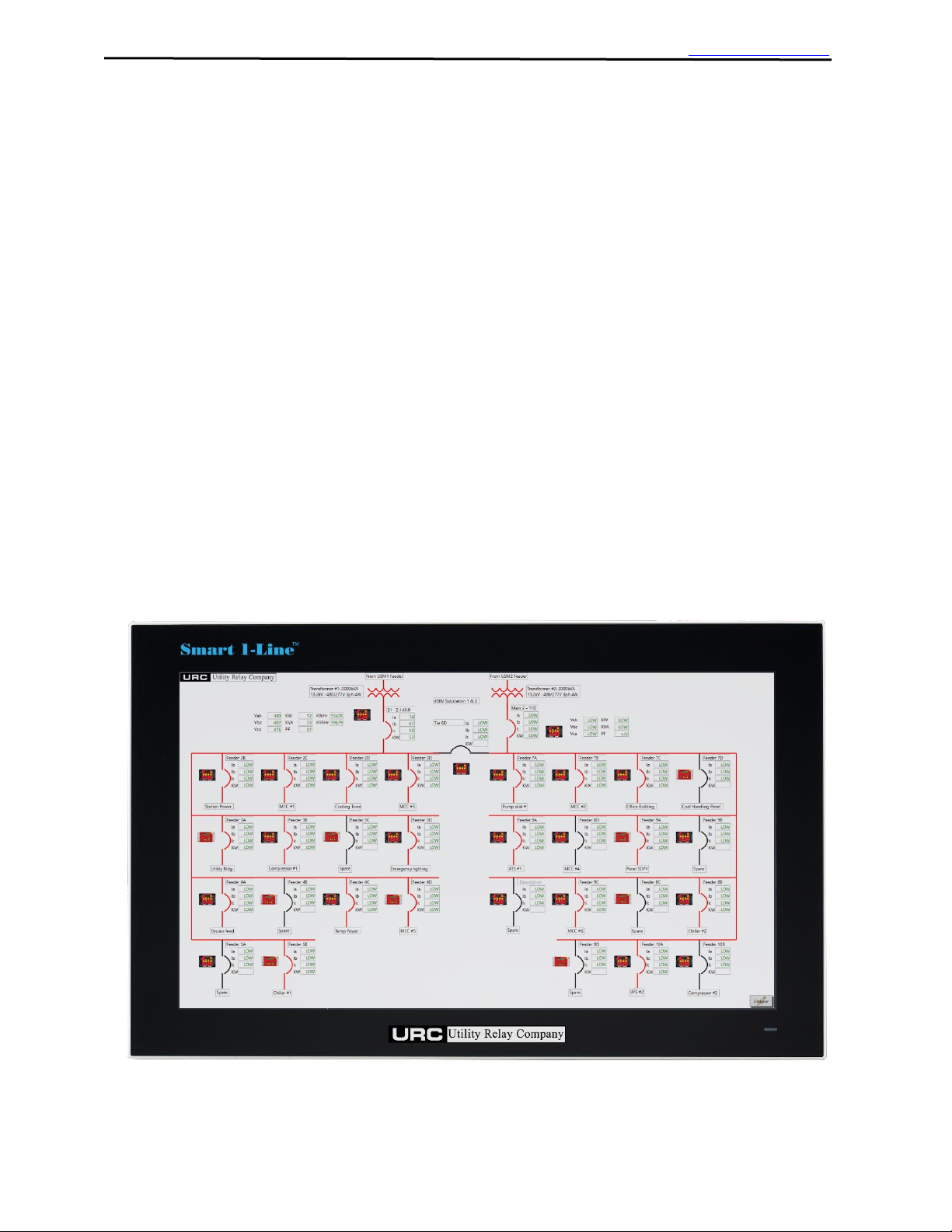
Based on a rugged, fanless, touch screen industrial computer with a solid state drive and a 21.5"
high-definition touchscreen, the Smart 1-Line™ is URC's modern turn-key solution for monitoring
your AC-PRO-II® and AC-PRO® networks at one convenient location. It displays a field-configurable
electronic 1-Line diagram with breaker readings, status, and more. Simply tapping (clicking) a
breaker symbol provides additional details and information.
The Smart 1-Line™ features include:
• Turn-key solution for monitoring URC products via Modbus communications
• Monitor Current, Voltage, Power, Energy, Breaker status, Waveforms*, Alarms, and more
• Industrial PC with High Definition 21.5" Color Touch Screen, Solid State Drive, no moving
parts (no cooling fans, etc)
• Software Pre-Installed
• Field Configurable Electronic 1-Line Diagram
• Remote Breaker Tripping
• View Time Current Curves* and Test Data
• Wall Mount Design for Switchgear or Control Room
(mount can be supplied by URC or Customer)
• RS-485 Communications to AC-PRO & AC-PRO-II
• Ethernet Port for Modbus TCP communications from external gateway,
or to separate system
• Smart 1-Line will provide the most features, highest communications speeds, and most
future capability when used with AC-PRO-II with VDM (Voltage Divider Module) trip units.
• Refer to Section 5 for additional features details.
*Feature available for AC-PRO-II only. See Section 5 for specific firmware versions.
Figure 1: Smart 1-Line with 1-Line screen example
1.0 Introduction and Overview
Page 7
Smart 1-Line
TM
Instruction Manual Rev 1.01 www.utilityrelay.com
Page 5
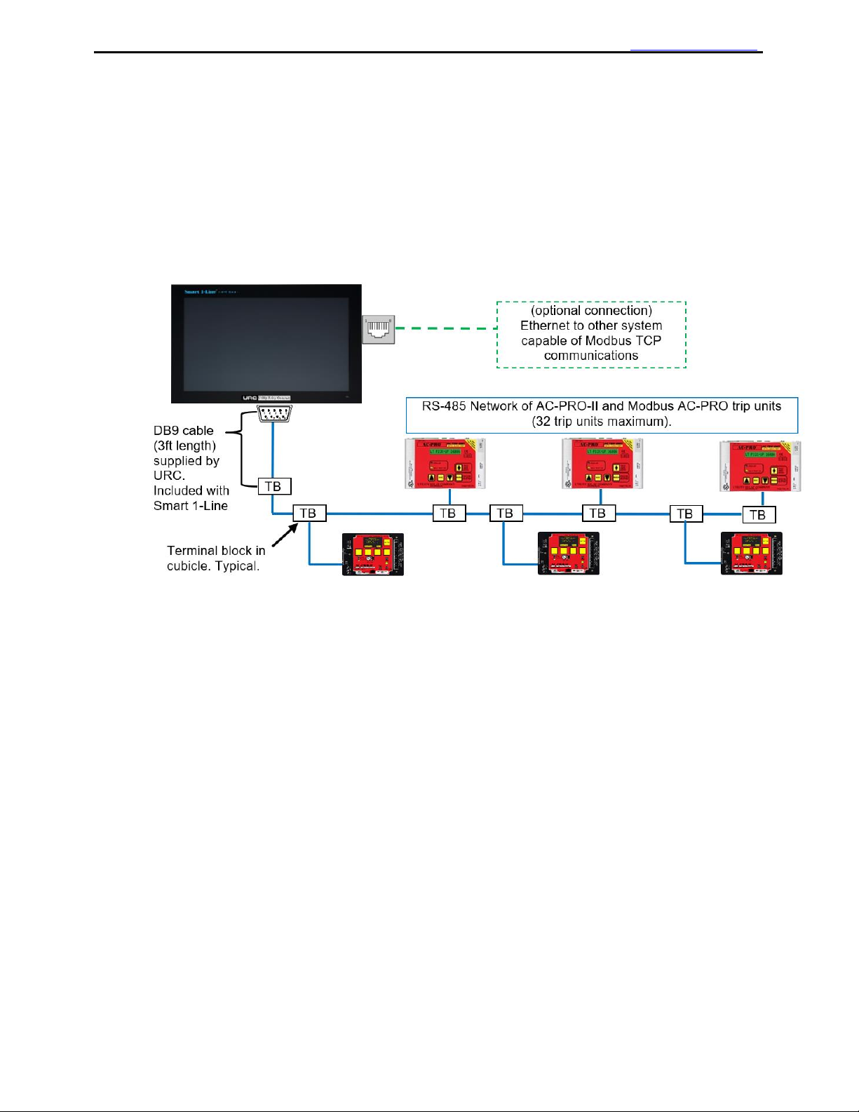
The Smart 1-Line can communicate with the network of trip units using a direct RS-485 connection,
or via an Ethernet connection from a customer-supplied External RS-485-to-Ethernet Modbus
Gateway.
1.1.1 RS-485 Direct Connection
The standard method for connecting trip units to the Smart 1-Line is a Direct RS-485 connection to
the serial port on the Smart 1-Line. See the figure below for an example. See Section 3 for Settings.
Figure 2: Typical Diagram #1: RS-485 Direct (Modbus RTU)
1.1 Typical System Diagrams
Page 8
Smart 1-Line
TM
Instruction Manual Rev 1.01 www.utilityrelay.com
Page 6
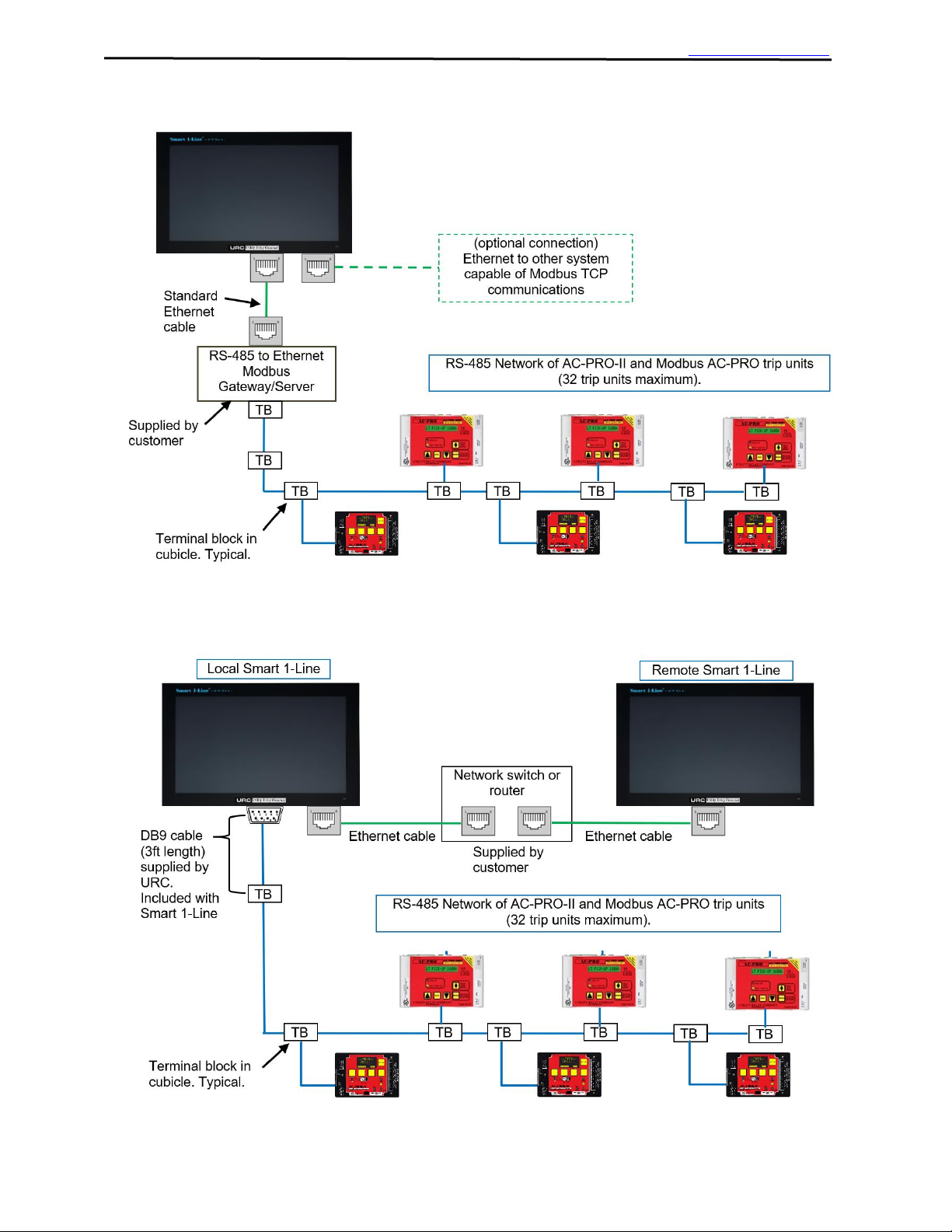
1.1.2 External RS-485-to-Ethernet Modbus Gateway (optional)
Figure 3: Typical Diagram #2: External Modbus Gateway (Modbus TCP)
1.1.3 Local Smart 1-Line + Remote Smart 1-Line
Figure 4: Typical Diagram #3: Local Smart 1-Line + Remote Smart 1-Line
Page 9

Smart 1-Line
TM
Instruction Manual Rev 1.01 www.utilityrelay.com
Page 7
• Smart 1-Line Touchscreen Panel PC with software pre-loaded
• 120VAC to 12-24V Power Supply
• RS-485 cable with DB9 connector (3 ft. length) (URC part #CA-10-100)
• RS-485 terminal block (URC part #T-119) with mounting hardware & ring terminals
• Wall mount can be supplied by URC or by Customer
• USB Keyboard and mouse (customer supplied) are recommended for convenience for initial
setup, but not required for normal operation. Any standard USB keyboard and
mouse/pointing device should be compatible. See below for some items URC has used
successfully.
• Mounting: See Section 2 for mounting information and options.
• Some examples if items URC has used along with the Smart 1-Line:
o USB keyboard (IP 65 washable): Perixx PERIBOARD-517 (available on
Amazon.com)
o USB mouse: Adesso iMouse W3 Waterproof with Magnetic Scroll Wheel (available
on Amazon.com)
o Heavy-duty Industrial Keyboard/Mouse folding shelf: RackSolutions Full Keyboard
Wallmount (available on Amazon.com)
o USB hubs & extenders: Sabrent USB hubs and extenders (available on
Amazon.com)
WARNING!
1. The Smart 1-Line information should not be exclusively relied on for situations that are critical to
human safety and/or prevention of damage to equipment. All conditions shall be verified by
separate means.
2. The Smart 1-Line MUST be updated if power distribution system changes occur. Examples are
replacing breakers, exchanging breakers, new breakers or loads, switchgear modifications, etc.
For example, if breakers are exchanged, trip unit addresses, breaker names, load descriptions,
etc. must be reviewed and changed accordingly.
1.2 Items Included
1.3 Accessories
1.4 Warnings
Page 10
Smart 1-Line
TM
Instruction Manual Rev 1.01 www.utilityrelay.com
Page 8
Mounting hardware can be supplied by URC or by the Customer.
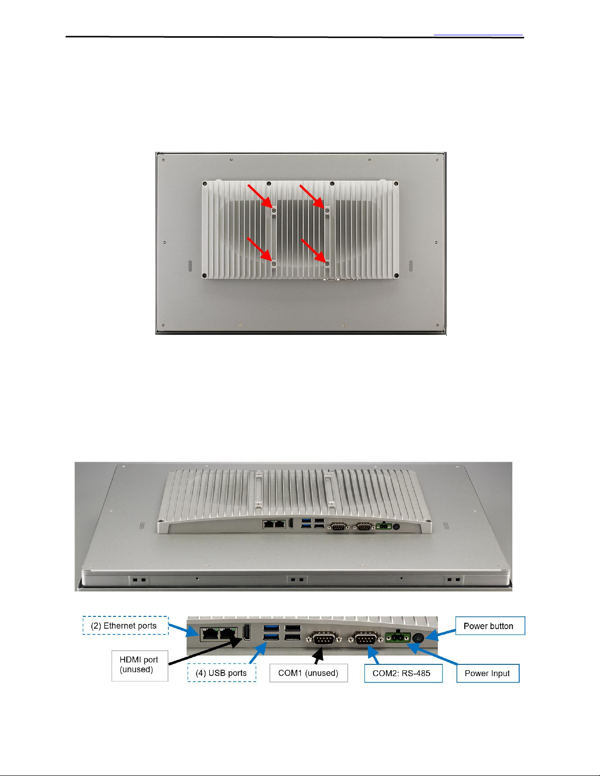
The Smart 1-Line is designed for surface wall-mounting, using its standard 100mm x 100mm VESA
hole pattern.
Figure 5: VESA Mounting holes
Any heavy duty VESA 100mm x 100mm capable of supporting 30 lbs can be used.
(The Panel PC weighs approximately 15 lbs).
If specified, URC can supply the Panel PC OEM wall mount kit along with the Smart 1-Line.
Contact URC for additional information.
Figure 6: Rear Connections
2.0 Installation
2.1 Mounting
2.2 Connections
Page 11
Smart 1-Line
TM
Instruction Manual Rev 1.01 www.utilityrelay.com
Page 9
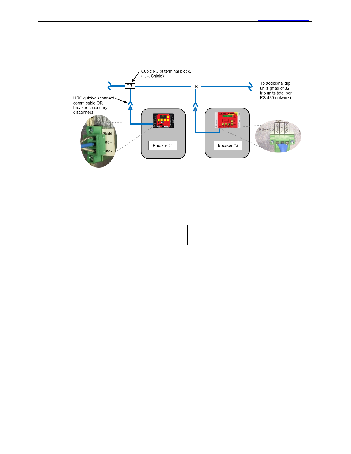
Trip units are “daisy-chained” using a twisted-shielded cable as shown in the example diagram
below.
Figure 7: Typical RS-485 Network Wiring Diagram
2.3.1 Cable and Lengths
A Belden #9463 cable or equivalent can be used for the twisted shielded pair cable.
Refer to the table below for maximum recommended cable lengths:
Baud Rate
9600
19200
38400
57600
115200
Maximum
Cable length
4000 ft
4000 ft
4000 ft
2000 ft
1000 ft
Trip Units
AC-PRO or
AC-PRO-II
AC-PRO-II ONLY
Note: communications success with maximum lengths may vary depending on the environment.
Figure 8: RS-485 Maximum Recommended Cable Lengths
Note: the above maximum lengths are based on URC testing of direct RS-485 connection to
The Smart 1-Line.
2.3.2 Termination circuits
URC does NOT recommend “typical” RS-485 external “R” or “RC” termination circuits for use with
AC-PRO-II and AC-PRO RS-485 wiring.
The AC-PRO-II features an internal termination network, which can be switched ON or OFF via a
front accessible switch. This switch should be in the ON position for the “last” AC-PRO-II in the
“loop” (RS-485 network). The switch should be in the OFF position for all other trip units in the loop
(RS-485 network).
2.4.1 External RS-485-to-Ethernet Gateway/Server
If an external customer-supplied RS-485-to-Ethernet Modbus Gateway/Server is utilized, it must be
configured to work with the Smart 1-Line.
2.3 RS-485 Network
2.4 Ethernet (optional)
Page 12

Smart 1-Line
TM
Instruction Manual Rev 1.01 www.utilityrelay.com
Page 10
Though most of these gateways are standard “off-the-shelf” products that should work well, each
product is different and URC cannot guarantee the Smart 1-Line will work with all gateways.
Please contact URC with questions about external RS-485-to-Ethernet Gateways.
URC has used and tested the following products successfully with the Smart 1-Line:
• Moxa MGate MB3180
• Lantronix XPRESS DR
If using an external RS-485-to-Ethernet Modbus Gateway/Server, it must be configured with the
following settings:
• Modbus TCP Exception should be Disabled
• Response Timeout should be set to a shorter duration than the Smart 1-Line “Trip Unit
Response Timeout” setting.
2.4.2 Modbus TCP communications to other systems
When the RS-485 network is wired directly to the Smart 1-Line, the Smart 1-Line can act as a
“Modbus server” to other systems (“clients”).
Requirements for using the Smart 1-Line as a “Modbus server” to other systems:
• “Other systems” must be capable of Modbus communications
• “Other systems” must have drivers for AC-PRO-II and/or AC-PRO. A “driver” is simply
application programming that enables the system to correctly interpret the AC-PRO-II or
AC-PRO Register Map.
• Smart 1-Line “Modbus Server Settings” must be configured properly.
See Section 3 of this manual.
Ensure the included Power supply is connected to a reliable 120VAC source, and that the power
supply is also connected to the Panel PC.
Press the Power button to turn on the Smart 1-Line.
3.1.1 Logging into Windows
After Powering the Smart 1-Line, or after a screen timeout, you will be prompted for your Windows
Username and Password.
If logging into Windows for the first time, use the Smart 1-Line User account Username and
password provided by URC.
URC recommends changing the Smart 1-Line User account password. To change your
Smart 1-Line password, you must log into the Administrative account. See Section 7.
After logging in, the Smart 1-Line application will start automatically.
After the Smart 1-Line application starts, click or tap the “Designer” button in the bottom right corner
to start creating your 1-Line in Designer Mode.
Figure 9: Designer Mode Button
3.0 Setup and Configuration
3.1 Powering On
Page 13
Smart 1-Line
TM
Instruction Manual Rev 1.01 www.utilityrelay.com
Page 11
3.1.2 Designer Mode
3.1.2.1 Designer Mode Password
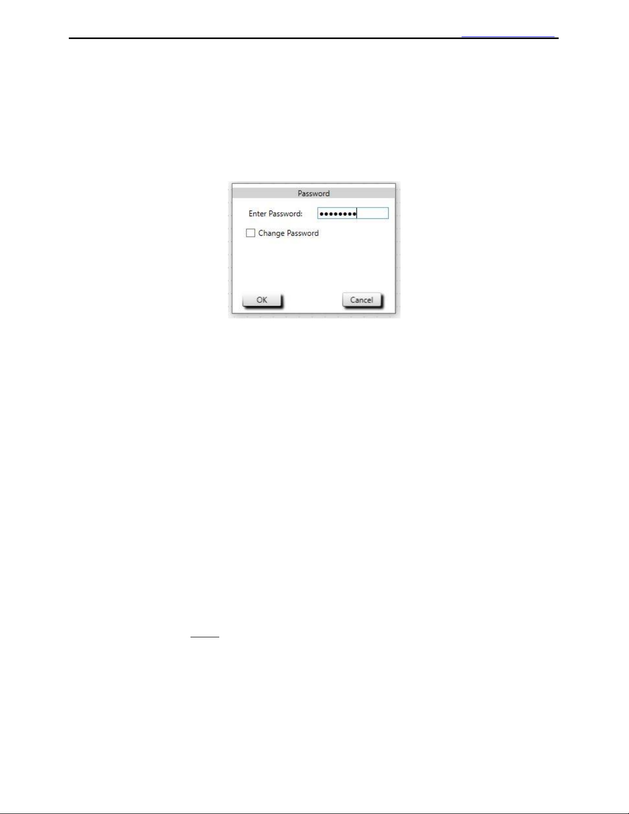
After clicking the “Designer” button, you will be prompted for the Designer Mode password.
Use the password provided by URC.
To change your password, check the Change Password box, and you will be prompted
to follow the instructions.
Figure 10: Designer Mode Password
3.1.2.2 Drawing your 1-Line
After entering the Designer Mode password, you can start building or editing your 1-line diagram.
If you are entering Designer Mode for the first time, the drawing area will be blank.
The Designer Mode toolbar contains all of the items and settings required to setup your system.
3.1.2.3 Adding items
In Designer Mode: To add items to your Smart 1-Line, simply tap or click an item in the toolbar, and
then tap or click in the drawing area.
3.1.2.4 Rotating items
In Designer Mode:
The Breaker and Transformer items can be rotated 90 degrees by double-tapping or double-clicking.
The Bus items can be stretched and rotated using the “grips” on each end of the line.
3.1.2.5 Removing items
In Designer Mode:
Items can be removed by dragging them off the screen to the right.
3.1.2.6 Power Distribution System Changes
The Smart 1-Line MUST be updated if power distribution system changes occur. Examples are
replacing breakers, exchanging breakers, new breakers or loads, switchgear modifications, etc. For
example, if breakers are exchanged, trip unit addresses, breaker names, load descriptions, etc. must
be reviewed and changed accordingly.
In addition, if breakers are known to be out of service for an extended period, temporarily clear the
Smart 1-Line address fields for those breakers, or temporarily remove those breakers from the Smart
1-line drawing. The reason for this is: if these breakers/addresses are left in the Smart 1-Line
drawing, then the Smart 1-Line will try to communicate with these units. The communications
system performance is slowed down when the Smart 1-Line attempts to communicate with units that
are out of service and not responding.
Page 14
Smart 1-Line
TM
Instruction Manual Rev 1.01 www.utilityrelay.com
Page 12
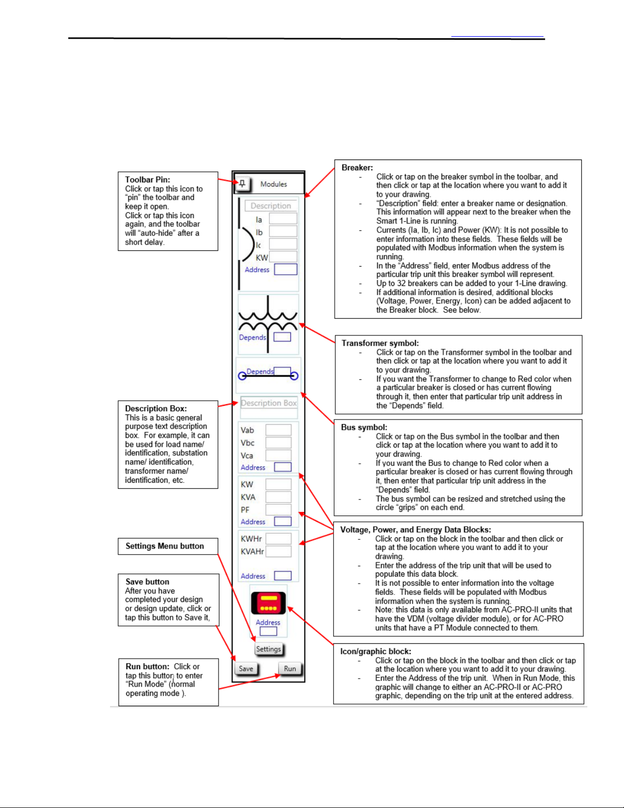
3.1.2.7 Designer Mode Toolbar
Using the Designer Mode toolbar, simply click or tap on the symbol/item you want to add, and then
click or tap at the location where you want to add it.
After items are added to your drawing, they can easily be moved around by clicking or tapping on the
item, and then dragging to the desired location.
Figure 11: Designer Mode Toolbar
Page 15

Smart 1-Line
TM
Instruction Manual Rev 1.01 www.utilityrelay.com
Page 13
Figure 12: Designer Mode 1-Line Drawing example
Page 16

Smart 1-Line
TM
Instruction Manual Rev 1.01 www.utilityrelay.com
Page 14
3.1.2.8 Smart 1-Line Settings
The Smart 1-Line ships with “default” settings.
For most installations, only some Smart 1-Line settings will need to be re-configured.
The Smart 1-Line settings can be accessed by using the Designer Mode Toolbar. See Figure 12.
Tap or click the Settings button. This will launch the following Smart 1-Line settings menu.
Figure 13: Settings Menu
3.1.2.9 Modbus Settings
Tap or click the “Modbus” button to access the Modbus Configuration settings.
There are two possible methods for connecting trip units to the Smart 1-Line.
Refer to Figures 14 and 15.
Select “Modbus RTU” and “COM2” if your trip unit RS-485 network connects directly to the
Smart 1-Line Serial port. (See Figure 2). See example setting window below.
Select the “Baud rate”.
IMPORTANT: The Baud rate setting on the Smart 1-Line and ALL of the trip units MUST be set to
the same Baud Rate.
NOTE: If any AC-PRO trip units are connected to the RS-485 network, then the Smart 1-Line and
ALL trip units must be set to 9600. (the AC-PRO baud rate is fixed at 9600).
Select the “Parity” to match the trip unit settings. The Parity setting on the Smart 1-Line and all of the
trip units MUST be set to the same setting.
Page 17

Smart 1-Line
TM
Instruction Manual Rev 1.01 www.utilityrelay.com
Page 15
Figure 14: Modbus Settings - Example for RS-485 Direct Connection
Select “Modbus TCP” if your trip unit R-485 network connects to an external Ethernet gateway.
(See Figure 3) See example setting window below.
Enter either the Server name or the IP address of the external Ethernet gateway device.
Enter the Modbus port of the external Ethernet gateway device.
Figure 15: Modbus Settings - Example for External Gateway connection
Page 18

Smart 1-Line
TM
Instruction Manual Rev 1.01 www.utilityrelay.com
Page 16
3.1.2.10 Timing Settings
URC recommends using the default Timing Settings unless changes are necessary due to the
presence of multiple clients or systems.
If desired or needed for external communications, the Timing settings can be adjusted. This is
typically only necessary if additional systems will be connected to the Smart 1-Line. Otherwise, the
recommended default settings are shown below.
NOTE: Improper adjustment of Timing Settings can result in communications issues.
Scan Period:
Adjusts how frequently the Smart 1-Line requests data from each trip unit. For example, if this
setting is set to 10 seconds, the information for each breaker will be requested (and should be
updated) every 10 seconds.
Trip Unit Response Timeout:
Adjusts how long the Smart 1-Line will wait for a reply from each trip unit.
Number of Retries per Request:
Adjusts how many times the Smart 1-Line will retry a data request before determining that the trip
unit is not responding.
If Trip Unit Does Not Respond:
Scan Periods to Stop Trying:
Adjusts how many consecutive unsuccessful scan periods can occur before the Smart 1-Line will
temporarily stop making requests to a trip unit.
Resume Trying After:
Applies after the above number of “Scan Periods to Stop Trying” has been met. Adjusts the duration
after which the Smart 1-Line will re-attempt requests to a trip unit.
Figure 16: Timing Settings
Page 19

Smart 1-Line
TM
Instruction Manual Rev 1.01 www.utilityrelay.com
Page 17
3.1.2.11 Modbus Server Settings
These settings only need to be adjusted if the Smart 1-Line will provide Modbus data to other
equipment or systems. Otherwise, the default settings should be used.
If the trip units are connected to the Smart 1-Line via RS-485, the Smart 1-Line can serve data to
“other systems”, via its internal Modbus Server application. If “other systems” will obtain data from
the Smart 1-Line, the Modbus Server settings will need to be changed.
Max Number of Clients:
This setting determines the maximum number of “clients” that will be allowed to request data from
the Modbus Server. Internally, the Smart 1-Line has 2 clients, and thus the minimum (and default)
setting is 2. If “other systems” will be obtaining data from the Smart 1-Line, the number needs to be
incremented for each additional system.
If a “local” and a “remote” Smart 1-Line will be connected to the same system,
this setting should be 4.
Max Number of Queued Messages:
This is an advanced setting. The Modbus Server receives messages from Modbus Clients and
sends them to Trip Units over RS485. If a new message from a client is received before a Trip Unit
responds, it’s queued and, after the Trip Unit response (or timeout), sent to a Trip Unit. Modbus
Server can queue up to “Max Number of Queued Messages”. After that, new messages from
Modbus Clients are ignored.
Modbus Port:
This is an advanced setting. Well-known TCP port 502 is reserved for the Modbus Application
Protocol. Avoid any other well-known ports. Make sure there are no conflicts if using a port other
than 502. Refer to “Service Name and Transport Protocol Port Number Registry” at
https://www.iana.org/assignments/service-names-port-numbers/service-names-portnumbers.xhtml and RFC6335 at
https://www.iana.org/assignments/service-names-port-numbers/service-names-port-numbers.xhtml
Trip Unit Response Timeout:
Adjusts how long the Modbus Server will wait for a reply from each trip unit.
Figure 17: Modbus Server Settings
Page 20

Smart 1-Line
TM
Instruction Manual Rev 1.01 www.utilityrelay.com
Page 18
3.1.2.12 Preferences Settings
If this box is checked, the breakers and items will change to Red if the breaker or associated breaker
is closed and/or if current is flowing.
If this box is not checked, the breakers and items will not turn Red, regardless of breaker position
and current.
Figure 18: Preferences Settings
3.1.2.13 User Logo
If desired, a Logo image file can be imported and can appear in the upper right corner of the Smart
1-Line when it is in Run Mode. The image file format can be .png, .jpg, .gif, or .bmp. One example
logo size (resolution) is 280 x 80. This size allows for a legible logo, but does not take up too much
room on the Smart 1-Line screen. However, any size logo can be used. For reference &
consideration, the entire Smart 1-Line screen is 1920 x 1080. Hence, a 1920 x 1080 logo would use
up the whole screen, making zero 1-Line items visible. See Figure 20 for an example that shows a
logo in the upper right corner.
Figure 19: Browse to Customer Logo Window
Page 21

Smart 1-Line
TM
Instruction Manual Rev 1.01 www.utilityrelay.com
Page 19
3.1.2.14 Diagnostics (settings)
The Diagnostics settings window includes the following settings:
• Show / Don’t show Communications Status Box. This box appears in the lower left corner
when in Run Mode. See Section 4.1.10 for additional information about the
Communications status box.
• Log Level: This setting should remain at the default setting unless directed by URC for
troubleshooting purposes. This setting determines how much information the Smart 1-Line
logs software events internally. A setting of 1 represents the least amount of data logging.
A setting of 5 represents the largest amount of data logging. The default setting is 4. Do not
change this setting unless instructed to by URC.
Figure 20: Diagnostics (settings)
Page 22

Smart 1-Line
TM
Instruction Manual Rev 1.01 www.utilityrelay.com
Page 20
3.1.3 Trip Unit Settings
3.1.3.1 AC-PRO-II Device Settings
The AC-PRO-II device settings must be configured correctly for successful communications with the
Smart 1-Line to be established.
The AC-PRO-II RS485 communications settings can easily be changed as these settings are part of
the standard “Change Settings” sequence that can be performed using the AC-PRO-II screen and
buttons. Refer to the AC-PRO-II Instruction Manual
The following AC-PRO-II settings must be correctly configured:
• RS-485 Communications Enabled setting must be set to ON.
• Address must be set to match the address of the corresponding items on the 1-Line
diagram. The address must be unique (a single address cannot be used for
multiple trip units).
• Baud Rate must be set to match the Smart 1-Line or external gateway baud rate setting.
• Parity must be set to match all other trip units & Smart 1-Line. If there are any AC-PRO trip
units on the RS-485 network, set the AC-PRO-II parity to None. Otherwise, set AC-PRO-II
trip units to Odd or Even.
• Reply Delay (if present) is recommended to be set to the minimum setting when used with
the Smart 1-Line.
• Forced Trip can either be set to ENABLE or DISABLE. Set to ENABLE if you want to be
able to trip the breaker using the Smart 1-Line.
• Settings Change Over Comm can either be set to ENABLE or DISABLE. However,
presently, regardless of this setting, the Smart 1-Line is not capable of changing
trip unit settings.
• Alarm (Relay) settings are user programmable. If you want the Smart 1-Line to indicate an
alarm has occurred, this alarm must be set/enabled at the trip unit. See the AC-PRO-II
Instruction Manual for additional information (NOTE: Trips will be “alarmed” on the
Smart 1-Line regardless of trip unit alarm settings).
3.1.3.2 AC-PRO Device Settings
The AC-PRO device settings must be configured correctly for successful communications with the
Smart 1-Line to be established.
The AC-PRO RS485 communications settings can easily be changed as these settings are part of
the standard “Change Settings” sequence that can be performed using the AC-PRO screen and
buttons. Refer to the AC-PRO Instruction Manual.
The following AC-PRO settings must be correctly configured:
• Address must be set to match the address of the corresponding items on the 1-Line
diagram. The address must be unique (a single address cannot be used for
multiple trip units).
• Reply Delay (if present) is recommended to be set to the minimum setting when used with
the Smart 1-Line.
• Forced Trip can either be set to ON or OFF. Set to ON if you want to be able to trip the
breaker using the Smart 1-Line.
Page 23

Smart 1-Line
TM
Instruction Manual Rev 1.01 www.utilityrelay.com
Page 21
The normal operating mode of the Smart 1-Line is “Run Mode”. In this mode of operation, the Smart
1-Line will periodically request information from each trip unit (breaker). It will use this information to
update the values and graphics on the 1-Line diagram. Specifically, it will request info from each
unique trip unit address that is included in the “Designer Mode” 1-Line diagram.
Figure 21: Run Mode 1-Line Diagram example
4.0 Operation
4.1 Run Mode
Page 24

Smart 1-Line
TM
Instruction Manual Rev 1.01 www.utilityrelay.com
Page 22
4.1.1 Breaker Block
In Run Mode, the Breaker Block indicates:
• Phase current values (Ia, Ib, Ic)
o Green values indicate data obtained from the trip unit.
• Total real power value (KW) (appears if an AC-PRO-II with Voltage Divider Module or
AC-PRO with PT Module is connected)
• Breaker position status and communication status
o Red = Energized/Closed, Communications active (see Section 3 for “Preference”
setting)
o Black = Open or Unknown, Communications active (see Section 3 for “Preference”
setting)
▪ NOTE: This state is described as Open or Unknown as many breakers are
not presently supplied with URC limit switches. Therefore, in many
applications, current flow is used to indicate position, and even if current is
“Low”, the breaker could still be closed.
o Gray = Trip unit not communicating
• Breaker Tripped indication (Red “X” appears)
• Alarm indication (Red bell symbol flashes)
o Trip occurred, Current greater than LT Pickup setting, and Actuator open circuit
conditions will always result in Alarm indication
o For AC-PRO-II, indication of alarms for other conditions is possible, but the alarm
settings must be programmed at the AC-PRO-II.
• Quick-Trip indication (“QT ON” appears)
• Breaker name/description (Entered by user in Designer Mode)
The Figure below shows some example breaker states.
Figure 22: Breaker Block: example states
Page 25

Smart 1-Line
TM
Instruction Manual Rev 1.01 www.utilityrelay.com
Page 23
4.1.2 Detailed Breaker Data
While in Run Mode, any breaker that is actively communicating will have a Red symbol color or
Black symbol color. If the breaker is in this state, you can tap or click on the breaker symbol to
obtain additional information. See the Figure below for guidance on where to tap or click the symbol.
Tap or click the curved portion of the symbol, see below.
Figure 23: Breaker symbol - area to tap
After tapping or clicking on the breaker, an additional window will open.
Depending on which trip unit is present different software tabs will appear on the right side of the
window that appears.
Figure 24: Breaker Data Window General Layout
Page 26

Smart 1-Line
TM
Instruction Manual Rev 1.01 www.utilityrelay.com
Page 24
4.1.2.1 Readings tab (AC-PRO-II only)
The Readings tab will appear on the right side of the window for AC-PRO-II trip units. It provides the
following information, features, and capabilities:
• The following information will be retrieved automatically:
1. RMS Current values: Phase A, B, C, Neutral, Ground
2. Frequency
3. *If the AC-PRO-II is equipped with a Voltage Divider Module:
▪ RMS Voltage values:
• Vab, Vbc, Vca (AC-PRO-II firmware v1.9 or later)
• Van, Vbn, Vcn (AC-PRO-II firmware v1.2 – v1.8)
▪ Power values
• Real Power (KW)
• Apparent Power (KVA)
• Power Factor (PF)
▪ Energy values
• Real Energy (KWH)
• Apparent Energy (KVAH)
4. Alarms and Status:
▪ Trip occurred Alarm with reset capability
▪ Quick-Trip Switch position
▪ Breaker position (if equipped with URC limit switch)
▪ Actuator Open circuit
▪ Trip unit Alarm relay conditions (depend on trip unit version and customer
settings)
• UnderVoltage (can be reset by user)
• OverVoltage (can be reset by user)
• Phase Loss
• LT (Long Time) Pickup (phase current exceeded LT Pickup setting)
• Ground Fault (can be reset by user)
• Sluggish Breaker (can be reset by user)
• Trip (can be reset by user)
• Internal Error
• Actuator Open circuit
• Acknowledge Trip and Reset Trip Alarm
1. To Acknowledge that you are aware a Trip occurred and reset the Trip Alarm, goto
the Readings or AC-PRO tab, and tap/click the (Alarm) Reset button. This will clear
the alarm in the trip unit, and it will remove the Red X from the breaker symbol in the
Smart 1-Line. This reset button can also be used to reset some other alarms.
• See the next section for how to trip a breaker.
Page 27

Smart 1-Line
TM
Instruction Manual Rev 1.01 www.utilityrelay.com
Page 25
Figure 25: Readings Tab (AC-PRO-II only)
Page 28

Smart 1-Line
TM
Instruction Manual Rev 1.01 www.utilityrelay.com
Page 26
4.1.2.2 Tripping a Breaker:
• The “Trip Breaker” option is accessible via the Device drop down menu. For AC-PRO-II,
use the Device menu in the Readings tab. For AC-PRO, use the Device menu in the
AC-PRO tab. See the Figure below.
• In order to trip the breaker, the following is required:
The trip unit must be programmed locally to have “Forced Trips Enabled”. This is a
permissive security setting that is accessed via the Settings menu on the AC-PRO-II screen.
1. First, use the blue arrow to “Get settings” from the trip unit.
2. Select the “Trip Breaker” menu item from the Device menu.
3. Next, you will be prompted for a Security Code. The Security code is the last four
digits of the AC-PRO-II serial number.
4. After the Security Code is entered, you will be prompted to confirm that you want to
trip the breaker. Clicking or tapping on “Yes” will result in tripping the breaker.
• The trip will be logged by the AC-PRO-II as a “Forced Trip”. The AC-PRO-II will capture
detailed trip data, including currents, voltages, waveforms, breaker mechanism time, and
date/timestamp. This information can be viewed in the Trip History tab.
• Utilizing this feature to open a breaker before taking it out of service is recommended, as the
AC-PRO-II can record the breaker mechanism time for its important “First Operation”, which
provides indication if the breaker requires service. This is URC’s patented Sluggish Breaker
Detection feature. See the AC-PRO-II Instruction Manual for additional information.
Figure 26: Trip Breaker steps
Page 29

Smart 1-Line
TM
Instruction Manual Rev 1.01 www.utilityrelay.com
Page 27
4.1.2.3 Waveforms tab (AC-PRO-II only, FW v2.0.27 or higher)
The Waveforms tab will appear on the right side of the window for AC-PRO-II trip units. It provides
the following information, features, and capabilities:
• Tap or click the blue arrow at the top of the screen to capture a waveform.
• On-demand waveform capture includes:
o Current: Phase A, B, C, and Neutral
▪ RMS values
▪ Waveforms: (5 cycles)
o Voltage: Vab, Vbc, Vca (applies to AC-PRO-II with Voltage Divider Module)
▪ RMS values
▪ Waveforms (5 cycles)
o Date & Timestamp
• Waveforms can be saved to an electronic file by using the File menu, then selecting Save
As. The electronic file can be saved to the Smart 1-Line or to a customer-supplied
USB stick.
• Previously saved waveform files can be opened by using the File menu, then selecting
Open.
Figure 27: Waveforms Tab (AC-PRO-II only)
Page 30

Smart 1-Line
TM
Instruction Manual Rev 1.01 www.utilityrelay.com
Page 28
4.1.2.4 Trip History tab (AC-PRO-II only)
The Trip History tab will appear on the right side of the window for AC-PRO-II trip units. It provides
the following information, features, and capabilities:
• Detailed Trip data for the last 8 trips:
o Trip type (e.g. Long Time)
o Date & Timestamp
o RMS Currents: Phase A, B, C, Neutral, and Ground Fault
o RMS Voltages:
▪ Vab, Vbc, Vca (firmware v2.0 and later)
▪ Van, Vbn, Vcn (firmware 1.2 – v1.9)
o Breaker mechanism time(s) (Sluggish Breaker Detection)
o Trip waveform capture (firmware v2.0.27 and later)
▪ 1 cycle pre-trip and 4 cycles post trip):
▪ Current: Phase A, B, C, and Neutral
▪ Voltage: Vab, Vbc, Vca or Van, Vbn, Vcn (depending on firmware version)
o Total Trip Counts
• Trip data can be saved to an electronic file by using the File menu, then selecting Save As.
The electronic file can be saved to the Smart 1-Line or to a customer-supplied USB stick.
• Previously saved waveform files can be opened by using the File menu, then selecting
Open.
Figure 28: Trip History Tab (AC-PRO-II only)
Page 31

Smart 1-Line
TM
Instruction Manual Rev 1.01 www.utilityrelay.com
Page 29
4.1.2.5 Settings tab (AC-PRO-II only)
The Settings tab will appear on the right side of the window for AC-PRO-II trip units. It provides the
following information, features, and capabilities:
• View all AC-PRO-II settings (Read-only)
• To view settings, tap or click the blue arrow
Figure 29: Settings Tab (AC-PRO-II only)
Page 32

Smart 1-Line
TM
Instruction Manual Rev 1.01 www.utilityrelay.com
Page 30
4.1.2.6 TCC/Tests tab (AC-PRO-II only)
The TCC/Tests tab will appear on the right side of the window for AC-PRO-II trip units. It provides
the following information, features, and capabilities:
• Plot Phase Time Current Curve based on AC-PRO-II settings.
• Plot Ground Fault Time Current Curve based on AC-PRO-II settings
• Calculates expected specific trip time ranges based on current and settings
• Save TCC/Tests data to an electronic file by using the File menu, then selecting Save As.
The electronic file can be saved to the Smart 1-Line or to a customer-supplied USB stick.
• Import previously saved TCC Test files (by using the File menu, then selecting Open).
o Test trips are plotted on Time Current Curves.
• Enter TCC/Tests notes or import previously saved TCC Test file notes
• Enter or import previously saved Breaker Mechanism times, for benchmark purposes.
To Plot a Time current curve (TCC):
1. Goto the Settings tab and use the blue arrow to “Get settings”.
2. Go back to the TCC/Tests tab and tap “Plot TCC”. Use the TCC pulldown to select your Phase
or Ground.
To Plot test results:
1. First, follow the steps above to plot your TCC.
2. Enter test data in the Test Data tables. The trip tests table will automatically calculate trip times
based on settings and test currents.
3. Tap or click the “Plot Test Data” button.
Figure 30: TCC/Tests Tab (AC-PRO-II only)
Page 33

Smart 1-Line
TM
Instruction Manual Rev 1.01 www.utilityrelay.com
Page 31
4.1.2.7 AC-PRO tab (includes Readings, Settings, Last Trip)
The AC-PRO tab includes all information on one tab and will appear on the right side of the window
for AC-PRO trip units. It provides the following information, features, and capabilities:
• RMS Currents: Phase A, B, C, GF, % Unbalance
• RMS Voltages: Vab, Vbc, Vca (if equipped with PT Module)
• Power values (if equipped with PT Module):
o Real Power (KW)
o Apparent Power (KVA)
• Energy value (KWHr) (if equipped with PT Module)
• View Settings (read only)
• Last Trip data (Trip type & RMS currents)
• Quick-Trip switch position
• Breaker position status (if equipped with PT module and 52a contact wired in)
• Trip unit serial number
Figure 31: AC-PRO Tab
Page 34

Smart 1-Line
TM
Instruction Manual Rev 1.01 www.utilityrelay.com
Page 32
4.1.2.8 Breaker Tests tab
The Breaker Tests tab is provided for convenience for documenting and maintaining records of
breaker data and breaker test data. This tab allows for text entry of breaker information and data. In
addition, previously saved Breaker Tests files can be imported to the Smart 1-Line using a USB flash
drive. Contact URC for additional information.
Figure 32: Breaker Tests Tab
Page 35

Smart 1-Line
TM
Instruction Manual Rev 1.01 www.utilityrelay.com
Page 33
4.1.2.9 Trip Unit Tests tab
The Trip Unit Tests tab is provided for convenience for documenting and maintaining records of trip
unit test data. This tab allows for text entry of trip unit and trip unit test data. In addition, previously
saved Trip Unit Tests files can be imported to the Smart 1-Line using a USB flash drive. Contact
URC for additional information.
Figure 33: Trip Unit Tests Tab
4.1.3 Transformer
When in Run Mode, the transformer symbols will appear either Black, Red, or Gray.
The color will “depend” on the communications and closed/energized status of the trip unit with the
address that was entered into the transformer “Depends” field in Designer Mode.
Black = associated trip unit is communicating, but energized status is not known. (see Section 3 for
“Preference” setting)
Red = associated trip unit is communicating and closed/energized. (see Section 3 for “Preference”
setting)
Gray = associated trip unit is not communicating.
Page 36

Smart 1-Line
TM
Instruction Manual Rev 1.01 www.utilityrelay.com
Page 34
4.1.4 Bus
When in Run Mode, the bus symbols will appear either Black, Red, or Gray.
The color will “depend” on the communications and closed/energized status of the trip unit with the
address that was entered into the bus “Depends” field in Designer Mode.
Black = associated trip unit is communicating, but energized status is not known. (see Section 3 for
“Preference” setting)
Red = associated trip unit is communicating and closed/energized.
(see Section 3 for “Preference” setting)
Gray = associated trip unit is not communicating.
4.1.5 Description Box
When in Run Mode, the text that appears in the Description boxes is read-only. This text can only be
modified in Designer Mode.
The Description Box is a general-purpose block that can be used to display text in any area of the
Smart 1-Line. Common uses are: Load names, Substation names, Transformer names, Address
indication (if viewing addresses is desired in Run Mode), notes, etc.
4.1.6 Voltage data block
When in Run Mode, the Voltage data blocks will display voltage values from the trip unit with the
address entered into the voltage blocks in Designer Mode.
For AC-PRO-II firmware v1.9 and later, the values will be Line-to-Line (Vab, Vbc, Vca).
For AC-PRO-II firmware v1.8 and earlier, the values will be Line-to-Neutral (Van, Vbn, Vcn).
For AC-PRO, the values will be Line-to-Line (Vab, Vbc, Vca).
A Voltage block example is below:
4.1.7 Power data block
When in Run Mode, the Power data blocks will display power values from the trip unit with the
address entered into the Power block in Designer Mode.
The Power Block contains:
• Instantaneous Real Power (KW) (Kilowatts)
• Instantaneous Apparent Power (KVA) (Kilovolt-amperes)
• Instantaneous Power Factor (PF) (%)
A Power block example is below:
Page 37

Smart 1-Line
TM
Instruction Manual Rev 1.01 www.utilityrelay.com
Page 35
4.1.8 Energy data block
When in Run Mode, the Energy data blocks will display energy values from the trip unit with the
address entered into the Energy block in Designer Mode.
The Energy Block contains:
• Real Energy (KWHr) (Kilowatt-Hours) or (MWHr) (Megawatt-Hours)
• Apparent Energy (KVAHr) (Kilovolt-ampere-Hours) or (MVAHr) (Megavolt-ampere-Hours)
Note: If the KWHr or KVAHr value exceeds 5-digits, these fields will change from (kilo) KWHr and
KVAHr to (Mega) MWHr and MVAHr.
4.1.9 Trip unit icons
When in Run Mode, the trip unit icons will change depending on the device at the address
associated with the Icon block (entered in Designer Mode).
Appears if AC-PRO-II is detected (at the address in the Icon block in Designer Mode).
Appears AC-PRO is detected (at the address in the Icon block in Designer Mode).
Appears if no trip unit is detected (at the address in the Icon block in Designer Mode).
Page 38

Smart 1-Line
TM
Instruction Manual Rev 1.01 www.utilityrelay.com
Page 36
4.1.10 Communications Status Box
When in Run Mode, the Communications status box appears in the bottom left corner, to provide the
following basic communications status information:
Modbus backlog: Indicates the number of trip unit data requests that are in the queue. Normally,
this value should be zero. If this value is not zero, or is not decrementing to zero, this can indicate a
Timing Setting may need to be adjusted. For example, the “Scan Period” setting may need to be
increased.
Units communicating: The first number indicates the total # of trip units that are successfully
communicating. The second number indicates the total # of trip units that Smart 1-Line is trying to
communicate with.
Figure 34: Communications Status Box
4.1.11 Designer Mode button
When in Run Mode, the ‘Designer’ (Mode) button is in the bottom right corner. Tap or click the
button to make changes to the Smart 1-Line or its settings. See Section 3 for additional information.
4.1.12 Help button
The ‘Help’ button is in the bottom right corner.
The Help button provides access to
• “Contents” button: Help and Instructions Information
• “Get Logs” button: This command allows a software log (compressed/zip file, .zip file
extension) to be saved to a file on the Smart 1-Line or to a USB drive. These logs can be
sent to URC for analysis and troubleshooting purposes.
Page 39

Smart 1-Line
TM
Instruction Manual Rev 1.01 www.utilityrelay.com
Page 37
Smart 1-Line Version 1 Software: Features & functionality by trip unit product/version
AC-PRO-II
(with VDM strongly recommended. See Notes)
AC-PRO with
PT Module
Silver case +
RS-485 option
firmware version
FW v1.2 -
v1.5
FW v1.5-
v2.0.21
FW v2.0.27 -
v2.0.31.0
FW v2.0.41.0
and later
Feature
Current **
✓ ✓ ✓ ✓ ✓
Voltage *
✓ ✓ ✓ ✓ ✓
Power *
✓ ✓ ✓ ✓ ✓
Energy *
✓ ✓ ✓ ✓ ✓
Breaker position **
✓ ✓ ✓ ✓ ✓
Breaker position
using URC limit switch **
✓ ✓ ✓
Breaker tripped indication **
✓ ✓ ✓ ✓ ✓
Quick-Trip Switch status **
✓ ✓ ✓ ✓ ✓
Settings (Read-only) **
✓ ✓ ✓ ✓ ✓
Remote Breaker Tripping **
✓ ✓ ✓ ✓ ✓
Alarm indication **
✓ ✓ ✓ ✓ ✓
Current Waveforms
✓
✓
Voltage Waveforms **
✓
✓
Sluggish Breaker indication **
✓ ✓ ✓
✓
Alarm Relay reset capability **
✓ ✓ ✓
✓
Detailed Trip data **
✓ ✓ ✓
✓
Timestamps for Trip Data &
Waveforms **
✓ ✓ ✓
✓
Trip Waveforms **
✓
✓
Time Current Curves **
✓ ✓ ✓
✓
Future features can be added
by field firmware update
✓ ✓ ✓
✓
highest possible
communications speed
(baud rate)
19200
19200
19200
115200
9600
Notes:
* AC-PRO-II with VDM required for Voltage, Power, and Energy features.
** AC-PRO-II with VDM required for this feature (and any communications) if the breaker is open or zero
current is flowing.
5.0 Software and Firmware
5.1 Features by product & version
Page 40

Smart 1-Line
TM
Instruction Manual Rev 1.01 www.utilityrelay.com
Page 38
AC-PRO and AC-PRO-II trip units use Modbus RTU serial communications. Communications
performance and speed depends on several items. Some of the major items that can affect
communications performance and speed are:
• Smart 1-Line settings
• Trip unit settings
• Baud Rate (of the trip units and Smart 1-Line)
• Power state of trip units
In general, the best speed performance will be achieved with AC-PRO-II with VDM (Voltage Divider
Module). This is because the AC-PRO-II offers faster baud rate setting options, and the VDM
provides continuous trip unit power, for uninterrupted communications.
The Smart 1-Line “Timing Settings” affect the speed performance. “Scan Period” is one Timing
setting, which determines how often the Smart 1-Line requests data from each trip unit. For
example, if the “Scan Period” setting is set to 10 seconds, then the information from each breaker will
be requested (and should be updated) every 10 seconds. See Section 3 for additional information
about the Smart 1-Line settings.
The Baud Rate is the rate at which information is transferred. The Smart 1-Line and all connected
trip units need to be set to the same Baud Rate. AC-PRO can operate at a Baud Rate of 9600.
AC-PRO-II can operate at Baud Rates of 9600, 19200, 38400, 57600, and 115200, depending on
the firmware version.
Due to the nature of RS-485 network serial communications, the system communications
performance is best if all trip units are powered continuously. Standard AC-PRO-II and AC-PRO trip
units derive their power from the CTs (sensors) if current is flowing. The AC-PRO-II with VDM
(Voltage Divider Module) option can also derive trip unit power from the energized line-side stabs of
a racked-in breaker, even if the breaker is open and/or zero current is flowing.
Therefore, AC-PRO-II with VDM (Voltage Divider Module) trip units are recommended, because the
system voltage (from the line-side stabs of a racked-in breaker) will power the AC-PRO-II
continuously, even if the breaker is open and/or zero current is flowing.
Example if trip units are not powered up: If the Smart 1-Line is making data requests to trip units that
aren’t responding (because no current is flowing and/or they aren’t powered up), then the
communications system will become backed up. Communications to the trip units that aren’t
powered up will be interrupted, and communications to other trip units will be slowed down.
If AC-PRO-II or AC-PRO trip units (breakers) are known to be racked out or out of service for an
extended period, URC recommends modifying the Smart 1-Line in Designer Mode. Specifically, the
‘Address’ and ‘Depends’ fields that have the particular out of service trip units’ address(es) should be
temporarily blank, or the breaker should be removed from the Smart 1-Line drawing until the breaker
is placed back into service.
The Smart 1-Line is factory-configured for easy and simple operation without the need to customize
the PC or Windows. The following sections provide some additional information.
6.0 System performance & speed
6.1 Smart 1-Line Settings
6.2 Baud Rate
6.3 Power state of AC-PRO-II and/or AC-PRO trip units
7.0 General and PC Items
Page 41

Smart 1-Line
TM
Instruction Manual Rev 1.01 www.utilityrelay.com
Page 39
The Smart 1-Line utilizes the Microsoft Windows IoT Enterprise Long Term Servicing (LTSB/C)
Operating System. Visit Microsoft’s web site or contact URC for additional information.
If the Smart 1-Line needs be connected to the Internet, or a Domain, URC recommends that an
experienced IT Administrator be involved. Contact URC if you have questions.
The Smart 1-Line is specifically configured to optimize and simplify use of the PC for the purpose of
the Smart 1-Line ONLY. Any other use is not supported.
URC does NOT recommend changing PC settings, unless absolutely necessary and coordinated
with URC. This is because the Smart 1-Line was specifically designed and tested with the settings
that it shipped with.
7.3.1 Windows Accounts and Passwords
The Smart 1-Line ships with two (2) Windows accounts:
• “Smart 1-Line” user account (for normal operation)
• “Administrator” account (ONLY for temporary use by experienced Windows users for
changes identified in this manual).
7.3.1.1 “Smart 1-Line” user account
This is the “normal” account and the only account that should be used to run the Smart 1-Line.
To change the “Smart 1-Line” user account Password, you must log in to Windows as
“Administrator”. Logging into the Administrator account is only recommended if you are familiar with
Microsoft Windows. See the next Section for additional information.
7.3.1.2 “Administrator” account
In situations where a customer MUST change PC settings, URC provided a Windows “Administrator”
account login information in the shipping box. URC recommends using this Administrator account
only if necessary. If this account must be used, it should only be used temporarily. Normal use of
the Smart 1-Line should be with the “Smart 1-Line” user account.
URC recommends use of the “Administrator” account be performed ONLY by individuals that are
familiar with Microsoft Windows.
Logging in as an administrator is only recommended if you are familiar with Microsoft Windows.
To log in as an Administrator, follow these steps:
To log in as Administrator, follow these steps:
1. Connect a USB keyboard.
2. Press Ctrl + Alt + Delete. (three keyboard keys at the same time)
3. Select “Switch user”
4. Select Administrator
5. Enter the Administrator password. If logging in for the first time, use the password supplied by
URC. Otherwise use the secure Administrator password that you or the Smart 1-Line owner has
created.
7.1 Operating System
7.2 Internet and/or Server Connections
7.3 PC & Windows Settings
Page 42

Smart 1-Line
TM
Instruction Manual Rev 1.01 www.utilityrelay.com
Page 40
IMPORTANT: Do not change or customize any Windows settings that are not specifically mentioned
in this document. Doing so could put the S mart 1-Line in a state where it is mis-operating, not
displaying information correctly, or completely unusable.
IMPORTANT: The Smart 1-Line was specifically designed and tested with the Windows
configuration and settings that it shipped with. Altering settings can affect appearance and
performance.
To change an account password, follow these steps:
1. Connect a USB keyboard.
2. Press Ctrl + Alt + Delete. (three keyboard keys at the same time)
3. Select “Switch user”
4. Select Administrator
5. Enter the Administrator password supplied by URC.
6. Click the Window symbol / button in the bottom left corner of the screen.
7. Type “Control Panel”, and then tap on the Control Panel.
8. Select “User Accounts”.
9. Select “Manage another account”.
10. Select “Smart 1-Line” or “Administrator”
IMPORTANT ! Changing the Password should only be performed by the “Owner” of the
Smart 1-Line. Customer is responsible for password management.
11. Follow the prompts/fields/instructions to change the password.
7.3.2 Screen Timeout and Brightness settings
Changing these settings requires logging into the Administrator account, which is only recommended
if you are familiar with Microsoft Windows. See the previous for additional information.
To change the Screen Timeout of the Smart 1-Line Windows account, follow these steps:
1. Log in to the Administrator account. See previous section for instructions.
2. Tap or Click the Windows icon in the bottom left.
3. Type “brightness”.
4. Select “Adjust brightness level of the display”.
IMPORTANT: PAY ATTENTION TO WHICH BAR YOU ARE ADJUSTING. DO NOT ADJUST THE
“SIZE BAR”. THE SIZE BAR MUST BE LEFT UNMODIFIED, ALL THE WAY TO THE LEFT AT
100%. ANY SCALING ADJUSTMENTS WILL CREATE PROBLEMS WITH THE APPEARANCE
OF THE SMART 1-LINE.
5. Use the “Adjust brightness level” bar to adjust the brightness.
6. IMPORTANT: Do not adjust any other settings.
To change the Screen Brightness of the Smart 1-Line Windows account, follow these steps:
1. Log in to the Administrator account. See previous section for instructions.
2. Tap or Click the Windows icon in the bottom left.
3. Type “Display”.
4. On the left side, select “Display Settings”.
5. At the top, select the desired Screen Timeout setting.
6. IMPORTANT: Do not adjust any other settings.
The Smart 1-Line is specifically designed and tested to operate with URC software only. URC
prohibits installation of other software applications on the Smart 1-Line.
The Smart 1-Line is specifically designed and tested for use with AC-PRO-II and AC-PRO trip units.
Connection and use of other trip units, meters, relays, prohibited.
7.4 Other applications
7.5 Other Modbus devices
Page 43

Smart 1-Line
TM
Instruction Manual Rev 1.01 www.utilityrelay.com
Page 41
Display
21.5” (Diagonal) Touchscreen
Resolution
1920 x 1080
Touchscreen Type
Projected Capacitive
CPU
Intel i5-6300U
Memory
8G DDR4
Storage
128GB SSD
Connections and
Ports
COM 2: Serial RS-485 (DB9 connection)
(2) LAN/Network: (RJ45)
(2) USB 2.0 (can be used for saving files)
(2) USB 3.0 (can be used for saving files)
COM 1: Serial RS-232 (UNUSED)
(1) HDMI (UNUSED)
Power Input voltage
12 – 24VDC
(120VAC to 17VDC Plug-in Power supply with cord is included)
Power consumption
~75W
Power button
location
Rear, adjacent to power connections
Operating
Temperature
0 ~ 50°C (32 ~ 104°F)
Safety and EMC
Safety: CE, UL, CCC, BSMI
EMC: CE, FCC Class B, BSMI
Dimensions
21.9” x 13.7” x 2.4” (558.4 x 349.8 x 62.2mm)
Weight
15 lbs (6.8kg)
Enclosure
Industrial, Solid Aluminum Alloy
Cooling
Fanless
Mounting
Surface mount, VESA 100x100mm hole pattern.
URC offers optional mount or mount can be supplied by customer.
The Smart-1-Line product features a 2-year warranty. See http://www.utilityrelay.com/ Warranty.html
for more information.
Contact URC for information about available software updates.
7.6 Panel PC Specifications
7.7 Warranty
7.8 Software updates
Page 44

Smart 1-Line
TM
Instruction Manual Rev 1.01 www.utilityrelay.com
Page 42
The following items are important for general troubleshooting and/or common reasons for issues.
• Communications status box. This box appears in the lower left corner of the Smart 1-Line
when it is in Run Mode. Refer to Section 4 for additional information.
• Trip unit power state: In order to provide RS-485 Modbus communications, trip units must
be powered by breaker current, voltage (via VDM or PT module), or auxiliary power.
Example: if an AC-PRO-II (without VDM) is installed, no current is flowing, and no external
auxiliary power is present, then the trip unit is not capable of RS-485 Modbus
communications.
• Address programming: Each trip unit must be programmed with a unique Modbus address.
This Address is set at the trip unit. Two (2) trip units on the same RS-485 network cannot
have the same address. The Smart 1-Line Designer Mode should be programmed to have
one (1) breaker per trip unit address.
• Communications settings:
o Baud rate: All connected trip units and the Smart 1-Line must be programmed/set
to the same Baud Rate. AC-PRO-II trip units have an adjustable Baud Rate.
AC-PRO units (that are equipped with optional Modbus communications) have a
fixed Baud Rate of 9600.
o Timing Settings, Modbus Settings, and Modbus Server Settings:
The Smart 1-Line has several settings that affect communications. See Section 3
for additional information.
• RS-485 Network wiring
o Network wiring integrity: If you are troubleshooting a network that is being tested /
used for the first time or has been rewired, URC recommends functional testing of
segments of the network. For example, test and confirm functionality with only the
“first” trip unit connected, then add more trip units for subsequent testing.
o No External End-of-Line termination needed: Ensure that no external RS-485
termination circuits or components are present. (the internal termination switch on
AC-PRO-II can be used if it is the last device on the “loop”).
• Other devices on RS-485 network: Only AC-PRO-II and AC-PRO can be connected to the
Smart 1-Line. Other devices cannot be on the same RS-485 network as AC-PRO-II.
The “Get Logs” command is accessible via the Help button (See Section 4). It allows a software log
file (compressed/zip file, .zip file extension) to be saved to a file on the Smart 1-Line or to a USB
drive. These log files can be sent to URC for analysis and troubleshooting purposes.
7.9 Troubleshooting
7.10 General Troubleshooting items
7.11 Getting Logs
Page 45

Smart 1-Line
TM
Instruction Manual Rev 1.01 www.utilityrelay.com
Page 43
Utility Relay Company
10100 Queens Way
Chagrin Falls, OH 44023
USA
www.utilityrelay.com
Phone 1.888-289-2864
Fax: 440-708-1177
For the latest version of Instruction Manuals, visit:
http://www.utilityrelay.com/Side_Bar/Instruction_Manuals.html
Page 46

Page 47

Page 48

 Loading...