

Urban Bonfire SIERRA 36 Summary Guide

SIERRA 36
OUTDOOR KITCHEN
Specications
Installation Manual
Care & Maintenance
Equipment Compatibility
Questions?
Watch our installation videos on our YouTube channel
or call Urban Bonre for assistance: 1 (866) 898-5354

SUMMARY
Specications .......................................................
Installation Manual ...............................................
Care & Maintenance .............................................
Equipment Compatibility ......................................
3
6
14
17
2'-5
3
4
"
7'-3"
3
4
"
1'-9" 3'-6" 1'-9"
7'-1
1
2
"
2'-5
3
4
"
7'-3"
3
4
"
2'-0"11
1
4
"
11
1
4
"
2'-0"
8
7
8
"
2'-4
3
4
"
1'-7
1
2
"
7"
10
3
8
"
1'-7
1
2
"
5
5
8
"
7'-1
1
2
"
11
1
4
"
1'-7
1
2
"
1'-7
1
2
"
11
1
4
"
7'-1
1
2
"
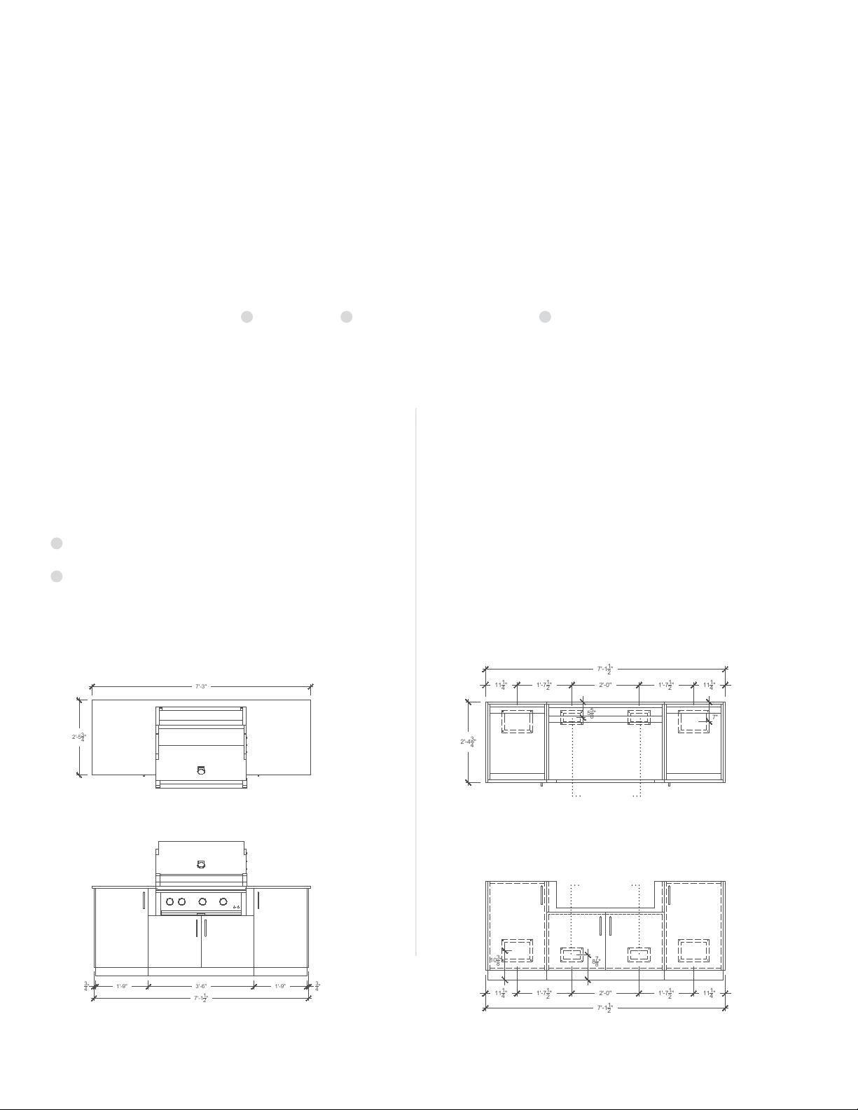
SIERRA 36
Specications
*Length 87”
*Depth 29
Height 36
1/2
3/4
”
± 1”
*Includes countertop nosing.
Components
Utility Cabinet (21”)
1
Universal track system.
2
Grill Base Cabinet (42”)
For integration with a 36” built-in grill.
Top View
1
2 1
Gas and Electrical Conduits Access PointsDimensions
Gas and electric lines can easily be run in and out of
the kitchen using the removable access panels located
in the bottom and back of each cabinet. To run lines
from cabinet to cabinet, use the circular conduit holes
located at the top and bottom of each side.
PLEASE ENSURE THAT ALL GAS, PLUMBING AND
ELECTRICAL WORKS ARE TO CODE BY USING A
LICENSED CONTRACTOR.
Top View
*
*
*INCLUDES COUNTERTOP NOSING
Front ViewFront View
Grill access for
electrical and gas
Grill access for
electrical and gas
3
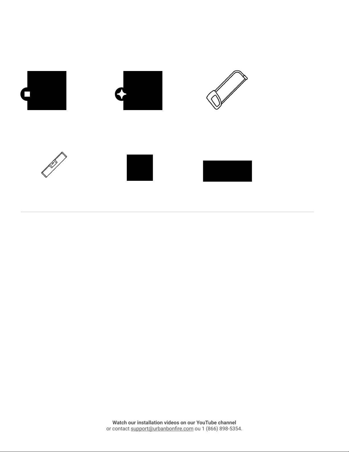
Tools Required
Watch our installation videos on our YouTube channel
or contact support@urbanbonre.com ou 1 (866) 898-5354.
Robertson #2 screwdriver
and/or drill bit
Level Clear Silicone Wood Shim
Items Provided
#8 screws
Phillips #2 head screwdriver
and/or drill bit
2” 8-32 Bolts
Metal Hacksaw 3/8 Wrench
Nuts
Leg wrench Toe kick clips
Installation videos
YouTube channel
4
Installation Protocol
Watch our installation videos on our YouTube channel
or contact support@urbanbonre.com ou 1 (866) 898-5354.
1. Measure out installation area and mark kitchen location.
2. Remove all internal components and place cabinets upside down on a protected surface.
3. Locate boxes containing cabinet legs and toe kicks.
4. Attach legs to cabinets by screwing on clockwise.
5. Using #8 screws, install side panel sliding toe kicks to applicable end-cabinets.
Note: Do not overtighten. Keep tape on toe kick (see Fig. 1).
6. Using #8 screws, install back panel sliding toe kicks.
Note: Applicable only to cabinets with nished back-panels. Do not overtighten. Keep tape on
toe kick (see Fig. 1).
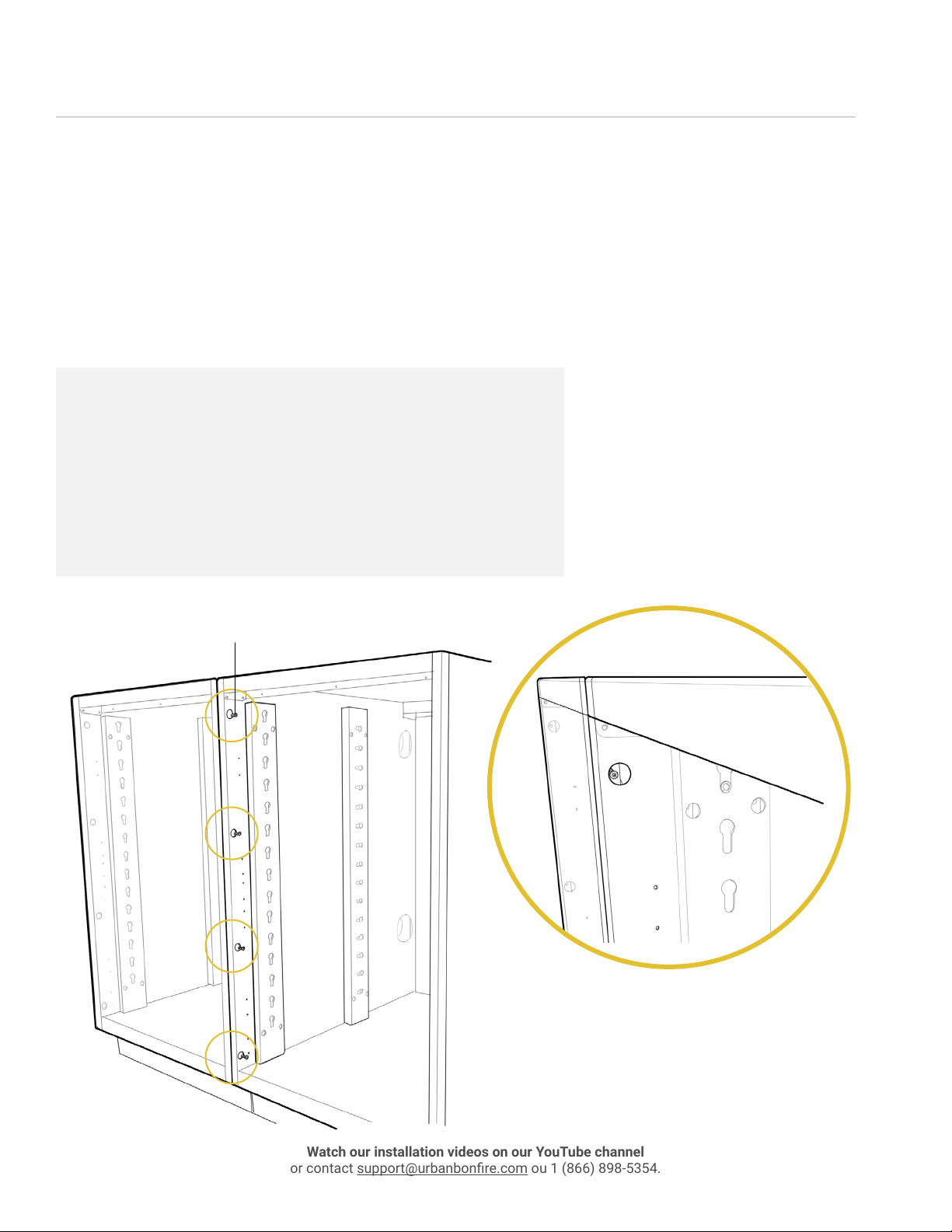
Fig. 1 - Self Leveling Toe Kick Assembly - BACK AND SIDE
Back and end nish panel toe kick assemblies are
attached to nish panel with 3, #8 screws (supplied). First
fasten the xed portion of the assembly and then slide
the self leveling portion into position. Use tape to hold self
leveling portion in place.
#8 screw
5
7. Place cabinets right side up so that they are standing on their legs.
Watch our installation videos on our YouTube channel
or contact support@urbanbonre.com ou 1 (866) 898-5354.
8. Align cabinets into the kitchen location and attach them together using #8 screws in the
front (see Fig. 2) and 2” long 8-32 bolts in the back (see Fig. 3).
Note: Cabinets without nished back panels are to be attached through the back section of
the cabinet (see Fig. 3). Cabinets with nished back panels are to be attached through the
holes on the inside of the cabinet. Do not overtighten.
Fig. 2 - Connecting Cabinets FRONTS
- Align and level cabinets
- Use 4, #8 screws (supplied) to
connect the cabinet fronts. DO NOT OVER TORQUE
WARNING: In high wind areas, cabinets should be
fastened to a xed structure.
#8 screw
6
 Loading...