

Installation Guide
KoldLok® 24” Extended
Raised Floor Grommet
Part Numbers
3” x 24” - 10012
6” x 24” - 10013
Table of Contents
Preparation Required for Installation Page 2
Tools and Product Components Page 2
Installation Procedures Page 3 & 4
Modications to Product Page 5
General Information Page 6
Warranty Page 7
Each carton contains the following items:
KoldLok Extended Raised Floor Grommets (10)
End Cap Sets—Left and Right Sides (10)
Adhesive Mounting Kit (10)
Self-Tapping #10 Screws (50)
Installation Guide (1)
Designer & Manufacturer
(888) 982-7800 www.upsite.com
1
Designer & Manufacturer
(888) 982-7800 www.upsite.com
Tools and Preparation Required for Installation
Tools Required:
• Bandsaw, table saw, or other appropriate cutting tool
• Hand tools, including bolt cutters, pliers, hammer (or mallet), stake, and metal le
Dimensions and Cutting Requirements Inches (W x D) Millimeters (W x D)
Item No. 10012 3”x 24” - Overall size 24” x 5.05” 610 x 128mm
Maximum cutout size sealed 24” x 4” 610 x 102mm
Usable cable area 22” x 2.5” 559 x 64mm
Product height above the raised oor 1” w/ mounting kit
Item No. 10013 6”x 24” - Overall size 24” x 8.08” 610 x 205mm
Maximum cutout size sealed 24” x 7” 610 x 178mm
Usable cable area 22” x 5.5” 559 x 140mm
Product height above the raised oor 1” w/ mounting kit
installed
installed
Preparation:
25mm w/ mounting kit
installed
25mm w/ mounting kit
installed
• Remove skirts and tip plates to access the cable cutout.
• Determine the maximum dimensions of the trimmed cutout. To ensure stability and
proper sealing, the KoldLok Extended Raised Floor Grommet should have a minimum
surface-to-oor contact of 1 inch (25mm) on three sides of the cutout. Otherwise, the
Grommet cannot be used to effectively seal the cutout. Contact Upsite Technologies,
Inc. at (888) 982-7800 for customized products and installation services designed to seal
larger openings.
• Determine whether to install Grommets by screwing the product directly to the oor
with the self-tapping screws or by using the Adhesive Mounting Kit.
• Clean the tile and bottom surface of the KoldLok Extended Raised Floor Grommet using
an alcohol wipe or a clean cotton cloth, damp with a solution of at least 50 percent
isopropyl alcohol. Helpful tip: When choosing your cleaning cloth, do not use fabric or
paper that will disintegrate or leave particles that could interfere with the adhesive.
• The KoldLok Extended Raised Floor Grommet can be modied to t special situations.
Designer & Manufacturer
(888) 982-7800 www.upsite.com
2
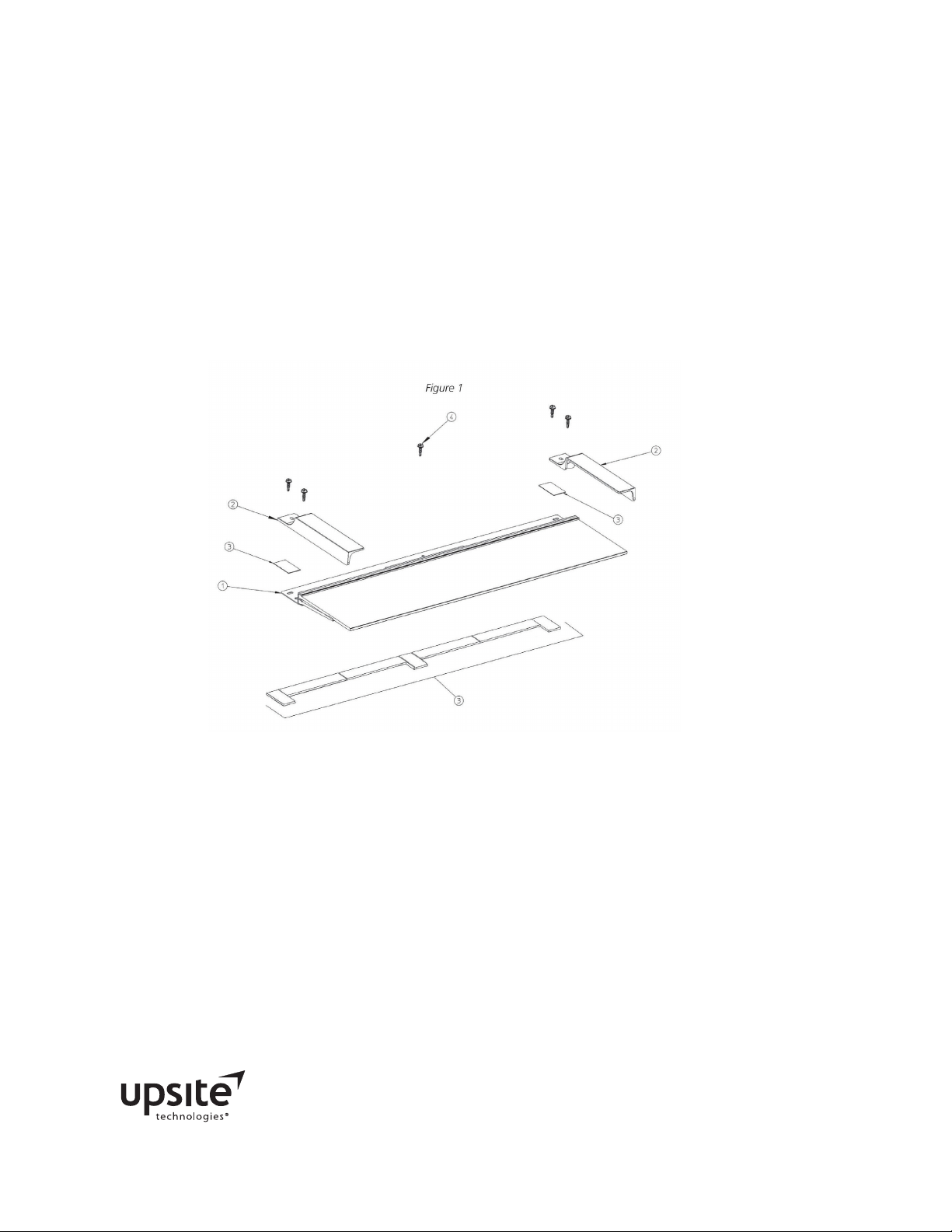
Product Components (see Figure 1)
1. KoldLok Extended Raised Floor Grommet.
2. Right and Left End Caps for protecting and sealing the end of the Grommet.
3. Adhesive Mounting Kit provided as an alternative mounting method if screws cannot be
used. The kit includes seven foam strips with 2-sided adhesive backing to adhere the
Grommet to the oor and two strips of double-sided adhesive tape to mount the End
Caps to the Grommet.
4. Self-Tapping Screws are provided as the preferred method of securing the Grommet to
the oor tile.
Installation Procedure with Self-Tapping Screws:
*IMPORTANT: If the KoldLok Extended Raised Floor Grommets are being installed in an active data
center, remove the oor tile and install the Grommet outside of the active data center environment.
Following installation, return the oor tile and Grommet to the data center.
1. Position the Grommet over the cable cutout, with the ange resting on the oor tile and
Grommet laments covering the cutout.
2. Ensure the ange does not rest on top of any cutout trim. If the Grommet cannot be
placed without resting on the cutout trim, install the Grommet with the Adhesive
Mounting Kit. See Installation Procedure with Adhesive Mounting Kit on Page 4.
3. Once the Grommet is positioned as desired, drive a self-tapping screw through the cen-
ter pre-drilled screw hole on the Grommet ange to attach the Grommet to the raised
oor.
Designer & Manufacturer
(888) 982-7800 www.upsite.com
3

Designer & Manufacturer
(888) 982-7800 www.upsite.com
Installation Procedure with Self-Tapping Screws Continued:
4. Align the screw holes of one End Cap with the screw holes on the end of the Grommet
ange. Use self-tapping screws to attach the End Cap and ange to the oor tile. The
screw-hole design allows for horizontal and vertical positioning of the End Caps when
attaching to the ange. NOTE: With the inside wall of the End Caps mounted against the
ange, the installed Grommet can seal an opening the length of a 600mm oor tile. With
the End Caps extended away from the ange, the installed Grommet can seal an opening
the length of a 24-inch oor tile.
5. Repeat Step 4 with the other End Cap.
6. Attach the Grommet with the remaining screws.
7. Clean any residue that may have been created during installation.
Installation Procedure with Adhesive Mounting Kit (see Figure 2):
1. Remove one layer of adhesive backing from each of the three pads and mount on the bot-
tom of the ange at the center and outside corners in a vertical position.
2. Remove one layer of adhesive backing from each of the four 5-inch strips. Mount strips
between each vertical pad, along the rear edge of the ange that is furthest away from
the brush holders.
3. Remove the second layer of adhesive backing from all seven adhesive strips. Position the
Grommet on the oor tile and over the cable cutout.
4. Adhere the unit to the oor. Press down rmly on all portions of the unit to ensure a se-
cure connection to the raised oor surface.
5. Use the two strips of thin double-sided adhesive to adhere the left and right End Caps to
the top of the ange.
6. Mount the End Cap
Figure 2: Assembled Adhesive Mounting Kit
Designer & Manufacturer
(888) 982-7800 www.upsite.com
4

Modication of Extended
Raised Floor Grommets
The KoldLok Extended Raised Floor Grommets can be modi-
ed to seal large and unique openings. The metal lament
channel and Grommet ange may be cut to a desired length.
*IMPORTANT: Never cut metal within the raised oor environ-
ment.
1. Using a hammer (or mallet) and stake, drive one of the
metal lament channels out of the Grommet ange to
the desired length.
2. Mark the desired cut line.
Step 1
3. Use bolt cutters to cut and snap the metal lament
channel.
4. Crimp the ends of the metal lament channel with pliers
to prevent bristle escape. File any rough or sharp corners
and edges
5. Repeat Steps 1 through 5 for the other metal lament
channel.
6. Mark the empty Grommet ange for cutting. Cut the
ange with a saw.
7. File the cut edge of the ange.
8. Use a hammer (or mallet) and stake to reposition the
metal lament channel in the Grommet so that the end
of the metal lament channel does not protrude from
the end of the ange channel.
Step 3
Step 6
Designer & Manufacturer
(888) 982-7800 www.upsite.com
5

Designer & Manufacturer
(888) 982-7800 www.upsite.com
Installation Guide
KoldLok® 24” Extended Raised Floor Grommet
General Information
Effective Installation of Cables
In order to minimize any air loss from under the raised-oor plenum, allow for adequate
slack in the cables. If the cables are under too much tension, the Grommet laments may
be pulled apart, resulting in a V-shaped gap that will cause an increase in the volume of air
escaping from under the raised oor.
Cutting Raised Floor Tiles
Each raised oor tile manufacturer provides instructions to properly and safely modify their
products. Installers must be familiar with and observe tile manufacturer’s recommendatios
with regard to applicable tools, cutting procedures, the design load capacity of the cut tile,
and any additional underoor support requirements for cut raised oor tiles.
When installing the KoldLok Extended Raised Floor Grommet on a newly cut hole, trim
the cutout prior to installation.
Maintaining Proper Cooling of Equipment
Failure to follow computer manufacturer’s guidelines for maintaining proper cooling may
result in the overheating of equipment. Before sealing gaps between racks, ensure that
there is adequate airow to the intake side of the computer equipment or cabinets through
devices such as perforated oor tiles or grates. Achieving proper airow to the intake side of
computer equipment and/or cabinets is the responsibility of the customer.
Safety Requirements
Installers must be familiar with standard safety and risk management practices when work-
ing on server rack equipment or in data center environments.
Customer Support
If you have any questions, please
contact us direct at (505) 798-0200,
or Toll Free at (888) 982-7800
Email us at info@upsite.com
P/N 60227 Rev. A © 2012
Designer & Manufacturer
(888) 982-7800 www.upsite.com
6

Limited Warranty
KoldLok® 24” Extended Raised Floor Grommet
Upsite Technologies, Inc. (the Company) warrants to the original purchaser that products delivered
hereunder will be free of defects in materials and workmanship for a period of twelve (12) months
from the date of purchase (the “Warranty Period”).
The Company shall, at its option, within the Warranty Period, either repair or replace free of charge,
any product or part thereof found, upon the Company’s inspection, to be defective in materials and
workmanship, and will return the repaired or replaced product to the purchaser at Company’s expense.
For warranty service and shipping instructions, contact the Company at the telephone number shown
below. If the product is under warranty and the defect appears to be covered by this Limited Warranty, the Company will issue to the purchaser a Notice of Authorization For Warranty Return. Products
returned to the Company for warranty service must be accompanied by a statement of defect, the
Notice of Authorization for Warranty Return provided by the Company, and proof of purchase.
This Limited Warranty is conditioned on the following:
1. The Company must be notied within 12 months of purchase and have been given the opportunity
of inspection by return of any alleged defective product free and clear of all liens and encumbrances to the Company or its manufacturer; and
2. The product must not have been abused, misused, or improperly maintained, and/or repaired during such period; and
3. Such defect has not been caused by corrosion or exposure to other than ordinary wear and tear.
The company makes no other express or implied warranty or representation of any kind whatsoev-
er including any warranty of merchantability or tness for a particular purpose and all such other
warranties are hereby included.
The Company’s maximum liability hereunder is limited to the purchase price of the product. In no
event shall the Company be liable for any consequential, indirect, incidental, or special damages of
any nature arising from the sale or use of the product, whether based in contract, tort, strict liability,
or otherwise.
Note: Some jurisdictions do not allow limitations on incidental or consequential damages or how long
an implied warranty lasts, so that the above limitations may not fully apply. This warranty gives specic legal rights and you may also have other rights which may vary from jurisdiction to jurisdiction.
For complete warranty and repair information Call (888) 982-7800 or visit upsite.com
Register your product online at www.upsite.com/warranty to initiate your warranty.
U.S. Patent No. 6,632,999 and International Patents Pending
Designer & Manufacturer
(888) 982-7800 www.upsite.com
7
 Loading...