

USER MANUAL
Queen Star Series Online UPS 6K-20KVA

1
Contents
1. Brief introduction.......................................................................1-6
1.1 System and model description.............................................................1
1.2 Description of commonly used symbols.............................................2
1.3 Appearance.......................................................................................2-5
1.4 Product specification and performance............................................5-6
2. Safety Instruction..........................................................................7
3. Installation................................................................................8-14
3.1 Unpacking and inspection...................................................................8
3.2 Input and output power wiring and protective earth ground
installation....................................................................................8-10
3.3 Operating procedure for connecting the long backup time model UPS
with the external battery.............................................................10-11
3.4 Parallel operation.........................................................................11-14
4. Operation and Operating mode............................................15-22
4.1 Operation......................................................................................15-16
4.2 Operating mode............................................................................16-22
5. Battery maintenance...................................................................23
6. Notes for battery disposal and battery replacement................24
7. Troubleshooting.....................................................................25-26
Appendix 1 Description of Display panel.................................27-28
Appendix2 Indicator and alarm...............................................29-30
8. Chapter Operation (LCD model) ........................................31-42
8.1 Operation Display Panel....................................................................31
8.2 Operation Mode...........................................................................32-36
8.3 Operating Instructions..................................................................36-38
8.4 Checking UPS function.....................................................................38
8.5 Setting the output voltage and frequency.....................................38-39
8.6 Troubleshooting...........................................................................39-42

2
1. Brief introduction
1.1 System and model description
The On-Line-Series is an uninterruptible power supply incorporating
double-converter technology. It provides perfect protection specifically for
strict load. The double-converter principle eliminates all mains power
disturbances. A rectifier converts the alternating current from the socket
outlet to direct current. This direct current charges the batteries and powers
the inverter. In the event of power failure, the maintenance-free batteries
power the inverter. Thus the inverter generates a sine wave AC power,
which permanently supplies the loads.
Designed with the proven on-line, double conversion architecture, this
series of UPS offers the greatest degree of availability in power protection
and provides continuous high-quality AC power to connect strict load,
especially for the basic equipments in some areas as: finance,
communication, government, traffic, manufacture, education and so on.
This manual is applicable to the following models:
Type Model Input Battery
Standard
Long back
up time
6KVA 6K Single phase + N Inbuilt
10KVA 10K Single phase + N Inbuilt
6KVAL 6KL Single phase + N External battery bank
10KVAL 10KL Single phase + N External battery bank
10KVAL 31 10KL Thr ee-phase + N + PE External battery bank
12KVAL 31 12KL Thr ee-phase + N + PE External battery bank
15KVAL 31 15KL Thr ee-phase + N + PE External battery bank
20KVAL 31 20KL Thr ee-phase + N + PE External battery bank
3
Alert you to pay special
Do not dispose w
ith
1. Brief introduction
1.2 Description of commonly used symbols
The following symbols will be used in this manual and may appear during
the course of your practical applications. Therefore, all users should be
familiar with them and understand their meanings.
Notation and Explanation
Notation
Caution of high voltage
Idle or shut down the UPS
Alternating current source (AC)
Direct current source (DC)
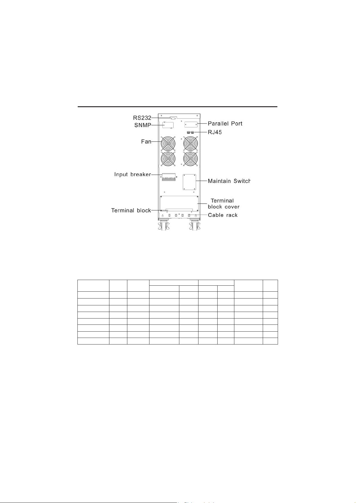
1.3 Appearance
Explanation Notation
attention
Turn on the UPS
Turn off the UPS
Explanation
Protective ground
Alarm silence
Overload indication
Battery check
Recyclable
ordinary trash
Battery
4
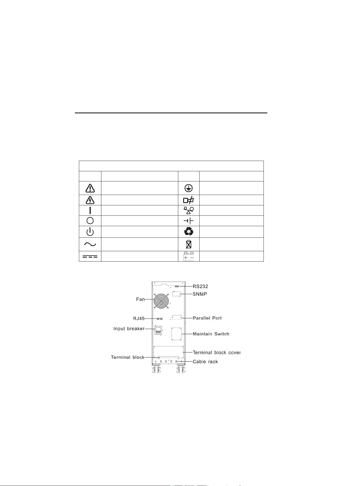
BACK VIEW OF 6K
1. Brief introduction
BACK VIEW OF 6KL
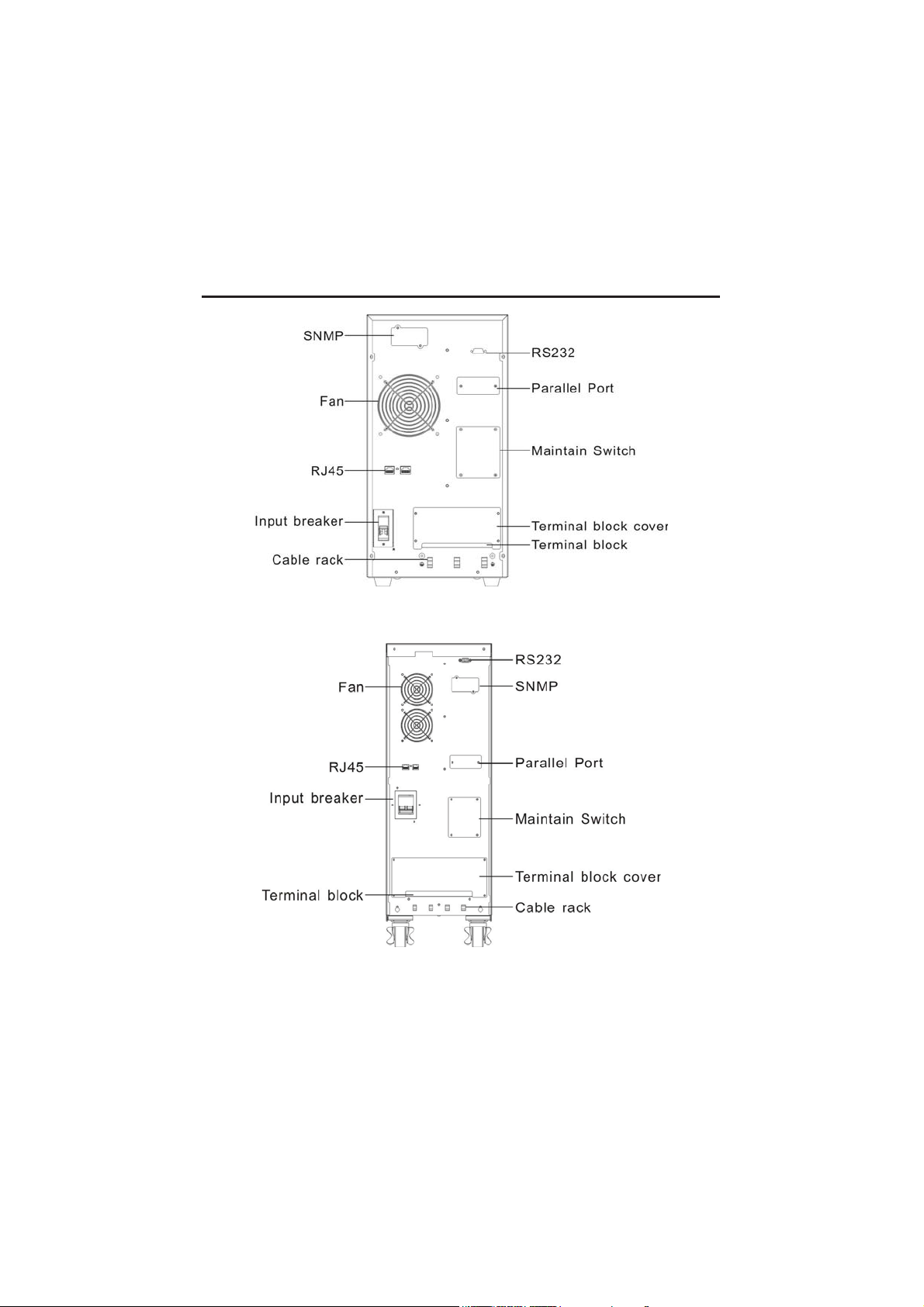
BACK VIEW OF 10K
5
1. Brief introduction
BACK VIEW OF 10KL
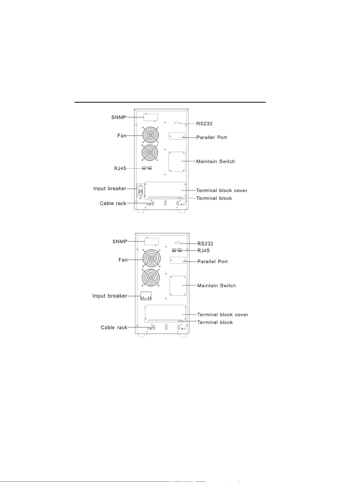
BACK VIEW OF 31 10KL
6
1. Brief introduction
BACK VIEW OF 31 12KL/31 15KL/31 20KL
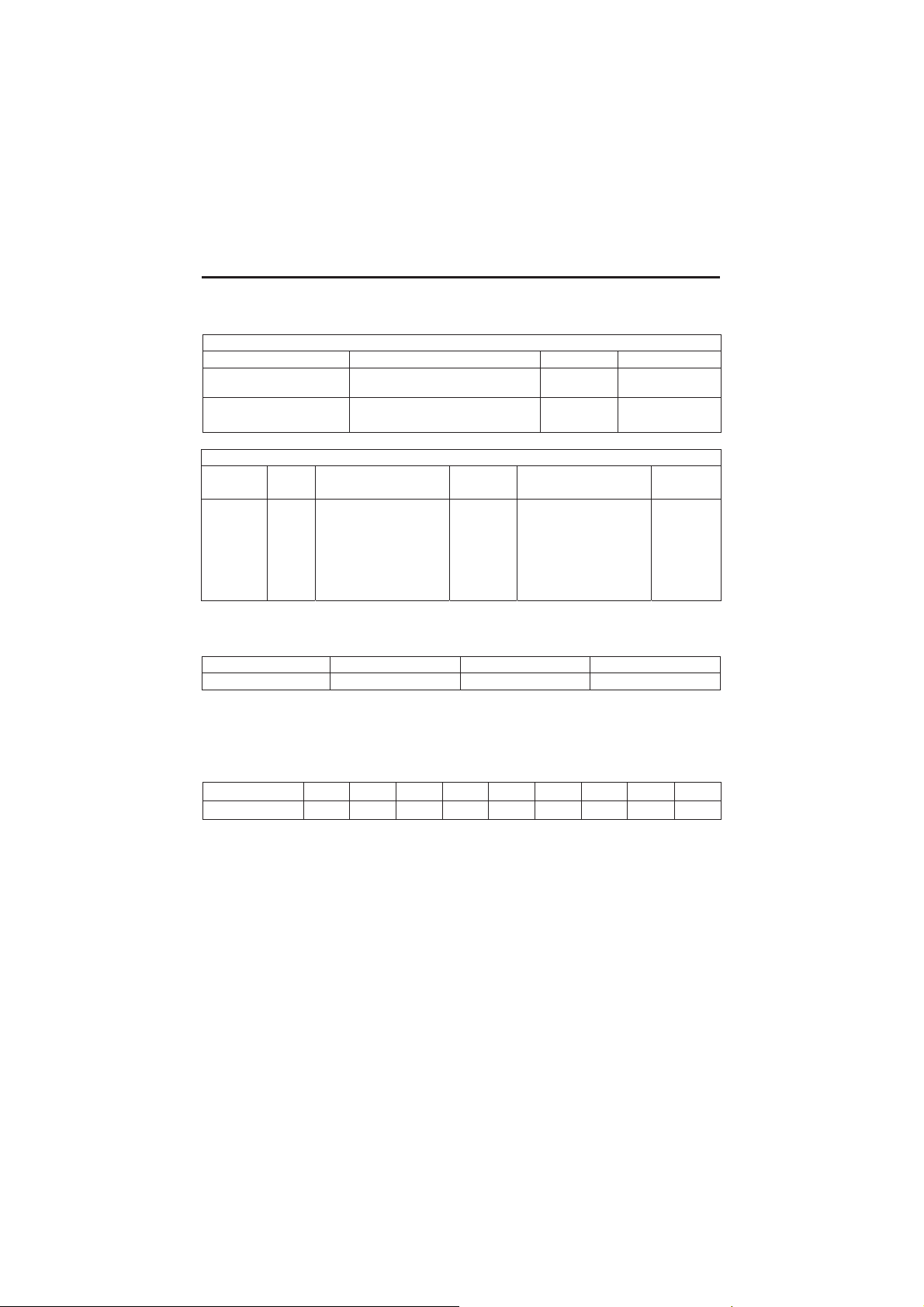
1.4 Product specification and performance
●General specification
Power Rating Model
6KVA/4.8KW 6K 50
6KVA/4.8KW 6KL 50
10KVA/8KW 10K 50
10KVA/8KW 10KL 50
10KVA/8KW 31 10KL 50
12KVA/9.6KW 31 12KL 50
15KVA/12KW 31 15KL 50
20KVA/16KW 31 20KL 50
Frequency
(Hz)
Voltage (VAC) Current Voltage Current
Note: Output voltage can be set: 200V/208V/220V/230V/240V.
Frequency can be set as 60Hz.
Input Output
(120-274)
(120-274)
(120-274)
(120-274)
(120-274)
(120-274)
(120-274)
(120-274)
32Amax 220VAC 27A 560x260x717 61.5
32Amax 220VAC 27A 533x260x501 21
50Amax
50Amax
50Amax 220VAC 45A 533x260x501 24
80Amax 220VAC 54A 560x260x717 39.5
80Amax
100Amax 220VAC 91A 560x260x717 39.5
Dimensions
(L*W*H)mm
220VAC 45A 560x260x717 67.5
220VAC 45A 533x260x501 23
220VAC 68A 560x260x717 39.5
Weight
(kg)
7
1. Brief introduction
Current
●Electrical performance
Model Voltage Frequency Power Factor
6K(L)/10K(L) Single-phase(220VAC/230VAC)
31 10KL/31 12KL/
31 15KL/31 20KL
Voltage
regulation
±1% 0.8 lag
Power
factor
Three-phase (380VAC/220VAC、
380VAC/230VAC)
Frequency Distortion Overload capacity
Line mode:
(1)、Synchronized 46
~ 54Hz;
(2)、50Hz (Line 40~
46 and 54~ 60Hz)
Battery mode: 50Hz
Input
Output
THD<2%
Full load
(Linear
load)
50/60Hz >0.99(Full load)
50/60Hz >0.95(Full load)
105%-125%load
transfers to bypass
mode after 1 minutes;
125-135% load
transfers to bypass
mode after 30second
crest ratio
3:1
maximum
●Operating environment
Temperature Humidity Altitude Storage temperature
0℃-40℃ <95% <1000m 0℃-40℃
Note: If the UPS is installed or used in a place whe re the altitude is above
than 1000m, the output power must be decrease in use, please refer to
the following:
Altitude(M) 1000 1500 2000 2500 3000 3500 4000 4500 5000
Load 100% 95% 91% 86% 82% 78% 74% 70% 67%

8
2. Safety Instruction
● Even if the interruptible Power System (UPS) is not connected to utility
power, the output socket of the UPS may still present 220V/230V output
voltage.
● If it is necessary to replace the external battery cord or power cord, please
purchase the original material from the service center or distributor of
our company so as to avoid overheat or spark resulting in fire due to
insufficient capacity.
● Do not let battery or batteries get close to any heating source and do not
incinerate battery or batteries, they may explode.
● Do not open or mutilate the battery or batteries, released electrolyte is
highly poisonous and harmful to the skin and eyes.
● Do not short the positive and negative of battery electrode. Otherwise, it
may cause electric shock or fire.
● To avoid the risk of being shocked, please do not attempt to open the
case of the UPS.
● A battery can present a risk of electric shock and high short circuit
current.
● Do not plug household appliance such as hair dryers to UPS.

9
3. Installation
3.1 Unpacking and inspection
1) Unpack the packaging and check the package contents. The shipping
package contains:
● A UPS
● A user manual
● A communication cable
2) Inspect the appearance of the UPS to see if there is any damage during
transportation. Do not turn on the unit and notify the carrier and dealer
immediately if there is any damage or lacking of some parts.
3.2 Input and output power wiring and protective earth ground
installation
3.2.1 Notes for installation
1) The UPS must be installed in a location with good ventilation, far away
from water, inflammable gas and corrosive agents.
2) The UPS should not be tilted. The air inlet port at the lower part of the
front panel and the fan outlet port on the rear panel should not be
blocked so as to ensure good ventilation (Allow at least 0.5m of space on
each side).
3) In case if the UPS is unpacked, installed and used at very low
temperatures, condensation of water drops may appear. It is necessary
to wait until the UPS is fully dried inside out before proceeding to
installation and use. Otherwise, there may be a risk of electric shock.
3.2.2 Installation
Installation and wiring must be performed in accordance with the local
electric code and the following instructions by professional personnel. For
safety, please cut off the mains power breaker before installation. The
battery breaker also needs to be cut off if it is a long backup time model.
1) Open the terminal block cover located on the rear panel of the UPS
(please refer to the appearance diagram).
2) For 6K(L) UPS, it is recommended to select the UL1015 10AWG (6mm
wire or other insulated wire which complies with AWG Standard for
the UPS input and output wirings.
2
)

10
3. Installation
3) For 10K(L)/31 10KL UPS, it is recommended to select the UL1015
8AWG (10 mm2) wire or other insulated wire which complies with
AWG Standard for the UPS input and output wirings.
4) For 31 12KL/31 15KL/31 20KL UPS, it is recommended to select the
UL1015 6AWG (25mm2) wire or other insulated wire which complies
with AWG Standard for the UPS input and output wirings.
Note: Do not use the wall receptacle as the input power source for the
UPS, as its rated current is less than the UPS’s maximum input
current. Otherwise the receptacle may be burned and destroyed.
(Please refer to section 1.4)
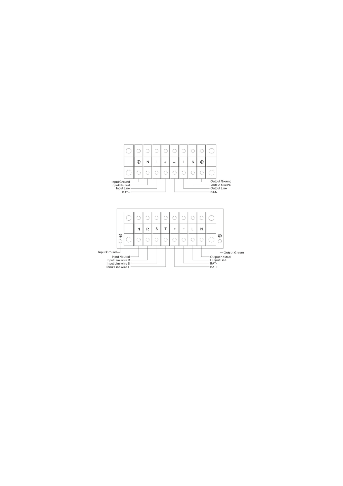
5) Connect the input and output wires to the corresponding input and output
terminals according to the following diagram.
Note: You must make sure that the input and output wires and the input and
output terminals are connected tightly.
6) The protective earth ground wire refers to the wire connection between
the equipment which consumes electro-equipment and the ground wire.
The wire diameter of protective earth ground wire should be at least as
above mentioned for each model and green wire or green wire with
yellow ribbon wire is used.
7) After having completed the installation, make sure the wiring is correct.
8) Please install the leak current protective breaker at the output power
distribution panel of the UPS if necessary.
9) To connect the load with the UPS, please turn off all the loads first, then
perform the connection and finally turn on the loads one by one.
10) No matter the UPS is connected to the utility power or not, the output
of the UPS may have electricity. The parts inside the unit may still have
hazardous voltage after turning off the UPS. To make the UPS have no
output, power off the UPS, and then disconnect the utility power
supply.
11) Suggest charging the batteries for 8 hours before use. After connection,
turn the input breaker in the “ON” position, the UPS will charge the
batteries automatically. You can also use the UPS immediately without
charging the batteries first, but the backup time may be less than the
standard value.
11
3. Installation
12) If it is necessary to connect the inductance load such as a monitor or a
laser printer to the UPS, the start-up power should be used for
calculating the capacity of the UPS, as its start-up power consumption
is too big when it is started.
Input and Output Terminal Block wiring diagram of 6K(L)/10K(L)
Input and Output Terminal Block wiring diagram of
31 10KL/31 12KL/31 15KL/31 20KL
3.3 Operating procedure for connecting the long backup time
model UPS with the external battery
3.3.1 The nominal DC voltage of external battery pack is 192VDC. Each
battery pack consists of 16 pieces of 12V “maintenance-free” batteries in
series. To achieve longer backup time, it is possible to connect
multi-battery packs, but the principle of “same voltage, same type” should
be strictly followed.
3.3.2 For 6KL/10KL/31 10KL/31 12KL/31 15KL/31 20KL, the procedure
of installing battery bank should be complied with strictly. Otherwise you
may encounter the hazardous of electric shock.

12
3. Installation
1) A DC breaker must be connected between the battery pack and the
UPS. The capacity of breaker must be not less than the data specified
in the general specification as follow.
Model 6K 6KL 10K 10KL 31 10KL 31 12KL 31 15KL 31 20KL
Battery
voltage
Battery
current
Note: 240VDC battery voltage can be choose for 6K(L)/10K(L).
192VDC 192VDC 192VDC 192VDC
34A max. 34A max. 56A max. 56A max.
192VDC
56A max. 62A max. 78A max. 104A max.
192VDC 192VDC
192VDC
2) Set the battery pack breaker in “OFF” position and connect the 16
pieces of batteries in series.
3.3.3 To complete the connection by plugging the connector of the external
battery cable into the external battery socket of the UPS. Do not attempt to
connect any loads to the UPS now. You should connect the input power
wire to the right position first. And then set the breaker of the battery pack
in the “ON” position. After that set the input breaker in the “ON” position.
The UPS begins to charge the battery packs at the time.
3.4 Parallel operation
3.4.1 Brief introduction of the redundancy
N+X is currently the most reliable power supply structure. N represents the
minimum UPS number that the total load needs; X represents the redundant
UPS number, i.e. the fault UPS number that the system can handle
simultaneously. The bigger the X is, the higher reliability of the power
system is. For occasions where reliability is highly required, N+X is the
optimal mode. As long as the UPS is equipped with parallel cables, up to 3
of them can be connected in parallel to realize output power sharing and
power redundancy.
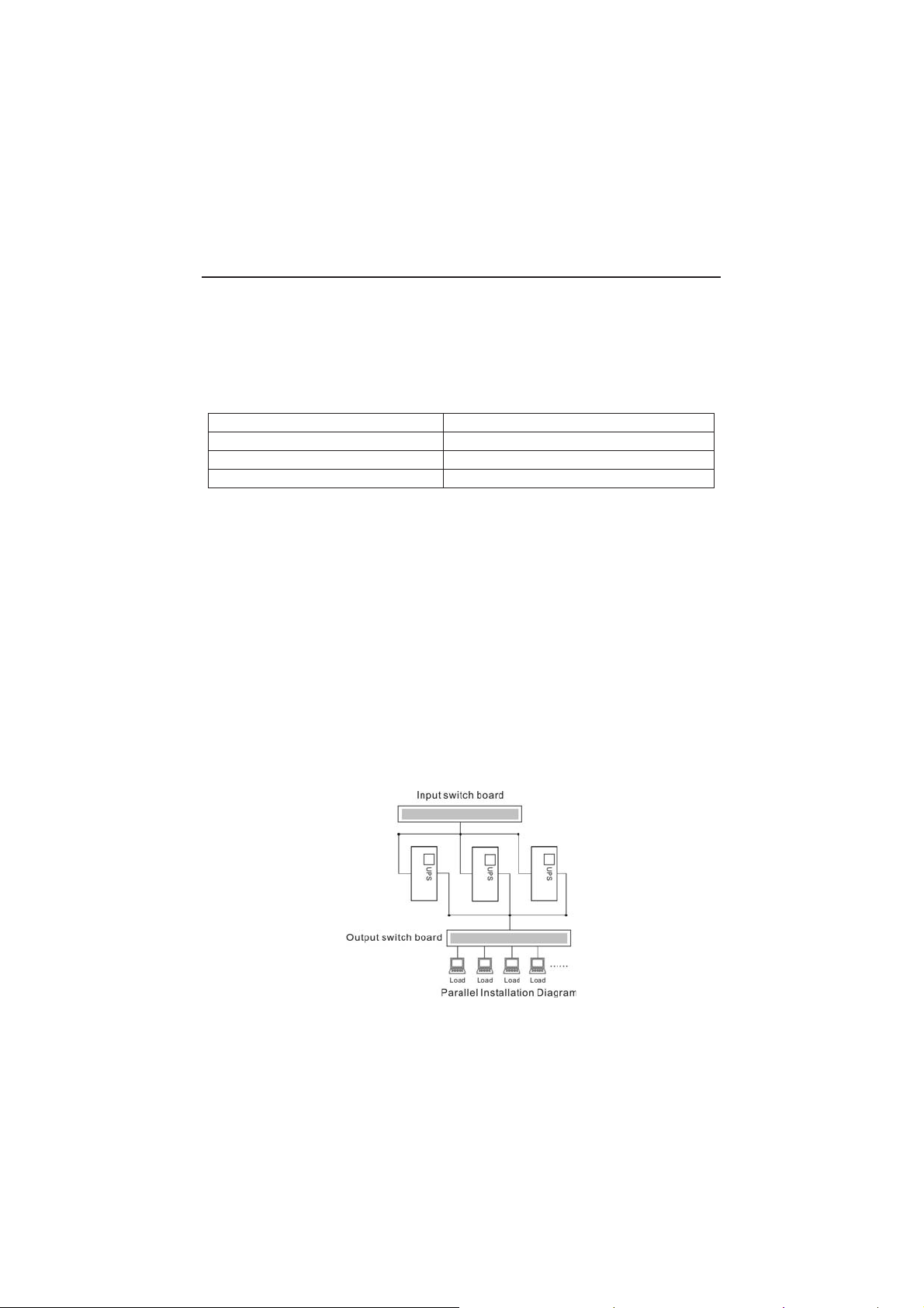
3.4.2 Parallel installation
1) Users need to opt a standard 25-pin communication cable, which should
have 25 cores, corresponding stitches and shield, as the UPS parallel
cable. The length of the parallel cable is appropriate to be less than 3 m.
2) Strictly follow the stand-alone wiring requirement to perform the input
wiring of each UPS.
13
3. Installation
Model No.
Capa
city of breaker
6K(L)
≥40A/250VAC
10K(L)/3
1
10KL
≥60A/250VAC
31 12KL /31
15KL/3
1
20KL
≥100A/250VAC
3) Connect the output wires of each UPS to an output breaker panel first,
and then connect the wiring to the load via the breaker panel.
4) The parallel UPS must be equipped with battery individually.
5) Please refer the figure followed to see the wiring of parallel operation.
The capacity of the breaker must be not less than the specification as
follow.
*The requirement of the output wiring is as follows:
●When the distance between the UPSs in parallel and the breaker panel is
less than 20 meters, the difference between the wires of input & output
of the UPSs is required to be less than 20%;
●When the distance between the UPSs in parallel and the breaker panel is
greater than 20 meters, the difference between the wires of input &
output of the UPSs is required to be less than 10%.
3.4.3 Operation and maintenance
1) To perform the general operation, follow the stand-alone operating
requirement.
2) Start up: The units transfer to INV mode simultaneously as they start up
sequentially in utility power mode.
Shutdown: the units shut down sequentially in INV mode. When the last
one completes the shutdown action, each unit will shut down the inverter
simultaneously and transfer to bypass mode.
3) To perform the maintenance, follow the stand-alone requirement.
 Loading...