

3Phase HF UPS 10-120kva USER Manual
Page1
User Manual
ES33 Series Online HF UPS10-120kva
(380/400/415Vac)

3Phase HF UPS 10-120kva USER Manual
Page2
Contents
Section I: PW series Product System Overview ................................................................................. 3
1.1 Introduction ........................................................................................................................... 3
1.2 PW Series product features .................................................................................................. 4
1.2.1 Product specific parameters ........................................................................................ 4
Section II Installation of Single Machine System ............................................................................... 7
2.1 Introduction ........................................................................................................................... 7
2.2 Inspecting and Unpacking the UPS Cabinet ....................................................................... 7
2.3 Storage .................................................................................................................................... 8
2.4 Link (Connection) ................................................................................................................. 8
2.4.1 Incoming mode ............................................................................................................. 9
2.4.2 Power cable ................................................................................................................... 9
2.5 Control cable and communication ..................................................................................... 10
2.5.1 Features of the monitoring panel .............................................................................. 10
2.5.1Input interface of emergency power off .................................................................... 10
2.5.3 Temperature detection interface of the external battery ........................................ 11
2.5.4 Serial port RS232 ....................................................................................................... 12
2.5.5 SNMP card interface .................................................................................................. 12
Section III: Installation of Battery..................................................................................................... 13
3.1 Introduction ......................................................................................................................... 13
3.2 Safety .................................................................................................................................... 13
3.3 Battery cabinet .................................................................................................................... 14
3.3.1 Introduction ............................................................................................................. 14
3.3.2 Environmental temperature ................................................................................... 14
3.3.3 Temperature pickup of battery .............................................................................. 15
3.3.4 Cable incoming ......................................................................................................... 15
3.3.5 Structural map of battery configuration ................................................................ 15
Note: Please pay high attention to the battery connection ,regarding the Negative Pole”-“ ,
the Positive Pole”+” and the Neutral”N”,. ............................................................................ 15
(1) Standard model with internal battery. .................................................................. 15
Please refer the below sketch Diagram 17-1 ...................................................................... 15
3.4 Power cable of battery .......................................................................................................... 16
3.4.1 Installation of battery ................................................................................................ 16
3.4.2 Battery connection .................................................................................................. 17
Section IV Installation of Parallel System ......................................................................................... 17
4.1UPS single machine of parallel system ................................................................................ 17
4.2 Hot backup system ................................................................................................................ 19
Section V: Installation Diagram ......................................................................................................... 21
5.1 External structure ................................................................................................................. 21
5.2 Internal view ........................................................................................................................ 21
Section VI: Operation Procedure ...................................................................................................... 23
Section VII: Operational & Controlling Display Panel ................................................................... 25
7.1Introduction ........................................................................................................................... 25
7.1.1 LCD and menu key ................................................................................................. 27
7.1.2 Parameter Setting .................................................................................................... 28

3Phase HF UPS 10-120kva USER Manual
Page3
Section I: PW series Product System Overview
1.1 Introduction
PW is a high-performance and fully digital UPS utilizing the double DSP control
technology with the power factor correction function. Its performance indexes reach the
leading level of the industry and the power grade contains 15-80 KVA. PW UPS is
connected between the commercial power and the important load to supply the
high-quality power to the load. It adopts the high-frequency double conversion pulse
width modulation(PWM) and fully digital control technology, the output voltage is not
influenced by the change and interference of the input voltage and frequency of the
utility.
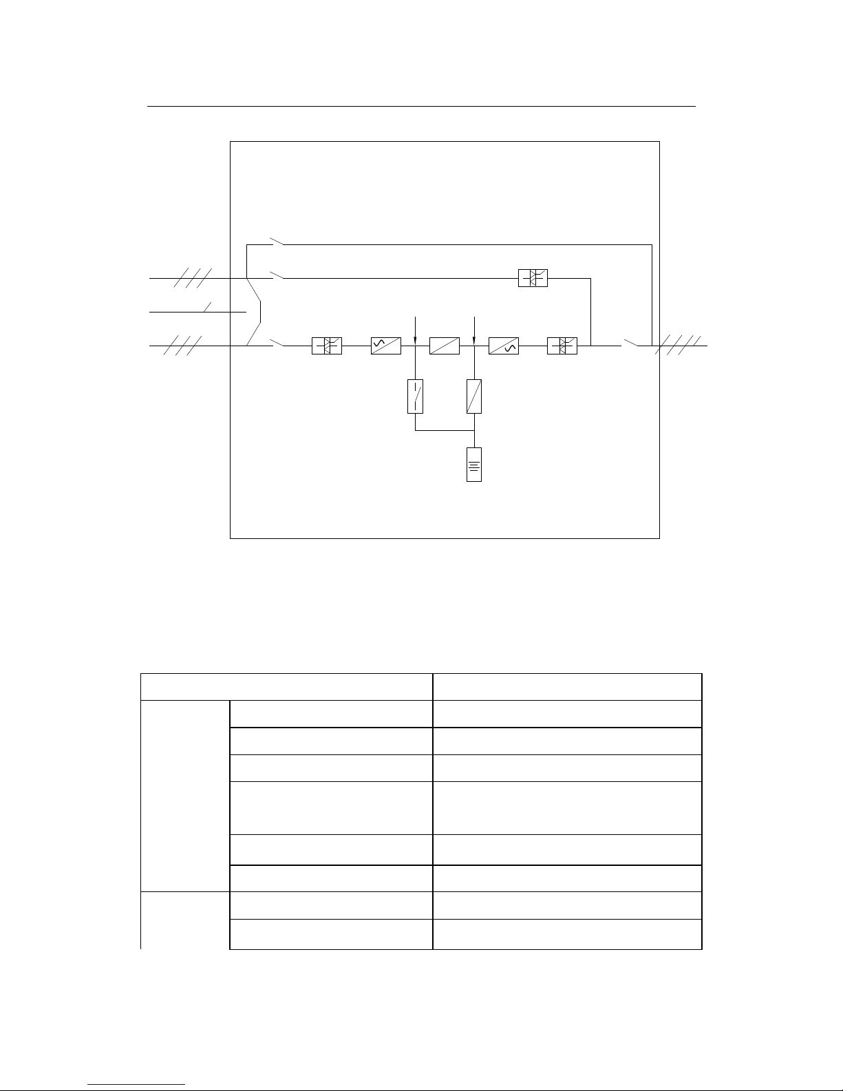
As shown in diagram 1, the utility is inputted from CB1, the rectifier converts the
utility to DC .The PFC converts the low DC to high DC ( DC busbar ) and supplies
power to the DC/DC battery charger (charge the battery at any time) and the inverter. The
inverter converts the DC power to AC power to supply the load. When the utility is
interrupted, the battery supplies the back-up power to the load through the battery switch,
PFC and inverter. When inverter is fault or overload time is finished, the external bypass
supplies power to the load through the input switch CB2 and static bypass. In addition,
for the maintenance and repair of the UPS, UPS will supply the power to the load through
the internal maintenance bypass. When the UPS is in normal mode, all switches are
closed except the maintenance bypass switch.
3Phase HF UPS 10-120kva USER Manual
Page4
Diagram 1, frame of the single machine system
1.2 PW Series product features
1.2.1 Product specific parameters
Figure 1: Performance parameters
Capacity
10,15,2
0,30,40,50,60,80
,100,120
kVA
Main input
I
nput voltage
380V/400/415V (line voltage
) Input mode
Three-phase
five-wire Power factor
>0.99
Total Harmonic Distortion,
Harmonic current
<3%
Voltage range
(
line voltage
)
–20%~+25%
Frequency range
40~
70HZ
Bypass
input
I
nput voltage
380V/400/415V (line voltage
) I
nput voltage
range
–15%~+25%( settable)

3Phase HF UPS 10-120kva USER Manual
Page5
Input mode
Three
-
phase
five-wire Frequency range
40~70HZ
(can be set)
Output
Steady
s
tate voltage precision
(balanced load)
±0.5%
Dynamic voltage transient
±2%(0~100% load variation)
V
oltage distortion
THDU
(linear load)
THD<0.5%
(phase voltage
) V
oltage distortion
THDU
(non-linear load)
THD<3%
(phase voltage
) Power factor
0.9 (lagging)
Frequency
t
racking
range
50/60
Hz±3Hz
Frequency precision
(battery
inversion)
±0.01%
Three-phase separation
120±0.5°
Frequency tracking rate
Adjustable
between
0.5Hz/s
and
5Hz/s
Inverter
overload capacity
105%<load<125% load, convert to bypass
output after 10min
125%< load, convert to bypass output
after 10S
>150% load, convert to bypass output
after 200ms
Load between 105%~150%, close the
inverter according to the overload curve
Bypass overload
capacity
125% load, run for a long time
125%<load< 150%, 10 mins
load>150%, 1s
Normal switching time
0
System
O
verall
w
orking efficiency
the maximum is
94%
ECO mode is 98%

3Phase HF UPS 10-120kva USER Manual
Page6
Display
LCD+LED
EMI
IEC62040
-2
EMS
IEC61000
-4-
2(ESD)
IEC61000-4-3(RS)
IEC6100-4-4(EFT)
IEC6100-4-5(Surge)
Noise (1m)
<58dB
Insulation resistance
>2M(500VDC)
Insulation strength
(Input and output ground)
2820Vdc
;
leakage current is lower than 3.5mA,
1min without flashover
Surge protection
Meet the Ⅳ installation location
requirement of IEC60664-1, that is, the
ability of bearing 1.2/50us+8/20us
combination wave is not lower than
6KV/3KA
Protection degree
IP20
Batte
ry number
32/36/38/40 cells of
12V battery
Installation
Connection mode
bottom incoming and outgoing

3Phase HF UPS 10-120kva USER Manual
Page7
Section II Installation of Single Machine System
2.1 Introduction
This section introduces the necessary UPS requirements of the UPS sitting and
routing.
Because each site possesses its particularity, this section does not introduce the
detailed installation steps but support the instructional general installation steps and
methods to the installation engineer. The installation engineer should handle according to
the specific situation of the site.
Notes:
Connect the UPS with the power after the agreement of the commissioning engineer.
The UPS installation should be implemented by the qualified engineer according to
the description of this section. All other equipment are not referred in this manual
will be accompanied by its detailed mechanical and electrical installation data when
shipping.
The standard PW UPS system can connect with the three-phase four-wire (earthing)
system TN,TT and IT alternating current power distribution network and support the
transformer optional parts of transferring three-wire to four-wire. If it used for the IT
alternating current power distribution network, a four-grade circuit breaker should be
equipped to the input referring to the relevant IT system standard.
Be careful to the installation of the battery. When connect the battery, the voltage of
the battery terminal will exceed 400Vdc, which possess mortal danger. Please wear
the eyes protecting cap to avoid the damage of the eyes from the accidental electric
arc. Take off the ring, watch and other metal adornment. Use the tool with the
insulated handle and wear the rubber glove. If the electrolyte of the battery leaks or
the battery is damaged, change the battery and put it in vessel with against sulphuric
acid. Handle it according to the local regulation. If the skin touches the electrolyte,
wash with water immediately.
2.2 Inspecting and Unpacking the UPS Cabinet
The cabinet is shipped bolted to a wooden pallet and protected with preservative bag.
The UPS cabinet is heavy. If unpacking instructions are not closely followed, the
cabinet may tip and cause serious injury.

3Phase HF UPS 10-120kva USER Manual
Page8
1. Carefully inspect the outer packaging for evidence of damage during transporation.
Do not install a damaged cabinet. Report any damage to the carrier and contact service
representative immediately.
2. Use a forklift or pallet jack to move the packaged cabinet to the installation site,
before unpacking. Insert the forklift or pallet jack’s forks between the pallet supports
and the bottom of the unit. Do not tilt the UPS cabinet more than 10° from vertical or the
cabinet may tip over.
3. Set the pallet on a firm, level surface, allowing a minimum clearance of 3m (10 ft)
on each side for removing the cabinet from the pallet.
4. Remove the protective covering from the cabinet.
5. Remove the packing material, and dispose them in a responsible manner.
6. Visual inspection: whether there is any transporting damage happened to the UPS,
including the internal and external of the battery. If yes, report to the carrier immediately.
7. Check up the product label and confirm the correctness of the equipment. The
equipment label is fixed behind the door of the equipment .And information such as
UPS model , capacity and main parameters is written in the label.
2.3 Storage
Keep UPS indoor with well air ventilation to avoid the over-wetting or
over-temperature environment.
2.4 Link (Connection)
After the complete position of the equipment, link the power wire referring to the
connection diagram in the Section V and according to the following steps:
Completely cut all input distribution switches and the internal power switches the
UPS. Stick the warning mark in these switches to avoid other people to operate them.
Open the UPS door and take down the under part protection cover, and the copper
bar of the connection power cable can be at your sight.
Connect the protection ground and other necessary earthing cable to the eathing
copper bar of the bottom in the UPS power supply equipment. All UPS cabinets should
be connected with the user’s earthing device.
Note: The connection of the ground wire and the midline should comply to the local
and the state’s relevant regulation.

3Phase HF UPS 10-120kva USER Manual
Page9
2.4.1 Incoming mode
PW series UPS adopts the bottom incoming, uncover the rubber grommet at the
bottom of the equipment when connect and the incoming hole can be seen.
2.4.2 Power cable
Design the external connection cable according to the description of this section and
the local connection regulation and considering the environment condition (temperature
and physical support media). The maximum stable alternating current and the direct
current of each model:
Figure 3: Input & output rated current of each capacity model
UPS rated power
(kVA)
Rated current (A)
I
nput current/phase
Output current/ phase
Discharge current
10 22 15 28
15 33 22 42
20 43 30 60
30 61 46 85
40 80 61 115
50 100 78 140
60 120 92 170
80 160 125 230
100 200 156 280
120 240 183 345
2.4.3 Public input connection
For the bypass and rectification sharing the same circuit of the commercial power
input(same AC source), connect the alternating current input cable to the UPS input
terminal (main path R-S-T, input N). Make sure of the correctness of the phase sequence.
2.4.4 Separate bypass connection
For the bypass and rectification from two different circuits of the commercial power
input(same AC source), connect the rectification input cable to the rectifier input terminal
(main path R-S-T) and connect the bypass power supply input cable with the bypass input
(bypass R-S-T) terminal. Make sure of the correctness of the phase sequence.
Note: For the system of the bypass and rectification input using two circuits of the
commercial power input, remove the short ribbon wire between the bypass and the
rectification input. Connect the midline of the bypass input and main path input together.
 Loading...