

User Manual
High Frequency Online UPS Queen Star Series
3 Phase 10K-40KVA

THANKS
Thank you for purchasing our UPS, it is safe and reliable, needs few
maintenance.
This manual includes instructions of safety installation and operations,
they help your UPS to have the longest service life. This manual also accounts
the UPS work principle and relative functions.
Please obey the instructions and notes stated in this manual. Keep this
manual in a safe place, consult it before operation.
Note: The company reserves the right to make changes to product described
in this manual at any time and without notice for reason of improvement.

Contents
1. Safety.....................................................................................................1-2
1.1 Safety notes......................................................................................................1
1.2 Description of commonly used symbols..........................................................2
2. Introduction..........................................................................................3-5
2.1 System and model description.........................................................................3
2.2 Functions.....................................................................................................3-4
2.3 Appearance......................................................................................................5
3. Installation............................................................................................6-9
3.1 Unpacking and inspection................................................................................6
3.2 Installation notes...........................................................................................6-7
3.3 Installation....................................................................................................7-9
3.4 Operating procedure for connecting the long backup time model UPS with
the external battery..........................................................................................9
4. Parallel operation.............................................................................10-13
4.1 Brief introduction of the redundancy.............................................................10
4.2 Parallel installation........................................................................................10
4.3 Operation and maintenance......................................................................11-13
5. Operation introduce.........................................................................14-19
5.1 Operation Display Panel................................................................................14
5.2 Operation Mode........................................................................................15-19
5.3 Setting the output voltage and frequency......................................................19
6. Communication................................................................................20-21
6.1 RS232 communication..................................................................................20
6.2 AS400 card communication.....................................................................20-21
7. Battery...............................................................................................22-23
7.1 Battery maintenance......................................................................................22
7.2 Notes for battery disposal and replacement.............................................22-23
8. Appendix...........................................................................................24-27
8.1 Fault code.................................................................................................24-25
8.2 Warring code.................................................................................................26
8.3 Specifications and performance.....................................................................27

1
1. Safety
There presents high temperature and voltage in UPS, please obey local safety
rule while installing, operating or maintaining UPS. Abnormal operations may
result in electric shock or equipment damage.
1.1 Safety notes:
1. Even if not connected to main power, high voltage may still presents at UPS
outlets.
2. Don’t dispose of battery or batteries group in fire, otherwise, it can cause
explosion and harm to people. Don’t open or do damage to the battery, for
the liquid spilled from battery is strongly poisonous and do harm to body.
3. Please avoid short-circuit between battery anode and cathode, otherwise, this
will cause electric shock or fire.
4. Don’t dismantle the UPS cover, there is danger of electric shock.
5. Don’t touch batteries. Batteries are not isolated with the input circuit, there
is high voltage between the battery terminals and ground.
Warning:
This product belongs to the C3 type of UPS, used in the second class
environment in commercial and industrial applications. May need to install
restrictions or additional measures to restrain disturb.
2
1.2 Description of commonly used symbols
The following symbols will be used in this manual and may appear during the
course of your practical applications. Therefore, all users should be familiar
with them and understand their meanings.
Notation and Explanation
Notation
Explanation Notation
Alert you to pay special attention
Caution of high voltage
Turn on the UPS
Turn off the UPS
Idle or shut down the UPS
Alternating current source (AC)
Direct current source (DC)
Explanation
Protective ground
Alarm silence
Overload indication
Battery check
Recyclable
Do not dispose with ordinary trash
Battery

3
2. Introduction
2.1 System and model description
The On-Line-Series is an uninterruptible power supply incorporating
double-converter technology. It provides perfect protection specifically for
strict load. The double-converter principle eliminates all mains power
disturbances. A rectifier converts the alternating current from the socket outlet
to direct current. This direct current charges the batteries and powers the
inverter. In the event of power failure, the maintenance-free batteries power the
inverter. Thus the inverter generates a sine wave AC power, which permanently
supplies the loads.
Designed with the proven on-line, double conversion architecture, this series of
UPS offers the greatest degree of availability in power protection and provides
continuous high-quality AC power to connect strict load, especially for the
basic equipments in some areas as: finance, communication, government,
traffic, manufacture, education and so on.
This manual is applicable to the following models:
Type Model Input Battery
Standard
Long
back up
time
10KVA 33 10K Three-phase + N + PE
20KVA 33 20K Three-phase + N + PE
10KVAL 33 10KL Three-phase + N + PE External battery bank
20KVAL 33 20KL Three-phase + N + PE External battery bank
30KVAL 33 30KL Three-phase + N + PE External battery bank
40KVAL 33 40KL Three-phase + N + PE External battery bank
2.2 Functions
★ Three-in-three-out UPS
33Q 10KL-40KL UPS is big power three-in-three-out UPS, whose load can
be completely imbalance between three phases. When the output connects
imbalance loads, the input currents of three phases are mutually balanced,
so the burden of three phases electric net are balanced.
★ Digital control
Each part of this UPS is implemented under digital control. The advantage
is avoid the risk of analog component invalidation, make the performance
and the control system more excellent, steady and credible.
Inbuilt
Inbuilt

4
★ N+X parallel redundancy
33Q 10KL-40KL UPS adopts N+X parallel redundancy design, user can
set different redundancy degree according to the important degree of the
load. While the redundancy module attain above two, the dependability of
UPS system achieve 99.999%, satisfying the reliability require of aviation
and finance industry, etc.
★ PFC soft switch
33Q 10KL-40KL Using the cutting edge of PFC soft switch technology,
improve the system of the power grid environment adaptability, system
stability is higher, and to reduce the failure rate of the system and the
machine efficiency is higher than 93%, more energy conservation and
environmental protection.
★ Intelligent monitor function
A local monitor software CD is configured for 33Q 10KL-40KL UPS, UPS
is monitored through RS232 wire conveniently. Remote monitor is feasible
when SNMP card or RS485 convert card is chosen.
★ Maintain bypass
This UPS provide maintain bypass function. Technician can fix the cabinet
interior online by switching to bypass when emergency situation happens.
★ All-purpose UPS
33Q 10KL-40KL UPS support frequency conversion, it can be used as a
transducer.
5
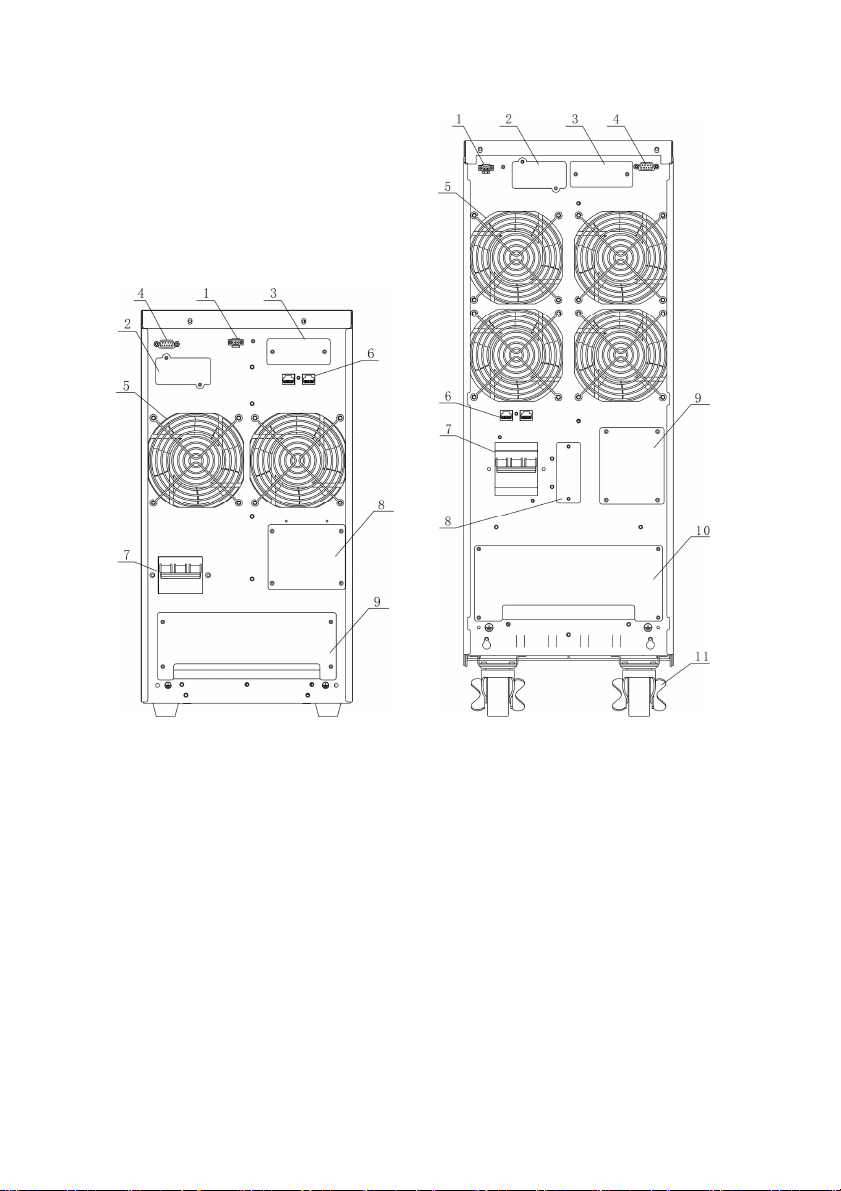
2.3 Appearance
33Q 10KL BACK VIEW 33Q 10K/33 20K(L)/33 30KL/33
40KL BACK VIEW
1. EPO Emergency shutdown switch 1. EPO Emergency shutdown switch
2. SNMP card 2. SNMP card
3. Parallel board install position 3. Parallel board install position
4. RS232 communication interface 4. RS232 communication interface
5. FAN 5. FAN
6. RJ45 6. RJ45
7. Input breaker 7. Input breaker
8. Wiring installation 8. Battery connect position
9. Terminal block 9. Wiring installation
10. Terminal block
11. Wheel
3. Installation
6
3.1 Unpacking and inspection
1. Check if the equipment is just what you wanted to purchase, you can affirm
through inspecting the model NO on back panel of the equipment.
2. Unpack the packaging and check the package contents. The shipping
package contains:
★ A UPS
★ A user manual and a CD
★ A communication cable
★ Long back up time UPS have one battery cable.
3. Inspect the appearance of the UPS to see if there is any damage during
transportation. Do not turn on the unit and notify the carrier and dealer
immediately if there is any damage or lacking of some parts.
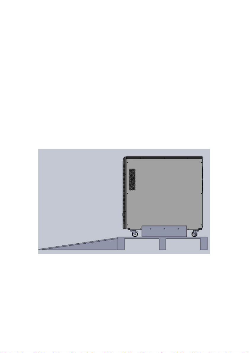
4. To unpacking the top of the plate structures in the whole machine packaging
wood base, the machine can be launched along the slope, the diagram below:
3.2 Installation notes
1. Consider the convenience of operation and maintain, the space in front and
back of the cabinet should be 100cm and 80cm respectively.
2. Keep good air circulation around UPS and far away from water, flammable
gas and corrosive.
3. The environment temperature around UPS should keep in a range of 0℃~
40℃. If the environment temperature exceed 40℃, the rated load capacity

7
should reduced by 12 percent per 5℃. The max temperature can’t be higher
than 50℃.
4. There will be phenomena of condensing if the equipment is dismantled or
installed under low temperature. The equipment can't be installed unless it is
full dry at internal and external of the equipment. Otherwise, there will be
danger of electric shock.
5. Battery group is advised used between 15℃~25℃. Don’t place UPS on
the slope and there should keep good air circulation between in-went on
front panel bottom and fan out-vent on rear panel.
6. Use a standard RS232 communication wire to connect the RS232 port and
the same port in computer, then install the software in the computer to
implement monitor of this UPS.
3.3 Installation
Installation and wiring must be performed in accordance with the local electric
code and the following instructions by professional personnel. For safety,
please cut off the mains power breaker before installation. The battery breaker
also needs to be cut off if it is a long backup time model.
1. Open the terminal block cover located on the rear panel of the UPS (please
refer to the appearance diagram).
2. The input and output wires connect to the UPS must accord with follow
sheet:
Model 33Q 10K(L) 33Q 20K(L) 33Q 30KL 33Q 40KL
Firing line 14AWG (2.5 mm2) 10AWG ( 4mm2) 8AWG (6mm2) 6AWG (16mm2)
Zero line 10AWG (4 mm2) 8AWG (6 mm2) 6AWG (16mm2) 4AWG (25mm2)
Ground line 10AWG (4 mm2) 8AWG (6 mm2) 6AWG (16mm2) 4AWG (25mm2)
Note:
Do not use the wall receptacle as the input power source for the UPS, as its
rated current is less than the UPS’s maximum input current. Otherwise the
receptacle may be burned and destroyed.
3. Connect the input and output wires to the corresponding input and output
terminals according to the following diagram.

8
Input and Output Terminal Block wiring diagram of 33Q 10KL
Input and Output Terminal Block wiring diagram of 33Q 10K/33 20K(L)/
33Q 30KL/33 40KL
Note:
You must make sure that the input and output wires and the input and output
terminals are connected tightly.
4. After having completed the installation, make sure the wiring is correct.
5. Please install the leak current protective breaker at the output power
distribution panel of the UPS if necessary.
6. To connect the load with the UPS, please turn off all the loads first, then
perform the connection and finally turn on the loads one by one.
7. No matter the UPS is connected to the utility power or not, the output of the
UPS may have electricity. The parts inside the unit may still have hazardous
voltage after turning off the UPS. To make the UPS have no output, power
off the UPS, and then disconnect the utility power supply.
8. Suggest charging the batteries for 8 hours before use. After connection, turn
the input breaker in the “ON” position, the UPS will charge the batteries
automatically. You can also use the UPS immediately without charging the
batteries first, but the backup time may be less than the standard value.

9
9. If it is necessary to connect the inductance load such as a monitor or a laser
Battery voltage
192
VDC
240
VDC
384
VDC
384
VDC
8AWG
6AWG
6AWG
4AWG
printer to the UPS, the start-up power should be used for calculating the
capacity of the UPS, as its start-up power consumption is too big when it is
started.
3.4 Operating procedure for connecting the long backup
time model UPS with the external battery
1. The nominal DC voltage of external battery pack is 192VDC for 33Q 10K,
and 240VDC for 33Q 20K, 384VDC for 33Q 30K/40K. Each battery pack
consists of 16 /20/32 pieces of 12V “maintenance-free” batteries in series.
To achieve longer backup time, it is possible to connect multi-battery packs,
but the principle of “same voltage, same type” should be strictly followed.
2. For 33Q 10-40K UPS, the procedure of installing battery bank should be
complied with strictly. Otherwise you may encounter the hazardous of
electric shock.
★ A DC breaker must be connected between the battery pack and the UPS.
The capacity of breaker must be not less than the data specified in the general
specification as follow.
Model 33Q 10KL 33Q 20KL 33Q 30KL 33Q 40KL
Battery current 55.5A 89A 83A 111A
★ Set the battery pack breaker in “OFF” position and connect the 16、20 or 32
pieces of batteries in series. And the battery wires must be follow the sheet
need:
Model 33Q 10K(L) 33Q 20K(L) 33Q 30KL 33Q 40KL
Battery wire
3. To complete the connection by plugging the connector of the external
battery cable into the external battery socket of the UPS. Do not attempt to
connect any loads to the UPS now. You should connect the input power wire
to the right position first. And then set the breaker of the battery pack in the
“ON” position. After that set the input breaker in the “ON” position. The
UPS begins to charge the battery packs at the time.
(6 mm2)
( 16mm2)
(16mm2)
(25mm2)

4. Parallel operation
Model No.
Capacity of breaker
33Q
10KL
≥32A/250VAC
33Q 20KL
≥50A/250VAC
33Q 30KL
≥60A/250VAC
33Q 40KL
≥80A/250VAC
4.1 Brief introduction of the redundancy
N+X is currently the most reliable power supply structure. N represents the
minimum UPS number that the total load needs; X represents the redundant
UPS number, i.e. the fault UPS number that the system can handle
simultaneously. The bigger the X is, the higher reliability of the power system
is. For occasions where reliability is highly required, N+X is the optimal mode.
As long as the UPS is equipped with parallel cables, up to 8 of them can be
connected in parallel to realize output power sharing and power redundancy.
4.2 Parallel installation
1. Users need to opt a standard 25-pin communication cable, which should
have 25 cores, corresponding stitches and shield, as the UPS parallel cable.
The length of the parallel cable is appropriate to be less than 3 m.
2. Strictly follow the stand-alone wiring requirement to perform the input
wiring of each UPS.
3. Connect the output wires of each UPS to an output breaker panel first, and
then connect the wiring to the load via the breaker panel.
4. The parallel UPS must be equipped with battery individually.
5. Please refer the figure followed to see the wiring of parallel operation. The
capacity of the breaker must be not less than the specification as follow.
*The requirement of the output wiring is as follows:
★ When the distance between the UPSs in parallel and the breaker panel is
less than 20 meters, the difference between the wires of input & output of the
UPSs is required to be less than 20%;
★ When the distance between the UPSs in parallel and the breaker panel is
greater than 20 meters, the difference between the wires of input & output of
the UPSs is required to be less than 10%.
10

4.3 Operation and maintenance
1. To perform the general operation, follow the stand-alone operating
requirement.
2. Start up: The units transfer to INV mode simultaneously as they start up
sequentially in utility power mode.
3. Shutdown: the units shut down sequentially in INV mode. When the last one
completes the shutdown action, each unit will shut down the inverter
simultaneously and transfer to bypass mode.
4. To perform the maintenance, follow the stand-alone requirement.
11

33Q 10KL Parallel Installation Wiring Diagram
12

33Q 10K/33 20K(L)/ 33 30KL/33 40KL Parallel Installation Wiring Diagram
13

5. Operation introduce
5.1 Operation Display Panel
1. ON button:
Pressing the ON button more than 1 second (buzzer beeps once), the UPS
system is turned on.
2. OFF button:
By pressing this button more than 1 second (buzzer beeps once) turns off the
UPS system whenever the UPS run under the normal mode/battery mode.
3. Function button
The Function button provides the following functions:
★ Battery self- diagnosis: When the UPS ran in normal mode, pressing this
button more than 5 seconds (buzzer beeps twice) can start the battery
self-diagnosis.
★ Silence function in battery/bypass mode
In battery/bypass mode, when the buzzer beeps, pressing and holding the
function button for more than 5 seconds (buzzer beeps two times) can silence
the buzzer. Press the button for more than 5 seconds (buzzer beeps twice) again
to resume the alarm function.
★ LCD display screen switch
Pressing the function button for more than 1 seconds (buzzer beeps once) to
switch LCD display screen.
4. LED indicators
The LED indicators contains Fault indicator, Bypass indicator, utility power
indicator, Inverter indicator, Battery indicator. The definition of each indicator
is the same as LED panel (refer to table Appendix 1).
14

5.2 Operation Mode
1. UPS operation mode contains normal mode, battery mode and bypass mode,
self test mode and fault mode.
2. Under the four modes, the page showing output voltage and output
frequency is the main display page. Under the fault mode, the page showing
fault code is the main display page.
3. If users need more information about UPS, Pressing the function button can
initiate display screen switch. If the current page is not the main page, UPS
will auto switch back the main page after 30 seconds.
4. In order to extend the LCD usage life, the backlight will turn off after 1
minute without any switch operation. At this point, Users just need to touch
any button briefly, the backlight will be turn on.
5.2.1 Normal mode
When operating in the normal mode, the display of main page on the front
panel is shown as the figure 5-2. The utility power indicator and the Inverter
indicator are turn on. Load information area shows load value, and the battery
level area indicates dynamically when the battery is not full charged (the
battery level icons lit one after another circularly). When the battery is full
charged, all the level icons are turn on.
1. If the utility power indicator blinks, it indicates that there are problems with
reversed polarity (L, N) of site wiring or disconnect with ground. UPS is still
working in normal mode. If the battery indicator is turn on at the same time,
it shows that the voltage or frequency of the utility power is out of the
normal input range of the UPS. The UPS works in battery mode.
Figure 5-2 Normal Mode
2. If load is more than 105 percent, the buzzer beeps twice every second,
meanwhile, the warning icon blinks every second too, reminding that you
15

have been overloaded. You should get rid of some unnecessary loads one by
one to decrease the loads until the alarm clear.
3. If the battery indicator blinks, it indicates that no battery is connected to the
UPS or battery voltage is too low. You should check if battery is properly
connected to the UPS, and press function button more than 5 seconds to start
the battery self-diagnosis. If the connection between battery and UPS is
confirmed without any problem, it may be due to the defect or aging of the
battery, please refer to the “troubleshooting” in chapter 8 to solve the
problem accordingly.
4. The other four display pages are load percent page, actual load page, input
information page and the maximum temperature page.
Note:
Connection to the power generator should be made according to the following
steps:
★ Activate the power generator and wait until the operation is stable before
connecting the output of the power generator to the UPS (be sure that the
UPS is in idle mode). Then, turn on the UPS according to the startup
procedure. After the UPS is turned on, the loads are connected one by one.
★ It recommended that the capacity of the AC generator chosen should double
that of the UPS.
5.2.2 Battery Mode
When operating in the normal mode, the display of main page on the front
panel is shown as the figure 5-3. The battery indicator and the Inverter
indicator are turn on. If the utility power indicator blinks at the same time, it
shows that the utility power is abnormal. Load information area shows load
value, and bat level area shows current battery capacity.
1. When the UPS is running in battery mode, the alarm will beep every 4
seconds. If the “Function” key is pressed for more than 5 seconds, the alarm
will not beep (silence function). Press the “Function” key more than 5 seconds
again to resume the alarm function.
16

Figure 5-3 Battery Mode
2. When the battery capacity decreases, the number of load/battery capacity
indicators turned on will decrease. If the battery voltage drops to the
pre-alarm level (capable of maintaining the backup time for more than 2
minutes), the alarm will beep every second to remind the user of insufficient
battery capacity.
3. The other four display pages are load percent page, actual load page, battery
information page and the maximum temperature page.
5.2.3 Bypass Mode
When operating in bypass mode set up through UPSilon software, the display
on the front panel is shown as the figure 5-4, the utility power indicator and the
bypass indicator are turn on. The load/battery capacity indicator will be turned
on in accordance with the load capacity connected. Load information area
shows load value, and the battery level area indicates dynamically when the
battery is not full charged (the battery level icons lit one after another
circularly). When the battery is full charged, all the level icons are turn on.
1. When operating in bypass mode, the UPS beeps every 2 minutes. If the
“Function” key is pressed for more than 5 seconds, the alarm will not beep
(silence function). Press the “Function” key more than 5 seconds again to
resume the alarm function.
2. If the utility power indicator blinks, it shows that the voltage or frequency of
the utility power is out of the input range of the UPS or there are problems
with reversed polarity (L/N) of site wiring or disconnect to the ground for
protection.
3. The other four display pages are load percent page, actual load page, input
information page and the maximum temperature page.
17

Notes:
When operating in bypass mode, the backup function of the UPS is not
available and the power used by the load is directly from the utility power via
internal EMI filter.
Figure 5-4 Bypass Mode
5.2.4 LCD indication of UPS alarm status and faults
In the event of an UPS fault, UPS enters fault operation mode, at this point, the
fault icon turn on consistently, the buzzer beeps continuously and the data
information area shows current fault code (refer to Appendix), the display on
the front panel is shown as the figure 5-5.
Figure 5-5 Fault display
When a warning occurred, the fault icon blinks every second, and users can
switch to the alarm display page shown as the figure 5-6 to check the warning
code.
18

Figure 5-6 Alarm display
5.3 Setting the output voltage and frequency
1. Connect the mains input to the UPS, and make the UPS works in standby
mode or bypass mode.
2. Press the ‘F’ and ‘OFF’ button more than one second, then release, the
buzzer will beep once, the “OUTPUT” is flashing, which means all of
bottom are used for UPS setting, at this point, if the “VAC” is flashing,
which means the output voltage is set to enable; if the “Hz” is flashing,
which means the frequency is set to enable, the LCD screen indicator
represents current output voltage and frequency setting value.
3. If you need to set the voltage, check the voltage setting is enabled (“VAC” is
flashing). If not, press the ‘F’ more than one second, then release,the output
setting is enabled, at this point you can start to set output voltage.
4. Release the ‘OFF’ key after you press it more than one second, LCD display
the selected output voltage in turn.
5. Repeat the fourth step until the LCD indicator meets the required voltage.
6. Press ‘ON’ key about one second, the output voltage setting completed.
7. The frequency setting is the same as the voltage setting, but before the
setting, please confirm the frequency setting is enabled, if not, press ‘F’ key
about one second in order to switch to the frequency setting screen (“Hz” is
flashing).
8. When done, Press the ‘F’ and ‘OFF’ button more than one second, then
release, the buzzer will beep once, exit the setting mode.
In the setting process, if no key is detected within twenty second, the UPS exits
the setting screen automatically.
19

6. Communication
This series is equipped with an intelligent slot for Web power (optional
accessory) or other optional card to achieve remote management of the UPS.
Please contact your local distributor for further information. Provide computer
RS232 serial communication interface, to monitor the input power supply and
UPS information, and control the state of UPS.
6.1 RS232 communication
The standard RS232 port is applicable to communicate with computer.
Description and pin assignment of RS232
Baud rate: 2400bps
Data bit: 8 bit
Ending bit: 1bit
Parity bit: None
DB-9 pin assignment:
RS232 Interface
Pin number Function description
3 Rxd Input
2 Txd Output
5 GND Ground
6.2 AS400 card communication
User enables to monitor and manage the UPS through installed the AS400 card
(optional).
PIN1: UPS failure (normally open, active close)
PIN2: Summary alarm
PIN3: Ground
PIN4: Remote shutdown
PIN5: Common
PIN6: Bypass active (relay close)
PIN7: Low battery
PIN8: UPS on (relay close)
PIN9: Utility Power failure (normally open, active close)
20
I/O

AS400 Interface
21

7. Battery
7.1 Battery maintenance
1. This series UPS only requires minimal maintenance. The battery used for
standard models is valve regulated sealed lead-acid maintenance free battery.
These models require minimal repairs. The only requirement is to charge the
UPS regularly in order to maximize the expected life of the battery. When
being connected to the utility power, whether the UPS is turned on or not,
the UPS keeps charging the batteries and also offers the protective function
of overcharging and over discharging.
2. The UPS should be charged once every 4 to 6 months if it has not been used
for a long time. In the regions of hot climates, the battery should be charged
and discharged every 2 months. The standard charging time should be at
least 12 hours.
3. Under normal conditions, the battery life lasts 3 to 5 years. In case if the
battery is found not in good condition, earlier replacement should be made.
Battery replace event should be performed by qualified personnel.
4. Replace batteries with the same number and same type of batteries.
5. Keep the ambient temperature between 15℃ and 25℃.
6. Do not replace the battery individually. All the batteries should be replaced
at the same time following the instructions of the battery supplier.
7. Normally, the batteries should be charged and discharged once every 4 to 6
months. Charging should begin after the UPS shuts down automatically in
the course of discharging, the standard charging time for the standard UPS
should be at least 12 hours. Discharge the battery with the load more than
50%.
7.2 Notes for battery disposal and replacement
1. Before disposing batteries, remove conductive articles such as necklace,
wrist watches and rings.
2. If it is necessary to replace any connection cables, please purchase the
original materials from the authorized distributors or service centers, so as to
avoid overheat or spark resulting in fire due to insufficient capacity.
3. Do not dispose of batteries or battery packs in a fire, they may explode.
4. Do not open or mutilate batteries, released electrolyte is highly poisonous
and harmful to the skin and eyes.
5. Do not short the positive and negative electrodes of the battery, otherwise, it
may result in electric shock or fire.
22

6. Make sure that there is no voltage before touching the batteries. The battery
circuit is not isolated from the input potential circuit. There may be
hazardous voltage between the battery terminals and the ground.
7. Even though the input breaker is disconnected, the components inside the
UPS are still connected with the batteries, and there are potential hazardous
voltages. Therefore, before any maintenance and repairs work is carried out,
switch off the breaker of the battery pack or disconnect the jumper wire of
connecting between the batteries.
8. Batteries contain hazardous voltage and current. Battery maintenance such
as the battery replacement must be carried out by qualified personnel who
are knowledgeable about batteries. No other persons should handle the
batteries.
23

8. Appendix
In the event of an UPS fault, shoot the trouble according to Table. If the fault
still persists, please contact our customer service center.
8.1 Fault code
Faults
Fault/
Warning
code
F01
F02
F03
F04
F05
F06
F07
F08
F09
F10
F11
F12
F13
F14
F15
Fault icon Alarm
On
constantly
On
constantly
On
constantly
On
constantly
On
constantly
On
constantly
On
constantly
On
constantly
On
constantly
On
constantly
On
constantly
On
constantly
On
constantly
On
constantly
On
constantly
Beep
continuously
Beep
continuously
Beep
continuously
Beep
continuously
Beep
continuously
Beep
continuously
Beep
continuously
Beep
continuously
Beep
continuously
Beep
continuously
Beep
continuously
Beep
continuously
Beep
continuously
Beep
continuously
Beep
continuously
Possible cause Solution
Bus soft start fails
BUS over voltage
fault
BUS low voltage
fault
Bus unbalance
BUS short
INV soft start fails
INV over voltage
fault
INV low voltage
fault
R/S INV short
R INV short
EPO fault
T INV short
S INV short
S/T INV short
R/T INV short
24
Please contact the distributor
or Service center.
Please contact the distributor
or Service center.
Please contact the distributor
or Service center.
Please contact the distributor
or Service center.
Please contact the distributor
or Service center.
Please contact the distributor
or Service center.
Please contact the distributor
or Service center.
Please contact the distributor
or Service center.
Turn off the UPS. Remove
all loads. Ensure that the
loads are not failed or the
UPS has no internal short
before turn on it again. If
failed, please contact the
distributor or service center.
Check the EPO switch be
take off or connect tighten.
Turn off the UPS. Remove
all loads. Ensure that the
loads are not failed or the
UPS has no internal short
before turn on it again. If
failed, please contact the
distributor or service center.

Fault/
Warning
code
F16
F17
F18
F19
F21
F22
F23
F24
F25
F27
F32
F34
F35
F55
F56
F57
Faults
Fault icon Alarm
On
constantly
On
constantly
On
constantly
On
constantly
On
constantly
On
constantly
On
constantly
On
constantly
On
constantly
On
constantly
On
constantly
On
constantly
On
constantly
On
constantly
On
constantly
On
constantly
Beep
continuously
Beep
continuously
Beep
continuously
Beep
continuously
Beep
continuously
Beep
continuously
Beep
continuously
Beep
continuously
Beep
continuously
Beep
continuously
Beep
continuously
Beep
continuously
Beep
continuously
Beep
continuously
Beep
continuously
Beep
continuously
Possible cause Solution
INV negpower
R inv negpower
S inv negpower
T inv negpower
Inv React Power
Overload Fault
Inv over
temperature
Inv relay open
Inv relay stick
Converter Over
Temperature
Communication
line loss
Can fault
Syn line fault
Ntc abnormal
Para line loss
Bat abnormal
Please contact the distributor
or Service center.
Please contact the distributor
or Service center.
Please contact the distributor
or Service center.
Please check parallel line
connect or not.
Please contact the distributor
or Service center.
Please contact the distributor
or Service center.
Please contact the distributor
or Service center.
Please contact the distributor
or Service center.
Please contact the distributor
or Service center.
Maybe the fan out of work
or the environment temp. is
to high.
Check the parallel line is
connect OK.
Please contact the distributor
or Service center.
Please contact the distributor
or Service center.
Please contact the distributor
or Service center.
Please contact the distributor
or Service center.
Check the battery number or
voltage is right.
25

8.2 Warring code
Phase sequence
Battery voltage
Faults
Fault/
Warning
code
A01
A03
A04
A08
Fault icon Alarm
Blink once
every second
Blink once
every second
Blink once
every second
Blink once
every second
4min beep one
sound
2min beep one
sound
4min beep one
sound
4min beep one
sound
Possible cause
Input Line
unbalance
Eeprom fault
Line fail Please check line voltage.
Bypass fail Please check line voltage.
Please check R/S/T line
voltage and frequency.
Please off the UPS and
shutdown by itself.
Solution
INV Bypass
is inconsistent
Battery
unconnected
low
Battery
overcharging
Overload
pre-warning
Overload fault
Fan failure
Charger fail
ID repetition
Please off the UPS and then
on the UPS in line mode.
Please check battery line
connect or not.
The UPS output will be cut
off, please switch to the
backup power.
Please contact the distributor
or Service center.
Reduce the member of loads
connected to the UPS.
Reduce the member of loads
connected to the UPS.
Ensure that the fan is not
locked
Please contact the distributor
or Service center.
Please check the battery
cables connect or not.
Please contact the distributor
or Service center.
A09
A10
A11
A12
A14
A15
A16
A19
A21
A22
Blink once
every second
Blink once
every second
Blink once
every second
Blink once
every second
Blink once
every second
Blink once
every second
Blink once
every second
Blink once
every second
Blink once
every second
Blink once
every second
UPS troubleshooting of LCD panel indicator
Beep continuously
Beep one sound
every 30 second
Beep one sound
every second
Beep continuously
Beep two sounds
every second
Beep continuously
Beep one sound
every second
Beep one sound
every second
Beep 8 sounds Start UPS fail
Blink once every
second
When you contact the service center, please provide the following information:
★ Model No. and the serial No. of the UPS;
★ The date when the problem arose;
26

★ Complete description of the problem, including the LED display, alarm
warning, power condition and load capacity. If your UPS is a long backup time
model, you may also provide the battery information.
8.3 Specifications and performance
Model 33Q 10KL 33Q 10K 33Q 20KL 33Q 20K 33Q 30KL 33Q 40KL
Rated power 10KVA/8KW 20KVA/16KW 30KVA/24KW 40KVA/32KW
Voltage range
Input
Output
Dimension(L*W*H)
Breaker 32A 50A 60A 80A
Frequency 40~60Hz (50Hz ) /50~70Hz (60Hz)
Factor > 0.99
Voltage 220V (1±1%)
Current 15A 30A 45A 61A
Factor 0.8
Line mode:
Frequency
Distortion THD < 3% (R full load)
Overload
capacity
Current crest
ratio
Efficiency Line: ≥ 93%, Bat: ≥ 90%
Rated bat No. 192VDC 240VDC 384VDC
Charge current 1A/7.5A 1A/6A 5.5A
ECO/EPO Optional
Short protect YES
Noise (dB) ≤ 60dB
mm
Weight (kg)
(1) synchronized 46~ 54Hz;
(2) 50Hz (line 40~ 46 or 54~ 60Hz);
Bat mode: 50Hz.
105% - 125% transfers to bypass mode after 1 minutes; 125% ± 5%< load ≤
150% ± 5% transfers to bypass mode after 30second
533*260*501
26 95 57.5 107 59.5 62.5
Note:
Output voltage can be set: 200V/208V/220V/230V/240V.
Frequency can be set as 60Hz.
Operating environment:
Temperature Humidity Altitude Storage temperature
0℃-40℃ <95% <1000m 0℃-40℃
(274-478) VAC (Full load)
3:1
710*260*717
27

Note:
If the UPS is installed or used in a place where the altitude is above than 1000m,
the output power must be decrease in use, please refer to the table:
Altitude(M) 1000 1500 2000 2500 3000 3500 4000 4500 5000
Load 100% 95% 91% 86% 82% 78% 74% 70% 67%
28
 Loading...