

Page 1
Page 2

No part of this document may be reproduced in any form
or by any means without the express written consent of
UPS Aviation Technologies, Inc.
UPS Aviation Technologies, Inc., II Morrow, and Apollo
are trademarks of UPS Aviation Technologies, Inc.
© 2000 by UPS Aviation Technologies, Inc.
All rights reserved. Printed in the U.S.A.
UPS Aviation Technologies, Inc.
2345 Turner Road S.E.
Salem, OR 97302
U.S.A. Toll Free 800.525.6726
Canada Toll Free 800.654.3415
International 503.391.3411
FAX 503.364.2138
Visit our web page at http://www.upsat.com
Send comments about this manual by e-mail to:
[email protected]
Page 3

History of Revisions
Date Software Version Manual Revision
January 2000 1.0 Capstone Release
February 2000 1.1 GA Release
April 2000 1.2 560-1026-00a
August 2000 2.0 560-1026-01
Ordering Information
To receive additional copies of the Apollo MX20 User’s
Guide, order part #560-1026-01. The Apollo MX20
Installation Guide is part #560-1025-xx. The MX20
Quick Reference Guide is part #561-0263-xx.
About This Manual
Please take a few moments to review the various sections
in this manual. Even if you are an experienced user of
Multi-Function Displays, be sure to read our Getting
Started section. This section provides the rules for
successful use of the Apollo MX20. The rest of the
manual contains important information that you can refer
to as you need more detail on specific procedures or
features. The MX20 advances the technology of
Multi-Function Displays and uses new state-of-the-art
features you will want to know about.
i
Page 4

End User License Agreement (“EULA”)
Refund. If you do not agree to the terms of this EULA, UPS Aviation Technologies and Microsoft
are unwilling to license the MX20 and its Operating System to you. In such event, you may not
use or copy the Licensed Product, and you should promptly contact UPS Aviation Technologies
for instructions on return of the unused product(s) for a refund.
Client Access Licenses. If you use the MX20 Operating System to access or utilize the services or
functionality of Microsoft Windows NT Server (all editions) or use the MX20 Operating System
to permit workstation or computing devices to access or utilize the services or functionality of
Microsoft Windows NT Server, you may be required to obtain a Client Access License for the
MX20 Operating System and/or each such workstation or computing device.
No Warranties. Except as expressly provided in the limited warranty section, the MX20 and its
operating system are provided to you “as is” without warranty of any kind, either expressed or
implied, including, but not limited to, warranties of noninfringement, merchantability, and/or
fitness for a particular purpose. the entire risk of the quality and performance of the software is
with the user.
No Liability for Consequential Damages. UPS Aviation Technologies and/or UPS Aviation
Technologies’ software suppliers shall not be held liable for any damages suffered or incurred by
you (including, but not limited to, general, special, consequential or incidental damages
including damages for loss of business profits, business interruption, loss of business information
and the like), arising from or in connection with the delivery, use, or performance of the software.
Customer Remedies. UPS Aviation Technologies’ and UPS Aviation Technologies suppliers’
entire liability and your exclusive remedy shall be, at UPS Aviation Technologies’ option, either
(a) return of the price paid, or (b) repair or replacement of the MX20 and its operating system
that does not meet the above Limited Warranty and which is returned to UPS Aviation
Technologies with a copy of your receipt. This Limited Warranty is void if failure of the MX20 or
its operating system has resulted from accident, abuse, or misapplication. Any replacement MX20
and its operating system will be warranted for the remainder of the original warranty period or
thirty (30) days, whichever is longer.
Limitations on Reverse Engineering, Decompilation and Disassembly. You may not reverse
engineer, decompile, or disassemble the MX20 or its operating system, except and only to the
extent that such activity is expressly permitted by applicable law notwithstanding this limitation.
Separation of Components. The MX20 and its operating system are licensed as a single product.
Its component parts may not be separated for use on more than one MX20.
Single Embedded System. The MX20 and its operating system are licensed with the MX20 as a
single integrated product. The MX20 operating system may only be used with the MX20 as set
forth in these licensing terms.
ii
Page 5

Welcome…
Welcome to a new era of aviation navigation. Once again,
UPS Aviation Technologies, Inc. has set new standards in
features and ease of use for the general aviation public.
The Apollo MX20 Multi-Function Display provides a
focal point for integrating many of your navigation needs
in an easy to use and convenient package.
The MX20 presents a wealth of information on its
six-inch diagonal, 640x480 pixel, color display. The many
features are organized as distinct functions and are
designed to closely mimic the traditional instruments used
in the standard cockpit. Each function allows varying
degrees of customization. The custom map function is
customizable so you can create a display for almost any
configuration you require. The other functions provide
more limited levels of customization so that they retain
the look and feel of the instruments they reflect.
The MX20 is capable of creating powerful overlay views
where information from a variety of sources can be
presented simultaneously in proper relationship to each
other, thus greatly increasing situational awareness for the
pilot.
You can be confident in knowing that you are the owner
of the state-of-the-art in aviation and navigation. The
MX20 architecture is designed to support full expansion
for both software and hardware enhancements. This
flexibility protects your investment and allows for the ease
of adding new features. Our products are built to last and
to allow the flexibility to meet your needs as they change
in the future.
iii
Page 6

About This Manual
This manual may be used as a summary, a reference, and
a learning tool. Information is provided about all of the
functions available to the MX20. Your specific installation
may not include all of these functions.
Take a few moments to familiarize yourself with the
various sections in this manual. The Getting Started
section gives an introduction to the controls, basic
operation, and organization of the functions in your
MX20. Be sure to read the Getting Started section to learn
the rules for using the MX20. The Detailed Operation
section is the reference for each of the functions in the
MX20. Refer to the Detailed Operation section when you
want to get into the details on every function and option
along with step-by-step instructions.
Not every function is available in all software versions or
installations. Check your Approved Flight Manual
Supplement to verify the features that are available.
iv
Page 7

Table of Contents
History of Revisions .......................i
Ordering Information ......................i
About This Manual .......................i
Welcome… ...........................iii
About This Manual .......................iv
Getting Started ............................1
Functions.............................1
Controls .............................3
Power/Brightness ......................3
Function ( FN) .......................3
Menu/Enter .........................4
Line Selection ........................4
Data Card ............................5
Display ..............................6
Annunciations ..........................7
Advisory Flags........................7
Traffic ..........................7
Terrain .........................7
Lightning ........................7
Data Flags ..........................8
Message Flag ........................8
Basic Operation .........................9
Power On ..........................9
Pre-Heat Mode .......................9
Brightness .........................10
Start Up Screen ......................10
Confirm Current Baro Correction ............11
Function Selection.....................11
Advisory hot key ......................12
Normal Cruise Condition ..............12
Viewing the Advisory .................12
Returning to Normal Condition ...........13
Options Menu .......................13
Summary ..........................14
v
Page 8

Detailed Operation .........................15
Message Log (MSG) Function ................16
Custom Map (MAP) Function ................17
Map Scale .........................17
Auto Zoom .........................18
Pan.............................18
Info .............................19
Info In Pan Mode .....................20
Flight Plan .........................21
Map Orientation ......................21
Invert ............................22
Nav Data ..........................22
Terrain ...........................23
Airports ...........................24
VORs ............................24
VOR Highlight ....................25
VOROBS.......................26
ILS/Localizer Depiction ...............26
Back Course Display .................27
NDBs............................27
Intersections ........................27
Airspace ..........................28
Low Airways ........................28
High Airways .......................29
Water ............................29
Roads ............................29
Boundary ..........................29
Obstructions ........................30
Traffic ...........................30
Strikes ...........................31
IFR Chart Function ......................32
Flight Plan .........................32
Map Orientation ......................32
Invert ............................33
vi
Page 9

Nav Data ..........................33
Label ............................34
Low Airways ........................34
High Airways .......................34
VFR Chart Function ......................35
Flight Plan .........................35
Map Orientation ......................35
Invert ............................36
Nav Data ..........................36
Label ............................36
Traffic Function ........................37
Traffic Description ....................37
TIS-B Traffic .....................38
Target Color......................38
Surface Targets ....................38
Flight Plan .........................40
Traffic Map Orientation .................40
Traffic Altitude Values ..................41
Display Mode .......................41
Graphic ........................41
Text ..........................41
Altitude Option (Relative/Pressure) ...........42
Time ............................42
ADS-B Broadcast Mode Control .............43
Broadcast FID.....................43
Broadcast VFR ....................43
Standby ........................44
Flight ID Editing .....................44
Traffic Altitude Filter ...................44
Flight Plan (FPL) Function ..................45
Terrain (TER) Function....................46
Flight Plan .........................48
TRK Up Arc/TRK Up 360 ................49
Set Barometer .......................49
TER Data Flag.......................49
Weather (WX) Data Link ...................50
Flight Information Service-Broadcast (FIS-B)........52
vii
Page 10

Navigating the Displayed Data..............53
Smart Key Function ....................53
Sorting FIS Messages ...................54
Lightning Strikes (LT) Function ...............55
Flight Plan .........................56
360/120 ...........................56
Lightning..........................56
Strike..........................56
Cell...........................56
Heading Stabilization ...................56
System Data ........................56
Demo ............................57
Self-Test ..........................57
Noise Monitor .......................57
Strike Test .........................58
System Function ........................59
System Nav Page .....................59
Ownship Symbol ...................59
Lat/Lon Format....................59
Set Baro Units.....................59
Set Baro Correction..................60
Display Lat/Lon Lines ................60
System Info.........................61
GPS and datalink status ...............61
System Test Page .....................62
Test Pattern 1 .....................63
Red, Green, Blue, White Test Pattern........63
Caring For Your MX20 ....................64
Display Care and Cleaning ................64
Troubleshooting ........................65
viii
Page 11

Getting Started
This section explains how to get started using the MX20.
Information in this section describes the controls, data
card, display, and basic operation. After reading this
section, go to the Detailed Operation section for expanded
explanations for each feature.
Functions
The MX20 contains eleven major separate functions for
the display of information. The function names are shown
as “smart” keys at the bottom of the display. The “smart”
key is the combination of a label above a triangle key at
the bottom of the display. The labels above the triangle
keys change to reflect the choices available to you for each
function. Press the
Press the “smart” key below the function label to go to the
displayed function. While in each function, press the
MENU/ENTER key to show the options for each function.
The options are shown on the right side of the display.
Press the
Some options toggle on/off, while some are tri-state (three
choices). The functions are:
LINE SELECT key to manipulate the options.
MSG - Message Log (See page 16 for details)
MAP - Custom Map (See page 17 for details)
IFR - IFR Chart (See page 32 for details)
VFR - VFR Chart (See page 35 for details)
TRAF - Traffic (ADS-B installations only)
(See page 37 for details)
FPL - Flight Plan (See page 45 for details)
TER - Terrain (See page 46 for details)
WX - Weather Data Link (See page 50 for details)
FIS-B - Flight Information Service - Broadcast (See
page 52 for details)
LT - Lightning Strikes (See page 55 for details)
SYS - System Information (See page 59 for details)
FN key to show the available functions.
Getting Started
1
Page 12

Getting Started
The Message Log displays information from the MX20 or
reported to the MX20 by its external sensors. A flashing
MSG annunciator notifies you of a new message that
should be viewed. The Custom Map function allows you
to completely customize the displayed map by overlaying
selected information. The Custom Map can become
“cluttered” if you choose every option, so use discretion.
The IFR Chart function provides an IFR enroute style
map on the display. The VFR Chart function provides a
VFR sectional style map for the display. The Traffic
function (when installed) shows nearby traffic and details
about each target. The Flight Plan function provides
details about your flight plan and each waypoint. The
Terrain function shows a color coded map of terrain
elevation in relation to your altitude. The Weather Data
Link function is capable of displaying graphic weather
information with UAT-equipped installations. The Flight
Information Services function allows access to text
weather data messages on UAT-equipped installations.
The Lightning function, when connected to the BF
Goodrich WX500 Stormscope, controls the overlay of
lightning strike information on the map displays. The
System Information function lets you set general
preferences, show software version information, and test
the display.
2
Page 13
Controls
F
F
OFF
Getting Started
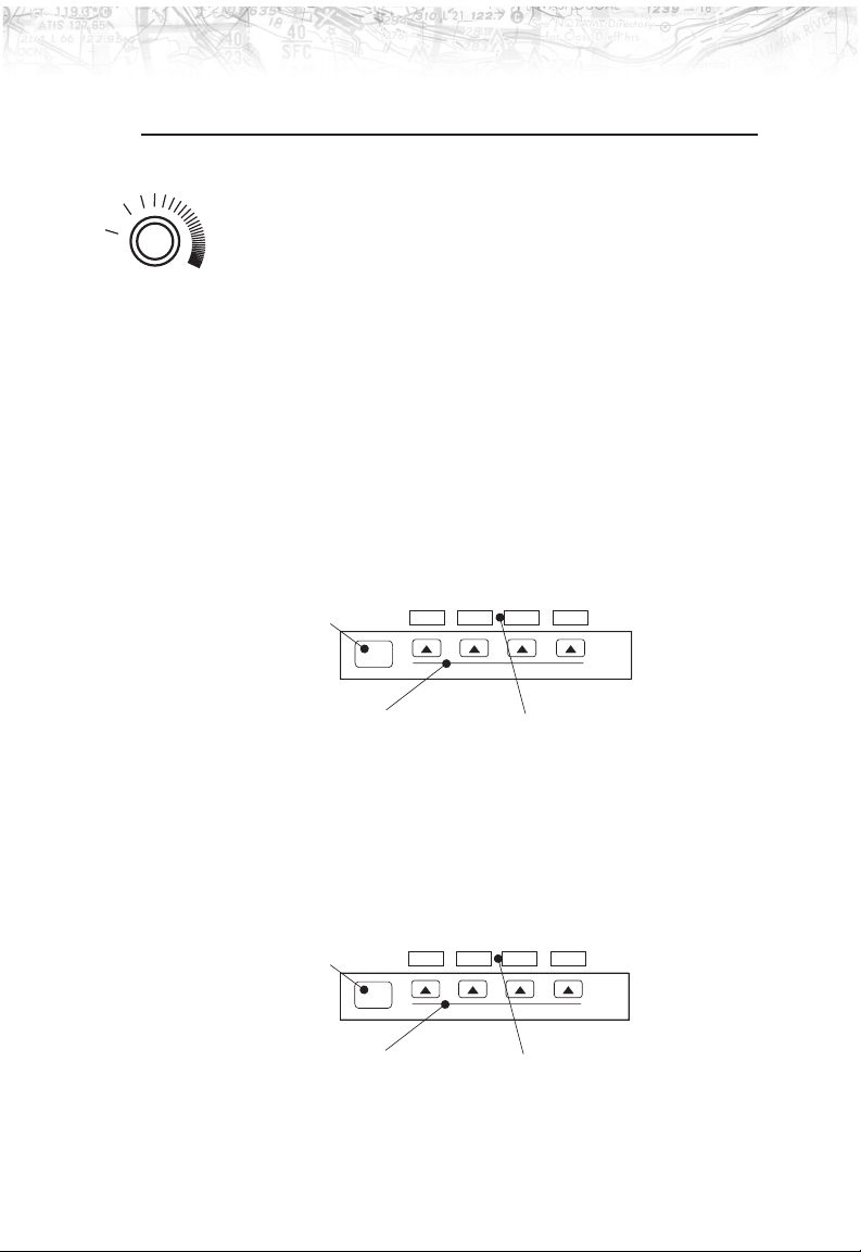
Power/Brightness
The power switch is located in the upper right corner of
the MX20. Turn the power rotary knob clockwise past the
detent to turn the power on. Turn the power knob fully
counterclockwise to turn the power off. With the power
knob pushed in, the brightness is set automatically
according to ambient light by a photosensor. Pull the
knob out and turn the knob to adjust the display
brightness manually.
Function ( FN)
The Function keys are made up of one dedicated key on
the lower left side of the display and the four “smart” keys
to the right of it. Press the function (
scroll through the available functions. The functions will
appear above the “smart” function keys in turquoise.
FN) key repeatedly to
unction Key
Smart Function Keys
Use the
FN key to display a list of the main functions, such
as Map, IFR, Terrain, etc. Each time you press the
MSG MAP IFR VFR
FN
Smart KeyLabels
FN key
you will step through the list of functions. After you press
one of the function “smart” keys at the bottom of the
display, the function keys change to provide options to
control the display related to the current function.
unction Key
Smart Function Option Keys
Change the function keys back to the function list by
pressing the
FN key.
In Out Pan Info
FN
Smart Key Labels
3
Page 14
Getting Started
Menu/Enter
MENU
ENTER
Line Selection
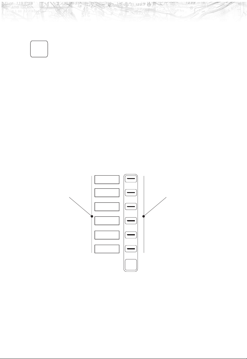
The MENU/ENTER key is located on the bottom right
corner of the MX20. Press the
MENU/ENTER key to show
a menu of options to modify the display of the current
function. Press the
MENU/ENTER key to hide the menu. If
no action is taken, the menu will automatically extinguish
in a few seconds.
The Line Selection keys are on the right side of the MX20.
Press the
current function. Press the
MENU/ENTER key to see the options for the
LINE SELECT key next to each
option to scroll through the choices for each option. Some
options support tri-state choices, such as in Map mode.
When you select a tri-state option, the option label will
change with each key press between completely filled,
partially filled, and empty.
Option 1
Option Labels
4
Option 2
Option 3
Option 4
Option 5
Option 6
MENU
ENTER
Line Select Keys
Page 15
Data Card
d
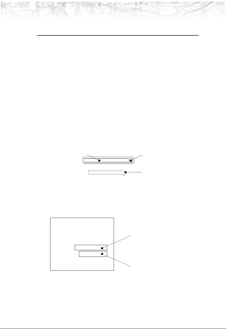
The Map database and other information is stored on a
data card. The use of a data card allows you to easily
update information.
Only change the data card when the power is turned
off.
Handle your data card carefully. Do not touch the
connector edge of the data card. To eject the card, use a
soft blunt object to press the data card ejector. Gently pull
the card straight out of the slot. Insert a data card by
pushing the card straight into the slot. When fully
inserted, the data card and eject button will be flush and
slightly recessed into the bezel.
Getting Started
Front View of Data Card Slot
Data Card EjectorData Card
Side ViewofDataCar
Front
When contacting your dealer or the UPS Aviation
Technologies technical services staff, eject the data card
and write down the information shown on the label.
UPS Aviation Technologies
APOLLO Mx20
P/N 138-0448-010
TSO C113, TSO C110A
DO-178B LEVELS C,D
DATE
S/W VERSION
Nav Data: Copyright Jeppesen Sanderson, Inc.
2000 UPS Aviation Technologies Inc.
All Rights Reserved.
Date of Jeppesen Nav data
Version of Mx20 software
5
Page 16
Getting Started
r
Display
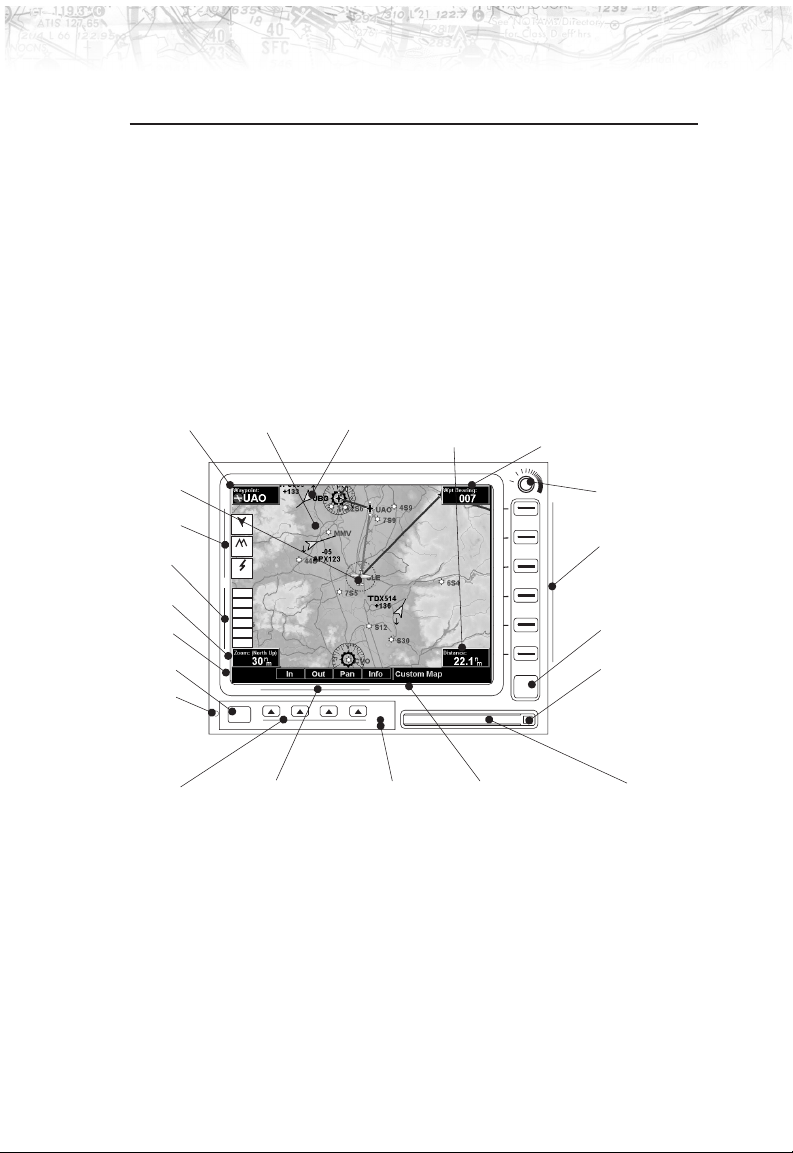
The MX20 display provides text and graphic information
to give a “picture” of your flight and surroundings. The
display brightness may be set manually or allowed to
automatically adjust to ambient light conditions. At the
bottom of the display, labels above the function keys
change to show the different choices for each function to
allow access to commonly used actions. A typical Custom
Map function display is shown below. See page 64 for
details on display care.
TO Waypoint Identifier
Ownship
Advisory Flags
Data Flags
Zoom
(Map Scale)
Message Flag
Function Key
Photosensor
Graphic Display
MFD
TRAF
TERR
STRK
POS
RTE
ALT
TRAF
LT
TER
FN
Smart Function Key Labels Currently Selected FunctionMounting Screw
ADS-B Traffic
Distance to
Destination Wpt
POLLOAMX20
Bearing to
Destination (TO) Wpt
OFF
MENU
ENTER
Power/Dimming
Line Select Keys
Menu/Enter Key
Data Card Ejecto
Data CardSmart Keys
The MX20 will go into a pre-heat mode for a short period
of time on start-up. During the pre-heat mode, the display
will remain dark. The pre-heat mode is designed to
extend the life of the LCD backlight.
6
Page 17
Annunciations
Advisory flags, data flags, and messages appear on the
display to give information about the status of the MX20
or to provide operating information.
Advisory Flags
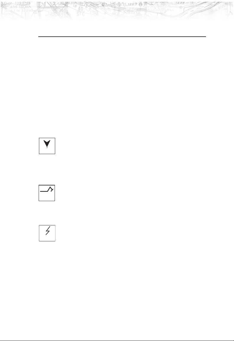
Annunciations will appear on the upper left side of the
display to provide advisories for Traffic, Terrain, and
Lightning. Advisory information is monitored and
displayed regardless of the selected function. Advisory
flags will flash for approximately 10 seconds when they
first appear and then turn solid while they are still valid.
Traffic
The Traffic advisory flag will appear on the left side of the
TRAF
TER
STRK
display when traffic is reported to be within ±2000 feet of
your altitude and 5 nm of your location. The Traffic
advisory and Traffic functions are only available when the
ADS-B system is installed.
Terrain
The Terrain advisory flag will appear on the left side of
the display when the terrain surface or obstacle altitude is
within approximately 500 feet of your altitude and within
approximately two minutes of flight in any direction.
Lightning
The Lightning advisory flag will show on the left side of
the display when the WX500 sends an indication that
lightning has been detected within 50 nm of your location.
See the WX500 manual for details about range and other
capabilities.
Getting Started
7
Page 18

Getting Started
Data Flags
Data flags appear on the left side of the display to notify
you when there is a loss of reported information. The data
usually displayed, such as lightning or nearby terrain, may
still exist, but may not be displayed for technical reasons.
For instance, when the amber TRAF data flag appears it
means that the MX20 is not receiving Traffic information.
Traffic may be present, but will not be displayed.
POS No valid position information is available from
the source. Do not expect a valid position
representation on the maps. The Ownship
symbol will have an “X” through it.
RTE No valid route (flight plan) is available from the
external navigation source. Route (flight plan)
information will not be shown on the maps.
ALT No valid altitude information is available from
the external source. Altitude related functions
will not operate, such as terrain awareness.
TRAF No traffic information is received from the
external source. Traffic will not be displayed.
Your position information will not be broadcast
in ADS-B capable systems.
LT No valid lightning detection information is
being received from the external source.
Strike and cell information will not be
displayed.
TER Terrain coverage is not available for some part
of the terrain advisory coverage area. Terrain
advisories may not be provided.
NAV When connected to the SL30, indicates the
SL30 is not available or valid. ILS, OBS, and
VORs will not be highlighted.
Message Flag
The Message flag will appear on the lower left side of the
display when a new message is posted. Go to the Message
function to view the information about the operation or
status of the MX20.
8
Page 19

Basic Operation
Use the following items to get a basic feel for the operation
of the MX20. The basic steps for using any of the separate
functions of the MX20 are:
Turn the power on.
Adjust the brightness or set it to automatic.
Check that all tests pass on the Start Up screen.
Press the
press of the
functions.
Press the key below the function label to select the
desired function.
Confirm or enter the current barometric pressure
Press the
options.
Press the
option to choose desired capabilities. Some options
use multiple key presses for different states for the
option. Press the
extinguish the option display.
Refer to the Detailed Operation section for more
details on each function.
FN key to view available functions. Each
FN key will step through the lists of
MENU/ENTER key to display available
LINE SELECT key next to the displayed
Getting Started
MENU/ENTER key again to
Power On
Turn the power rotary knob clockwise past the detent to
turn the power on. The MX20 will progress through a
series of startup screens. The final startup screen shows
System Information and the results of the Self-Test.
Pre-Heat Mode
The MX20 will go into a pre-heat mode for a short period
of time on start-up. During the pre-heat mode, the display
will remain dark. The pre-heat mode is designed to
extend the life of the LCD backlight.
9
Page 20

Getting Started
Brightness
Start Up Screen
With the Power knob pulled out, turn the knob in each
direction to adjust the display brightness manually.
Manual brightness mode may be selected to adjust the
display for difficult lighting conditions. Push the knob in,
and the brightness is adjusted automatically according to
the ambient light. When the brightness is set
automatically, the display will not dim below a
pre-defined level.
The Start Up screen is displayed while the MX20 goes
through its initialization and testing routines. System
information is shown that provides the MX20 software
and database versions. The results of the self test are
shown. A check mark shows that the test passed. If any of
the Self-Tests fail (red “x”), contact your dealer or the
factory (see page 64).
10
Page 21
Getting Started
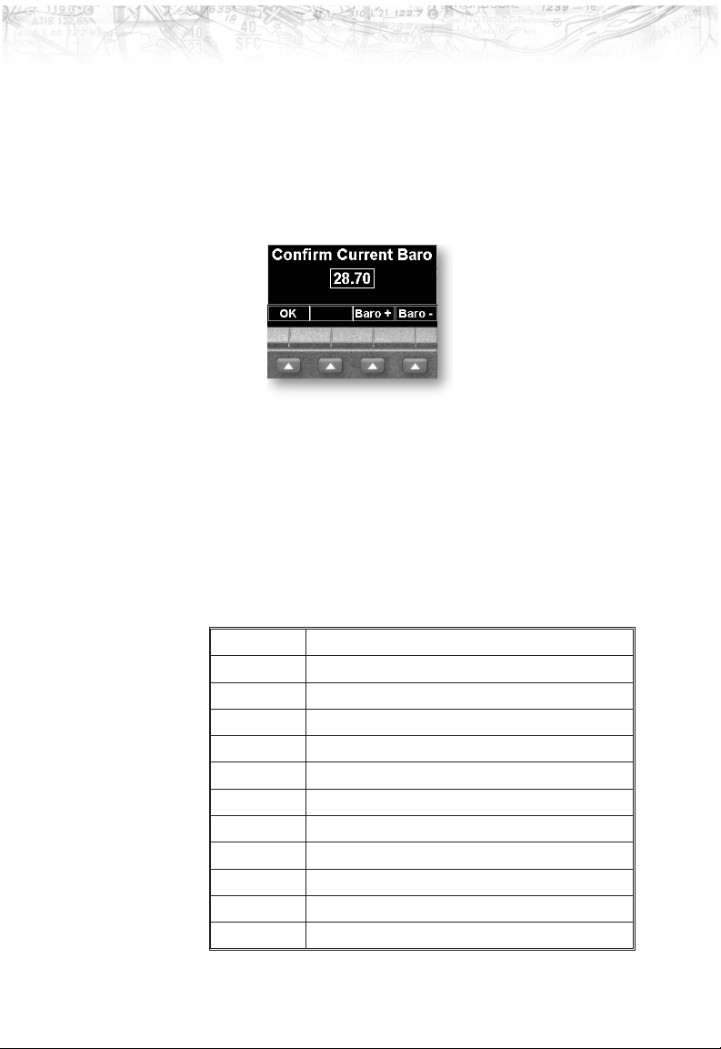
Confirm Current Baro Correction
A window that displays the current barometric value and
asks you to verify the current value or enter a new value.
This window will appear at startup and then every 30
minutes. Press
to decrease the value. Press OK to confirm the existing
-
BARO + to increase the value. Press BARO
values or to accept changes you have just entered.
Function Selection
Press the FN key to view the different Functions. The
functions are shown above the function “smart” keys on
the lower part of the display in green. Press the function
key under the function label to activate that function. The
labels above the function key will change to reflect the
custom “smart” controls for that function. All described
functions may not be available in each installation.
Function Description
MSG Message Log Function
MAP Custom Map Function
IFR IFR En Route Map
VFR VFR Sectional Map
TRAF ADS-B Traffic reporting
FPL Flight Plan information
TER Terrain Depiction
LT Lightning detection and reporting
WX Graphical Weather
FIS Text Weather
SYS System Information
11
Page 22

Getting Started
Advisory Hot Key
The ‘Advisory Hot Key’ feature allows advisory
conditions to be quickly viewed with minimal effort by the
pilot. This feature is comprised of three components:
1) An advisory condition is indicated by a white advisory
flag on the left side of the screen, the corresponding
Function label will also be highlighted in white when
selecting a new Function via the FN key. This feature
allows any Function with a pending advisory to quickly
be recognized in the Function menu.
2) When a function is entered that has an advisory posted,
the zoom level will be adjusted to show the advisory
causing object (terrain for example), and the map mode
will be forced to ‘360 ARC mode’ to get a good view of
what is around the aircraft.
3) When returning to the previous Function after viewing
a Function with an advisory, the original zoom and
map mode will be restored.
This feature is designed to allow the pilot to establish a
preferred ‘cruise’ map setup and quickly view an advisory,
then return back to the previous setting. For example:
Normal Cruise Condition
Custom Map Function is being viewed at 5NM in the
ARC mode.
Terrain Advisory Occurs at 10nm in front of aircraft: The
Terrain Advisory Indicator flashes then goes steady on the
left side of the display.
Viewing the Advisory
The pilot presses the FN key and sees the TER Function
highlighted in white, indicating it has an advisory
condition. Pressing the TER key to enter the Terrain
Function at this point will automatically adjust the zoom
level to 10nm and place the unit in full ‘360’ mode to
show overall situational awareness.
12
Page 23

Getting Started
Returning to Normal Condition
After evaluating the advisory, to return to normal viewing
simply select the original Function that was being viewed
before the advisory was viewed. When this is done, the
zoom level will be set back to 5 nm and the display mode
will be returned to ARC mode.
Options Menu
Most functions have a number of options available. Press
the
MENU/ENTER key to see the options for the current
function. You change an option by pressing one of the
Line Selection keys that are to the right of the displayed
option. Many options have more than one choice. Press
the same
available choices. Some functions have several pages of
options. The lower
reach the Next Page when multiple pages are available.
Press the
menu from view or wait a few seconds for the options to
automatically extinguish.
LINE SELECT key repeatedly to select the
LINE SELECT key will allow you to
MENU/ENTER key a second time to remove the
13
Page 24
Getting Started
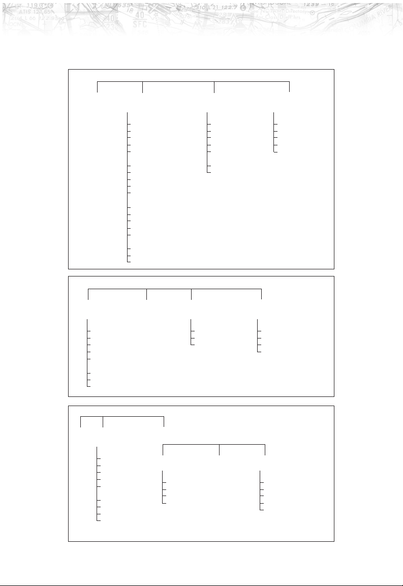
Summary
Press Function Keys
MSG MAP IFR VFR
Flight Plan
Map Orient
Invert
Nav Data
Terrain
Airports
VORs
Press Line Selection Keys
NDBs
Intersections
Airspace
Low Airways
High Airways
Water
Roads
Boundary
Obstructions
Traff ic
Strikes
Press Function Keys
Flight Plan
Map Orient
Invert
Nav Data
Label
Low Airways
High Airways
Press Line Selection Keys
TRAF FPL TER WX
Flight Plan
Map Orient
Display Mode
Altitude
Time
Broadcast FID
Enter FID
Press Line Selection Keys
Altitude Filter
Press Function Keys
Flight Plan
Map Orient
Set Barometer
Press Line Selection Keys
Press Line Selection Keys
Flight Plan
Map Orient
Invert
Nav Data
Label
Press Line Selection Keys
Flight Plan
Map Orient
Invert
Clear
FIS LT SYS
Flight Plan
360/120
Lightning
Hdg Stab
System Data
Demo
Self Test
Press Line Selection Keys
Noise Monitor
Strike Test
14
Press Function Keys
Nav
Ownship Symbol
Lat/Lon Format
Set Baro Correction
Display Lat/Lon Lines
Press Line Selection Keys
Info Test
Press Line Selection Keys
Test Pattern 1
Red Test Pattern
Green Test Pattern
Blue Test Pattern
White Test Pattern
Page 25

Detailed Operation
This section describes each operating function and the
options available in each function. Each function operates
independently. The Function “smart” keys and Line
Selection keys are customized for each function and will
appear while that function is selected. The functions are
described in the order that they appear. A description of
each function will be followed by an explanation of how
the function “smart” keys operate for the function and
then each menu option as selected by the Line Selection
keys. All described functions may not be available in your
pariticular installation. See your Airplane Flight Manual
supplement for the details on your individual installation.
Detailed Operation
15
Page 26
Detailed Operation
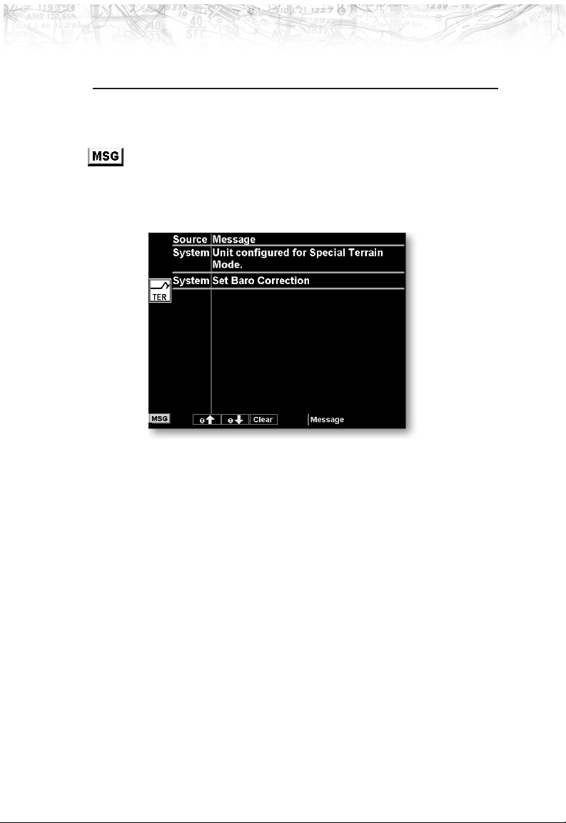
Message Log (MSG) Function
The Message function displays information about the
status of the MX20. Messages may be logged by either the
MX20 internal system or by one of the external sensors.
The amber MSG flag will flash until the message is
viewed. The MSG flag will remain in view while any
messages remain in the message log. New messages that
have not been viewed will be highlighted as bold text.
1. Press
2. Press the
3. Use the
FN until you see the MSG function key.
MSG key.
UP/DOWN arrow “smart” keys to move to
additional messages, if more than one page of messages
exist.
4. Press
16
CLEAR to remove the stored messages.
Page 27

Custom Map (MAP) Function
The Custom Map function provides a graphic display of
map features in relation to the aircraft location to help
improve your situational awareness. The custom map
function is unique in that it has the ability to selectively
“overlay” all available types of information onto a single
display. You can customize the map display by overlaying
information selected from a menu of options. Press the
MENU key to display a list of options on the right side of
the screen. Press the
displayed option. Repeated presses of the
key will scroll through the available selections for each
option.
The “smart” keys at the bottom of the display over the
function keys control the map scale by zooming in or out,
moving the map view around with the Pan feature, and
viewing Info about the current destination waypoint.
Map Scale
The In and Out function keys control the map scale by
zooming in and out. You can zoom in to 0.25 nm and
zoom out to 250 nm. The scale distance is measured from
the location of your aircraft symbol to the top of the
screen. The Map Scale is shown in the lower left corner of
the screen. The map orientation appears above the map
scale on one of the three Nav Data options.
LINE SELECT key next to the
Detailed Operation
LINE SELECT
Zoom Level
Map Orientation
17
Page 28
Detailed Operation
Auto Zoom
Pan
Auto Zoom is activated by adjusting the zoom level to the
far extremes of the zoom range. When activated, the
indicated zoom level will change from a number to the
text ‘AUTO’.
While in the Auto Zoom mode, the screen will
automatically adjust the current zoom level to maintain
the current ‘TO’ waypoint on the screen. When
approaching the waypoint, the zoom level will not drop
below 1 nm. When the waypoint is reached and the next
waypoint in the flight plan becomes active, the zoom level
will automatically adjust to bring that waypoint on the
map.
To exit the autozoom mode, simply increase or decrease
the current zoom level to re-enter the manual adjust
mode.
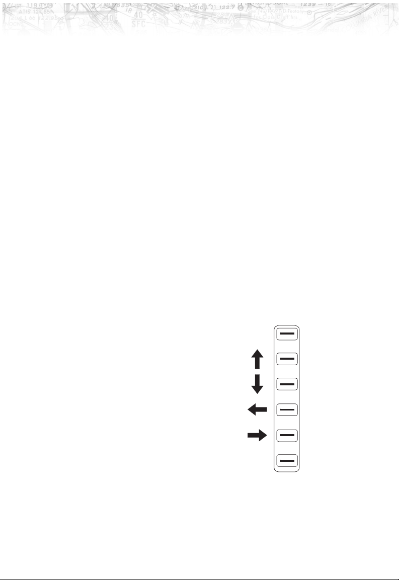
The Pan keys are used to move the display around so you
can see beyond the
initial boundaries of
the screen. The
PAN
function key is one of
the “smart” keys
available at the
bottom of the screen.
When you select the
Pan function, four
“arrow” keys appear
on the right side of
the screen next to the
LINE SELECT keys.
Move the map in the
desired direction by pressing the
LINE SELECT key next to
the arrow that shows you want the map to move. Press the
PAN key again to exit the Pan mode. While panning, a
18
Page 29
Detailed Operation
green reference line is drawn from the center of the
viewed area back to your current position.
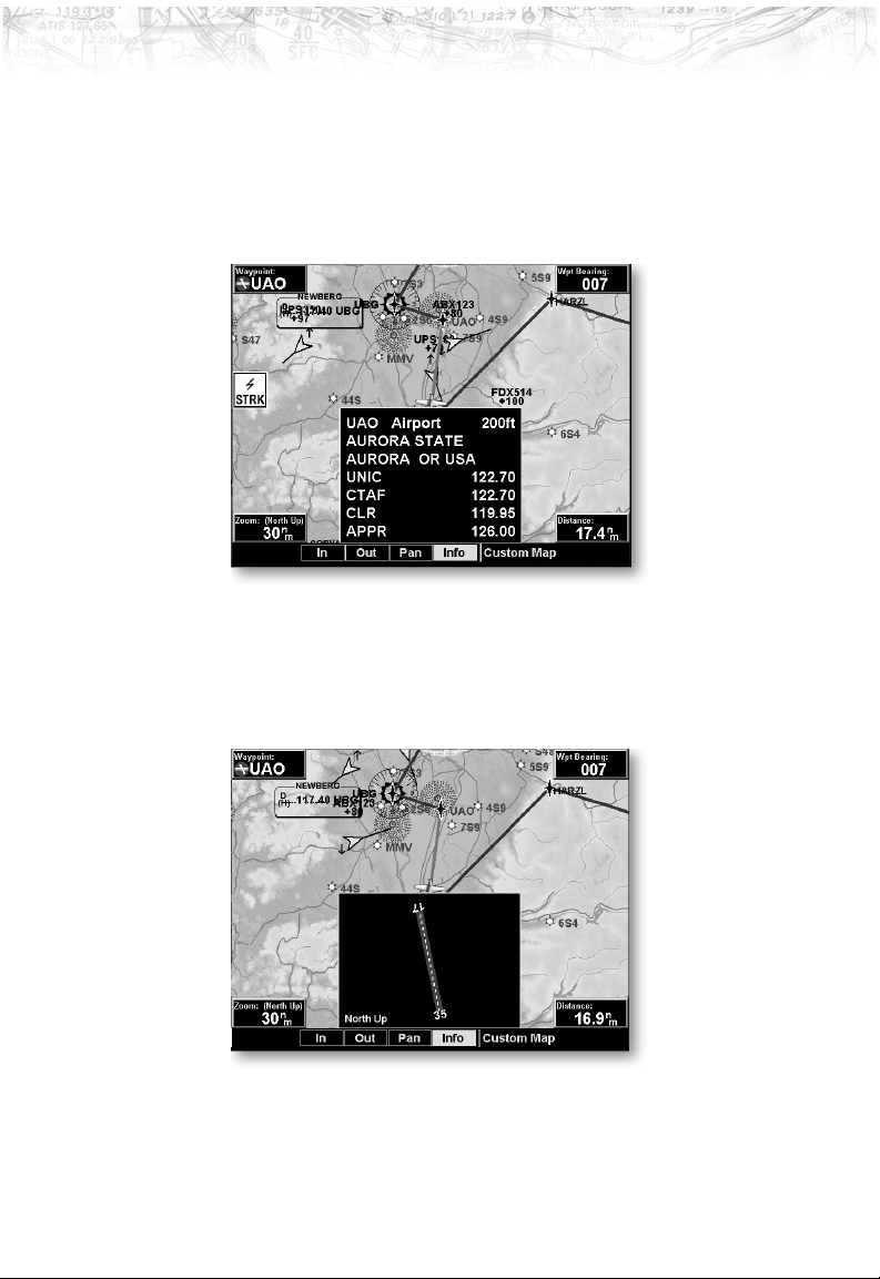
Info
Press the INFO “smart” key to view information about the
current “TO” waypoint.
Each press of the
INFO key will step through the available
information for the current destination waypoint. The
number of pages depends on the amount of information
about the destination waypoint.
Runway diagrams of airports will be displayed in the same
orientation as the main map (i.e., North Up, Track Up, or
DTK Up).
19
Page 30

Detailed Operation
Info In Pan Mode
The INFO smart key supports operation in conjunction
with the PAN feature.
On any of the maps (Custom Map, IFR and VFR),
entering the INFO mode while pan is active, will show
information about the nearest airport to the center of the
screen. This allows panning around the immediate area
and obtaining information about airports in the vicinity
without changing the current ‘TO’ waypoint.
While in this mode, both the PAN and INFO smart keys
are highlighted. Only information about airports can be
obtained with this feature.
20
Page 31
Detailed Operation
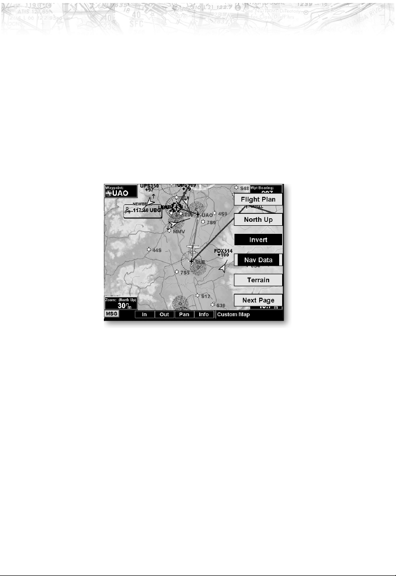
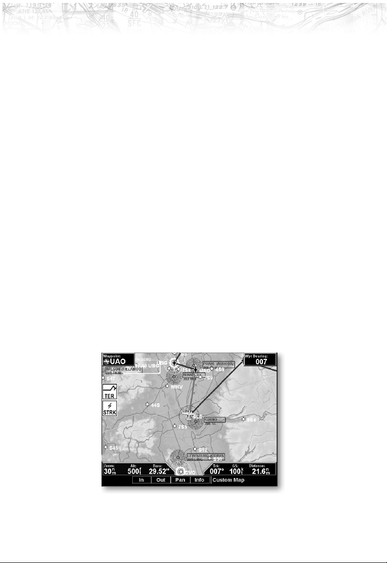
Custom Map Menu Option Page 1
The first option page of the Custom Map function lets you
select options for the choices of Flight Plan, map
orientation, Invert, Nav Data, and Terrain. The last
option selection takes you to the next page of options. The
options have tri-state choices that are also shown visually.
When the option is clear, the icons and labels are not
displayed. When the option is solid, icons and labels are
all shown. When the option box is partially filled, only the
icons are shown.
Flight Plan
The Flight Plan option controls the display of the Flight
Plan course line. Pressing the
the Flight Plan option toggles between showing or not
showing the Flight Plan route line.
LINE SELECT key next to
Map Orientation
This option controls the screen orientation in reference to
the aircraft symbol. You may select from North Up, Track
Up, Track Up Arc, Track Up 360, and Desired Track Up.
North Up sets magnetic north as the top of the screen.
Track Up sets the current track of the aircraft as the top
of the screen. Track Up Arc sets the current track of the
aircraft and a 120° arc at the top of the screen. Track Up
360 sets the current track of the aircraft at the top of the
21
Page 32
Detailed Operation
Invert
Nav Data
screen and a 360° ring with the aircraft symbol position in
the center. Desired Track Up sets the desired track to the
next waypoint as the top of the screen. Press the
SELECT
key next to this option to scroll through the
LINE
options.
The Invert option changes the display of text and the
background color. Depending on which layers are turned
on, inverting the display may help readability for the
current lighting conditions. For instance, when terrain is
shown, the Invert option switches between white and
black text. When terrain is turned off, the Invert option
switches between a white background with black text and
a black background with white text.
The Nav Data option allows to control the display of
navigation data on the display. Subsequent presses of the
LINE SELECT key for this option provides choices of no
nav data, nav data in the corners (waypoint, bearing,
zoom, and distance), or full nav data. The full nav data
option includes the information in the four corners
selection plus altitude, barometer setting, track, and
ground speed.
22
Page 33

Detailed Operation
Terrain
The Terrain option allows you select the display of
topographical features. Pressing the
next to the Terrain option toggles between sectional
(absolute), terrain awareness (relative), or no display of
topographical features. The sectional (absolute) display
shows a display similar to a sectional map. The terrain
awareness (absolute) display shows a color coded view
where the colors relate to terrain elevation relative to your
altitude. For more information about the terrain
awareness option, see the Terrain function section on
page 46. When you turn the Terrain feature off, the
background is either black or white depending on your
selection in the Invert option. When no terrain data is
available, the missing areas will be shown in light blue.
Water will not be shown in relative mode.
LINE SELECT key
Press the Next Page
page of menu items.
LINE SELECT key to display the next
23
Page 34
Detailed Operation
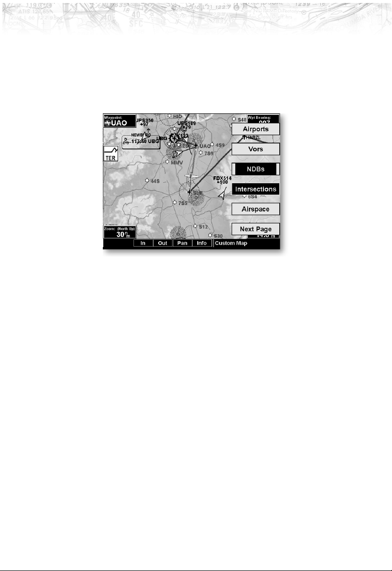
Custom Map Menu Option Page 2
Airports
The second option page of the Custom Map function lets
you select options for the choices of Airports, Vors, NDBs,
Intersections, and Airspace. The last option selection takes
you to the next page of options.
The Airports option allows you to choose the level of
airport information displayed on the Map screen. You
may select the display of airport icon and identifier, icon
only, or no information by each subsequent press of the
Airport
LINE SELECT option keys.
VORs
The VORs option allows you to choose the type of VOR
information displayed on the Map screen. You may select
the display of VOR icon and identifier, icon only, or no
information by each subsequent press of the VOR
SELECT
key.
The MX20 supports full integration with the Apollo SL30
Nav/Com. This feature allows tuned VORs along with
ILS and localizer approaches to be shown on the MX20
moving map. This high level of integration is designed to
provide additional, simple to interpret situational
awareness during high work-load phases of flight. The
graphic display of Nav/Comm information on the MX20
24
LINE
Page 35
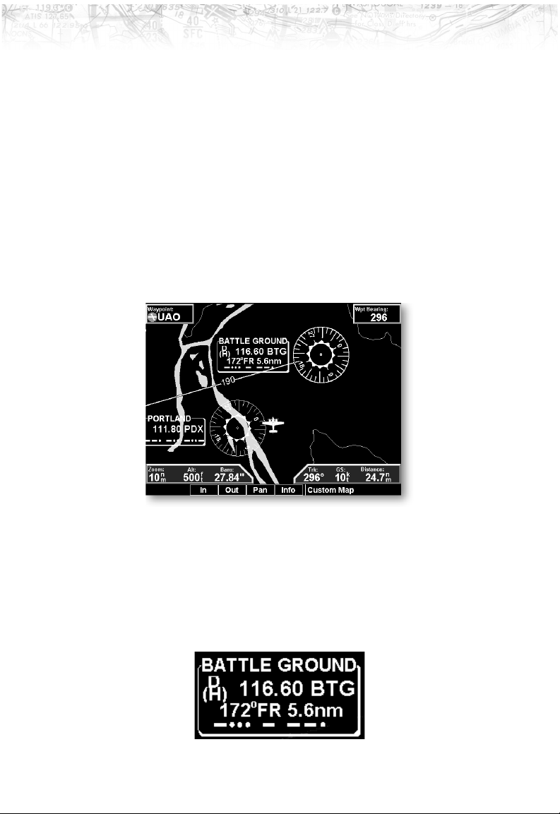
Detailed Operation
provides another source to help make sure you are using
the intended navigational aid and your To/From
orientation to the reference station is as desired.
You can turn the display of VOR and ILS information in
the Custom Map page on or off. VOR and ILS
information is always shown in the IFR and VFR Chart
functions.
VOR Highlight
The MX20 highlights the VOR in magenta on the moving
map when the SL30 is either tuned to or monitoring a
nearby VOR station. The highlighted VOR station is
determined by using the tuned or monitored VOR
frequency of the SL30 with the MX20 internal database.
The SL30 must be receiving a valid signal from the VOR.
The VOR information box for the selected VOR will show
the distance and radial-from bearing between your present
position and the VOR. The radial and distance information
comes from your GPS, not the SL30.
25
Page 36
Detailed Operation
The MX20 must have VOR symbols turned on for this
feature to be active in the Custom Map function. VOR
information is always shown in the IFR and VFR Chart
functions.
VOR OBS
The OBS (Omni-Bearing Selector) value selected in the
SL30 will be shown as a line from the tuned VOR station
in magenta on the MX20 display. The selected value will
be shown on the line. This feature provides a quick view
of your position relative to both the VOR and the tuned
radial to help improve situational awareness. The OBS
line will only be drawn from the active VOR, not the
monitored VOR.
The SL30 must be receiving a valid signal from the VOR and
the MX20 must have VOR symbols turned on for this feature
to be active.
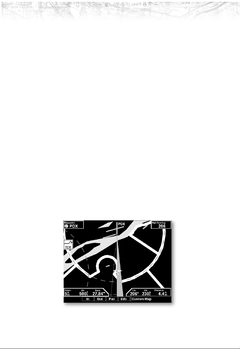
ILS/Localizer Depiction
When either an ILS or localizer is tuned on the SL30, the
MX20 will display the currently tuned approach on the
appropriate airport runway. The SL30 Nav function
provides an overall graphic view of the selected airport and
approach based on runway extensions and the selected
frequencies. The standard ILS symbol is shown in
magenta on the MX20 display.
26
Page 37

Detailed Operation
Back Course Display
The MX20 will draw the “front course” on its display
when a localizer frequency is tuned into the SL30. If you
enable the back course feature of the SL30, the MX20 will
then draw a “front course” graphic localizer extending
from the reciprocal runway.
The front course localizer graphic is shaded on the right
side. The back course localizer graphic is shaded on the
left side. Since the SL30 reverse-senses the needles, a
standard “chase the needle” approach may be made and
the “front course” localizer graphic is always used on the
MX20.
A published back course approach at the airport is not
necessary to enable this feature.
The SL30 must be receiving a valid ILS, or localizer, and the
MX20 must have airports turned on for this feature to be
active.
NDBs
The NDBs option allows you to choose the type of NDB
information displayed on the Map screen. You may select
the display of NDB icon and identifier, icon only, or no
information by each subsequent press of the NDB
SELECT
key.
LINE
Intersections
The Intersections option allows you to choose the type of
Intersection information displayed on the Map screen.
You may select the display of the Intersection icon and
identifier, icon only, or no information by each
subsequent press of the Intersection
LINE SELECT key.
27
Page 38
Detailed Operation
Airspace
The Airspace option allows you to control the display of
airspaces. Pressing the
LINE SELECT key next to Airspace
toggles between either the display of airspace boundaries
and altitude information, boundaries alone, or no display
of airspaces.
Press the Next Page
LINE SELECT key to display the next
page of menu items.
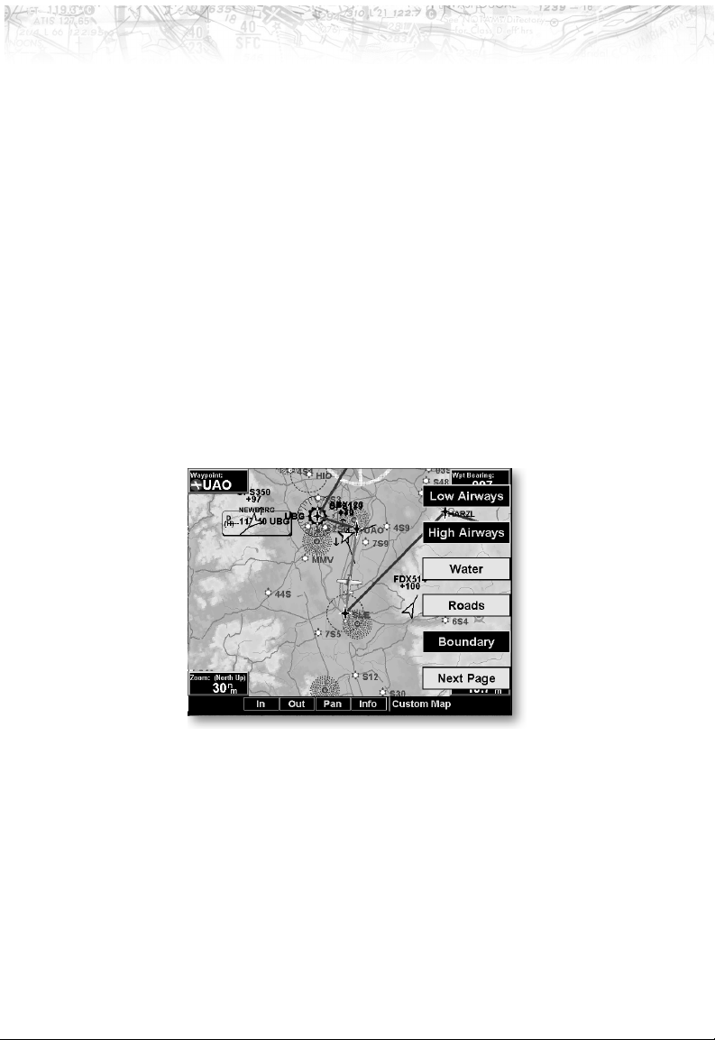
Custom Map Menu Option Page 3
The third option page of the Custom Map function lets
you select options for the choices of Low Airways, High
Airways, Water, Roads, and political boundaries. The last
option selection takes you to the next page of options.
Low Airways
The Low Airways option allows you to control the display
of Low Airways. Pressing the
Low Airways toggles between either the display of the
airway and label, airway alone, or no display of Low
Airways.
LINE SELECT key next to
28
Page 39
Detailed Operation
High Airways
The High Airways option allows you to control the
display of High Airways. Pressing the
LINE SELECT key
next to High Airways toggles between either the display of
the airway and label, airway alone, or no display of High
Airways.
Water
The Water option allows you to control the display of
rivers and lakes. Pressing the
LINE SELECT key next to
Waters toggles between either the display or no display of
the bodies of water.
Roads
The Roads option allows you to control the display of
interstate and state highways. Pressing the
LINE SELECT
key next to Roads toggles between either the display or no
display of the road features.
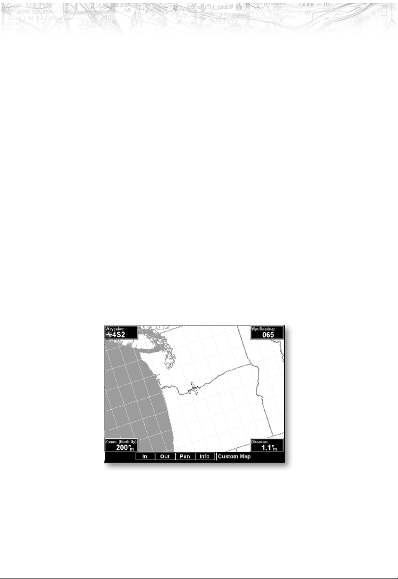
Boundary
The Boundary option allows you to select the display of
political boundaries on the Map displays.
Press the Next Page
page of menu items.
LINE SELECT key to display the next
29
Page 40
Detailed Operation
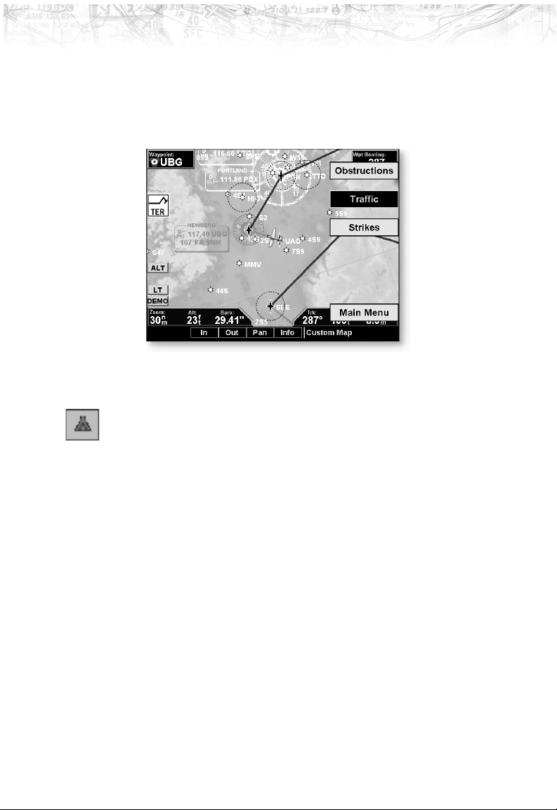
Custom Map Menu Option Page 4
Obstructions
The fourth option page of the Custom Map function lets
you select options for choices of Obstructions, Traffic, and
Lightning Strikes.
Obstructions, such as towers and other man-made objects,
are part of the MX20 updateable database. Obstructions
over 250 feet high are shown on the maps with tower
symbols. The symbol is color coded to signify the relative
altitude of the tower to your aircraft’s altitude. Objects
that are at your altitude are shown in red; objects that are
near your altitude are shown in yellow; objects with
towers that are significantly below your altitude colored
green. Obstructions are shown on the Custom Map and in
the Terrain function.
Current coverage for obstructions is North America only
and are drawn only when the zoom level is below 50nm.
Traffic
The Traffic option turns the display of traffic information
on or off. Traffic information includes the location and
identifier of a reporting aircraft, its direction of travel,
elevation, and the estimated path for the selected time
interval. See the section on the Traffic mode for more
details on how traffic information is used.
30
Page 41

Detailed Operation
The Traffic function is not available in all software
versions. Check your Approved Flight Manual
Supplement to verify if this feature is available.
Strikes
The Strikes menu option controls the display of lightning
strike information if the MX20 receives strike data from
an external source, such as the WX500. Each reported
lightning strike is shown as a red “x” on the display.
Strikes are not shown if the zoom level is below 20 nm.
Press the Next Page
page of menu items.
LINE SELECT key to display the next
31
Page 42
Detailed Operation
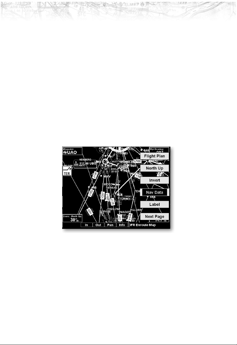
IFR Chart Function
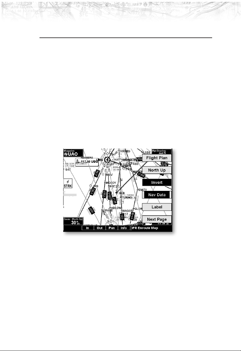
The IFR Chart function shows an IFR en route style map
for the display. The IFR display shows navigational aid
information and the flight plan course line. The “smart”
keys on the bottom of the screen control zooming in and
out, panning, and the display of information on the
current TO waypoint. The menu of options available for
the IFR mode include Flight Plan, map orientation,
Invert, and turning labels on or off.
IFR Option Page 1
The first option page of the IFR Chart function lets you
select options for the choices of Flight Plan, Map
Orientation, Invert display, Nav Data, and Labels. The
last option selection takes you to the next page of options.
Flight Plan
The Flight Plan option controls the display of the Flight
Plan course line. Pressing the
the Flight Plan option toggles between showing and not
showing the Flight Plan route line.
LINE SELECT key next to
Map Orientation
This option controls the screen orientation in reference to
the aircraft symbol. You may select from North Up, Track
Up, Track Up Arc, Track Up 360, and Desired Track Up.
32
Page 43
Detailed Operation
North Up sets magnetic north as the top of the screen.
Track Up sets the current track of the aircraft as the top
of the screen. Track Up Arc sets the current track of the
aircraft and a 120° arc at the top of the screen. Track Up
360 sets the current track of the aircraft at the top of the
screen and a 360° ring with the aircraft symbol position in
the center. Desired Track Up sets the desired track to the
next waypoint as the top of the screen. Press the
SELECT
key next to this option to scroll through the
options.
Invert
The Invert option changes the display of text and the
background color. The Invert option switches between a
white background with black text and a black background
with white text.
LINE
Nav Data
The Nav Data option allows you to control the display of
navigation data on the Map displays. Subsequent presses
LINE SELECT key for this option provides choices of
of the
no nav data, nav data in the corners (waypoint, bearing,
zoom, and distance), or full nav data. The full nav data
option includes the information in the four corners
selection plus altitude, barometer setting, track, and
ground speed.
33
Page 44
Detailed Operation
Label
IFR Option Page 2
The LABEL key turns the labels for each item on or off for
easy decluttering. When Labels are turned off, only the
identifier for waypoints along the flight plan will remain
in view when the flight plan is enabled.
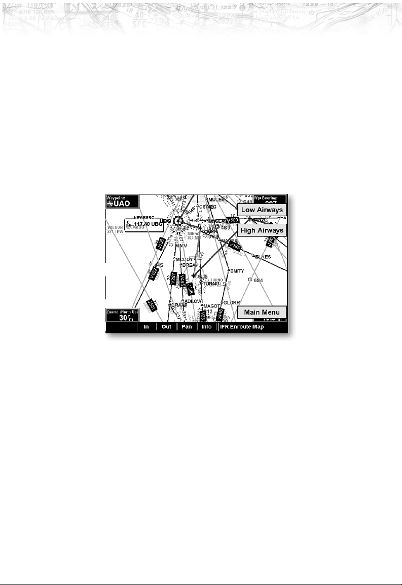
The second option page of the IFR Chart function lets
you select options for the choices of Low Airways, and
High Airways. The last option selection takes you back to
the first page of options.
Low Airways
The Low Airways option allows you to control the display
of Low Airways. Pressing the
Low Airways toggles between either the display of the
airway and label, airway alone, or no display of Low
Airways.
LINE SELECT key next to
High Airways
The High Airways option allows you to control the
display of High Airways. Pressing the
next to High Airways toggles between either the display of
the airway and label, airway alone, or no display of High
Airways.
34
LINE SELECT key
Page 45
VFR Chart Function
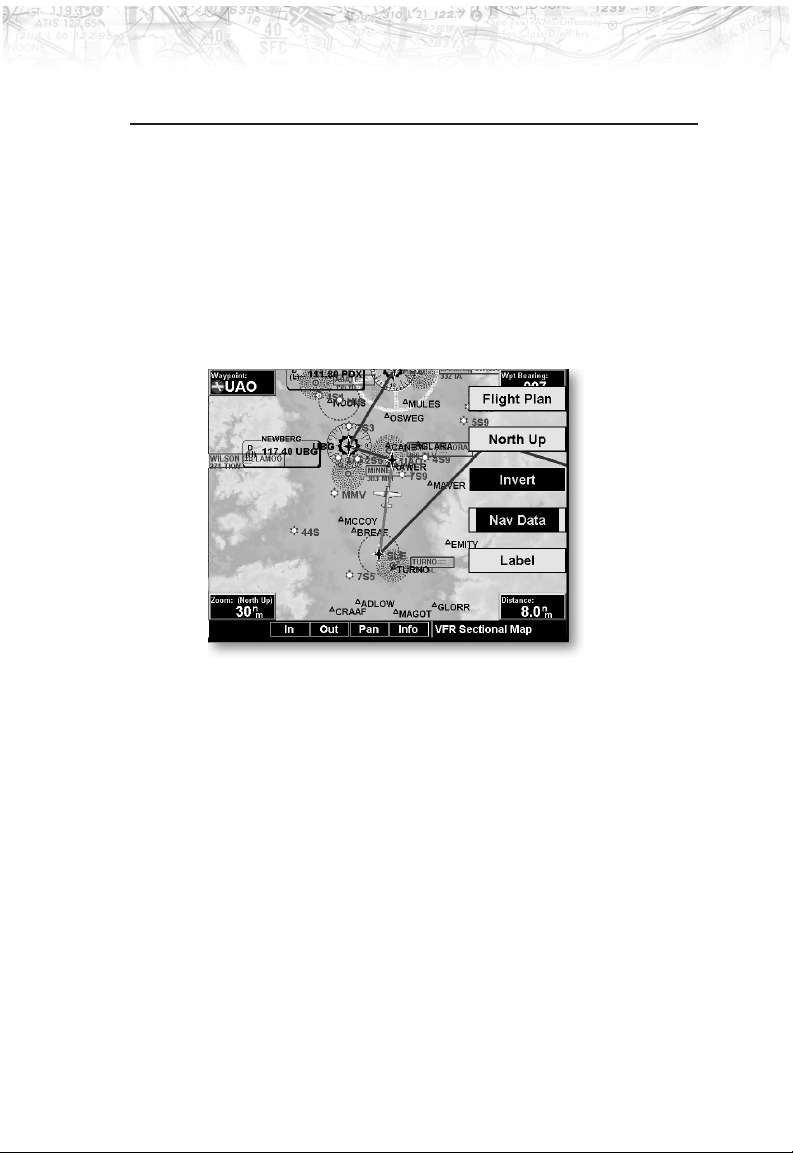
The VFR Chart function shows an VFR sectional style
map for the display. Topographic features are shown. The
VFR display shows navigational aid information and the
flight plan course line. The “smart” keys on the bottom of
the screen control zooming in and out, panning, and the
display of information about the current TO waypoint.
The options available for the VFR mode include Flight
Plan, screen orientation, Invert, and turning labels on or
off.
Detailed Operation
Flight Plan
The Flight Plan option controls the display of the Flight
Plan course line. Pressing the
the Flight Plan option toggles between showing and not
showing the Flight Plan route line.
LINE SELECT key next to
Map Orientation
This option controls the screen orientation in reference to
the aircraft symbol. You may select from North Up, Track
Up, Track Up Arc, Track Up 360, and Desired Track Up.
North Up sets magnetic north as the top of the screen.
Track Up sets the current track of the aircraft as the top
of the screen. Track Up Arc sets the current track of the
aircraft and a 120° arc at the top of the screen. Track Up
35
Page 46

Detailed Operation
Invert
Nav Data
360 sets the current track of the aircraft at the top of the
screen and a 360° ring with the aircraft symbol position in
the center. Desired Track Up sets the desired track to the
next waypoint as the top of the screen. Press the
SELECT
key next to this option to scroll through the
LINE
options.
The Invert option changes the text and background color.
Inverting the display may help readability for the current
lighting conditions and the color of the terrain in a given
area.
The Nav Data option allows to control the display of
navigation data on the Map displays. Subsequent presses
LINE SELECT key for this option provides choices of
of the
no nav data, nav data in the corners (waypoint, bearing,
zoom, and distance), or full nav data. The full nav data
option includes the information in the four corners
selection plus altitude, barometer setting, track, and
ground speed.
Label
The LABEL key turns the labels over each item of
information on or off. When Labels are turned off, only
the identifier for waypoints along the flight plan will
remain in view when the flight plan is enabled.
36
Page 47
Traffic Function
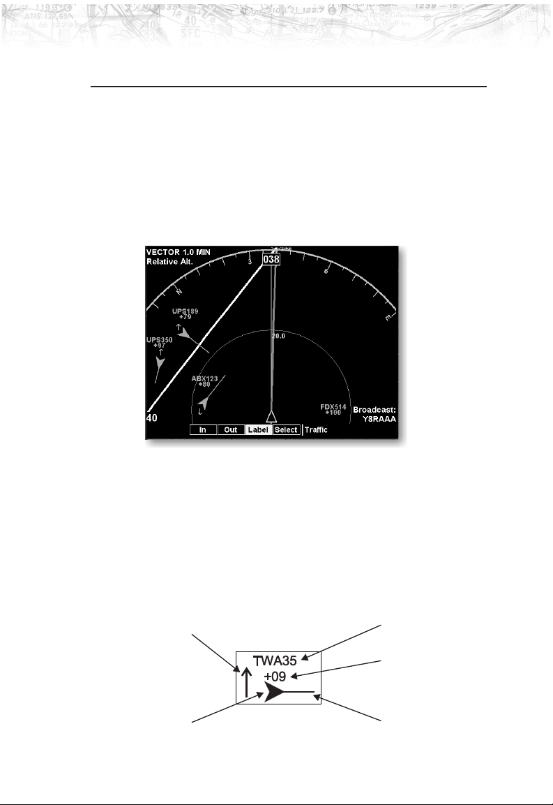
The Traffic Function allows you to view other traffic in
the area. This screen can also show your flight plan.
Traffic is shown in relationship to your aircraft. “Smart”
keys allow you to zoom in and out, show traffic labels, and
select an individual traffic target. The Traffic function is
not available in all software versions. Check your
Approved Flight Manual Supplement to verify if this
feature is available.
Detailed Operation
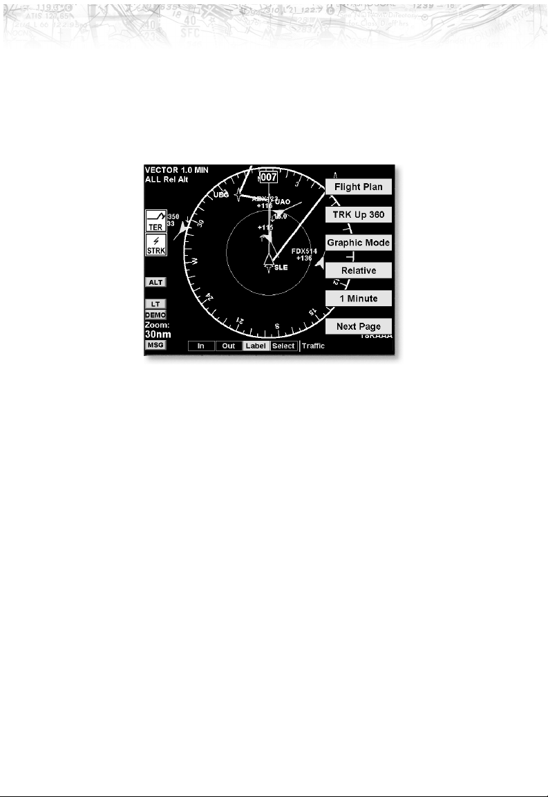
Traffic Description
Your position (ownship symbol) is located at the tip of the
empty triangle. The other traffic is shown as a large solid
cyan (light blue) arrow pointing in its direction of travel.
Next to the traffic arrow symbol is the traffic identifier,
and altitude. Altitude is selected as either Pressure or
Relative as noted in the upper left corner of the display. A
Traffic climb rate
greater than
500 ft/min
Traffic Identifier
Traffic Relative or
Pressure Altitude
Traffic vectorTraffic Icon
37
Page 48

Detailed Operation
r
small up or down arrow next to the identifier indicates
that the traffic is climbing or descending at a rate of at
least 500 feet per minute. The end of the vector line that
extends beyond the point of the traffic arrow indicates
where it will be at the end of the selected time interval.
The currently selected time interval is indicated in the
upper left corner of the display.
TIS-B Traffic
Traffic Information Service – Broadcast (TIS-B) is
supported by displaying non ADS-B equipped aircraft
that are received over the UAT data link radio. Non
ADS-B equpped aircraft that are detected by ground
based radar can be up-linked to all aircraft in the area that
are ADS-B/data link equipped.
TIS-B Target Traffic Vecto
TIS targets act and behave similar to actual ADS-B traffic
targets, except that the target symbol is a rounded nose
target.
As TIS target location is determined by ground based
radar, coverage, range and target positional accuracy are
highly dependent on relative location to the actual radar
site.
Target Color
Targets that are on the ground are colored in tan. Targets
that are airborne are cyan in color.
Surface Targets
Surface targets, in addition to ADS-B targets, are
supported and are shown as tan, rectangular ICONs.
38
Page 49

Detailed Operation
They are displayed both on the Traffic Function page,
and on the Custom Map when traffic is turned on.
Surface Target
Operation
The controls at the bottom of the screen allow you to
zoom in and out, turn the traffic identifiers on/off (Label),
and to select each traffic target on the screen.
1. Press the
the
2. Press
3. Press the
FN key to reach the Function page showing
TRAF “smart” key.
TRAF (Traffic).
IN key to zoom in. Press the OUT key to zoom
out.
4. Press the
LABEL key to turn the Identifier over each
Traffic item on or off.
5. Press the
SELECT key to step through each Traffic item
that is shown on the display. When a target is selected,
additional information about that target is shown in the
upper right corner of the display. The selected target
will be highlighted in green on the display. Surface
targets cannot be selected.
39
Page 50
Detailed Operation
Traffic Option Page 1
Flight Plan
The first option page of the Traffic function lets you select
options for the choices of Flight Plan, Traffic Map
Orientation, Display mode, Altitude, and Time. The last
option selection takes you to the next page of options.
The Flight Plan option controls the display of the Flight
Plan course line. Pressing the
the Flight Plan option toggles between showing and not
showing the Flight Plan route line.
LINE SELECT key next to
Traffic Map Orientation
The Traffic Map Orientation option lets you choose
between a 360-degree compass rose or an arc that covers
about 90 degrees over the top of the display. Your aircraft
position is shown by an empty white triangle near the
center of the display. The Traffic function display is
always in the Track Up mode.
40
Page 51
Detailed Operation
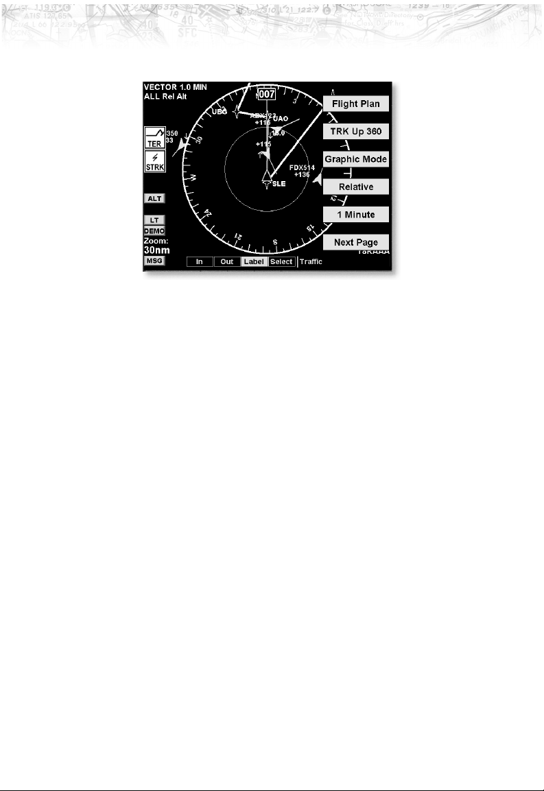
Traffic Altitude Values
Altitudes shown next to the traffic icon are in hundreds of
feet (09 = 900 feet). Altitude values shown in all other
locations and displays are the actual values in feet (+100
= 100 feet).
Display Mode
The display mode lets you select either a graphic or text
version of traffic information.
Graphic
The graphic traffic display shows your location, nearby
traffic, and information about the traffic.
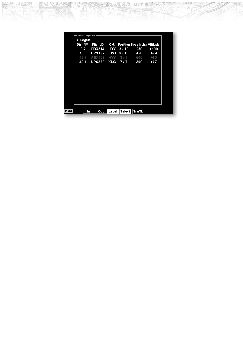
Text
The text traffic display shows the distance to the traffic
item, flight id, category, position, speed, and altitude. The
currently selected target is shown in green. The traffic list
is sorted by distance with the closest traffic to your current
position shown on the top line. The total number of
targets tracked is shown in the upper left corner. Up to 12
of the nearest targets are listed.
41
Page 52
Detailed Operation
Altitude Option (Relative/Pressure)
The altitude option lets you select between relative and
pressure altitude in hundreds of feet. The altitude option
choice is shown on the upper left corner of the screen
while in the graphic display option. When Relative
Altitude is selected, the altitude value on the traffic is
shown relative to your altitude. A “+” indicates the target
is above your altitude. A “-” indicates the target is below
your altitude. For instance, if a value of +80 is shown, the
value means that the indicated traffic is 8000 feet above
your altitude. When Pressure Altitude is selected, if a
value of 121 is shown, the value means that the indicated
traffic is at 12,100 feet pressure altitude. Pressure altitude
does not showa+or-.Remember that pressure altitude
can be substantially different than the baro-corrected
altitude shown on the altimeter in your aircraft.
Time
The time interval option sets the amount of time to
estimate the path and location of the traffic. The path of
the traffic is shown by the line extending from the point
on the end of the traffic arrow icon. The end of the line
shows the point where the traffic item will be at the end of
the selected time interval. Select 1, 1.5, 2-5, or 10 minutes.
Press the Main Menu
next page of menu items.
42
LINE SELECT key to display the
Page 53
Detailed Operation
Traffic Option Page 2
The second option page of the Traffic function lets you
select options for the choices of Broadcast ID and Flight
ID Editing. The last option selection takes you back to the
first page of options.
ADS-B Broadcast Mode Control
For ADS-B equipped installs, this feature allows the pilot
to control the broadcast mode of their aircraft.
Broadcast options are controlled via the Traffic Function
Menu and allow the pilot to toggle between ‘Broadcast
FID / Broadcast VFR / Standby’.
Broadcast FID
Causes the currently set Flight ID and permanently
assigned ICAO address to be broadcast with the aircraft’s
current position. The Flight ID is pilot settable via the
menu option ‘Enter FID’, while the ICAO address is set
during system install.
Broadcast VFR
Causes a fixed Flight ID of ‘VFR’ and a randomly
generated ICAO address to be broadcast with the aircraft’s
current position. This mode is similar to anonymously
squawking ‘VFR 1200’ on a standard transponder.
43
Page 54
Detailed Operation
Flight ID Editing
Standby
Causes the transmit function of ADS-B to enter the
standby mode. Other aircraft can be seen, but no data is
transmitted. This mode is similar to setting a standard
transponder to the ‘standby’ mode.
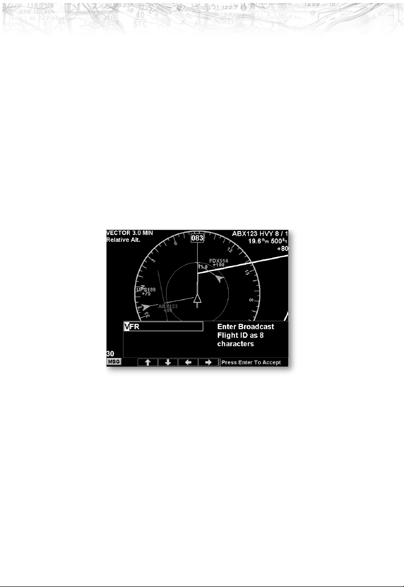
The Enter Flight ID option allows you to edit your
broadcasted Flight ID. The Function “smart” keys at the
bottom of the screen change to arrow keys. Use the
UP/DOWN arrow keys to change the characters. Use the
LEFT/RIGHT arrow keys to move between characters. Press
the
MENU/ENTER key to save the displayed Flight ID. The
Flight ID is only sent when the Flight ID broadcast
option is enabled.
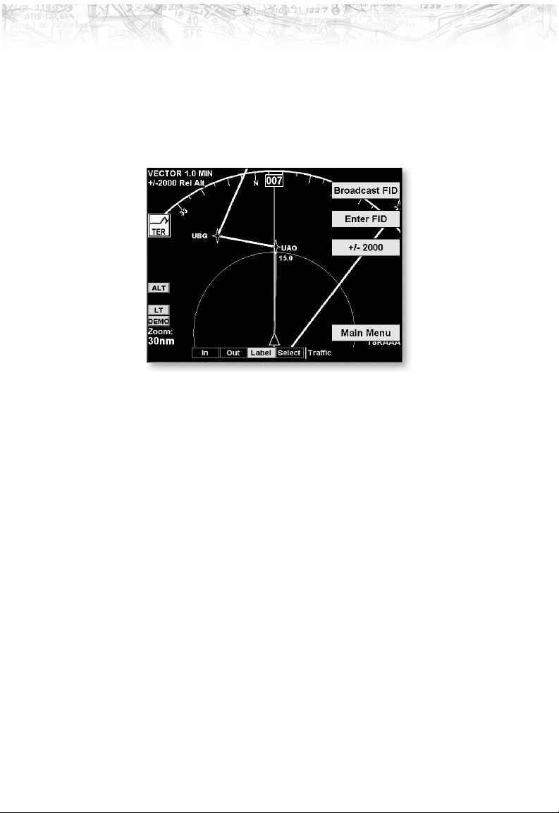
Traffic Altitude Filter
For ADS-B equipped installs, an altitude filter allows
targets that are outside of a +/-2000’ vertical range to be
filtered off the display.
This option is controlled via the Traffic Function Menu
and causes the on-screen mode to change from ‘ALL’ to
‘+/-2000’ in the upper left of the Traffic Function screen.
In the ‘ALL’ mode, all targets, regardless of their altitude,
are shown. In +/-2000’ mode, only targets that are within
2000’ above or below the ownship altitude are shown.
44
Page 55
Flight Plan (FPL) Function
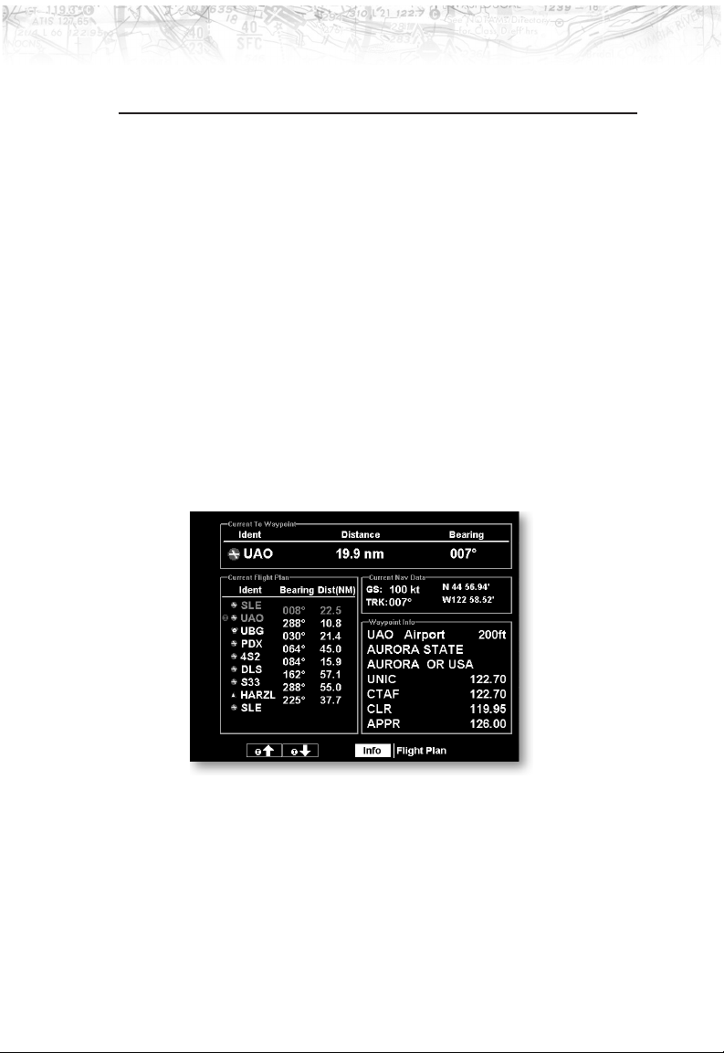
Use the Flight Plan function to view details about your
flight plan route. Press the
to step through the waypoints in your flight plan. Press
INFO “smart” key to view information about the
the
waypoint. The Flight Plan Function shows the Current
Flight Plan that is active in the connected navigation
source (i.e. GPS receiver). The Current To Waypoint box
shows the current leg of the flight plan. The Current
Flight Plan box shows all of the legs of your flight plan
with the current leg indicated in magenta. Listed are each
leg with the bearing and distance between the legs. The
Current Nav Data box shows the aircraft current position
in latitude and longitude, ground speed, and track. In the
lower right corner information for the current waypoint is
displayed in the Waypoint Info box. The Flight Plan
function does not have any options.
UP/DOWN arrow “smart” keys
Detailed Operation
Runway diagrams of airports will be displayed in the same
orientation as the main map (i.e., North Up, Track Up, or
DTK Up).
45
Page 56
Detailed Operation
Terrain (TER) Function
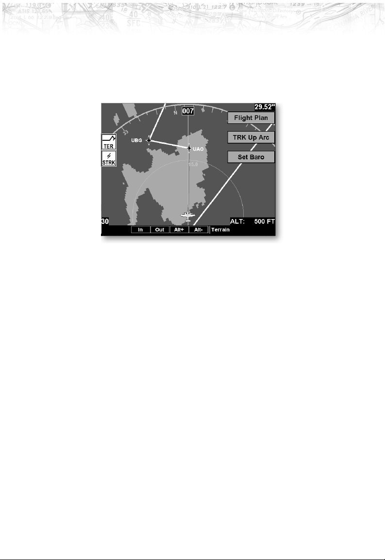
The Terrain Function shows a map of the terrain in the
area relative to your airplane’s position and altitude. The
altitude information comes from an external altitude
encoder. The displayed altimeter setting has to be
adjusted, or baro-corrected, just like the one in your
aircraft’s instrument panel.
The terrain screen has a 360-degree and a 90-degree
display. Both screens will show terrain relative to your
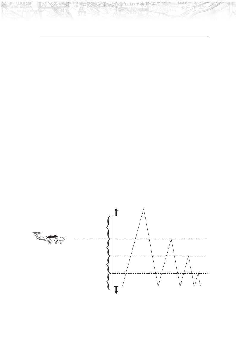
position. Colors used for terrain display are shown below.
The Terrain function shows you the general
terrain elevations relative to your altitude
and are advisory in nature. Individual
obstructions may be shown if available in
the database. Terrain is displayed from
database information and may therefore
potentially contain some degree of error. Do
not use this information for surface or
primary navigation.
Note
Current Altitude
500 feet below your current altitude
2000 feet below your current altitude
More than 2000 feet below your current altitude
46
Highest Terrain
Red
Yellow
Green
Black
Page 57
Detailed Operation
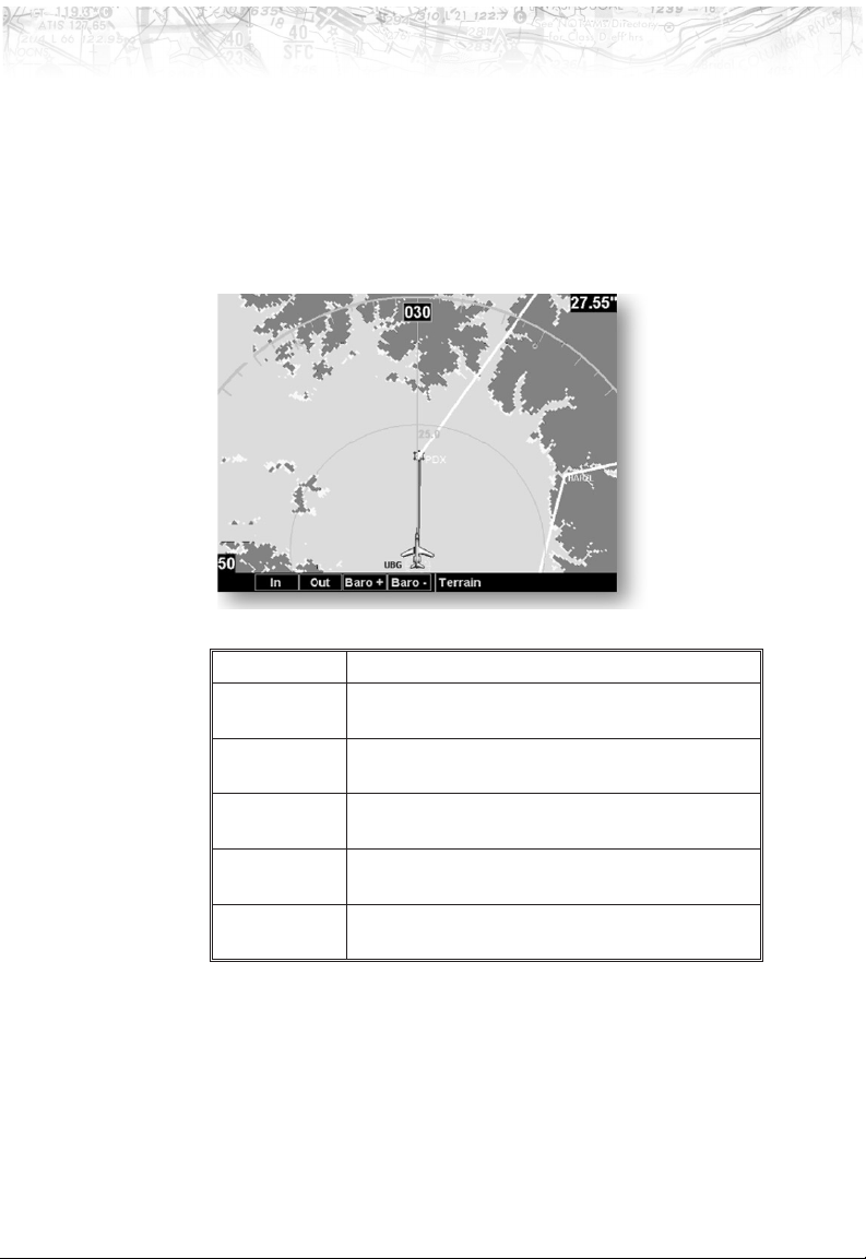
Use the IN and OUT keys at the bottom of the screen to
zoom in and zoom out. The zoom range is shown in the
lower left corner of the screen.
Use the
BARO+ and BARO- keys at the bottom of the
screen to make minor adjustments to the barometric
pressure value.
Color Description
RED Terrain that is at, or above, your current
altitude
YELLOW Terrain that is within 500 feet of your current
altitude
GREEN Terrain that is within 2000 feet of your
current altitude
BLACK Terrain that is more than 2000 feet below
your current altitude
LIGHT
BLUE
No terrain data is available
47
Page 58
Detailed Operation
Terrain Option Page
Flight Plan
The Terrain option page lets you select options for the
choices of Flight Plan, Map Orientation, and setting the
barometric pressure.
The Flight Plan option controls the display of the Flight
Plan course line. Pressing the
LINE SELECT key next to
the Flight Plan option toggles between showing and not
showing the Flight Plan route line.
48
Page 59
Detailed Operation
TRK Up Arc/TRK Up 360
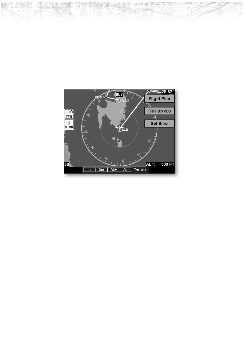
This ring is marked in nautical miles from your airplane
with the ring placed at one half the distance of the map
scale. For instance if you have the map scales at 50 miles,
the ring will be at 25 miles. The ring will change
automatically as you change the map scale. The Terrain
function display is always in the Track Up mode.
Set Barometer
Use the Set Barometer option to enter the correct
barometric pressure for your area or adjust the current
value. Use the
decrease the values. Use the
move between characters. Press the
UP/DOWN arrow keys to increase or
LEFT/RIGHT arrow keys to
ENTER key to save the
displayed barometric pressure.
A “Confirm Current Baro” message is displayed at the
initial power-up and again once every 30 minutes of
operation as a reminder to check your baro setting.
TER Data Flag
The TER flag will appear if no terrain data is available
for the advisory coverage area.
49
Page 60
Detailed Operation
Weather (WX) Data Link
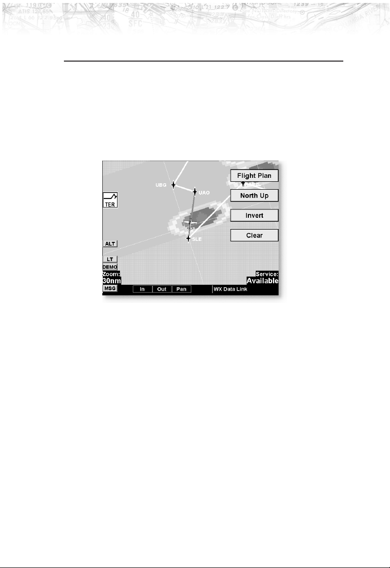
The WX Data Link Function is capable of displaying
graphical weather information on UAT equipped
installations. Graphical data is overlaid on the map
indicating the rainfall detected by ground based radar for
a specific area. The colors indicating increasing levels of
rainfall progresses from light green for light rainfall to
magenta for heavy rainfall.
Rainfall data is color coded as follows:
Brown/Blue Zero rainfall (transparent color)
Light Green Light rainfall
Dark Green V
Yellow V
Amber V
Red V
Magenta Heavy rainfall
Cyan No rainfall data available
A cyan checkerboard pattern indicates that no data is
available for area, and that area may contain any rainfall
levels.
When weather data is received, the airborne system will
display that data for 20 minutes, or until the power is
cycled. If no new data has been received for a given area,
50
Page 61

Detailed Operation
the rainfall will be removed and the area will revert back
to the cyan checkerboard pattern.
The WX Data Link Function is based on a ground-to-air
data link and requires that the appropriate ground systems
are broadcasting weather data and the aircraft is within
reception range of the ground broadcast transceiver
(GBT).
If any weather data has been received in the previous two
minutes, the ‘Service’ indicator in the lower left of the
screen will display ‘Available’. If no data has been
received in this time period, ‘Not Available’ will be shown.
This indicator shows if the aircraft is currently within
reception coverage of a ground station with weather
broadcast capabilities.
The ground system determines the weather coverage area
and extent of data that is transmitted by each ground
station. The MX20 will display any weather received for
the entire world.
51
Page 62
Detailed Operation
Flight Information Service-Broadcast
(FIS-B)
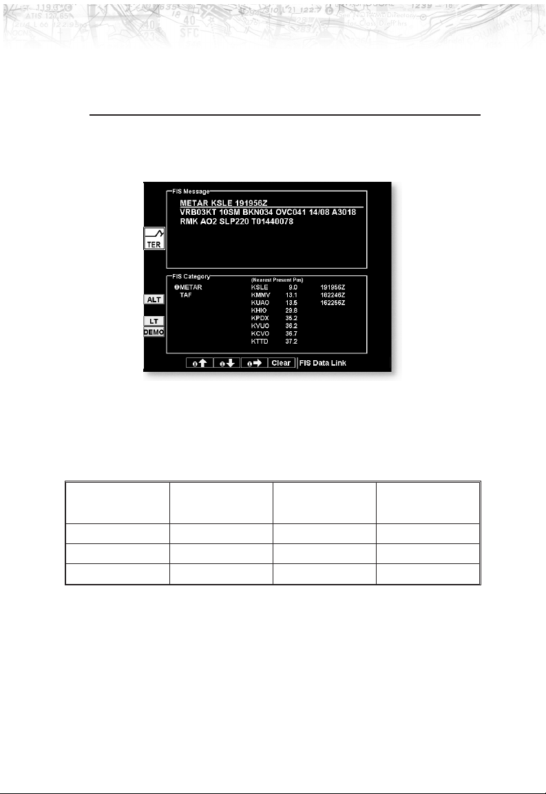
Flight Information Service - Broadcast (FIS-B) Function
allows access to textual weather data messages on UAT
equipped installations.
Individual FIS textual messages are composed of four
parts: message type, location, time and message body.
Examples:
TYPE LOCATION TIME MESSAGE
BODY
METAR KSLE 191534Z METAR TEXT
METAR KMMV 181423Z METAR TEXT
TAF KSLE 171423Z TAF TEXT
The upper portion of the FIS Function page is used for
displaying the contents of an individual FIS message
while the lower portion of the screen is used for
categorization and sorting of different message types, such
as METARS, TAFs, SIGMETS, etc.
The lower portion of the screen is divided into three
distinct columns to provide simple categorization of
52
Page 63

Detailed Operation
received textual messages. The columns are loosely
defined as message type, location and timestamp to
handle the most common type of FIS up-link data.
The different message types and data content are fully
controlled by the ground broadcast systems. The airborne
system will automatically display any message type that is
received.
Navigating the Displayed Data
By default, the system will show the nearest and most
recent weather report.
A green colored ‘Selection Pointer’ can be used to select
an alternative message for display. The pilot is able to
move the green Selection Pointer within the lower portion
of the page to select the desired category, location and
time that is of interest.
Using this interface, the pilot can easily select the desired
message type (such as METAR), then select the airport of
interest (such as KPDX), then select a specific METAR
report by time (such as 141512Z).
At all times, the message displayed in the upper FIS
Message area on the screen matches the highlighted entry
in the FIS Category area below.
Smart Key Function
The fourth smart key performs special functions within
the FIS Function:
When the Selection Pointer is located in the first of the
three columns, the fourth smart key displays the label
‘Clear’. When pressed, all messages for the currently
selected category will be flushed from the MX20. This
feature can be used to clear old, bad or corrupted data
received over the data link.
53
Page 64

Detailed Operation
Sorting FIS Messages
When the Selection Pointer is in the center most column,
the fourth smart key displays the label ‘Sort’. See below
for how the sort option works.
When the Selection Pointer is in the right most column,
the fourth smart key displays the label ‘View’. When
pressed, the currently viewed message is presented in a
full screen mode. This feature provides a mechanism to
view large textual messages that do not fit within the
upper half of the display area.
Special sorting capabilities are provided for in the central
‘location’ column. This sorting allows weather reports to
be sorted by location based on distance to airports in the
area.
When the green Selection Pointer is located in the second
column, the fourth smart key changes to read ‘Sort’.
When consecutively pressed, the sorting of the messages
toggle with the following options:
(Distance to) Nearest Present Position
(Distance to) Nearest Final Waypoint
(Distance to) Nearest Next Waypoint Alpha
As the sorting is based on distances from current ownship
to a given airport, the system must be able to correlate a
Jeppesen airport that matches the location field of the
received message. If this lookup is successful, a distance
shall be presented adjacent to the location text. If no
corresponding location can be determined, no distance
shall be assigned but the message shall still be presented at
the end of the list.
The default sorting method is ‘Nearest Present Position’
and is reset when the FIS Function is re-entered.
54
Page 65
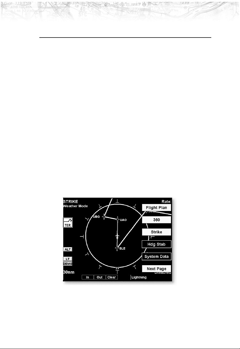
Detailed Operation
Lightning Strikes (LT) Function
The Lightning Strike mode allows you to view lightning
strikes that are reported by a BF Goodrich WX500
Stormscope Weather Mapping Sensor. The “T” marks are
used as reference marks to aid in locating strikes in
reference to your position. The Lightning function is not
available in all software versions. Check your Approved
Flight Manual Supplement to verify if this feature is
available. Your display range must be selected to be
greater than 25 nm to display lightning strikes. The
display range is shown in the lower left corner of the
display. For instance, if you zoom In to a range of 20 nm,
no strikes will be shown, but if you zoom Out to 30 nm
strikes will be shown.
Lightning Menu Option Page 1
The first option page of the Lightning function lets you
select options for the choices of Flight Plan, Display view,
Lightning groups, Heading Stabilization, and Stormscope
(System Data) info. The last option selection takes you to
the next page of options.
55
Page 66

Detailed Operation
Flight Plan
360/120
Lightning
The Flight Plan option controls the display of the Flight
Plan course line. Pressing the
the Flight Plan option toggles between showing and not
showing the Flight Plan route line.
Two display views of the lightning information may be
selected. The 360 view shows a 360° view the airspace
surrounding your aircraft. The 120 view shows a 120°
forward view from your aircraft’s position and the display
is divided into three segments.
The WX500 detects electrical discharges within a range
determined by the installation of your Stormscope. These
discharge locations are noted as Lightning strikes and
displayed as a red “x.” You may select either single strike
or cell (groups)of lightning representations.
LINE SELECT key next to
Strike
Individual strikes are noted.
Cell
Only lightning strikes associated with a group, or cell, of
strikes are displayed.
Heading Stabilization
The Heading Stabilization function of the WX500 can be
turned on or off with this selection.
System Data
Select the System Data option to display information
about the WX500.
Press the Next Page
page of menu items.
56
LINE SELECT key to display the next
Page 67
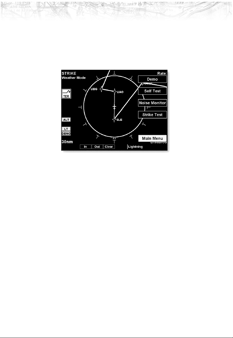
Detailed Operation
Lightning Menu Option Page 2
The second option page of the Lightning function lets you
select options for the choices of Demo, Self-Test for the
Stormscope, Noise Monitor, and Strike Test. The last
option selection takes you back to the first page of options.
Demo
The Demo option places the WX500 sensor in a
demonstration mode that simulates lightning strikes.
Self-Test
The Self-Test option performs a number of tests on the
operation of the WX500 and provides a report of its status.
Noise Monitor
The Noise Monitor feature is a function of the WX500.
For details about using this feature refer to the WX500
owner’s documents.
The Noise Monitor displays reports of electrical noise,
whether they are from lightning or other noise sources
within the range of the system. This function is used to
help determine if electrical noise is present that may affect
normal system operation.
57
Page 68

Detailed Operation
Strike Test
The Strike Test feature is a function of the WX500. For
details about using this feature refer to the WX500
owner’s documents.
The Strike Test feature is used by installers to verify
proper operation of the WX500. Test strikes are sent to
the antenna. The received test strike is then visually
presented on the screen.
58
Page 69
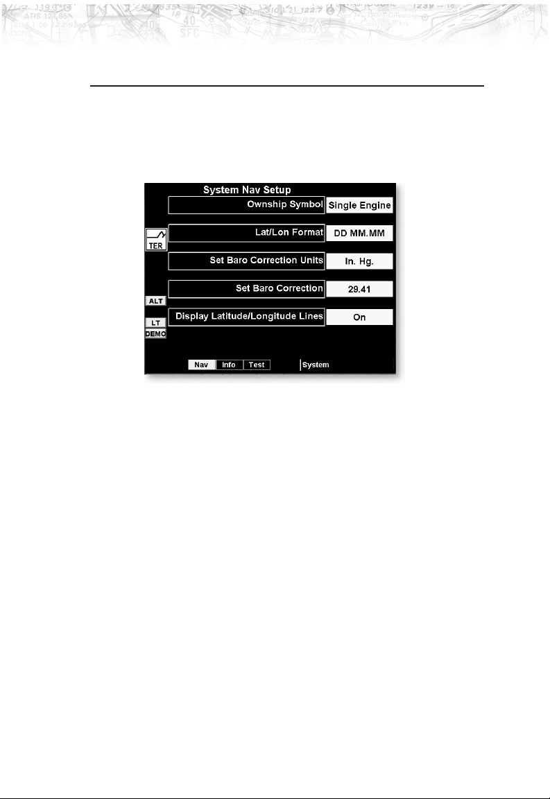
System Function
The System function allows you to set general Nav
preferences, obtain version information, and perform tests
on the operation of your MX20.
System Nav Page
Ownship Symbol
The Ownship Symbol option allows you to choose the
type of icon that will represent your aircraft on the display.
You can make selections of Single, Twin, Jet, or
Helicopter .
Lat/Lon Format
The Lat/Lon format option allows you to select between
two choices for the display of Lat/Lon coordinates.
Choose between degrees-minutes-seconds-seconds
decimals (DD MM SS.SS) or degrees-minutes-minutes
decimals (DD MM.MM).
Set Baro Units
Baro-Correction (QNH) can now be entered in Millibars
in addition to Hg. This preference is set under the SYS
function.
Detailed Operation
59
Page 70
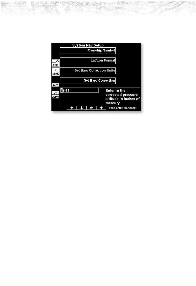
Detailed Operation
Set Baro Correction
You may enter the corrected barometric pressure so that
the proper pressure altitude will be displayed.
1. Press the
LINE SELECT key for Set Baro Correction.
2. The Function “smart” keys at the bottom of the display
will have direction arrows above them. Press the
UP/DOWN arrow keys to change the value of the
highlighted number. Press the
LEFT/RIGHT arrow keys
to move to another number.
3. Press
MENU/ENTER to save the changed values and
leave the Set Baro Correction option.
Display Lat/Lon Lines
Use this option to choose to display or not display Lat/Lon
lines on the map displays.
60
Page 71
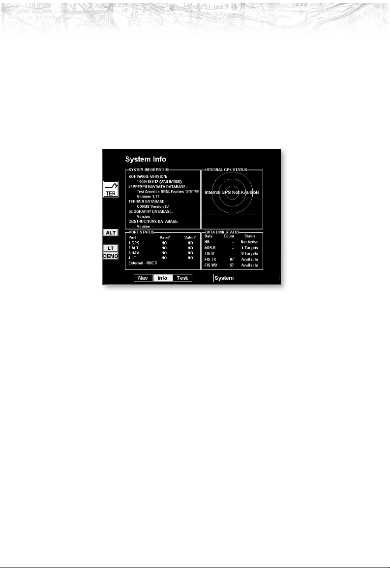
Detailed Operation
System Info
The System Info page includes information about the
software and database versions of the MX20. The data
port status is also displayed. The Data port status
description allows you to verify correct system installation
and to monitor the health of each of the devices sending
information to the MX20. Use this information when you
contact your dealer or the factory.
GPS and Datalink Status
For GPS/UAT equipped installs, the SYS/INFO page
now shows additional details for both the internal GPS
engine and the data-link status.
GPS satellite usage and signal strength are presented in
the upper right of the info page in addition to each
satellite’s position in the sky. If no GPS is installed in the
MX20, the text ‘Internal GPS Not Available’ will be
shown.
Data-link information is monitored as follows:
HB Heart-Beat from the UAT data-link radio
ADS-B ADS-B broadcast packets received
TIS-B TIS-B broadcast packets received
FIS TX Textual weather data packets received
FIS WX Graphical weather data packets received
61
Page 72
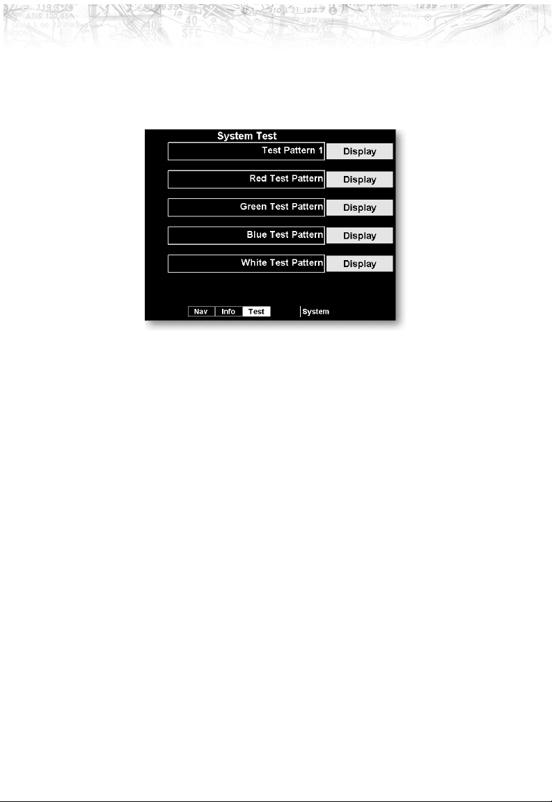
Detailed Operation
System Test Page
The System Test Page allows you to test the display of the
MX20 to ensure proper operation.
62
Page 73
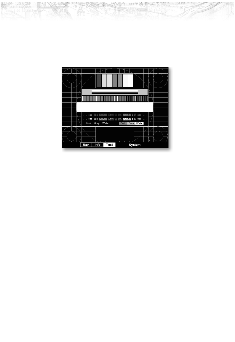
Detailed Operation
Test Pattern 1
The Test Pattern option displays a number of patterns
and colors to test the MX20 display. Use this option to
verify proper operation of the display or when contacting
Customer Service.
Red, Green, Blue, White Test Pattern
Choosing the Red, Green, Blue, or White options floods
the screen with the selected color. Use this option to verify
proper operation of the display or when contacting UPS
Aviation Technologies Customer Service.
63
Page 74

Detailed Operation
Caring For Your MX20
Display Care and Cleaning
Your MX20 has a durable display, but reasonable care
must be taken to maintain its performance and life. To
remove stains, smudges, fingerprints, and so forth, we
recommend these cleaning methods. If the first method
fails to remove the problem, try the next method.
Wipe with a clean, dry, non-abrasive fabric (for
example, cotton or handi-wipes). Do NOT use paper
products, such as paper towels or facial tissues.
Blow on the area to condense moisture on the display
and then wipe the area with the clean fabric.
Moisten a clean fabric with a small amount of water
and wipe the display area.
Apply a small amount of glass cleaner (without
ammonia) to the fabric and wipe the area.
Apply a small amount of isopropyl alcohol and wipe
the area (this is your last resort).
Contacting the Factory
The UPS Aviation Technologies factory may be called
weekdays from 8:00 am until 5:00 pm Pacific time. The
technical service staff will gladly assist you.
UPS Aviation Technologies
Technical Service Department
2345 Turner Rd., SE
Salem, OR 97302 USA
USA Toll Free 800.525.6726
Canada Toll Free 800.654.3415
FAX 503.364.2138
International 503.391.3411
64
Page 75

Troubleshooting
This section contains information to troubleshoot the
MX20 when improper operation is observed. The
following table lists possible problems you could
encounter. Examine the possible causes of the problem
and take the action listed to correct the problem. If you
cannot correct the problem, contact your dealer. If your
dealer is unavailable, contact the UPS Aviation
Technologies factory at the address and phone number
listed in the preceding section. Be sure to have the
information from the System Info page (see page 61) and
the data card available before you contact your dealer or
the factory.
Problem Possible Cause Action
Unit does not power
on or blank screen
Wiring problem
Check for proper
wiring or. Check the
fuse/circuit breaker
Detailed Operation
Unit fails during start
up test
Improper brightness
setting
Low temperature
Data card
Data card
System failure
Check the display
brightness setting
Allow the MX20 to
heat up for approx.
60 seconds
Make sure the data
card is fully inserted
Make sure the data
card is fully inserted
Contact your dealer
or the factory
65
Page 76

Detailed Operation
Problem Possible Cause Action
POS data flag shows Antenna or wiring
Check the antenna
and wiring
Position source wpt
Ensure that a
waypoint is selected
as the current
destination and a Nav
flag is not shown
Position source serial
data
Ensure that the serial
data output is
configured properly
Interference
Have dealer/installer
check for any
interference sources
Installation setup
Have dealer/installer
check for proper
MX20 setup
RTE (Route) flag Position source route Ensure that the
external position
source has an active
route engaged
ALT (Altitude) flag Serial altitude source Ensure the serial
altitude encoder is
powered up and
working properly
Have dealer/installer
check for proper
installation and setup
of the encoder
If altitude data is
provided by an Apollo
GX product, ensure
that the GPS position
has been acquired
and a waypoint is
selected as the
current destination
66
Page 77

Detailed Operation
Problem Possible Cause Action
LT (Lightning) flag WX500 installation Have dealer/installer
check for proper
installation of the
WX500
TER (Terrain) flag Terrain database
Ensure that the
proper database is
used for your location
and it passed the
startup test
Altitude source
No traffic display ADS-B system
installation
“Special Terrain”
message
Capstone/General
Aviation setup
See the Installation Manual for additional troubleshooting
procedures.
Have dealer/installer
check for proper
altitude input
You must have the
ADS-B system
installed
If you do have an
ADS-B system, check
the antennas and
other components for
proper operation
Have dealer/installer
check for proper
MX20 setup
This is normal for the
Capstone installation
Have dealer/installer
check for proper
MX20 setup
67
Page 78

Detailed Operation
Notes
68
Page 79

Index
A
Absolute ...........23
ADS-B .......7-8,11,67
Advisory flags .........7
Aircraft symbol ........59
Airports ........19,24,45
Airspace............28
ALT ..............8
Altitude .........41-42
Annunciations .........7
Arc ..............40
B
Back course..........27
Baro keys ...........47
Barometer ..........49
Barometric correction . . 11, 60
Basic operation ........9
Boundary ...........29
Brightness ...........3,
10
C
Cell ..............56
Contacting the factory ....64
Controls ............3
D
Data card..........5,65
Data flags ...........8
Data port status .......61
Database version .......61
Demo .............57
Desired track up . . . 22, 33, 36
Display ............41
Care ............64
Graphic ..........41
Text ............41
Display Lat/Lon lines ....60
E
Enter key............4
F
Flight ID
Editing ...........44
Flight plan .....8,21,35,45
Function key .........11
Function keys .........3
Functions ...........1
G
Getting started ......1-14
H
Heater .............9
High airways .......29,34
I
IFR..............32
ILS............24,26
Info ..............19
Intersection ..........27
Invert ...........33,36
L
Label ...........34,36
Lat/Lon format........59
Lat/Lon lines .........60
License agreement ......ii
Lightning .....7,31,55-56
Line selection key .......4
Localizer .........24,26
Low airways .......28,34
69
Page 80

LT...............8
M
Map..............17
Info.............19
Orientation ....21,32,35
Pan.............18
Scale ............17
Menu key ...........4
Messages ..........8,16
N
NDB.............27
Noise monitor ........57
North up .......21,33,35
O
OBS..............26
Options ............13
Ownship symbol ...8,37,59
P
Pan..............18
Photosensor ..........3
POS ..............8
Power ............3,9
Pre-Heat ............9
Pressure altitude .....37,42
R
Range ring ..........40
Relative ............23
Relative altitude .....37,42
Roads .............29
Route ..............8
RTE ..............8
S
Self-Test ...........57
SL30 .............24
Software version .......61
Start Up............10
Stormscope ......2,55-57
Strike .............56
Strike test ...........58
Strikes.............31
System ............59
Data ............56
Info.............61
Test ............62
T
TER ............8,49
Terrain .............
2,7-8,11,21-23,46-49,67
Test pattern..........63
Time .............42
Track up .......21,33,35
Track up 360 .....21,33,36
Track up arc .....21,33,35
TRAF .............8
Traffic .........7,30,37
Troubleshooting .......65
V
VFR..............35
VOR..............24
W
Waters ............29
WX500 ......7,31,55-56
Set baro ............60
70
Page 81

Page 82

© 2000 by UPS Aviation Technologies, Inc.
2345 Turner Rd., S.E.
Salem, OR 97302 U.S.A.
Phone 503.581.8101
800.525.6726
In Canada 800.654.3415
FAX 503.364.2138
http://www.upsat.com
Part #560-1026-01
August 2000
 Loading...