

Page 1

36
060588-025
06-02
FOR MORE INFORMATION
USA Local Distributor:
TEL: 1 800-926-5438 or 1 559-662-3900
FAX: 1 559-673-6184
PARTS FAX: 1 559-662-4785
801 S. Pine St., Madera, CA 93637
http://www.upright.com
Europe
TEL: +353-1-620-9300
FAX: +353-1-620-9301
Unit S1, Park West Industrial Park
Friel Avenue, Nangor Road, Dublin 12, Ireland
Pour de plus amples informations
E.U.A. Distributeur local:
Téléphone : 1 800-926-5438 or 1 559-662-3900
Télécopie : 1 559-673-6184
TÉLÉCOPIEUR (PIÈCES): 1 559-662-4785
801 S. Pine St., Madera, CA 93637
http://www.upright.com
Europe
Téléphone : +353-1-620-9300
Télécopie : +353-1-620-9301
Unit S1, Park West Industrial Park
Friel Avenue, Nangor Road, Dublin 12, Ireland
Für weitere Informationen
USA Inr Ortsvertrieb:
TEL: 1 800-926-5438 or 1 559-662-3900
FAX: 1 559-673-6184
Fax für Ersatzteile: 1 559-662-4785
801 S. Pine St., Madera, CA 93637
http://www.upright.com
Europa
TEL: +353-1-620-9300
FAX: +353-1-620-9301
Unit S1, Park West Industrial Park
Friel Avenue, Nangor Road, Dublin 12, Ireland
Para mayor información
USA Distribudor Local:
TÉLÉFONO: 1 800-926-5438 or 1 559-662-3900
FACSÍMIL: 1 559-673-6184
Facsímil para repuestos: 1 559-662-4785
801 S. Pine St., Madera, CA 93637
http://www.upright.com
Europa
TÉLÉFONO: +353-1-620-9300
FACSÍMIL: +353-1-620-9301
Unit S1, Park West Industrial Park
Friel Avenue, Nangor Road, Dublin 12, Ireland
1
SL26/30SL
SL26/30SL
SERIAL NO. 11200 to Current
Operator Manual
Manuel de l’utilisateur
Betriebsanleitung
Manual del operador
AVERTISSEMENT
Tout le personnel doit lire attentivement et respecter toutes les consignes de
sécurité avant d’entretenir ou d’utiliser une plate-forme de travail aérien UpRight.
Réferez-vous à la page 10 pour la version en français de ce manuel de l’utilisateur.
WARNING
All personnel shall carefully read, understand and follow all safety rules, and
operating instructions before performing maintenance on or operating any
UpRight aerial work platform.
Refer to page 2 for the english language version of this Operator Manual.
WARNUNG
Alle Bediener müssen die Sicherheitsregelungen und die Betriebsanweisungen
gründlich durchlesen, verstehen und befolgen, bevor sie Wartungsarbeiten an
irgendeiner UpRight Scheren-Hubbühne vornehmen oder selbige benutzen.
Siehe Seite 18 zwecks der deutschsprachigen Ausgabe dieser Betriebsanleitung.
ADVERTENCIA
Todo el personal debe leer atentamente, entender y respetar todas las reglas de seguridad
y las instrucciones de operación antes de efectuar trabajos de mantenimiento o
manejar cualquier plataforma aérea de trabajo UpRight.
Referirse a la página 26 para la versión en español de este manual del operador.
Page 2

2
SAFETY RULES
NEVER operate the machine
within ten feet of power lines.
THIS MACHINE IS NOT INSULATED.
NEVER elevate or drive
elevated on uneven slopes or
soft ground or elevate the platform unless the platform is level.
NEVER sit, stand or climb on
guardrail or midrail.
NEVER operate the machine without first surveying the work area for surface hazards such as
holes, drop-offs, bumps and debris before operating machine.
NEVER operate the machine if all guardrails are not properly in place and secured with all
fasteners properly torqued.
SECURE gate across entrance after mounting platform.
NEVER use ladders or scaffolding on the platform.
NEVER attach overhanging loads or increase platform size.
LOOK up, down and around for overhead obstructions and electrical conductors.
DISTRIBUTE all loads evenly on the platform. See the back cover for maximum platform load.
NEVER use damaged equipment. (Contact UpRight for instructions, see phone numbers on back cover.)
NEVER change operating or safety systems.
INSPECT the machine thoroughly for cracked welds, loose hardware, hydraulic leaks, damaged
control cable, loose wire connections and wheel bolts.
NEVER climb down elevating assembly with the platform elevated.
NEVER perform service on machine while platform is elevated without blocking elevating assembly.
NEVER recharge batteries near sparks or open flame; batteries that are being charged emit
highly explosive hydrogen gas.
AFTER USE secure the work platform against unauthorized use by turning key switch off and
removing key.
NEVER replace any component or part with anything other than original UpRight replacement
parts without the manufacturer's consent.
English Language Section
35
Notes:
Page 3

34
Notes:
3
Introduction
This manual covers SL26/30 Speed Level Work
Platforms. This manual must be stored on the
machine at all times.
Pre-Operation and Safety
Inspection
Read, understand and follow all safety rules
and operating instructions and then perform the
following steps each day before use.
1. Remove module covers and inspect for damage, oil leaks or missing parts.
2. Check the level of the hydraulic oil with the
platform fully lowered. Oil should be visible in
the sight gauge. Add hydraulic oil, if necessary
(see Specifications, back cover).
3. Check that the fluid level in the battery is
correct (see Battery Maintenance, page 7).
4. Carefully inspect the entire work platform for
damage such as cracked welds or structural
members, loose or missing parts, oil leaks,
damaged cables or hoses, loose connections
and tyre damage.
5. Check that all guardrails are securely in place
with all fasteners properly torqued.
6. Pull Chassis Emergency Stop Button out to ON
position.
Engine inspection
1. Check fuel supply.
2. Check engine oil level with dipstick.
3. While the engine is cool check the radiator
coolant level. DO NOT check coolant when the
engine or radiator is hot.
System Function Inspection
STAND CLEAR of the work platform while
performing the following checks.
Before operating the work platform survey
the work area for surface hazards such as
holes, drop-offs, bumps and debris.
Check in ALL directions, including above
the work platform, for obstructions and
electrical conductors.
Protect control console cable from possible
damage while performing checks.
1. Unhook Controller from front guardrail. Firmly
grasp Controller hanger in such a manner that the
Interlock Lever can be depressed, while performing the following checks from the ground.
2. Pull Controller Emergency Stop Button out to
ON position.
3. Turn Controller Key Switch fully clockwise to
start the engine, releasing the key once the
engine starts.
Note: On Diesel Models, if the engine is cold,
depress and hold the glow plug button for 6
seconds prior to starting to engage the glow
plugs.
4. Place Drive/Level/Lift Switch in DRIVE position.
5. With the Speed Range Switch first in HIGH
TORQUE and then in HIGH SPEED actuate the
Interlock Lever and slowly push the Control
Lever to FORWARD then REVERSE positions
to check for speed and directional control. The
farther you push or pull the Control Lever from
center the faster the machine will travel.
6. Push Steering Switch RIGHT then LEFT to
check for steering control.
7. Place Drive/Level/Lift Switch to LEVEL. While
depressing Interlock Lever actuate the Fore/Aft
and Side/Side Switches to verify they function
properly. Use the Side/Side Switch and tilt the
platform to one side.
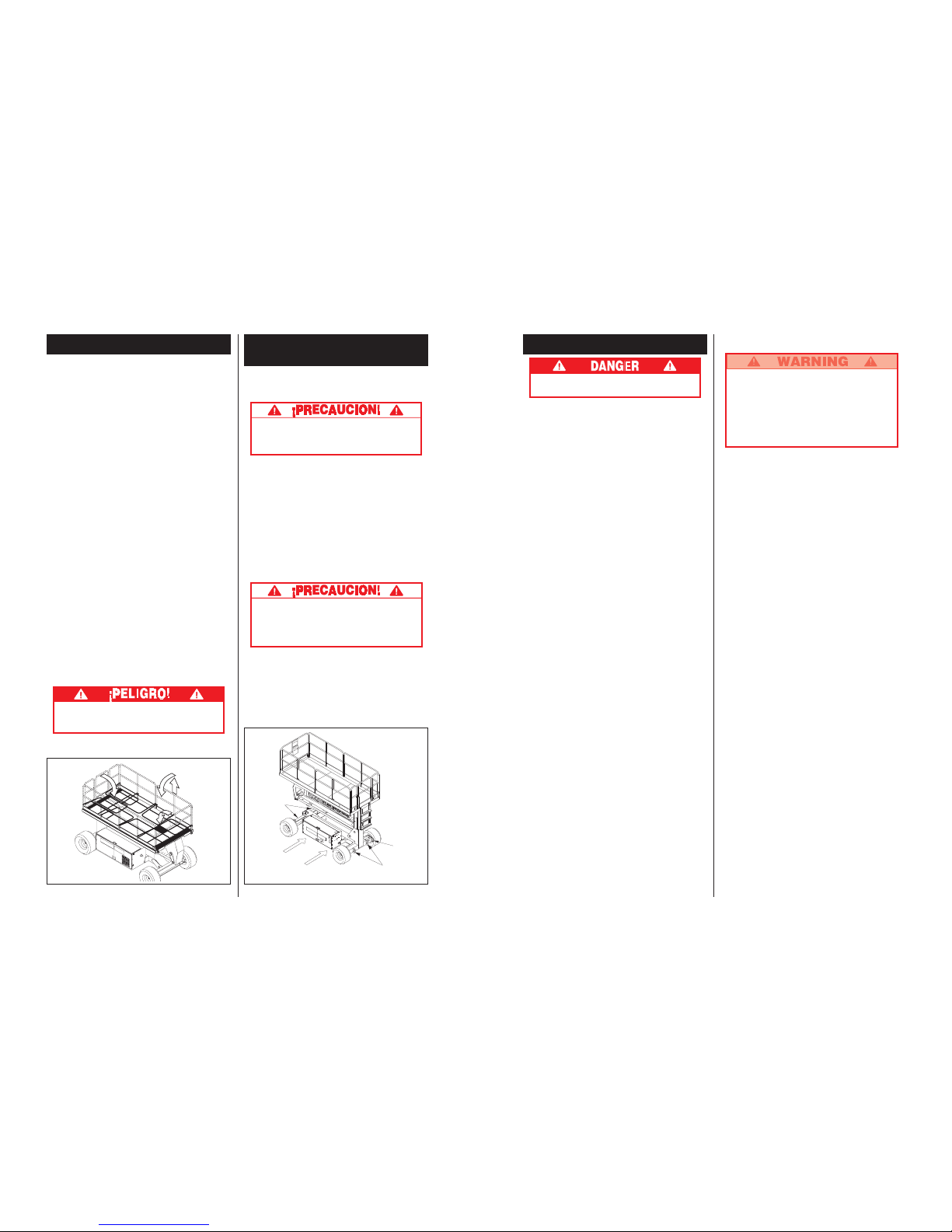
Figure 1: Control Module, Chassis Left Side
Hydraulic Tank
Sight Gauge
Chassis
Emergency
Stop Switch
Emergency
Lowering Valve
Chassis Lift
Switch
Page 4

4
8. Rehook Controller on front guardrail.
9. Push Chassis Lift Switch to UP position and
elevate platform. The platform should only elevate
to the interlock height, about 2.44 m (8 ft.) above
the ground, and the Tilt Alarm should sound. If the
platform continues to elevate and/or there is no
alarm STOP and remove the machine from
service until repaired.
10. Lower the platform with the Chassis Lift Switch.
11. Enter the platform. Using the bubble level as a
guide level the platform with the Side/Side and
Fore/Aft Switches. Dismount platform.
12. Fully elevate platform using Chassis Lift
Switch.
13. Visually inspect the elevating assembly, lift
cylinder, cables and hoses for damage or erratic
operation. Check for missing or loose parts.
14. Lower the platform partially by pushing Chassis
Lift Switch to DOWN, and check operation of
the audible lowering alarm.
15. Push down on the Chassis Emergency Lowering Switch to check for proper operation. Once
the platform is fully lowered, release the switch.
16. Push the Chassis Emergency Stop Button.
17. With only one Emergency Stop Button pushed
down, in the OFF position, operate a control to
verify that the Emergency Stop Switch is
functioning. Repeat the test with only the other
Emergency Stop Switch Button OFF. If any
function operates with either Emergency Stop
Switch in the OFF position STOP and remove
the machine from service until it is repaired.
18. Close and secure module covers.
19. Turn the Controller Key Switch counterclockwise to OFF.
Operation
Before operating work platform, ensure that the
pre-operation and safety inspection has been
completed, any deficiencies have been corrected
and the operator has been thoroughly trained on
this machine.
Travel With Platform Lowered
1. Verify Chassis Emergency Stop Switch is in the
ON position, pull the button out.
2. After mounting platform, close and latch gate.
Check that guardrails are in position and
properly assembled with fasteners properly
torqued.
3. Check that route is clear of persons, obstructions, holes and drop-offs and is capable of
supporting the wheel loads.
4. Check clearances above, below and to the
sides of the platform.
5. Pull Controller Emergency Stop Button out to
ON position.
6. Turn Controller Key Switch fully clockwise to
start the engine, releasing the key once the
engine starts.
Note: On Diesel Models, if the engine is cold,
depress and hold the glow plug button for 6
seconds prior to starting to engage the glow
plugs.
7. Set the Drive/Lift Speed Range Switch to HIGH
TORQUE.
8. Grasp the Control Lever so the Interlock Lever
is depressed (releasing the Interlock Lever cuts
power to Controller). Slowly push or pull the
Control Lever to FORWARD or REVERSE to
travel in the desired direction. The farther you
push or pull the Control Lever from center the
faster the machine will travel.
9. While moving, push the Drive/Lift Speed Range
Switch to HIGH SPEED for travel on level
surfaces or to HIGH TORQUE for climbing
grades or traveling in confined areas.
Steering
Push the Steering Switch RIGHT or LEFT to turn
the wheels. Observe the tyres while maneuvering
to insure proper direction.
Note: Steering is not self-centering. Wheels
must be returned to the straight ahead position
by operating the Steering Switch.
Figure 2: Controller
Interlock
Lever
Steering
Switch
Drive/Lift
Switch
Control Lever
Speed Range
Switch
Key Switch
Glow Plug
Button
Emergency
Stop Switch
33
ARTICULO
Tamaño plataforma (dentro de
rodapié)
Estándar
con extensión
Capacidad máx. plataforma
Estándar
Con extensión
En extensión
No. máx. de ocupantes
Estándar
En extensión
Altura
Trabajo
Máx. plataforma
Mín. plataforma
Dimensiones
Peso
Ancho total
Altura total
Largo total
Altura conducible
Velocidad terrestre
Plataforma baja
Plataforma elevada
Voltaje del sistema
Capacidad del tanque
hidráulico
Presión máx. del sistema
hidráulico
Fluido hidráulico
Uso normal [>32 °F (0 °C)]
Uso con Temp. baja
[-10 a 32 °F (-23 a 0 °C)]
Sistema de elevación
Velocidad de elevación
Nivelado de plataforma
Fuente de energía
Control de conducción
Sistema de control
Conducción horizontal
Neumáticos
Frenos de estacionamiento
Radio de viraje (interno)
Trepabilidad máxima
Distancia entre ejes
Barandillas
Rodapié
SL26SL
1,71 m x 3,59m[67,5 in. x 141,5 in.]
1,71 m x 4,61 m [67,5 in. x 181,5 in.]
680kg [1500 libras]
680kg [1500 libras]
227 kg [500 libras]
5 personas
2 personas
9,75 m [32 pies]
7,93 m [26 pies]
1,5 m [59 pies]
3.075 kg [6.780 libras]
2,13 m [84 pulg.]
2,60 m [102.5 pulg.]
3,79 m [149 pulg.]
7,93 m [26 pies]
0 a 5,0 km/h [0 a 3,1 mph]
0 a 0,8 km/h [0 a 0,5 mph]
12 Voltios CC
45,5 L [12 gal.]
172 bar [2500 psi]
ISO #46
5W-20 Motor Oil
Un cilindro elevación una etapa
Elevación 21 seg./Descenso, 32 seg.
13° lado/lado, 9° anterior/ posterior
Motor Kubota diesel 20 hp 3 cilindros enfriado a agua
Proporcional
Controlador joystick con palanca de enclavamiento y
dirección de cambio con pulgar, interruptores selector de
palanquita y de parada de emergencia; control de
nivelación, dos interruptores de palanca y nivel de
burbuja (inhabilitado para funcionar sobre la altura de
enclavamiento)
Motores hidráulicos, cuatro ruedas
Super Terra-grip, 26 x 12.00-12 NHS,
rellenos con espuma.
Dos, aplicación por resorte, desconexión
hidráulica, discos múltiples.
3,96 m [13 ft.]
19° [35%]
2,54 m [100 in.]
1,11 m [43,5 in.] altura, plegable con puerta
152 mm [6 in.] altura
SL30SL
1,71 m x 4.22 m[67,5in. x 166,25 in.]
N/A
590 kg [1300 libras]
N/D
N/D
5 personas
N/D
10,97 m [36 pies]
9,14 m [30 pies]
1,5 m [59 pies]
3.216 kg [7.090 libras]
2,13 m [84 pulg.]
2,60 m [102.5pulg.]
4,39 m [173 pulg.]
7,93 m [26 pies]
0 a 5,0 km/h [0 a 3,1 mph]
0 a 0,8 km/h [0 a 0,5 mph]
12 Voltios CC
45,5 L [12 gal.]
172 bar [2500 psi]
ISO #46
5W-20 Motor Oil
Un cilindro elevación una etapa
Elevación 24 seg./Descenso, 35 seg.
13° lado/lado, 9° anterior/ posterior
Motor Kubota diesel 20 hp 3 cilindros enfriado a agua
Proporcional
Controlador joystick con palanca de enclavamiento y
dirección de cambio con pulgar, interruptores selector de
palanquita y de parada de emergencia; control de
nivelación, dos interruptores de palanca y nivel de
burbuja (inhabilitado para funcionar sobre la altura de
enclavamiento)
Motores hidráulicos, cuatro ruedas
Super Terra-grip, 26 x 12.00-12 NHS,
rellenos con espuma.
Dos, aplicación por resorte, desconexión
hidráulica, discos múltiples.
3,96 m [13 ft.]
19° [35%]
2,54 m [100 in.]
1,11 m [43,5 in.] altura, plegable con puerta
152 mm [6 in.] altura
*Especificaciones sujetas a cambios sin previo aviso.
Para obtener la información completa sobre piezas y servicio, consultar el Manual de Servicio.
Especificaciones*
Page 5

32
Mantenimiento Periódico
Usar la tabla siguiente como guía para el mantenimiento
periódico. La inspección y el mantenimiento deberán
ser llevados a cabo por el personal entrenado y que
esté familiarizado con los procedimientos
mecánicos y eléctricos. Tomar como referencia el
manual de servicio para estudiar las instrucciones
completas.
Sírvase copiar esta página y usar la tabla de servicio
periódico como lista de trabajos realizados cuando se
inspeccione una máquina para hacerle el mantenimiento.
COMPON. INSPECCION O SERVICIOS INTERVALO S N R
Aceite del Inspeccionar nivel y condición A diario
motor Inspeccionar las fugas A diario
Cambiar filtro de aceite 100 HORAS
Sistema de Inspeccionar nivel de combustible A diario
combus- Inspeccionar las fugas A diario
tible del RReemplazar filtro de combustible 6 M
motor Inspeccionar filtro de aire A diario
Sistema de
Inspeccionar nivel de electrólito A diario
batería del
Inspeccionar gravedad específica 30 D
motor
Limpiar exterior 6 M
Inspeccionar condición del cable de batería A diario
Limpiar bornes 6 M
Líquido
Revisar el nivel de refrigerante (con el motor frío) A diario
refrigerante
Reemplazar el refrigerante 3 M
del motor
Aceite Inspeccionar nivel de aceite A diario
hidráulico Cambiar filtro 6 M
Drenar y reemplazar el aceite 2 A
Sistema Inspeccionar las fugas A diario
hidráulico Inspeccionar conexiones de manguera 30 D
Inspeccionar desgaste exterior de mangueras
30 D
Sistema Abrir la válvula de A diario
hidráulico de descenso y verificar
emergencia el servicio
Controlador Inspeccionar la operación del interruptor A diario
Cable de Inspeccionar pellizcones, dobladuras A diario
control y desgaste exterior del cable
Piso y rieles Inspeccionar el apriete de los tornillos A diario
de la Inspeccionar las grietas de las soldaduras A diario
plataforma Inspeccionar la condición del piso A diario
Neumáticos Inspeccionar los daños A diario
Inspeccionar apriete de, 30
D
tuercas/pernos a 123 Nm (90 pies/lb)
Bomba Limpiar correctamente 30 D
hidráulica Inspeccionar fugas en superficies encaradas 30 D
Inspeccionar fugas en mangueras conectoras
A diario
Inspeccionar el apriete correcto de los pernos 30
D
de montaje
Inspeccionar el apriete y la alineación 1 A
Motores de Inspeccionar operación y fugas A diario
conducción
Sistema Inspeccionar el apriete correcto 6
M
de dirección de herrajes y conexiones 30 D
Aceitar los pernos maestros 30 D
Inspeccionar las fugas del cilindro de dirección 30 D
y el apriete correcto de los pernos de montaje
Ensamblaje Inspeccionar grietas estructurales A diario
de elevación Inspeccionar desgaste de puntos pivotales 30 D
Inspeccionar apriete correcto de pernos 30 D
pivotales de clavijas de montaje
Inspec. desgaste de engranaje de conexión 6 M
Inspec. dobladuras de brazos de elevación 6 M
Engrasar clavijas de conexión 30 D
Engrasar engranajes de conexión 30 D
Clave de la tabla para servicio periódico
Intervalo
A diario=cada turno (cada día) o cada ocho horas
30d=cada mes (30 días) ó cada 50 horas
3m=cada 3 meses ó 125 horas
6m=cada 6 meses ó 250 horas
1a=cada año ó 500 horas
2a=cada 2 años ó 1000 horas
S=Sí/Aceptable
N=No/No aceptable
R=Reparado/Aceptable
COMPON. INSPECCION O SERVICIOS INTERVALO S N R
Chasis Inspeccionar pellizcones o puntos de roce A diario
de las mangueras
Inspeccionar el apriete correcto del 6
M
montaje del componente
Inspeccionar grietas de soldaduras A diario
Cilindro de Inspec. el desgaste de la varilla de cilindro 30 D
elevación Inspeccionar el apriete correcto de los 30 D
pernos pivotales de las clavijas de montaje
Inspec. anillos presión de clavijas pivotales 30 D
Inspeccionar fugas de los sellos 30 D
Inspeccionar desgaste de puntos pivotales 30 D
Inspeccionar apriete correcto de conexiones 30 D
Cilindro de Inspeccionar el desgaste de la varilla de cilindro 30 D
acción Inspeccionar el apriete correcto de los pernos 30 D
anterior/ pivotales de las clavijas de montaje
posterior Inspeccionar fugas de los sellos 30 D
Inspeccionar desgaste de puntos pivotales 30 D
Inspeccionar apriete correcto de conexiones 30 D
Cilindro de Inspeccionar el desgaste de la varilla de cilindro 30 D
lado/lado Inspeccionar el apriete correcto de los pernos 30 D
pivotales de las clavijas de montaje
Inspeccionar fugas de los sellos 30 D
Inspeccionar desgaste de puntos pivotales 30 D
Inspeccionar apriete correcto de conexiones 30 D
Cilindro Inspeccionar el desgaste de la varilla de cilindro 30 D
del eje Inspeccionar el apriete correcto de los pernos 30 D
pivotales de las clavijas de montaje
Inspeccionar fugas de los sellos 30 D
Inspeccionar desgaste de puntos pivotales 30 D
Inspeccionar apriete correcto de conexiones 30 D
Nivel de Inspeccionar los daños del anillo de objetivo A diario
burbuja y las piezas de la burbuja
Unidad Inspeccionar y reparar daños A diario
completa de colisión
Inspeccionar apriete correcto de los tornillos 3 M
Inspeccionar corrosión - sacar y 6 M
pintar nuevamente
Lubricar 30 D
Rótulos Inspeccionar rótulos - reemplazar los A diario
deteriorados, faltantes o ilegibles
Informe de servicio
Fecha:_______________
Propietario: ___________
No. de Modelo: ________ No. de Serie: ______
Servicio realizado por: ____________________
Intervalo de Servicio: _____________________
5
Levelling Platform
With Drive/Level/Lift Switch in LEVEL hold the
Control Lever so the Interlock Lever is depressed.
Center bubble in bubble level using Fore/Aft and
Left/Right Switches. To level the platform forward it
may be necessary to elevate the platform slightly.
Raising and Lowering The Platform
1. Position the Drive/Level/Lift Switch to LIFT.
2. While holding the Control Lever so the Interlock
Lever is depressed, push the Control Lever
slowly to UP to raise the platform. Pushing the
Control Lever farther increases the lift speed. If
the platform does not elevate above the interlock height, about 2.44 m (8 ft.), fully lower
platform and re-level.
3. When the work task is completed, position the
Drive/Level/Lift Switch to LIFT and lower the
platform by pulling back on the Control Lever
until the platform is fully lowered.
Travel With Work Platform Elevated
Travel with platform elevated ONLY on firm flat
surfaces.
Note: The Work Platform will travel at reduced
speed when in the elevated position. SL30
Models will only drive while elevated when the
Platform is below 8m (26 ft.) in height.
1. Check that the route is clear of persons, obstructions, holes and drop-offs, is level and
capable of supporting the wheel loads.
2. Check clearances above, below and to the
sides of platform.
3. Position the Drive/Level/Lift Switch to the
DRIVE position.
4. Push the Control Lever to FORWARD or
REVERSE for the desired direction of travel.
If the machine quits driving and the Tilt Alarm
sounds, immediately lower and re-level the
platform before attempting to elevate again.
Emergency Lowering
The Emergency Lowering Switch is located on
the left hand side of the chassis through the
cutout in the Control Module cover.
1. Open the Emergency Lowering Valve by
pushing down on the Emergency Lowering
Switch.
2. Once the platform is fully lowered, release the
switch to close the Emergency Lowering Valve.
The platform will not elevate if the Emergency
Lowering Valve has not been closed.
After Use Each Day
1. Ensure that the platform is fully lowered.
2. Park the machine on level ground, preferably
under cover, secure against vandals, children
or unauthorized operation.
3. Turn the Key Switch to OFF and remove the
key to prevent unauthorized operation.
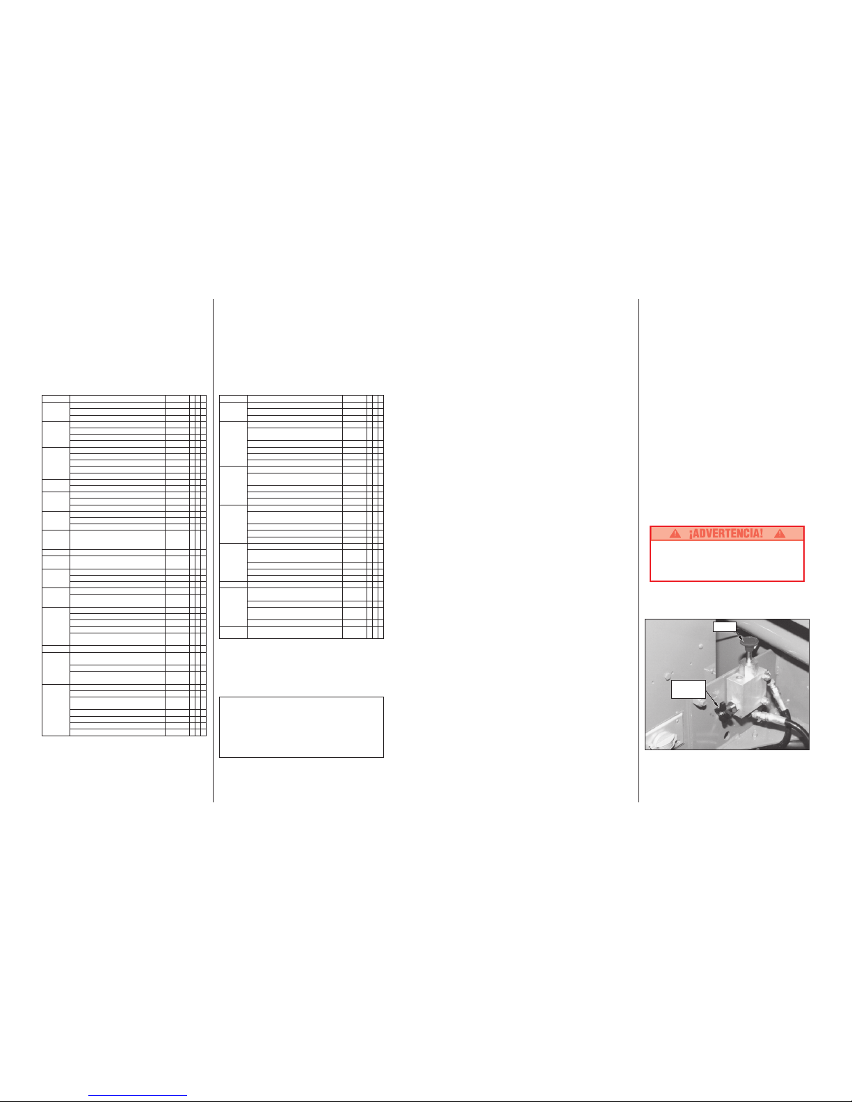
Parking Brake Release (Figure 3)
Perform the following only when the machine will
not operate under its own power and it is necessary to move the machine or when towing the
machine up a grade or wenching onto a trailer to
transport.
1. Close the needle valve by turning the knob
clockwise.
2. Pump the Brake Release Pump until the Parking
Brakes release and the wheels can be turned.
3. The machine will now roll when pushed or
pulled.
4. Be sure to open the needle valve and verify
that the Parking Brakes have engaged before
the machine is operated.
Never operate work platform with the
Parking Brakes inoperative. Serious injury
or damage could result.
Never tow faster than .3 m/sec. (1 ft./sec.).
Pump
Needle Valve
Figure 3: Brake Release Pump
Page 6

6
Fold Down Guardrails
This procedure is only for passing through doorways. Guardrails must be returned to proper
position before using the machine.
Fold Down Procedure (Figure 4)
Note: When performing the following procedures retain all fasteners.
1. Place controller on platform.
2. Starting at the front of the platform, remove
nuts, bolts and washers from the top of the
front guardrail. Fold the front guardrail down
onto the platform.
3. Close and latch the gate.
4. Remove nuts, bolts and washers from the top
of the rear guardrail. Fold the rear guardrail
down onto the platform being careful to keep
gate latched at all times.
5. Remove nuts, bolts and washers from the top
of the side guardrails and from the slideout
deck midrail. Lift up and fold one side guardrail
in so it rests on the deck. Repeat with other
side guardrails.
Erection Procedure
1. Raise side guardrails making sure each is
pushed down to secure the guardrail in the
vertical position.
2. Install bolts, washers and nuts between the
side guardrails, tighten securely.
3. Raise rear guardrail assembly, aligning holes
and install bolts, washers and nuts. Tighten
securely.
4. Raise front guardrail, aligning holes and install
bolts, washers and nuts. Tighten securely.
5. Hang controller from front guardrail.
6. Before operating work platform check that all
fasteners are in place and properly torqued.
Before entering Platform, guardrails must
be securely fastened in their proper position.
Transporting Work Platform
By Forklift
Note: Forklifting is for transporting only.
See specifications for weight of work platform
and be certain that forklift is of adequate
capacity to lift platform.
Forklift from side of Chassis by lifting under the
Chassis Modules (Figure 5).
By Crane
1. Secure straps to Chassis Lifting Lugs only
(Figure 5).
By Truck
1. Manoeuvre the work platform into transport
position and chock wheels.
2. Secure the work platform to the transport
vehicle with chains or straps of adequate load
capacity attached to the chassis tie down lugs
(Figure 5).
Tie down lugs are not to be used to lift work
platform.
Overtightening of chains or straps through
tie down lugs may result in damage to work
platform.
Figure 4: Fold Down Guardrails
Figure 5: Transporting Work Platform
Front Tie
Downs/
Lifting Lugs
Forklift
Rear Lifting
Lug
(Typical)
Rear Tie
Downs
31
Mantenimiento
Nunca efectuar trabajos de mantenimiento en la
plataforma de trabajo mientras ésta esté
elevada.
Nota: En ningún trabajo de mantenimiento normal
(periódico) para el SL26/30N se necesita que la
plataforma tenga que elevarse.
Mantenimiento de baterias
Riesgo de una mezcla de gas explosiva. Mantener
las chispas, llamas y cigarrillos lejos de las
baterías.
Siempre usar gafas protectoras cuando se
trabaje en las baterías.
El fluido de las baterías es muy corrosivo.
Enjuagar bien el fluido derramado con agua
limpia.
Inspección y limpieza de las baterías
Revisar diariamente el nivel de fluido de las baterías,
especialmente si se está usando la plataforma de
trabajo en un clima seco y caluroso. Si el nivel del
electrólito está más bajo que 10 mm (3/8 pulg.) sobre
las placas, añadir agua destilada y limpia solamente. El
uso de agua de la canilla con un alto contenido mineral
acortará la vida útil de la batería.
Inspeccionar la batería regularmente por si la caja está
quebrada, hay fugas de electrólitos y los bornes
presentan corrosión. Verificar que los cables no tengan
el aislamiento gastado o roto y que los conectores de
los bornes no estén averiados.
Limpiar la batería cuando se observe corrosión en los
bornes o cuando el electrólito se haya desbordado
durante la carga. Usar una solución con bicarbonato de
sosa para limpiar la batería, con cuidado para que no
se introduzca en las celdas. Enjuagar completamente
con agua limpia. Siempre que se cambie un cable,
limpiar la superficies de contacto de la batería y el
cable hasta obtener un acabado metálico brillante.
Page 7
30
Barandillas plegables
Este procedimiento es solamente para pasar por los
portales. Las barandillas se deben colocar en su
posición correcta antes de usar la máquina.
Procedimiento para plegarlas (Figura 4)
Nota: Cuando se lleven a cabo los siguientes
procedimientos, se deben guardar todos los tornillos.
1. Coloque el contralor en la plataforma.
2. Empezando por el frente, saque los pernos,
tuercas y arandelas de encima de la baranda
delantera. Abata la baranda delantera sobre la
plataforma.
3. Cierre la puerta con pestillo.
4. Saque los pernos, tuercas y arandelas de encima
de la baranda trasera. Abata la baranda sobre la
plataforma cuidando mantener la puerta con
pestillo todo el tiempo.
5. Saque los pernos, tuercas y arandelas de encima
de las barandas laterales y del eje medio de la
plataforma deslizante. Levante y voltee la baranda
de un lado dejándola sobre la plataforma. Repítalo
con la baranda opuesta.
Procedimiento de Erección
1. Levante las barandas laterales y empújelas hacia
abajo para asegurarlas en la posición vertical.
2. Instale pernos, arandelas y tuercas entre las
barandas laterales y apriételos bien.
3. Levante el ensamble de la baranda trasera, alinee
hoyos e instale pernos, arandelas y tuercas.
4. Levante la baranda delantera, alinee agujeros e
instale pernos, arandelas y tuercas. Apríetelos
bien.
5. Cuelgue el contralor en la baranda delantera.
6. Antes de operar la plataforma de trabajo verifique
que los pernos estén en su lugar y apretados al par
de torsión correcto.
Antes de entrar a la plataforma, las barandillas
deben estar atornilladas seguramente en sus
posiciones apropiadas.
Transporte de la plataforma
de trabajo
Por montacarga
Nota: El montacarga es para transporte solamente.
Ver las especificaciones para el peso de la
plataforma de trabajo y tener la certeza de que
el montacarga es de la capacidad adecuada
para levantar la plataforma.
Levantar con el montacarga desde el costado del
chasis, por debajo de los módulos (Figura 5).
Por grúa
Fijar las correas solamente a las orejetas para izar del
chasis (Figura 5).
Por camión
1. Maniobrar la plataforma de trabajo a la posición de
transporte y bloquear las ruedas.
2. Sujetar la plataforma de trabajo al vehículo de
transporte con cadenas o correas de la capacidad
de carga adecuada sujetas a las orejetas de
amarre del chasis (Figura 5).
No usar las orejetas de amarre para levantar la
plataforma de trabajo.
El apriete excesivo de las cadenas o correas
en las orejetas de amarre puede dañar la
plataforma de trabajo.
Figura 4: Barandillas plegables Figura 5: Transporte de la plataforma de trabajo
Orejeta para
izar (típica)
Orejetas de
amarre traseras
Montacarga
Orejetas de
amarre/
orejetas
para izar
delanteras
7
Maintenance
Never perform service on the work platform
while the platform is elevated.
Note: No normal (routine) maintenance on the
SL26/30SL should require the platform to be
raised.
Battery Maintenance
Hazard of explosive gas mixture. Keep
sparks, flame, and smoking material away
from battery.
Always wear safety glasses when working
with batteries.
Battery fluid is highly corrosive. Thoroughly
rinse away any spilled fluid with clean water.
Battery Inspection and Cleaning
Check battery fluid level daily, especially if work
platform is being used in a warm, dry climate. If the
electrolyte level is lower than 10 mm (
3
/8 in.) above
the plates, add clean, distilled water only. Use of
tap water with high mineral content will shorten
battery life.
The battery should be inspected regularly for signs
of cracks in the case, electrolyte leakage and
corrosion of the terminals. Inspect cables for worn
spots or breaks in the insulation and for broken
cable terminals.
Clean the battery when there is signs of corrosion
at the terminals or when electrolyte has overflowed
during charging. Use a baking soda solution to
clean the battery, taking care not to get the solution
inside the cells. Rinse thoroughly with clean water.
Clean battery and cable contact surfaces to a
bright metal finish whenever a cable is removed.
Page 8
8
Routine Service
Use the following table as a guide for routine
maintenance. Inspection and maintenance shall
be performed by personnel who are trained and
familiar with mechanical and electrical procedures. Refer to the Service Manual for complete
service instructions.
Please copy this page and use the Routine Service
Table as a checklist when inspecting a machine for
service.
COMPONENT INSPECTION OR SERVICES INTERVAL Y N R
Engine Oil Check level and condition Daily
Check for leaks Daily
Change oil & filter 100 HOURS
Engine Fuel Check fuel level Daily
System Check for leaks Daily
Replace fuel filter 6M
Check air cleaner Daily
Engine Check electrolyte level Daily
Battery Check specific gravity 30D
System Clean exterior 6M
Check battery cable condition Daily
Clean terminals 6M
Engine Check coolant level (with engine cold) Daily
Coolant Replace coolant 3M
Hydraulic Oil Check oil level Daily
Change filter 6M
Drain and replace oil 2Y
Hydraulic Check for leaks Daily
System Check hose connections 30D
Check hoses for exterior wear 30D
Emergency Open the emergency lowering Daily
Hydraulic valve and check for
System serviceability
Controller Check switch operation Daily
Control Check the exterior of the cable Daily
Cable for pinching, binding or wear
Platform Check fasteners for proper torque Daily
Deck and Check welds for cracks Daily
Rails Check condition of deck Daily
Tyres Check for damage Daily
Check lug nuts/bolts, 30
D
torque to 123 Nm (90 ft. lbs.)
Hydraulic Wipe clean 30D
Pump Check for leaks at mating surfaces 30D
Check for hose fitting leaks Daily
Check mounting bolts for proper torque 30D
Check the drive coupling for proper
alignment and wear 1Y
Drive Motors Check for operation and leaks Daily
Steering Check hardware & fittings for proper torque 6
M
System Grease pivot pins 30D
Oil king pins 30D
Check steering cylinder for leaks & 30D
mounting bolts for proper torque
Elevating Inspect for structural cracks Daily
Assembly Check pivot points for wear 30D
Check mounting pin pivot bolts 30D
for proper torque
Check linkage gear for wear 6M
Check elevating arms for bending 6M
Grease linkage pins 30D
Grease linkage gear 30D
Service Report
Date: ______________
Owner: ________________________________
Model No: ____________ Serial No: _________
Serviced By: ____________________________
Service Interval: _________________________
Routine Service Table Key
Interval
Daily=each shift (every day) or every eight hours
30d=every month (30 days) or every 50 hours
3m=every 3 months or 125 hours
6m=every 6 months or 250 hours
1y=every year or 500 hours
2y=every 2 years or 1000 hours
Y=Yes/Acceptable
N=No/Not Acceptable
R=Repaired/Acceptable
COMPONENT INSPECTION OR SERVICES INTERVAL Y N R
Chassis Check hoses for pinch or rubbing points Daily
Check component mounting for proper torque 6M
Check welds for cracks Daily
Lift Check the cylinder rod for wear 30D
Cylinder Check mounting pin pivot bolts 30D
for proper torque
Check pivot pin snap rings 30D
Check seals for leaks 30D
Inspect pivot points for wear 30D
Check fittings for proper torque 30D
Fore/Aft Check the cylinder rod for wear 30D
Cylinder Check mounting pin pivot bolts 30D
for proper torque
Check seals for leaks 30D
Inspect pivot points for wear 30D
Check fittings for proper torque 30D
Side/Side Check the cylinder rod for wear 30D
Cylinder Check mounting pin pivot bolts 30D
for proper torque
Check seals for leaks 30D
Inspect pivot points for wear 30D
Check fittings for proper torque 30D
Axle Check the cylinder rod for wear 30D
Cylinder Check mounting pin pivot bolts 30D
for proper torque
Check seals for leaks 30D
Inspect pivot points for wear 30D
Check fittings for proper torque 30D
Bubble Level Check bubble and target ring for damage. Daily
Entire Check for and repair Daily
Unit collision damage
Check fasteners for proper torque 3M
Check for corrosion-remove 6M
and repaint
Lubricate 30D
Labels Check for peeling, missing, or unreadable Daily
labels & replace
29
Plataforma de nivelación
Colocar el interruptor de conducción/nivelación/
elevación en NIVELACION (LEVEL) y sujetar la palanca
de control de manera que la palanca de enclavamiento
esté oprimida. Centrar la burbuja del nivel usando los
interruptores de acción anterior/posterior y de izquierda/
derecha. Para nivelar la plataforma hacia adelante podrá
ser necesario elevarla un poco.
Para Elevar y Bajar la Plataforma
1. Poner el interruptor de conducción/elevación en la
posición ELEVACION (LIFT).
2. Mientras se sujeta la palanca de control de tal
manera que la palanca de enclavamiento esté
oprimida, empujar la palanca de control lentamente
hacia ARRIBA (UP) para elevar la plataforma.
Cuanto más se empuja la palanca de control, tanto
más se incrementa la velocidad de elevación. Si la
plataforma no se eleva sobre la altura de
enclavamiento, alrededor de 2,44 m (8 pies), bajarla
totalmente y nivelar nuevamente.
3. Cuando se hayan terminado las tareas, colocar el
interruptor de conducción/nivelación/elevación en
la posición ELEVACION (LIFT) y empujar hacia
atrás la palanca de control para bajar la plataforma
hasta que quede totalmente abajo.
Viaje con la plataforma elevada
Viajar con la plataforma elevada SOLAMENTE sobre
superficies planas y firmes.
Nota: La plataforma de trabajo viajará a velocidad
reducida cuando está elevada. Los Modelos SL30
solamente se podrán conducir con la plataforma
elevada a menos de 8m (26 pies).
1. Ver que la vía esté despejada de personas,
obstáculos, hoyos y declives, que esté nivelada y
que sea capaz de soportar el peso de las ruedas.
2. Verificar el despeje encima, debajo y en los
costados de la plataforma.
3. Colocar el interruptor de conducción/nivelación/
elevación en la posición CONDUCCION (DRIVE).
4. Empujar la palanca de control para ADELANTE
(FORWARD) o para ATRAS (REVERSE), según la
dirección que se desee viajar.
Si la máquina deja de andar y suena la alarma de
inclinación, se debe bajar la plataforma
inmediatamente y nivelar la plataforma nuevamente
antes de tratar de elevarla otra vez.
Descenso de emergencia
El interruptor de descenso de emergencia está
ubicado en el costado de mano izquierda del
chasis, a través de la abertura de la cubierta del
módulo de control.
1. Abrir la válvula de descenso de emergencia
empujando el interruptor de descenso de
emergencia hacia abajo.
2. Soltar el interruptor cuando la plataforma esté
totalmente abajo para cerrar la válvula de
descenso de emergencia. La plataforma no se
elevará si la válvula de descenso de emergencia
no se ha cerrado.
Después del uso diario
1. Asegurarse que la plataforma quede totalmente
abajo.
2. Estacionar la máquina en terreno plano,
preferiblemente bajo techo, protegida contra
vandalismo, niños u operación por personas no
autorizadas.
3. DESCONECTAR (OFF) el interruptor de llave y
sacar la llave para prevenir la operación no
autorizada.
Embrague del freno de
estacionamiento (Figura 3)
Proceder de la manera siguiente solamente cuando la
máquina no funcione accionada por su propio motor y
sea necesario trasladarla, o cuando se remolque la
máquina subiendo una pendiente o subiéndola tirada
por cable a un camión para su transporte.
1. Cerrar la válvula de aguja haciendo girar la perilla
en el sentido de las agujas del reloj.
2. Accionar la bomba de separación hasta que el
freno de estacionamiento se separe y las ruedas
puedan girar.
3. Después, la máquina se podrá hacer rodar al
empujarla o tirar de ella.
4. Asegurarse de abrir la válvula de aguja y verificar
que el freno de estacionamiento haya quedado
engranado antes de hacer funcionar la máquina.
Nunca hacer funcionar la plataforma de trabajo
con los frenos de estacionamiento inoperantes.
Se pueden causar graves lesiones o daños.
Nunca remolcar la máquina a más de 0,3 m/s (1 pie/s).
Bomba
Figura 3: Bomba para soltar los frenos
Válvula de
aguja
Page 9

28
8. Volver a enganchar el controlador en la barandilla
delantera.
9. Empujar el interruptor de elevación del chasis a la
posición ARRIBA (UP) y elevar la plataforma. La
plataforma se deberá elevar solamente hasta la
altura de enclavamiento, alrededor de 2,44 m (8
pies) sobre la tierra y la alarma de inclinación debe
sonar. Si la plataforma continúa elevándose y/o no
suena la alarma, debe PARAR (STOP) y sacar la
máquina de servicio hasta que se la repare.
10. Bajar la plataforma con el interruptor de elevación
del chasis.
11. Subir a la plataforma. Usar el nivel de burbuja como
guía para nivelar la plataforma con los interruptores
de lado/lado y de acción anterior/posterior. Bajar de
la plataforma.
12. Elevar la plataforma totalmente usando el
interruptor de elevación del chasis.
13. Inspeccionar visualmente la plataforma elevadora,
el cilindro de elevación, los cables y las mangueras
para ver si están rotos o funcionan irregularmente.
Buscar si hay piezas sueltas.
14. Bajar parcialmente la plataforma empujando el
interruptor de elevación del chasis hacia ABAJO
(DOWN) e inspeccionar la operación de la alarma
audible de bajada.
15. Empujar hacia abajo del interruptor de bajada de
emergencia del chasis para verificar que la operación
es correcta. Una vez que la plataforma esté
totalmente baja, soltar el interruptor.
16. Empujar el botón de parada de emergencia del chasis.
17. Con solamente el botón de parada de emergencia
empujado hacia abajo, en la posición APAGADO
(OFF), hacer funcionar un control para verificar que
el interruptor de parada de emergencia funciona.
Repetir esa prueba con solamente el otro botón
interruptor de parada de emergencia en APAGADO
(OFF). Si alguna función hace la operación con el
interruptor de parada de emergencia en la posición
de APAGADO (STOP), se debe PARAR y sacar la
máquina de servicio hasta que se la repare.
18. Cerrar y asegurar las cubiertas de los módulos.
19. Girar el interruptor de llave del controlador en el
sentido contrario a las agujas del reloj hasta
APAGADO (OFF).
Operación
Antes de hacer funcionar la plataforma de trabajo,
asegurarse que se haya completado la inspección de
seguridad y previa a la operación, que los problemas
estén solucionados y que el operador esté totalmente
entrenado para usar la máquina.
Viaje con la Plataforma Abajo
1. Verificar que el interruptor de parada de
emergencia del chasis esté en la posición
ENCENDIDO (ON ), tirar del botón hacia afuera.
2. Después de subir a la plataforma y cerrar la puerta
con el pestillo, inspeccionar que las barandillas estén
en sus posiciones y ensambladas apropiadamente
con los tornillos apretados.
3. Ver que la vía esté despejada de personas,
obstáculos, hoyos y declives, que esté plana y que
sea capaz de soportar el peso de las ruedas.
4. Inspeccionar el espacio que existe arriba, abajo y a
los costados de la plataforma.
5. Tirar hacia afuera del botón de parada de emergencia
del controlador hasta la posición ENCENDIDO (ON).
6. Girar el interruptor de llave del controlador en el
sentido de las agujas del reloj para hacer arrancar
el motor, soltarla cuando arranque.
Nota: En los Modelos Diesel, si el motor está frío,
presione y sostenga, durante 6 segundos, el botón
de la bujías de incandescencia para conectarlas.
7. Colocar el interruptor de rango de velocidad para
conducción/elevación en ALTA TORSION (HIGH
TORQUE).
8. Sujetar la planca de control de tal manera que la
palanca de enclavamiento esté oprimida (al soltar la
palanca de enclavamiento se le corta la corriente
eléctrica al controlador). Empujar o tirar lentamente
de la palanca de control hacia ADELANTE (FOR-
WARD) o hacia ATRAS (REVERSE), según la
dirección que se desee viajar. A medida que se
empuja o se tira de la palanca de control, alejándola
del centro, la máquina va a andar más rápido.
9. A medida que se mueva, se debe empujar el
interruptor de rango de velocidad para conducción/
elevación a ALTA VELOCIDAD (HIGH SPEED)
para andar sobre superficies niveladas o cambiarlo
a ALTA TORSION (HIGH TORQUE) para subir
pendientes o viajar en áreas con espacios limitados.
Dirección
Empujar el interruptor de dirección hacia la DERECHA
(RIGHT) o la IZQUIERDA (LEFT) para girar las ruedas.
Observar los neumáticos mientras se maniobra para
asegurarse de que la dirección esté correcta.
Nota: La dirección no se centra por sí sola. Es
necesario reponer las ruedas a la posición recta
hacia adelante accionando el interruptor de
dirección.
Figura 2: Controlador
Interruptor de Llave
Interruptor del
Rango de
Velocidad
Palanca de
Enclavamiento
Interruptor de
Dirección
Palanca de Control
Interruptor de
Conducción/
Elevación
Interruptor de
Parada de
Emergencia
Botón de bujía de
incandescencia
9
Specifications*
* Specifications subject to change without notice.
Refer to Service Manual for complete parts and service information.
ITEM
Platform Size
(Inside Toeboards)
Standard
w/ Extension
Max. Platform Capacity
Standard
w/ Extension
on Extension
Max. No. of occupants
Standard
on Extension
Height
Working Height
Max. Platform Height
Min. Platform Height
Dimensions
Weight
Overall Width
Overall Height
Overall Length
Driveable Height
Surface Speed
Platform Lowered
Platform Raised
System Voltage
Hydraulic Tank Capacity
Maximum Hydraulic System
Pressure
Hydraulic Fluid
Normal Use (>32 °F [0 °C])
Low Temp. Use
(-10 to 32 °F [-23 to 0 °C])
Lift System
Lift Speed
Platform Levelling
Power Source
Drive Control
Control System
Horizontal Drive
Tyres
Parking Brakes
Turning Radius (inside)
Maximum Gradeability
Wheel Base
Guardrails
Toeboard
SL26SL
1.71 m x3.59m[67.5 in. x 141.5 in.]
1.71 m x 4.61 m [67.5 in. x 181.5 in.]
680kg [1500 lbs.]
680kg [1500 lbs.]
227 kg [500 lbs.]
5 people
2 people
9.75 m [32 ft.]
7.93 m [26 ft.]
1.5 m [59 in.]
3,075 kg [6,7800 lbs.]
2.13 m [84 in.]
2.60 m [102.5 in.]
3.79 m [149 in.]
7.93 m [26 ft.]
0 to 5.0 km/h [0 to 3.1 mph]
0 to .8 km/h [0 to .5 mph]
12 Volt DC
45.5 L [12 gal.]
172 bar [2500 psi]
ISO #46
5W-20 Motor Oil
One Single Stage Lift Cylinder
Raise, 21 sec./Lower, 32 sec.
13° Side/Side, 9° Fore/Aft
20 HP Kubota Diesel, 3 Cylinder, Water Cooled Engine
Proportional
Joystick Controller with Interlock Lever and Thumb
Rocker Steering, Selector and Emergency Stop
Switches; Levelling Control, Two Toggle Switches
and Bubble Level (inoperable above interlock height)
Four Wheel, Hydraulic Motors
26 x 12.00 - 12 NHS Super Terra-grip, Foam Filled
Two, Spring Applied, Hydraulic Release, Multiple Disc
3.96 m [13 ft.]
19° [35%]
2.54 m [100 in.]
1.11 m [43.5 in.] high, Fold Down with Gate
152 mm [6 in.] High
SL30SL
1.71 m x 4.22m[67.5 in. x 166.25 in.]
N/A
590 kg [1300 lbs.]
N/A
N/A
5 people
N/A
10.97 m [36 ft.]
9.14 m [30 ft.]
1.5 m [59 in.]
3,216 kg [7,090 lbs.]
2.13 m [84 in.]
2.60 m [102.5 in.]
4.39 m [173 in.]
7.93 m [26 ft.]
0 to 5.0 km/h [0 to 3.1 mph]
0 to .8 km/h [0 to .5 mph]
12 Volt DC
45.5 L [12 gal.]
172 bar [2500 psi]
ISO #46
5W-20 Motor Oil
One Single Stage Lift Cylinder
Raise, 24 sec./Lower, 36 sec.
13° Side/Side, 9° Fore/Aft
20 HP Kubota Diesel, 3 Cylinder, Water Cooled Engine
Proportional
Joystick Controller with Interlock Lever and Thumb
Rocker Steering, Selector and Emergency Stop
Switches; Levelling Control, Two Toggle Switches
and Bubble Level (inoperable above interlock height)
Four Wheel, Hydraulic Motors
26 x 12.00 - 12 NHS Super Terra-grip, Foam Filled
3.96 m [13 ft.]
19° [35%]
2.54 m [100 in.]
1.11 m [43.5 in.] high, Fold Down with Gate
152 mm [6 in.] High
Page 10

10
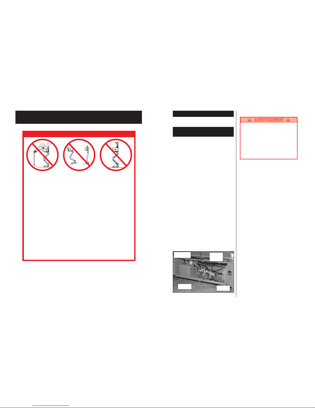
RÈGLES DE SÉCURITÉ
NE JAMAIS UTILISER la
machine à moins de trois
mètres des lignes électriques.
CETTE MACHINE N’EST PAS
ISOLÉE.
NE JAMAIS élever la plate-
forme ou conduire la machine
levée sur une pente accidenté
ou un sol meuble ou élever la
plate-forme à moins que la
machine ne soit sur une surface
ferme et horizontale.
NE JAMAIS s’asseoir, se tenir
debout ou monter sur le
garde-corps.
Version Française
NE JAMAIS utiliser la machine sans avoir au préalable examiné la zone de travail en recherchant les
dangers de surface, comme les trous, les pentes, les bosses et les débris.
NE JAMAIS utiliser la machine si les garde-corps ne sont pas correctement en place et bloqués avec des
vis bien serrées.
REFERMER le portillon après être monté sur la plate-forme.
NE JAMAIS utiliser d’échelles ou d’échafaudages sur la plate-forme.
NE JAMAIS fixer de charge en surplomb ni élargir la plate-forme.
REGARDER en haut, en bas et tout autour en cherchant les fils électriques et les obstacles.
RÉPARTIR les charges sur la plate-forme uniformément. Voir au dos du manuel la charge maximum de la plate-
forme.
NE JAMAIS utiliser d’équipement endommagé (contacter UpRight pour des instructions. Voir le numéro
d’appel gratuit au dos du manuel).
NE JAMAIS changer le système de fonctionnement ou de sécurité.
INSPECTER soigneusement la machine en recherchant les soudures fissurées, la visserie desserrée, les fuites
hydrauliques, les câbles de commande endommagés, les connexions desserrées et les boulons de roues desserrés.
NE JAMAIS descendre en escaladant l’ensemble élévateur avec la plate-forme levée.
NE JAMAIS effectuer d’entretien sur la machine pendant que la plate-forme est levée sans bloquer l’ensemble élévateur.
NE JAMAIS recharger les batteries près d’étincelles ou de flammes nues; les batteries qui sont en cours de
chargement émettent de l’hydrogène hautement explosif.
APRÈS USAGE, s’assurer que la plate-forme ne puisse pas être utilisée de manière non autorisée en
tournant la clé de contact sur arrêt et en enlevant la clé.
NE JAMAIS remplacer sans l’accord du fabricant des composants ou des pièces par des pièces autres que
des pièces de rechange originales UpRight.
27
Presentación
Este manual cubre las plataformas de trabajo SL26/30
para nivel de velocidad. Este manual siempre debe
encontrarse guardado en la máquina.
Inspección de seguridad
previa a la operación
Todos los días antes de usar la máquina, leer,
entender y respetar todas las reglas de seguridad e
instrucciones de operación y después proceder de
la manera siguiente.
1. Abrir los módulos e inspeccionar en busca de
daños, fugas de aceite o piezas faltantes.
2. Revisar el nivel de aceite hidráulico con la plataforma
totalmente abajo. El aceite debe estar visible en la
mirilla de nivel. Si es necesario, añadir aceite
hidráulico (ver Especificaciones, contracubierta).
3. Revisar que el nivel de fluido en las baterías esté
correcto (ver Mantenimiento de las Baterías,
página 31).
4. Inspeccionar cuidadosamente toda la plataforma de
trabajo en busca de daños tales como soldaduras o
miembros estructurales agrietados, piezas sueltas o
faltantes, fugas de aceite, cables o mangueras
dañados, conexiones sueltas y neumáticos
dañados.
5. Revisar que todas las barandillas estén sujetas en
sus lugares con todos los tornillos bien apretados.
6. Tirar el botón de emergencia del chasis hacia
afuera hasta la posición ENCENDIDO (ON).
Inspección del motor
1. Revisar el suministro de combustible.
2. Revisar el nivel de aceite con la varilla de medición.
3. Revisar el nivel del líquido refrigerante en el
radiador mientras el motor esté frío. NO revisar el
líquido refrigerante cuando el motor o el radiador
esté caliente.
Inspección del Funcionamiento del Sistema
SITUARSE ALEJADO de la plataforma de trabajo
mientras se efectúan las pruebas siguientes.
Inspeccionar la zona de trabajo antes de manejar
la máquina para verificar que no presente peligros
ni tenga hoyos, declives, resaltos y basura.
Inspeccionar en todas direcciones, incluyendo
sobre la plataforma de trabajo, que no haya
obstrucciones y conductores eléctricos.
Proteger el cable de la consola de control contra
posibles daños mientras se efectúan las pruebas.
1. Desenganchar el controlador de la barandilla
delantera. Agarrar firmemente el colgador del
controlador de tal manera que la palanca de
enclavamiento pueda ser oprimida, mientras se
hacen las siguientes pruebas en tierra.
2. Tirar hacia afuera del botón de parada de emergencia
del controlador a la posición ENCENDIDO (ON).
3. Girar el interruptor de llave del controlador
totalmente en el sentido de las agujas del reloj para
arrancar el motor, soltarla una vez que arranque.
Nota: En los Modelos Diesel, si el motor está frío,
presione y sostenga, durante 6 segundos, el botón
de la bujías de incandescencia para conectarlas.
4. Colocar el interruptor de conducción/nivelación/
elevación en la posición CONDUCCION (DRIVE).
5. Con el interruptor de rango de velocidad primero en
ALTA TORSION (HIGH TORQUE) y después en
ALTA VELOCIDAD (HIGH SPEED), mover la
palanca de enclavamiento a la posición ADELANTE
(FORWARD) y después ATRAS (REVERSE) para
verificar la velocidad y el control de dirección. A
medida que se empuja o se tira de la palanca de
control, alejándola del centro, la máquina va a andar
más rápido.
6. Empujar el interruptor de dirección para la
DERECHA (RIGHT) y después hacia la IZQUIERDA
(LEFT) para inspeccionar el control de dirección.
7. Colocar el interruptor de conducción/nivelación/
elevación en NIVELACION (LEVEL). Mientras se
oprime la palanca de enclavamiento, activar los
interruptores de acción anterior/posterior y de lado/
lado para verificar que funcionan apropiadamente.
Usar el interruptor de lado/lado e inclinar la
plataforma hacia un costado.
Figura 1: Módulo de Control, Costado Izquierdo del Chasis
Mirilla de Nivel
del Tanque
Hidráulico
Interruptor de
Bajada para
Emergencia
Botón de Parada
de Emergencia
del Chasis
Interruptor de Elevación
del Chasis
Page 11
26
REGLAS DE SEGURIDAD
NUNCA manejar la máquina a
menos de tres metros de los
cables eléctricos. ESTA MAQ-
UINA NO TIENE AISLAMIENTO.
NUNCA elevar o conducir con
la plataforma elevada en
pendientes desniveladas o
sobre tierra blanda. No elevar
la plataforma cuando ésta no
esté nivelada.
NUNCA se debe sentar, estar
de pie o trepar en la barandilla o
baranda central.
Versión en español
NUNCA manejar la máquina sin haber primero estudiado el sitio de trabajo en busca de peligros
superficiales tales como hoyos, declives, resaltos y basura.
NUNCA manejar la máquina si las barandillas no están bien colocadas y sujetas con todos los
pernos bien apretados.
FIJAR la puerta en la entrada después de subirse a la plataforma.
NUNCA usar escaleras o andamios en la plataforma.
NUNCA colgar cargas ni aumentar el tamaño de la plataforma.
MIRAR arriba, abajo y todo alrededor en busca de obstrucciones sobre la cabeza y conductores
eléctricos.
DISTRIBUIR toda la carga uniformemente en la plataforma. Ver la carga máxima de la plataforma en
la contracubierta del manual.
NUNCA usar un equipo que esté dañado (Contactar a UpRight para instrucciones. Ver el número
telefónico sin costo en la contracubierta.)
NUNCA cambiar los sistemas de operación o seguridad.
INSPECCIONAR la máquina a fondo en busca de soldaduras agrietadas, herrajes sueltos, fugas de
líquido hidráulico, cable de control dañado, conexiones de cables y pernos de las ruedas sueltos.
NUNCA bajar por el conjunto elevador mientras la plataforma está elevada.
NUNCA hacer trabajos de mantenimiento en la máquina mientras la plataforma está elevada sin
antes haber bloqueado el conjunto elevador.
NUNCA cargar las baterías cerca de chispas o llamas expuestas; las baterías en carga emiten gas
hidrógeno sumamente explosivo.
DESPUES DE USAR desconectar la llave de contacto y sacarla de la máquina para proteger la
plataforma de trabajo contra el uso por personas no autorizadas.
NUNCA reemplazar ningún componente o pieza con repuestos que no sean los originales de
UpRight sin la autorización del fabricante.
11
Introduction
Ce manuel couvre les plate-formes de travail toutterrain SL26/30. Ce manuel doit être rangé en
permanence sur la machine.
Inspection de pré-
fonctionnement et de sécurité
Lire attentivement et respecter toutes les
consignes de sécurité et toutes les instructions de
fonctionnement, puis effectuer la procédure
suivante tous les jours avant l’emploi.
1. Retirer les caches des modules et rechercher les
détériorations, les fuites d’huile et les pièces
manquantes.
2. Vérifier le niveau de l’huile hydraulique avec la plateforme complètement abaissée. L’huile doit être visible
dans la jauge visuelle. Ajouter de l’huile hydraulique si
besoin est (voir les Caractéristiques au dos).
3. Vérifier que le niveau de fluide des batteries soit
correct (voir Entretien de la batterie, page 15).
4. Inspectez soigneusement toute la plate-forme de
travail en recherchant les détériorations telles que des
soudures ou des poutres structurelles fissurées, des
pièces manquantes ou desserrées, des fuites d’huile,
des câbles ou des flexibles endommagés, des
connecteurs desserrés et des détériorations des pneus
5. Vérifier que tous les garde-corps soient en place et
que toutes les vis soient correctement serrées.
6. Mettre l’arrêt d’urgence du châssis sur MARCHE
en tirant sur le bouton pour le faire sortir.
Inspection du moteur
1. Vérifier l’alimentation en carburant.
2. Vérifier le niveau d’huile moteur avec la jauge.
3. Lorsque le moteur est froid, vérifier le niveau du
liquide de refroidissement du radiateur. NE PAS
Vérifier le niveau du liquide de refroidissement
lorsque le moteur ou le ventilateur est chaud.
Inspection fonctionnelle du système
RESTER ÉLOIGNÉ de la plate-forme pendant
le déroulement des contrôles suivants.
Examiner la zone de travail en recherchant les
dangers de surface, comme les trous, les
pentes, les bosses et les débris avant d’utiliser
la plate-forme de travail.
Regarder dans toutes les directions, y compris
en haut, en cherchant les fils électriques et les
obstructions.
Protéger le câble de la console de commande
contre des détériorations éventuelles pendant
l’exécution des contrôles.
1. Décrocher le contrôleur du garde-corps. Tenir
fermement le contrôleur de manière à pouvoir
appuyer sur le levier de verrouillage tout en
effectuant les contrôles suivants depuis le sol.
2. Tirer le bouton d’arrêt d’urgence en position MARCHE.
3. Tourner la clé de contact du contrôleur à fond dans le
sens des aiguilles d'une montre pour faire démarrer le
moteur. La relâcher lorsque le moteur démarre.
REMARQUE : Marches à suivre lorsque le moteur
est froid. Dans le cas d’un modèle diesel, rentrer le
bouton de préchauffage et le maintenir durant six
secondes pour enclencher les bougies de
préchauffage.
4. Placer le commutateur du déplacement et de
levage sur DÉPLACEMENT (DRIVE).
5. Avec le commutateur de vitesse en position MO-
MENT FORT (HIGH TORQUE) puis GRANDE
VITESSE (HIGH SPEED), appuyer sur le levier de
verrouillage avant de pousser légèrement sur le
levier de commande en position AVANT (FOR-
WARD) puis ARRIÈRE (REVERSE) pour vérifier le
contrôle de direction et de vitesse. Plus vous
poussez ou tirez le levier de commande, plus la
machine se déplace rapidement.
6. Pousser le commutateur de direction de DROITE
(RIGHT) à GAUCHE (LEFT) pour vérifier le
contrôle de direction.
7. Placer le commutateur du déplacement, du niveau
et de levage sur NIVEAU (LEVEL), puis appuyer
sur le levier de verrouillage avant de pousser sur le
levier avant/arrière et côté/côté pour vérifier qu’ils
fonctionnent correctement. Utiliser le levier côté/
côté pour pencher la plate-forme sur un côté.
Figure 1: Module de contrôle, côté gauche du châssis
Commutateur
d’abaissement
d’urgence
Jauge visuelle du
réservoir
hydraulique
Commutateur
d’arrêt
d’urgence du
châssis
Commutateur
de levage du
châssis
Page 12

12
8. Raccrocher le contrôleur sur le garde - corps et se
positionner devant le module chassis.
9. Pousser le commutateur de levage du châssis en
position HAUT (UP) pour lever la plate-forme. La
plate-forme ne doit s’élever que de 2,44 m (8
pieds) environ, jusqu’à la hauteur de verrouillage
de sécurité, avant que l’alarme de retentisse.
10. Abaisser la plate-forme avec le commutateur de
levage du châssis.
11. Monter sur la plate-forme. Utiliser un niveau à bulle
pour mettre la plate-forme horizontale avec les leviers
avant/arrière et côté/côté. Descendre de la plateforme.
12. Inspecter l’ensemble de levage, les vérins de
levage, les câbles et les tuyaux en recherchant les
détériorations et le fonctionnement anormal et les
pièces manquantes ou desserrées.
13. Descendre la plate-forme partiellement en
poussant le commutateur de levage du châssis
vers le BAS (DOWN) et vérifier le fonctionnement
de l’alarme sonore d’abaissement.
14. Lever la plate-forme avec le commutateur de
levage du châssis.
15. Appuyer sur le commutateur d’abaissement d’urgence
du châssis pour vérifier qu’il fonctionne normalement.
Une fois la plate-forme abaissée complètement,
relâcher le commutateur.
16. Appuyer sur le bouton d’arrêt d’urgence du châssis.
17. Avec un seul commutateur d’arrêt d’urgence appuyé,
dans la position ARRÊT(OFF), faites fonctionner une
des commandes pour vérifier le fonctionnement du
commutateur d’arrêt d’urgence. Répétez le test avec
l’autre commutateur d’arrêt d’urgence en position
ARRÊT(OFF). Si l’une des commandes fonctionne avec
l’un ou l’autre des commutateurs d’arrêt d’urgence en
position ARRÊT, STOP ! Arrêtez-vous et retirez la plateforme du service jusqu’à ce qu’elle soit réparée.
18. Fermer et verrouiller les capots des modules.
19. Tourner la clé de contact dans le sens contraire
des aiguilles d’une montre jusqu'à la position
ARRÊT (OFF).
Fonctionnement
Avant d’utiliser la plate-forme de travail, s’assurer que
l’inspection de pré-fonctionnement et de sécurité ait été
complétée, que tous les défauts aient été corrigés et
que l’opérateur ait été complètement formé sur la
machine.
Déplacement avec la plate-forme baissée
1. Vérifier que le commutateur d’arrêt d’urgence du
châssis soit en position MARCHE (ON) en tirant
dessus.
2. Refermer et verrouiller le portillon après être monté
dans la plate-forme. Vérifier que les garde-corps
soient correctement assemblés avec des vis bien
serrées.
3. Vérifier que le passage soit dégagé de personnes,
obstacles, trous et pentes, qu’il soit horizontal et
capable de supporter la charge des roues.
4. Vérifier le passage au-dessus, en dessous et sur
les côtés de la plate-forme.
5. Tirer le bouton d’arrêt d’urgence du contrôleur en
position MARCHE (ON).
6. Tourner la clé de contact du contrôleur à fond dans le
sens des aiguilles d'une montre pour faire démarrer le
moteur. La relâcher lorsque le moteur démarre.
REMARQUE : Marches à suivre lorsque le moteur
est froid. Dans le cas d’un modèle diesel, rentrer le
bouton de préchauffage et le maintenir durant six
secondes pour enclencher les bougies de
préchauffage.
7. Placer le commutateur de vitesse en position
MOMENT FORT (HIGH TORQUE).
8. Saisir le levier de commande de sorte que le levier
de verrouillage soit enfoncé (relâcher le levier de
verrouillage coupe l’alimentation du contrôleur).
Pousser ou tirer doucement le levier de commande
en AVANT (FORWARD) ou en ARRIÈRE (RE-
VERSE) pour un déplacement dans la direction
désirée. Plus vous poussez ou tirez le levier de
commande, plus la machine se déplace rapidement.
9. Tout en vous déplaçant, pousser le commutateur
de vitesse en position GRANDE VITESSE (HIGH
SPEED) pour vous déplacer sur une surface plate
et en position MOMENT FORT (HIGH TORQUE)
pour vous déplacer sur une pente ou dans un
endroit restreint.
Direction
Pousser le commutateur de direction vers la DROITE
(RIGHT) ou la GAUCHE (LEFT) pour faire tourner les
roues. Observer les pneus tout en manœuvrant la
plate-forme de travail pour s’assurer de la direction
appropriée.
REMARQUE : La direction ne se centre pas
automatiquement. Les roues doivent être
redressées en déplaçant le levier de direction.
Figure 2: Contrôleur
Commutateur
de direction
Levier de commande
Commutateur
de vitesse
Commutateur
de déplacement
et de levage
Levier de
verrouillage
Clé de contact
Commutateur
d’arrêt d’urgence
Bouton de
préchauffage
25
TEIL
Korbgröße (innerhalb
Fußschutzrand)
Standard
mit Erweiterung
Max. Hubbühnentragfähigkeit
Standard
mit Erweiterung
auf Erweiterung
Max. Personenzahl
Standard
auf Erweiterung
Höhe
Arbeitshöhe
Max. Plattformhöhe
Min. Plattformhöhe
Maße
Gewicht
Gesamtbreite
Gesamthöhe
Gesamtlänge
Fahrbare Höhe
Bodengeschwindigkeit
gesenkter Korb
ausgefahrener Korb
Systemspannung
Fassungsvermögen,
Hydrauliktank
Max. hydraulischer
Systemdruck
Hydraulikflüssigkeit
Normalgebrauch (> 0 °C)
Niedertemperaturgebrauch (-23 bis 0 °C)
Hebesystem
Hebegeschwindigkeit
Ausrichten der Hubbühne
Antriebsquelle
Fahrsteuerung
Steuerungsanlage
Horizontalantrieb
Reifen
Parkbremsen
Wendekreis (innen)
Max. Steigfähigkeit
Radstand
Schutzgeländer
Fußschutzrand
SL30SL
1,71 m x 4,22m[67,5 in. x 166,25 in.]
N/A
590 kg [1300 lbs.]
N/A
N/A
5 Personen
N/A
10,97 m [36 ft.]
9,14 m [30 ft.]
1,5 m [59 in.]
3.216 kg [7.090 lbs.]
2,13 m [84 in.]
2,60 m [102,5 in.]
4,39 m [173 in.]
7,93 m [26 ft.]
0 to 5,0 km/h [0 to 3,1 mph]
0 to 0,8 km/h [0 to 0,5 mph]
12 V DC (Gleichstrom)
45,5 L [12 gal.]
172 bar [2500 psi]
ISO #46
5W-20 Motor Oil
Ein einstufiger Hebezylinder
Heben: 24 s, Senken: 36 s
13° Seite/Seite, 9° Vor/Zurück
20 PS Kubota Diesel, 3-Zylinder, wassergekühlter Motor
Proportional
Joystick-Steuerung mit Interlockhebel und
Daumenkipplenkung, Kippwahlschalter und
Notfall-Aus-Schalter; Ausrichtsteuerung, zwei
Kippwahlschalter und Wasserwaage (oberhalb
Interlockhöhe nicht funktionsfähig)
Allrad, hydraulische Motoren
26 x 12,00 - 12 NHS schaumgefüllt
zwei federkraft-betätigte, hydraulisch-lösende
Mehrscheibenbremsen
3,96 m [13 ft.]
19° [35%]
2.54 m [100 in.]
1,11 m [43,5 in.] hoch, herunterklappbar mit Tor
152 mm [6 in.] Hoch
SL26SL
1,71 m x3,59m[67,5 in. x 141,5 in.]
1,71 m x 4,61 m [67,5 in. x 181,5 in.]
680kg [1500 lbs.]
680kg [1500 lbs.]
227 kg [500 lbs.]
5 Personen
2 Personen
9,75 m [32 ft.]
7,93 m [26 ft.]
1,5 m [59 in.]
3.075 kg [6.780 lbs.]
2,13 m [84 in.]
2,60 m [102.5 in.]
3,79 m [149 in.]
7,93 m [26 ft.]
0 to 5,0 km/h [0 to 3,1 mph]
0 to 0,8 km/h [0 to 0,5 mph]
12 V DC (Gleichstrom)
45,5 L [12 gal.]
172 bar [2500 psi]
ISO #46
5W-20 Motor Oil
Ein einstufiger Hebezylinder
Heben: 21 s, Senken: 32 s
13° Seite/Seite, 9° Vor/Zurück
20 PS Kubota Diesel, 3-Zylinder, wassergekühlter Motor
Proportional
Joystick-Steuerung mit Interlockhebel und
Daumenkipplenkung, Kippwahlschalter und NotfallAus-Schalter; Ausrichtsteuerung, zwei
Kippwahlschalter und Wasserwaage (oberhalb
Interlockhöhe nicht funktionsfähig)
Allrad, hydraulische Motoren
26 x 12,00 - 12 NHS schaumgefüllt
zwei federkraft-betätigte, hydraulisch-lösende
Mehrscheibenbremsen
3,96 m [13 ft.]
19° [35%]
2,54 m [100 in.]
1,11 m [43,5 in.] hoch, herunterklappbar mit Tor
152 mm [6 in.] Hoch
Technische Daten*
*Technische Änderungen vorbehalten
Siehe Service-Handbuch für Ersatzteile und Kundendienst.
Page 13

24
Planmäßige Wartung
Benutzen Sie die folgende Tabelle als Richtlinie für die
planmäßige Wartung. Die Inspektion und Wartung
darf nur von Personal durchgeführt werden, das
Mechaniker- und Elektrikerausbildung hat. Lesen
Sie das Service-Handbuch für vollständige
Wartungsanweisungen.
Bitte kopieren Sie die folgende Seite und benutzen Sie
die Tabelle zur planmäßigen Wartung als Checkliste
beim Inspizieren einer Maschine bei der Wartung.
TEIL INSPEKTION ODER WARTUNG INTERVALL J N R
Motoröl Stand und Zustand überprüfen tägl.
Auf Lecks überprüfen tägl.
Ölfilter wechseln 100 std.
Motorbatteri- Kraftstoffstand überprüfen tägl.
rieanlage Auf Lecks überprüfen tägl.
Kraftstofffilter wechseln 6 M
Luftreiniger überprüfen tägl.
Anschlußklemmen reinigen 6 M
MotorKraft- Elektrolytstand überprüfen tägl.
stoffanlage Spezifisches Gewicht überprüfen 30 T
Außenseite reinigen 6 M
Zustand der Batteriekabel überprüfen tägl.
Motorkühl Kühlwasserstand bei kaltem Motor überprüfen tägl.
wasser Kühlwasser wechseln 3 M
Hydrauliköl Ölstand überprüfen tägl.
Filter wechseln 6 M
Öl ablassen und wechseln 2 J
Hydraulik- Auf Lecks überprüfen tägl.
anlage Schlauchverbindungen überprüfen 30 T
Schläuche auf äußeren Verschleiß überprüfen 30 T
Notfall- Notfall-Senk-Ventil öffnen und tägl.
Hydraulik- auf Funktionsfähigkeit
anlage überprüfen
Steuerung Schalterfunktion überprüfen tägl.
Steuerungs- Außenseite des Kabels auf Knicke, tägl.
kabel Knoten oder Verschleiß überprüfen
Korb, Deck
Befestigung auf richtiges Anzugsmoment überprüfen
tägl.
und Schutz- Schweißnähte auf Risse überprüfen tägl.
geländer Zustand des Korbdecks überprüfen tägl.
Reifen Auf Beschädigung überprüfen tägl.
Radbolzen/-muttern auf Anzugsmoment 30
T
von 123 Nm überprüfen
Hydraulik- Sauber wischen 30 T
Pumpe Berührungsflächen auf Lecks überprüfen 30 T
Schlauchanschlüsse auf Lecks überprüfen tägl.
Montagebolzen auf richtiges Anzugsmoment
30 T
überprüfen
Antriebskupplung auf richtiges Anzugsmoment und Ausrichtung überprüfen 1 Y
Antriebs-
Auf Funktionsfähigkeit und Lecks tägl.
motoren
überprüfen
Lenkungs- Schraub- und Rohrleitungsverbindungen 6
M
anlage auf richtiges Anzugsmoment überprüfen
Drehgelenke schmieren 30 T
Achsschenkel ölen 30 T
Steuerungszylinder auf Lecks & Montagebol- 30 T
zen auf richtiges Anzugsmoment überprüfen
Anhebebau- Auf Strukturrisse überprüfen tägl.
gruppe Spitzen der Drehzapfen auf Verschleiß 30
T
überprüfen
Montagedrehbolzenschrauben auf 30
T
richtiges Anzugsmoment überprüfen
Gelenkzahnräder auf Verschleiß überprüfen 6 M
Hebearme auf Verbiegungen überprüfen 6 M
Verbindungsstifte einfetten 30 T
Gelenkzahnräder einfetten 30 T
TEIL INSPEKTION ODER WARTUNG INTERVALL J N R
Fahrwerk Schläuche auf Knicke oder Anzugsmoment tägl.
überprüfen
Teilemontage auf richtiges Anzugsmoment 6
M
überprüfen
Schweißnähte auf Risse überprüfen tägl.
Hebe/ Zylinderstange auf Verschleiß überprüfen 30 T
Senk- Montagedrehbolzenschrauben auf 30 T
-Zylinder richtiges Anzugsmoment überprüfen
Drehbolzensprengringe überprüfen 30 T
Dichtungen auf Lecks überprüfen 30 T
Drehgelenke auf Verschleiß überprüfen 30 T
Anschlüsse auf richtiges Anzugsmoment 30 T
überprufen
Vor/Zurück- Zylinderstange auf Verschleiß überprüfen 30 T
zylinder
Montagedrehbolzenschrauben auf richtiges 30 T
Anzugsmoment überprüfen
Dichtungen auf Lecks überprüfen 30 T
Drehgelenke auf Verschleiß überprüfen 30 T
Rohrleitungsverbindungen auf richtiges 30 T
Anzugsmoment überprüfen
Seite/Seite- Zylinderstange auf Verschleiß überprüfen 30 T
zylinder Montagedrehbolzenschrauben auf richtiges 30 T
Anzugsmoment überprüfen
Dichtungen auf Lecks überprüfen 30 T
Drehgelenke auf Verschleiß überprüfen 30 T
Rohrleitungsverbindungen auf richtiges 30 T
Anzugsmoment überprüfen
Achs- Zylinderstange auf Verschleiß überprüfen 30 T
zylinder Montagedrehbolzenschrauben auf richtiges 30 T
Anzugsmoment überprüfen
Dichtungen auf Lecks überprüfen 30 T
Drehgelenke auf Verschleiß überprüfen 30 T
Rohrleitungsverbindungen auf richtiges 30 T
Anzugsmoment überprüfen
Wasserwaage
Blase und Peilring auf Beschädigung überprüfen tägl.
Gesamt- Auf Kollisionsschäden überprüfen tägl.
einheit und reparieren
Befestigungen auf richtiges Anzugsmoment 3
M
überprüfen
Auf Korrosion überprüfen, 6
M
ggf. entfernen und neu lackieren
Schmieren 30 T
Aufkleber Auf Abblättern, Fehlen und Leserlichkeit tägl.
überprüfen & ggf. ersetzen
Schlüssel zur Tabelle tür planmäßigen
Wartung
Intervall
tägl. = nach jeder Schicht (jeden Tag) oder alle acht
Stunden
30T = jeden Monat (alle 30 Tage) oder alle 50
Stunden
3M = alle 3 Monate oder 125 Stunden
6M = alle 6 Monate oder 250 Stunden
1J = jedes Jahr oder alle 500 Stunden
2J = alle 2 Jahre oder 1000 Stunden
J = Ja/Akzeptabel
N = Nein/Nicht Akzeptabel
R = Repariert/Akzeptabel
Wartungsbericht
Datum: ______________
Eigentümer: ____________________________
Modell-Nr: ____________Serien-Nr:_________
Wartung durch: __________________________
Wartungsintervall:________________________
13
Mise à niveau de la plate-forme
Placer le commutateur du déplacement, du niveau et de
levage sur NIVEAU (LEVEL), puis appuyer sur le levier
de verrouillage avant de pousser sur le levier avant/
arrière et côté/côté pour centrer la bulle du niveau à
bulle. Pour pencher la plate-forme vers l’avant, il peut
être nécessaire de lever légèrement la plate-forme.
Élévation et abaissement de la plate-forme
1. Positionner le levier de levage et de déplacement
sur LEVAGE (LIFT).
2. Tout en maintenant le levier de commande de sorte
que le levier de verrouillage soit enfoncé, pousser le
levier de commande en avant sur la position HAUT
(UP). Plus vous poussez le levier de commande, plus
la plate-forme s’élève rapidement. Si la plate-forme
ne s’élève pas au-dessus d’environ 2,44 m (8 pieds),
l’abaisser complètement avant de la lever à nouveau.
3. Lorsque la tâche est terminée, positionner le levier
de levage et de déplacement sur LEVAGE (LIFT)
et abaisser la plate-forme en tirant sur le levier de
commande jusqu’à ce que plate - forme soit
entièrement abaissée.
Déplacement avec la plate-forme levée
Ne déplacer la plate-forme levée QUE sur une surface
ferme et plane.
REMARQUE : La plate-forme de travail se déplace à
vitesse réduite lorsque la plate-forme est levée. Les
modèles SL30 ne se déplacent avec la plate-forme élevée
que lorsque celle-ci est à moins de 8 m (26 pieds).
1. Vérifier que le passage soit dégagé de personnes,
obstacles, trous et pentes, qu’il soit horizontal et
capable de supporter la charge des roues.
2. Vérifier le passage au-dessus, en dessous et sur
les côtés de la plate-forme.
3. Placer le commutateur du déplacement, du niveau
et de levage sur DÉPLACEMENT (DRIVE).
4. Pousser ou tirer le levier de commande en AVANT
(FORWARD) ou en ARRIÈRE (REVERSE) pour un
déplacement dans la direction désirée.
REMARQUE : Si la machine s’arrête et l’alarme de
dévers retentit, abaisser immédiatement la plateforme et rétablir le niveau de la plate-forme avant
de la lever à nouveau.
Abaissement d’urgence
Le commutateur d’abaissement d’urgence est placé
sur le côté gauche du châssis dans le trou du
cache du module de contrôle.
1. Ouvrir la vanne d’abaissement d’urgence en
appuyant sur le commutateur d’abaissement
d’urgence.
2. Une fois la plate-forme complètement abaissée,
relâcher le commutateur d’abaissement d’urgence.
La plate-forme ne se lève pas si la vanne
d’abaissement d’urgence est ouverte.
Tous les jours après l’emploi
1. S’assurer que la plate-forme soit complètement
abaissée.
2. Garer la machine sur un sol horizontal, de préférence
dans un lieu couvert, à l’abri du vandalisme, des
enfants et de l’utilisation non autorisée.
3. Tourner la clé de contact sur ARRÊT (OFF) et
retirer la clé de contact pour éviter une utilisation
non autorisée.
Relâchement du frein de stationnement
(Figure 3)
Effectuer ce qui suit uniquement lorsque la machine ne
fonctionne pas de sa propre puissance et qu’il est
nécessaire de déplacer la machine ou lors du
remorquage de la machine en montée ou de la montée
de la machine avec un treuil sur une remorque pour le
transport.
1. Fermer la valve en tournant la poignée dans le
sens des aiguilles d’une montre.
2. Pomper la pompe de relâchement du frein jusqu’à
ce qu’il soit desserré et que les roues tournent
librement.
3. La machine roule maintenant librement lorsque
vous la poussez ou la tirez.
4. Ne pas oublier d’ouvrir la vanne et de vérifier que
les freins soit engagés avant d’utiliser la machine à
nouveau.
Ne jamais utiliser la plate-forme de travail avec
les freins de stationnement desserrés.
Ne jamais remoquer à une vitesse supérieure à
0.3 m/sec. (1 pi./sec.).
Pompe
Figure 3 : Pompe de relâchement du frein
Vanne
Page 14

14
Ne jamais utiliser la machine si les garde-corps
ne sont pas correctement en place et bloqués
avec des vis bien serrées.
Garde-corps pliables
Cette procédure ne doit être utilisée que pour passer à
travers une porte. Les garde-corps doivent être
replacés dans leur position normale avant d’utiliser la
machine.
Procédure de pliage (Figure 4)
REMARQUE : Conserver toutes les vis lorsque
vous effectuez cette procédure.
1. Placer le boîtier de commande sur la plate-forme.
2. Depuis l’avant de la plate-forme, déposer les
écrous, les boulons et les rondelles situés à
l’extrémité supérieure du garde-corps avant, puis
abaisser ce dernier sur la plate-forme.
3. Fermer le portillon au loquet.
4. Déposer les écrous, les boulons et les rondelles
situés à l’extrémité supérieure du garde-corps
arrière, puis abaisser ce dernier sur la plateforme. Veiller à ce que le portillon reste verrouillé.
5. Déposer les écrous, les boulons et les rondelles
situés à l’extrémité supérieure des garde-corps
latéraux, ainsi que ceux de la rampe intermédiaire
de la plate-forme coulissante de rallonge.
Soulever un des garde-corps et le replier sur la
plate-forme. Replier les autres de la même
façon.
Procédure de mise en place
1. Lever les garde-corps latéraux dans leur
position verticale et les fixer solidement en
place en les poussant à fond.
2. Poser les boulons, les rondelles et les écrous
reliant les garde-corps latéraux, et bien les
serrer.
3. Lever le garde-corps arrière et aligner les trous
de fixation. Poser les boulons, les rondelles et
les écrous, puis bien les serrer.
4. Lever le garde-corps avant et aligner les trous
de fixation. Poser les boulons, les rondelles et
les écrous, puis bien les serrer.
5. Accrocher le boîtier de commande au gardecorps avant.
6. Avant d’utiliser la plate-forme élévatrice,
s’assurer que toutes les pièces de fixation sont
en place et qu’elles sont bien serrées.
Transport de la plate-forme
de travail
Avec un chariot élévateur
REMARQUE : L’utilisation de chariot élévateur est
pour le transport uniquement.
Voir les caractéristiques de poids de la plateforme de travail et s’assurer que le chariot
élévateur soit d’une capacité suffisante pour
transporter la plate-forme.
Transporter avec un chariot élévateur en soulevant par le
côté du châssis sous les modules du châssis (Figure 5).
Avec une grue
Fixer les courroies sur les crochets de levage du
châssis uniquement (Figure 5).
Avec un camion
1. Manœuvrer la plate-forme de travail en position de
transport et caler les roues.
2. Bloquer la plate-forme de travail sur le véhicule de
transport avec des chaînes ou des courroies d’une
capacité suffisante fixées sur les crochets
d’amarrage du châssis (Figure 5).
Les crochets d’amarrage ne doivent pas être
utilisés pour soulever la plate-forme de travail.
Trop serrer les chaînes ou les courroies dans
les crochets d’amarrage peut endommager la
plate-forme de travail.
Figure 5 : Transport de la plate-forme de travail
Crochets
d’amarrage/
de levage
avant
Chariot
élévateur
Crochets
d’amarrage
arrière
Crochets de
levage
arrière
(typique)
Figure 4: Plier les garde-corps
23
Wartung
Niemals Wartungsarbeiten an der GelenkHubbühne bei ausgefahrenem Korb ausführen.
Hinweis: Keine normalen (routinemäßigen)
Wartungsarbeiten an der SL26/30SL-Hubbühne
erfordern ein Anheben des Korbes.
Batteriewartung
Gefahr einer explosiven Gasmischung. Keine
Funken, Flammen oder brennende Materialien
in die Nähe der Batterie bringen.
Immer Schutzbrille beim Arbeiten an Batterien
tragen.
Batterieflüssigkeit ist hochkorrosiv. Übergelaufene Flüssigkeit gut mit klarem Wasser abspülen.
Inspektion und Reinigung der Batterie
Überprüfen Sie den Batterieflüssigkeitsstand täglich,
besonders aber dann, wenn die Gelenk-Hubbühne in
einem warmen, trockenen Klima betrieben wird. Ist der
Elektrolytstand unter 10 mm über den Platten
abgesunken, fügen Sie ausschließlich sauberes,
destilliertes Wasser hinzu. Die Verwendung von
Leitungswasser kann durch seinen hohen
Mineralgehalt die Lebensdauer der Batterie verkürzen.
Die Batterie muß regelmäßig auf Risse im Gehäuse,
Elektrolytleckage und Korrosion der Pole hin überprüft
werden. Überprüfen Sie die Kabel auf Verschleiß- oder
Bruchstellen in der Isolation und auf brüchige
Kabelanschlüsse.
Reinigen Sie die Batterie, sobald Zeichen von
Korrosion an den Polen auftreten oder der Elektrolyt
beim Aufladen übergelaufen ist. Benutzen Sie eine
Natriumbicarbonatlösung zum Reinigen der Batterie
und achten Sie darauf, daß von dieser Lösung nichts
ins Zelleninnere der Batterie gelangt. Spülen Sie
gründlich mit sauberem Wasser nach. Reinigen Sie die
Oberflächen der Batterie und der Kabelkontaktstellen
immer, bis sie metallisch glänzen, wenn ein Kabel
entfernt wurde.
Page 15
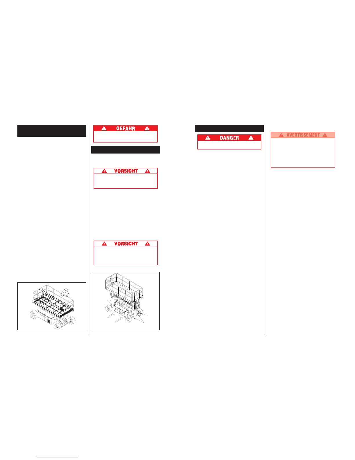
22
Herunterklappen des
Schutzgeländers
Dieses Verfahren nur zum Durchfahren von Toren
verwenden. Schutzgeländer müssen wieder in ihre
richtige Position gebracht werden, bevor der Korb
benutzt wird.
Herunterklappverfahren (Bild 4)
Hinweis: Bei der Durchführung dieses Verfahrens
alle Befestigungsteile aufheben.
1. Stellen Sie den Controller auf die Wagenbühne.
2. Beginnen Sie auf der Vorderseite der
Wagenbühne, entfernen Sie Schraubenmuttern,
Schrauben und Unterlegscheiben von der
Oberseite der vorderen Schutzgeländer.
3. Schließen Sie das Gitter und klinken Sie es ein.
4. Entfernen Sie Schraubenmuttern, Schrauben und
Unterlegscheiben von der Oberseite der hinteren
Schutzgeländer. Klappen Sie das hintere
Schutzgeländer auf die Wagenbühne herunter, und
halten Sie das Gitter in der Zwischenzeit
eingeklinkt.
5. Entfernen Sie Schraubenmuttern, Schrauben und
Unterlegscheiben von der Oberseite der seitlichen
Schutzgeländer und von Gleitdeck des Mittelgeländers.
Heben und klappen Sie eine Seite der Schutzgeländer
ein, so daß es auf dem Deck liegt. Wiederholen Sie
diese Schritte mit dem anderen Seitengeländer.
Aufrichtverfahren
1. Heben Sie die Seitengeländer und versichern Sie
sich, daß jedes nach unten geschoben ist, um das
Schutzgeländer in vertikaler Position zu sichern.
2. Installieren Sie Schrauben, Unterlegscheiben und
Schraubenmuttern zwischen den Seitengeländern,
ziehen Sie sie gut fest.
3. Heben Sie den hinteren Schutzgeländeraufbau,
richten Sie die Löcher aus und installieren Sie die
Schrauben, Unterlegscheiben und
Schraubenmuttern. Ziehen Sie sie gut fest.
4. Heben Sie das vordere Schutzgeländer, richten Sie
die Löcher aus und installieren Sie die Schrauben,
Unterlegscheiben und Schraubenmuttern. Ziehen
Sie sie gut fest.
5. Hängen Sie den Controller an das vordere Schutzgeländer.
6. Bevor Sie die Arbeitsbühne in Betrieb nehmen,
überprüfen Sie, daß alle Feststellriegel richtig
angebracht und festgezogen sind.
Transport der Gelenk-Hubbühne
Per Gabelstapler
Hinweis: Maschine nur zum Transport anheben.
Das Gewicht der Hubbühne anhand der
technischen Daten überprüfen und sicherstellen,
daß der Gabelstapler zum Heben dieses
Gewichtes geeignet ist.
Heben Sie die Maschine von der Seite des Fahrwerks,
indem Sie sie mit der Gabel unter den Fahrwerkmodulen anheben (Bild 5)
Per Kran
Sichern Sie die Haltebänder nur an den FahrwerkHebezapfen (Bild 5).
Per Lastwagen
1. Manövrieren Sie die Hubbühne in Transportposition
und blockieren Sie die Räder.
2. Befestigen Sie die Gelenk-Hubbühne mit Ketten
oder Haltebändern mit angemessener Zugleistung
an dem Transportfahrzeug, indem Sie sie durch die
Halteringe am Fahrzeug ziehen (Bild 5).
Niemals die Halteringe zum Anheben der
Gelenk-Hubbühne benutzen.
Ein zu starkes Festziehen der Ketten oder
Haltebänder kann zu einer Beschädigung der
Gelenk-Hubbühne führen.
Bild 4: Herunterklappen des Schutzgeländers Bild 5: Transport der Gelenk-Hubbühne
Vordere
Halteringe/
Hebezapfen
Anheben
per
Gabelstapler
Hintere
Hebezapfen
(üblicherweise
hier)
Hintere
Halteringe
Vor Betreten des Korbes müssen die
Schutzgeländer an richtiger Stelle angebracht
und fest verankert sein.
15
Entretien
Ne jamais entretenir la plate-forme lorsqu’elle
est élevée.
N.B. : Aucun entretien normal (de routine) n’est
nécessaire sur le SL26/30RT avec la plate-forme
élevée.
Entretien de la batterie
Danger : mélange de gaz explosifs. Garder les
étincelles, les flammes et les articles de fumeur
éloignés des batteries.
Toujours porter des lunettes de sécurité lors du
travail sur les batteries.
Le fluide de batteries est hautement corrosif.
Rincer soigneusement tous les débordements
de fluide à l’eau claire
Inspection et nettoyage de la batterie
Vérifier quotidiennement le niveau de fluide de la
batterie, en particulier si la plate-forme de travail est
utilisée dans un climat chaud et sec. Si le niveau
d’électrolyte est à moins de 10 mm (3/8 pouce) audessus des plaques, ajouter uniquement de l’eau
distillée propre. Ne pas utiliser d’eau du robinet avec
une teneur élevée en minéraux car cela réduirait la
durée de vie de la batterie.
La batterie doit être inspectée régulièrement pour tous
signes de fissures de la boîte, de fuites d’électrolyte et
de corrosion des terminaux. Inspecter les câbles en
recherchant les endroits usés et les cassures de
l’isolation et des terminaux.
Nettoyer la batterie lorsque vous observez des signes
de corrosion des terminaux ou lorsque les électrolytes
ont débordé lors du chargement. Utiliser une solution
de bicarbonate de soude pour nettoyer la batterie en
faisant attention de ne pas introduire cette solution
dans les cellules de la batterie. Rincer abondamment à
l’eau claire. Nettoyer les surfaces de contact de la
batterie et des câbles jusqu’à ce que le métal brille
lorsque vous retirez un des câbles.
Page 16
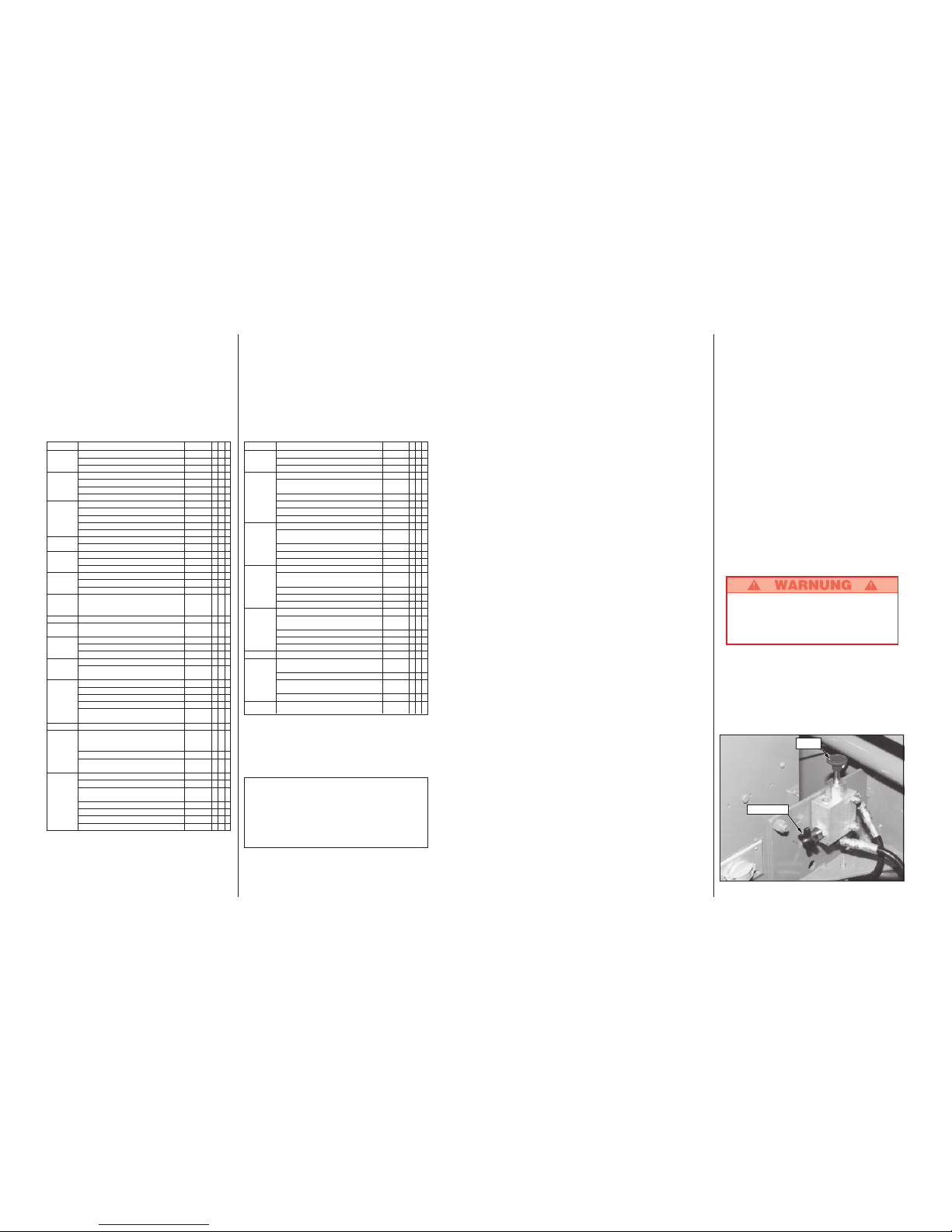
16
Entretien régulier
Utiliser le tableau ci-dessous comme guide d’entretien
régulier. L’inspection et l’entretien doivent être
effectués par le personnel qualifié connaissant bien
les procédures mécaniques et électriques. Référez-
vous au Manuel d’entretien pour les instructions
complètes.
Veuillez copier cette page et utiliser le tableau
d’entretien régulier comme une liste pense-bête
lorsque vous inspectez la machine pour entretien.
COMPOSANT MAINTENANCE INTERVALLE O N R
Huile moteur Vérifier le niveau et l’état 1 J
Vérifier les fuites 1 J
Changer le filtre à huile et l'huile 100 HEURES
Système Vérifier le niveau de carburant 1 J
de carburant Vérifier les fuites 1 J
Changer le filtre à carburant 6 M
Vérifier le filtre à air 1 J
Système des Vérifier le niveau d’électrolyte 1 J
Batteries Vérifier la densité 30 J
du moteur Nettoyer l’extérieur 6 M
Vérifier les connexion des câbles 1 J
Nettoyer les terminaux 6 M
Liquide de Vérifier le niveau du liquide (à froid) 1 J
refroidissement Vidanger le liquide 3 M
Huile Vérifier le niveau d’huile 1 J
hydraulique Changer le filtre 6 M
Vidanger l’huile 2 A
Système Vérifier les fuites 1 J
hydraulique Vérifier les connexions des tuyaux 30 J
Vérifier l’usure extérieure des tuyaux 30 J
Système Ouvrir la vanne d’abaissement 1 J
hydraulique d’urgence et vérifier son
d’urgence fonctionnement
Contrôleur Vérifier le fonctionnement du commutateur 1 J
Câble de Vérifier l’extérieur du câble : 1 J
contrôle pincement coincement et usure
Plancher et
Vérifier que les vis soient serrées 1 J
garde-corps de
Vérifier que les soudures ne soient fissurées 1 J
l
a plate-forme
Vérifier l’état de la surface de la plate-forme 1 J
Pneus Vérifier l’état 1 J
Vérifier que les boulons soient 30 J
serrés à 123 Nm (90 pieds*livres)
Pompe Essuyer 30 J
hydraulique Vérifier les fuites et les connexions 30 J
Vérifier les joints des tuyaux 1 J
Vérifier que les boulons soient serrés 30 J
Vérifier le moment et l’alignement
du couplage moteur 1 A
Moteurs Vérifier le fonctionnement et les fuites 1 J
Système Vérifier que les composants et raccords soient 6 M
de direction serrés au couple adéquat
Graisser les pivots 30 J
Graisser la barre transversale 30 J
Vérifier les fuites du vérin de direction 30 J
et que les boulons soient bien serrés
Ensemble Inspecter les fissures structurelles 1 J
de levage Vérifier l’usure des axes de rotation 30 J
Vérifier que les boulons des 30 J
axes de rotation soient bien serrés
Vérifier l’usure des engrenages 6 M
Vérifier la torsion des bras de levage 6 M
Graisser les axes de transmission 30 J
Graisser les engrenages de transmission 30 J
Légende du tableau d’entretien régulier
Intervalle
1J = chaque poste (une fois par jour) ou toutes les
huit heures
30J = tous les mois (30 jours) ou toutes les 50 heures
3M = tous les 3 mois ou 125 heures
6M = tous les 6 mois ou 250 heures
1A = tous les ans ou 500 heures
2A = tous les deux ans ou 1000 heures
O = Oui/acceptable
N = Non/inacceptable
R = Réparer/acceptable
COMPOSANT MAINTENANCE INTERVALLE O N R
Châssis
Vérifier les pincements et les frottements des tuyaux
1 J
Vérifier que les composants soient bien serrés 6 M
Vérifier les fissures des soudures 1 J
Vérin de Vérifier l’usure du vérin 30 J
levage Vérifier que les boulons de l’axe 30 J
de rotation sont bien serrés
Vérifier les anneaux de l’axe de rotation 30 J
Vérifier les fuites aux joints 30 J
Vérifier l’usure des axes de rotation 30 J
Vérifier que les connexions soient bien serrées 30 J
Vérin avant/ Vérifier l’usure du vérin 30 J
arrière Vérifier que les boulons de l’axe 30 J
de rotation soient bien serrés
Vérifier les fuites aux joints 30 J
Vérifier l’usure des axes de rotation 30 J
Vérifier que les connexions soient bien serrées 30 J
Vérin Vérifier l’usure du vérin 30 J
côté/côté Vérifier que les boulons de l’axe 30 J
de rotation soient bien serrés
Vérifier les fuites aux joints 30 J
Vérifier l’usure des axes de rotation 30 J
Vérifier que les connexions soient bien serrées 30 J
Vérin Vérifier l’usure du vérin 30 J
d’axe Vérifier que les boulons de l’axe 30 J
de rotation soient bien serrés
Vérifier les fuites aux joints 30 J
Vérifier l’usure des axes de rotation 30 J
Vérifier que les connexions soient bien serrées 30 J
Niveau à bulle
Vérifier les dommages des joints de la bulle et de la cible
1 J
Unité Vérifier et réparer les 1 J
complète dommages de collision
Vérifier que les vis soient bien serrées 3 M
Vérifier la corrosion : 6 M
nettoyer et repeindre
Lubrifier 30 J
Etiquettes Vérifier le détachement, la perte et la 1 J
lisibilité des étiquettes : remplacer
Rapport d’entretien
Date: ______________
Propriétaire: ____________________________
Nº modèle: ___________Nº série: __________
Entretenu par: ___________________________
Intervalle de service : _____________________
21
Ausrichten der Gelenk-Hubbühne in
die Waagrechte
Bringen Sie den Fahr/Ausricht/Hebeschalter in die
AUSRICHT-Stellung (LEVEL) und halten Sie den
Steuerungshebel so, daß der Interlockhebel
heruntergedrückt ist. Bringen Sie die Blase der
Wasserwaage mit Hilfe der Vor/Zurück- und Rechts/
Linksschalter in die Mitte. Um die Hubbühne nach
vorne auszurichten, kann es notwendig sein, den Korb
etwas anzuheben.
Heben und Senken des Korbes
1. Bringen Sie den Fahr/Hebeschalter auf HEBEN/
SENKEN (LIFT).
2. Während Sie den Steuerungshebel so halten, daß
der Interlockhebel eingedrückt ist, drücken Sie den
Steuerungshebel langsam auf AUF (UP) zum
Heben des Korbes. Je weiter der Hebel gedrückt
wird, desto schneller wird der Korb angehoben.Läßt
sich der Korb nicht über die Interlockhöhe von ca.
2,44 m anheben, senken Sie ihn wieder ganz ab
und richten Sie die Hubbühne neu aus.
3. Sobald der Arbeitseinsatz abgeschlossen ist,
bringen Sie den Fahr/Ausricht/Hebeschalter auf
HEBEN/(LIFT) und lassen den Korb herunter,
indem Sie den Steuerungshebel zurückziehen, bis
der Korb ganz unten ist.
Fahren mit ausgefahrenem Korb
NUR auf festem und ebenem Untergrund mit
ausgefahrenem Korb fahren.
Hinweis: Die Gelenk-Hubbühne fährt in ausgefahrenem Zustand mit geringerer Geschwindigkeit. Die
SL30-Modelle fahren nur, wenn der Korb nicht
weiter als 8 m ausgefahren ist.
1. Versichern Sie sich, daß die Fahrstrecke eben, frei
von Personen, Löchern und Abhängen ist und das
Gewicht der Maschine aushält.
2. Überprüfen Sie den Freiraum über, unter und um
die Hubbühne herum.
3. Bringen Sie den Fahr/Ausricht /Hebeschalter in die
FAHR-Stellung (DRIVE).
4. Drücken Sie den Steuerungshebel auf
VORWÄRTS (FORWARD) oder RÜCKWÄRTS
(REVERSE), je nach gewünschter Fahrtrichtung.
Hinweis: Wenn die Maschine zu fahren aufhört und
der Neigungsalarm ertönt, sofort den Korb
absenken und die Maschine neu ausrichten, bevor
der Korb wieder ausgefahren wird.
Senken im Notfall
Der Notfall-Senk-Schalter befindet sich auf der
linken Seite des Fahrwerks durch den Ausschnitt in
der Steuerungsmodulabdeckung.
1. Öffnen Sie das Notfall-Senk-Ventil, indem Sie den
Notfall-Senk-Schalter herunterdrücken.
2. Sobald der Korb voll abgesenkt ist, lassen Sie den
Schalter los, um das Notfall-Senkventil zu
schließen. Der Korb läßt sich nicht ausfahren, wenn
das Notfall-Senkventil nicht geschlossen ist.
Täglich nach jeder Benutzung
1. Versichern Sie sich, daß der Korb vollständig
abgesenkt wurde.
2. Parken Sie die Maschine ebenerdig, vorzugsweise
unter einer Abdeckung. Sichern Sie sie vor
Vandalismus, Kinder und unbefugte Benutzung.
3. Drehen Sie den Schlüsselschalter auf AUS (OFF)
und ziehen Sie den Schlüssel ab, um eine unbefugte
Inbetriebnahme der Maschine zu verhindern.
Lösen der Parkbremse (Bild 3)
Führen Sie folgendes nur aus, wenn sich die Maschine
nicht aus eigener Kraft betreiben läßt und ein Fortbewegen der Maschine notwendig ist oder wenn die
Maschine eine Steigung hochgeschleppt oder mit einer
Winde zum Abtransport auf einen Anhänger gezogen
wird.
1. Schließen Sie das Nadelventil durch Drehen des
Knopfes im Uhrzeigersinn.
2. Pumpen Sie die Bremslösepumpe, bis sich die
Parkbremsen lösen und die Räder gedreht werden
können.
3. Die Maschine läßt sich nun durch Ziehen oder
Schieben rollen.
4. Achten Sie darauf, daß Sie das Nadelventil öffnen
und daß die Parkbremsen angezogen sind, bevor
die Maschine wieder in Betrieb genommen wird.
Niemals die Gelenk-Hubbühne bei nicht
funktionierenden Parkbremsen betreiben.
Schwere Verletzungen oder Schäden können
die Folge sein.
Niemals schneller als 0,3 m/s schleppen.
Pumpe
Nadelventil
Bild 3: Bremslösepumpe
Page 17

20
8. Haken Sie die Steuerung wieder am vorderen
Schutzgeländer ein.
9. Drücken Sie den Fahrwerk-Hebeschalter in die AUF-
Stellung (UP) und heben Sie den Korb an. Der Korb
darf nur bis zur Interlockhöhe von 2,44 m über dem
Erdboden ausfahren, bevor der Neigungsalarm ertönt.
Fährt der Korb weiterhin aus, bzw. es ertönt kein
Alarm, STOPPEN (STOP) Sie sofort und ziehen Sie
die Maschine aus dem Verkehr, bis sie repariert
wurde.
10. Senken Sie den Korb mit dem Fahrwerk-Hebeschalter.
11. Betreten Sie den Korb. Mit der Wasserwaage als
Richtschnur richten Sie die Hubbühne mit den Seite/
Seite- und Vor/Zurückschaltern waagerecht aus.
Verlassen Sie den Korb.
12. Fahren Sie den Korb mit dem Fahrwerk-Hebeschalter
ganz aus.
13. Inspizieren Sie visuell die ausgefahrene Hubbühne,
den Hebezylinder, die Kabel und Schläuche auf
Schäden und unregelmäßige Funktion. Achten Sie
auf fehlende oder lockere Teile.
14. Senken Sie den Korb teilweise ab, indem Sie den
Fahrwerk-Hebeschalter auf AB (DOWN) drücken.
Überprüfen Sie die Funktion des akustischen
Senkalarms.
15. Drücken Sie den Fahrwerk-Notfall-Senk-Schalter
herunter, um die korrekte Funktion zu überprüfen.
Sobald der Korb ganz abgesenkt wurde, lassen Sie
den Schalter los.
16. Drücken Sie den Fahrwerk-Notfall-Aus-Knopf.
17. Bedienen Sie die Steuerung, um die Funktionsfähigkeit
des Notfall-Aus-Knopfes zu überprüfen, indem Sie nur
einen der Notfall-Aus-Knöpfe in die AUS-Stellung (OFF)
drücken. Wiederholen Sie diesen Test, indem Sie den
anderen Notfall-Aus-Knopf in die AUS-Stellung (OFF)
drücken. Sollte dennoch eine der Maschinenfunktionen
bei eingedrücktem Notfall-Aus-Knopf arbeiten,
unabhängig davon, welcher der beiden Knöpfe benutzt
wurde, STOPPEN Sie die Maschine sofort und ziehen
Sie sie aus dem Verkehr, bis sie repariert wurde.
18. Schließen und sichern Sie die Modulabdeckungen.
19. Drehen Sie den Steuerungsschlüsselschalter
gegen den Uhrzeigersinn auf AUS (OFF).
Bedienung
Vor dem Bedienen der Gelenk-Hubbühne stellen Sie
sicher, daß alle Vor-Inbetriebnahme- und Sicherheitsinspektionen vollständig durchgeführt und jegliche
Mängel beseitigt worden sind. Stellen Sie auch sicher,
daß der Bediener der Gelenk-Hubbühne sorgfältig an
der Maschine ausgebildet worden ist.
Fahren mit abgesenktem Korb
1. Versichern Sie sich, daß der Fahrwerk-Notfall-AusSchalter in AN-Stellung (ON) ist. Ziehen Sie den
Knopf heraus.
2. Nach dem Betreten des Korbes schließen und
sichern Sie das Tor. Überprüfen Sie, daß alle
Schutzgeländer an Ort und Stelle und richtig
montiert und verschraubt sind.
3. Stellen Sie sicher, daß die Fahrstrecke frei von
Personen, Hindernissen, Löchern und Abhängen ist
und das Gewicht der Räder aushält.
4. Überprüfen Sie den Freiraum über, unter und um
die Hubbühne herum.
5. Ziehen Sie den Steuerungs-Notfall-Aus-Knopf
heraus in die AN-Stellung (ON).
6. Drehen Sie den Steuerungsschlüsselschalter im
Uhrzeigersinn ganz herum, um den Motor zu
starten. Lassen Sie den Schlüssel los, sobald der
Motor startet.
Hinweis: Bei Diesel Modellen, wenn der Motor kalt
ist, drücken und halten Sie den Vorglühknopf 6
Sekunden lang, um die Glühkerzen zu entzünden.
7. Bringen Sie den Fahr/Hebe/Geschwindigkeitsbereichsschalter auf HOHES DREHMOMENT
(HIGH TORQUE).
8. Nehmen Sie den Kontrollhebel so in die Hand, daß
der Interlockhebel heruntergedrückt ist. (Eine
Freigabe des Interlockhebels unterbricht die Leistung
der Steuerung). Drücken oder ziehen Sie den
Steuerungshebel langsam in die VORWÄRTS- oder
RÜCKWÄRTS-Stellung (FORWARD/REVERSE), um
in die gewünschte Richtung zu fahren. Je weiter Sie
den Steuerungshebel von der Mitte weg drücken oder
ziehen, desto schneller fährt die Maschine.
9. Während der Fahrt drücken Sie den Fahr/Hebe/
Geschwindigkeitsbereichsschalter auf HOHE
GESCHWINDIGKEIT (HIGH SPEED) für das
Befahren von ebenem Untergrund oder auf HOHES
DREHMOMENT (HIGH TORQUE) für das Befahren
von Steigungen oder das Fahren in engen Bereichen.
Lenkung
Drücken Sie den Lenkungsschalter nach RECHTS
(RIGHT) oder LINKS (LEFT), um die Räder zu drehen.
Beobachten Sie die Reifen beim Manövrieren, um die
gewünschte Richtung sicherzustellen.
Hinweis: Die Lenkung stellt sich nicht automatisch
zurück. Die Räder müssen mit dem Lenkungsschalter
wieder nach vorne ausgerichtet werden.
Bild 2: Steuerung
Interlockhebel
Lenkungsschalter
Steuerungshebel
Schlüsselschalter
Geschwindigkeitsbereichs-
schalter
Fahr/
Hebeschalte
Notfall-Aus-
Schalter
Vorglühknopf
17
*Caractéristiques sujettes à modifications sans préavis.
Voir le Manuel d’entretien pour des informations complètes sur l’entretien et sur les
pièces de rechange.
Caractéristiques*
ARTICLE
Taille de la plate-forme (intérieur)
Standard
avec extension
Cap. max. de la plate-forme
Standard
avec extension
sur l’extension
No. max. d’occupants
Standard
avec extension
Hauteur
Hauteur de travail
Hauteur max. de plate-forme
Hauteur min. de plate-forme
Dimensions
Poids
Largeur hors-tout
Hauteur hors-tout
Longueur hors-tout
Hauteur max. déplacement
Vitesse au sol
Plate-forme baissée
Plate-forme levée
Tension du circuit
Cap. du réservoir hydraulique
Pression maximum du circuit
hydraulique
Liquide hydraulique
Utilisation normale (> 32° F [0° C])
Utilisation temp. froide
(-10 à 32° F [-23 à 0° C])
Système de levage
Vitesse de levage
Mise à niveau de Plate-Forme
Moteur
Contrôle de déplacement
Système de commande
Déplacement horizontal
Pneus
Frein de stationnement
Rayon de braquage (intérieur)
Pente maximum
Empattement
Garde-corps
Garde-pieds
SL30SL
1,71 m x 4,22m[67,5 in. x 166,25 in.]
N/A
590 kg [1300 lbs.]
N/A
N/A
5 personnes
N/A
10,97 m [36 ft.]
9,14 m [30 ft.]
1,5 m [59 in.]
3.216 kg [7.090 lbs.]
2,13 m [84 in.]
2,60 m [102,5 in.]
4,39 m [173 in.]
7,93 m [26 ft.]
0 to 5,0 km/h [0 to 3,1 mph]
0 to 0,8 km/h [0 to 0,5 mph]
12 Volt DC
45,5 L [12 gal.]
172 bar [2500 psi]
ISO #46
5W-20 Motor Oil
Un vérin de levage à simple étage
Montée. 24 sec./ descente. 36 sec.
13° côté/côté ; 9° avant/arrière
20 HP Kubota Diesel. 3 Cylindres. Refroidissement à eau
Proportionnel
Contrôleur de manette de commande avec levier
de verrouillage ; commutateurs de sélection et
d’arrêt d’urgence et niveau à bulle (ne fonctionne
pas au-dessus de la hauteur de verrouillage)
Moteurs hydrauliques sur les quatre roues
26 x 12,00 - 12 NHS Super Terra accrochant,
rempli de mousse
Appliqués par deux ressorts et relâchés
hydrauliquement, avec plusieurs disques
3,96 m [13 ft.]
19° [35%]
2,54 m [100 in.]
Hauteur: 1,11 m [43,5 in.] Basculant avec portillon
Hauteur: 152 mm [6 in.]
SL26SL
1.71 m x 3,59m[67,5 in. x 141,5 in.]
1,71 m x 4,61 m [67,5 in. x 181,5 in.]
680kg [1500 lbs.]
680kg [1500 lbs.]
227 kg [500 lbs.]
5 personnes
2 personnes
9,75 m [32 ft.]
7,93 m [26 ft.]
1,5 m [59 in.]
3.075 kg [6.780 lbs.]
2,13 m [84 in.]
2,60 m [102,5 in.]
3,79 m [149 in.]
7,93 m [26 ft.]
0 to 5,0 km/h [0 to 3,1 mph]
0 to 0,8 km/h [0 to 0,5 mph]
12 Volt DC
45,5 L [12 gal.]
172 bar [2500 psi]
ISO #46
5W-20 Motor Oil
Un vérin de levage à simple étage
Montée. 21 sec./ descente. 32 sec.
13° côté/côté ; 9° avant/arrière
20 HP Kubota Diesel. 3 Cylindres. Refroidissement à eau
Proportionnel
Contrôleur de manette de commande avec levier
de verrouillage ; commutateurs de sélection et
d’arrêt d’urgence et niveau à bulle (ne fonctionne
pas au-dessus de la hauteur de verrouillage)
Moteurs hydrauliques sur les quatre roues
26 x 12,00 - 12 NHS Super Terra accrochant,
rempli de mousse
Appliqués par deux ressorts et relâchés
hydrauliquement, avec plusieurs disques
3,96 m [13 ft.]
19° [35%]
2,54 m [100 in.]
Hauteur: 1,11 m [43,5 in.] Basculant avec portillon
Hauteur: 152 mm [6 in.]
Page 18
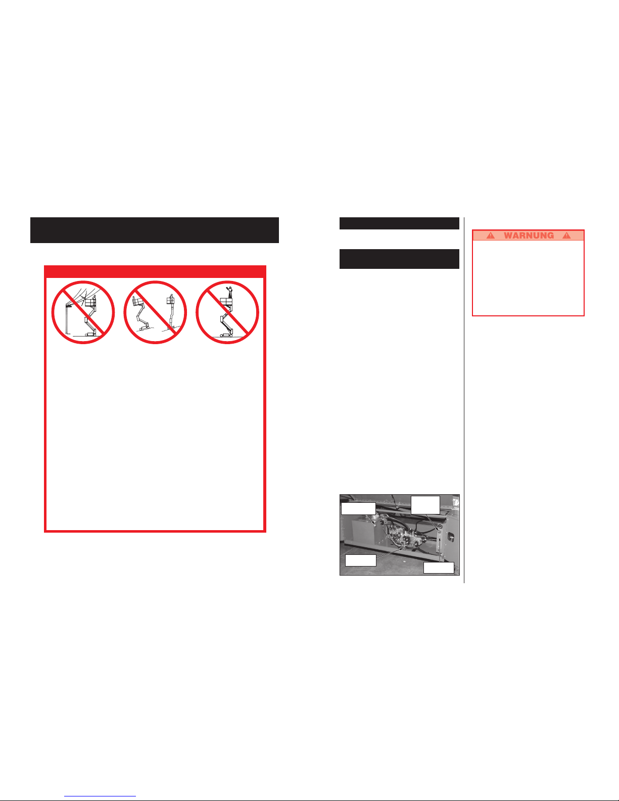
18
Deutschsprachiger Teil
NIEMALS Maschine
innerhalb von drei Metern
von Hochspannungsleitungen
betreiben. DIESE
MASCHINE IST NICHT
ISOLIERT.
NIEMALS auf die
Schutzgeländer oder die
mittlere Querstange klettern,
setzen oder stellen.
NIEMALS Korb ausfahren oder
Maschine mit ausgefahrenem
Korb auf unebenem Gefälle oder
wei-chem Untergrund fahren oder
den Korb ausfahren, ohne daß die
Ma-schine gerade stecht.
SICHERHEITSREGELN
NIEMALS die Maschine ohne vorheriges Absuchen des Arbeitsbereichs nach Gefahrenstellen
wie Löchern, Abhängen, Unebenheiten oder Schutt betreiben.
NIEMALS die Maschine benutzen, wenn das Schutzgeländer nicht richtig oder unvollständig
angebracht und nicht richtig verankert worden ist.
IMMER das Tor des Einstiegs nach Betreten des Korbes schließen und sichern.
NIEMALS eine Leiter oder ein Gerüst im Korb benutzen.
NIEMALS überstehende Lasten anbringen oder den Korb vergrößern.
IMMER in alle Richtungen (oben, unten, rundherum) nach Hindernissen und elektrischen
Leitungen Ausschau halten.
IMMER alle Lasten gleichmäßig im Korb verteilen. Siehe Rückseite für maximale Tragfähigkeit der
Hubbühne.
NIEMALS beschädigtes Gerät verwenden. (Wenden Sie sich an UpRight für Anweisungen.
Siehe Telefonnummern auf der Rückseite.)
NIEMALS Betriebs- oder Sicherheitssysteme modifizieren.
IMMER die Maschine gründlich nach gerissenen Schweißnähten, lockeren Schraubverbindungen,
Hydrauliklecks, beschädigten Steuerungskabeln, lockeren Kabelverbindungen und lockeren
Radbolzen untersuchen.
NIEMALS den ausgefahrenen Gelenkmast herunterklettern.
NIEMALS die Maschine bei ausgefahrenem Gelenkmast warten, ohne vorher den
Ausfahrmechanismus zu blockieren.
NIEMALS die Batterien in Funken- oder Feuernähe wiederaufladen. Die Batterien verströmen
beim Aufladen ein hochexplosives Wasserstoffgas.
IMMER die Hubbühne nach Gebrauch durch Abziehen des Schlüssels vor unbefugter
Benutzung sichern.
NIEMALS Komponenten oder Teile durch Nicht-Original-UpRight-Ersatzteile ohne Zustimmung
des Herstellers ersetzen.
19
Einführung
Diese Bedienungsanleitung behandelt die SL26/30SL
Gelenk-Hubbühnen . Diese Betriebsanleitung muß
immer bei der Maschine aufbewahrt werden.
Vor-Inbetriebnahme- und
Sicherheitsinspektion
Lesen, verstehen und befolgen Sie alle
Sicherheitsregeln und Betriebsanweisungen.
Danach gehen Sie jeden Tag folgende Schritte vor
Inbetriebnahme der Maschine durch:
1. Entfernen Sie die Modulabdeckungen und
untersuchen Sie sie auf Schäden, Öl-Lecks oder
fehlende Teile.
2. Überprüfen Sie den Hydraulikölstand bei voll
abgesenkter Hubbühne. Öl sollte im Sichtglas zu
sehen sein. Be Bedarf Hydrauliköl nachfüllen (siehe
technische Daten, Deckblatt-Rückseite).
3. Überprüfen Sie den Flüssigkeitsstand der Batterien
(s. Batteriewartung , Seite 23).
4. Inspizieren Sie die gesamte Gelenk-Hubbühne
genauestens auf Schäden wie gerissene
Schweißnähte oder Strukturteile, lockere oder fehlende
Teile, Öl-Lecks, beschädigte Kabel oder Schläuche,
lockere Verbindungen und Reifenschäden.
5. Versichern Sie sich, daß alle Schutzgeländer an
Ort und Stelle und richtig verankert sind.
6. Ziehen Sie den Fahrwerk-Notfall-Aus-Knopf heraus,
in die AN-Stellung (ON).
Inspektion des Motors
1. Überprüfen Sie die Kraftstoffversorgung.
2. Überprüfen Sie den Motorölstand mit dem
Meßstab.
3. Überprüfen Sie den Kühlwasserstand bei kaltem
Motor. NIEMALS den Kühlwasserstand bei heißem
Motor oder Kühler überprüfen.
Inspektion der Systemfunktion
Außerhalb der Reichweite der Gelenk-Hubbühne
bleiben, wenn folgende Überprüfungen durch
geführt werden.
Vor Inbetriebnahme der Gelenk-Hubbühne den
Arbeitsbereich nach Gefahrenstellen wie
Löchern, Abhängen, Unebenheiten und Schutt
absuchen.
In ALLE Richtungen (oben, unten, rund herum)
nach Hindernissen und elektrischen Leitungen
Ausschau halten.
Das Steuerungskabel vor etwaiger Beschädigung
während der Durchführung der Überprüfungen
schützen.
1. Nehmen Sie die Steuerung vom vorderen
Schutzgeländer. Nehmen Sie die Steuerung fest in
die Hand, so daß der Interlockhebel heruntergedrückt
werden kann, während Sie die folgenden
Überprüfungen vom Boden aus durchführen.
2. Ziehen Sie den Steuerungs-Notfall-Aus-Knopf
heraus in die AN-Stellung (ON).
3. Drehen Sie den Steuerungsschlüsselschalter im
Uhrzeigersinn ganz herum, um den Motor zu
starten. Lassen Sie den Schlüssel los, sobald der
Motor startet.
Hinweis: Bei Diesel Modellen, wenn der Motor kalt
ist, drücken und halten Sie den Vorglühknopf 6
Sekunden lang, um die Glühkerzen zu entzünden.
4. Bringen Sie den Fahr/Ausricht/Hebeschalter in die
FAHR-Stellung (DRIVE).
5. Aktivieren Sie den Interlockhebel, indem Sie den
Geschwindigkeitsbereichsschalter erst in HOHES
DREHMOMENT (HIGH TORQUE) und dann in
HOHE GESCHWINDIGKEIT (HIGH SPEED)
bringen. Dann drücken Sie den Steuerungshebel
langsam in die VORWÄRTS- und danach in die
RÜCKWÄRTS-Stellung (FORWARD/REVERSE),
um die Geschwindigkeit und Richtungskontrolle zu
überprüfen. Je weiter Sie den Steuerungshebel von
der Mitte weg drücken oder ziehen, desto schneller
fährt die Maschine.
6. Drücken Sie den Lenkungsschalter nach RECHTS
(RIGHT) dann LINKS (LEFT), um die
Lenkungssteuerung zu überprüfen.
7. Bringen Sie den Fahr/Ausricht/Hebeschalter auf
AUSRICHTEN (LEVEL). Während des
Herunterdrückens des Interlockhebels aktivieren Sie
die Vor/Zurück- und Seite/Seite-Schalter, um ihre
richtige Funktion sicherzustellen. Benutzen Sie den
Seite/Seite-Schalter und neigen Sie die GelenkHubbühne zu einer Seite.
Bild 1: Steuerungsmodul, linke Seite des Fahrwerks
Sichtglas,
Hydrauliktank
Notfall-Senk-
Schalter
Fahrwerk-
Notfall-Aus-
Knopf
Fahrwerk-
Hebeschalter
 Loading...