

Page 1
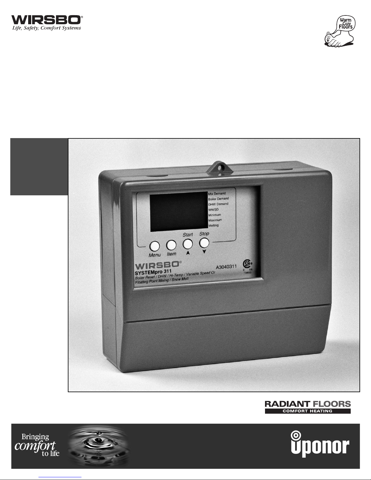
SYSTEMpro™311
Installation Manual
Page 2

SYSTEMpro™311
Installation Manual
is published by Uponor Wirsbo
5925 148th Street West
Apple Valley, MN 55124
(952)-891-2000
© 2002 Uponor Wirsbo, All rights reserved.
First Edition
First Printing July 2002
Printed in the United States of America
Page 3
TABLE OF CONTENTS
INTRODUCTION
Control Overview .................................................................... 3
Navigating the Control ........................................................ 4-6
Viewing the Status of the System Performance .......... 7-12
Mixing Reset Mode ........................................ 7-9
Snow Melt Mode ........................................10-12
INSTALLATION
Step 1 – Checking Contents ................................................ 14
Step 2 – The Control Base .............................................. 15-17
Step 3 – Rough-In Wiring...................................................... 18
Step 4 – Attaching the Control to the Base ...................... 19
Step 5 – Mounting the Sensors .................................... 20-22
Step 6 – Electrical Connections to the Control............ 23-28
Powered Input Connection ............................ 23
Output Connections .................................. 24-25
Sensor Connections ........................................ 26
Unpowered Input Connections .................... 27
Temperature Resistance Chart ...................... 28
Step 7 – Testing the Wiring ............................................ 29-32
Test the Sensors .............................................. 29
Test the Power Supply .................................... 30
Test the Powered Demand Inputs ................ 30
Test the Outputs ........................................ 30-32
Step 8 – Completing the Installation .................................. 33
PROGRAMMING
Step 1 – Programming the Control .............................. 35-55
DIP Settings ................................................ 35-36
Programming the "Misc" Menu .................... 37
Programming the "Adjust" Menu............ 38-55
A. Boiler/High Temp Zone Settings.... 38-41
B. DHW Settings.................................... 42-43
C. Mixing Device Settings.................... 44-49
D. Snow Melting Settings.................... 50-53
E. Boiler Operation Settings ................ 54-55
Step 2 – Test Sequence.................................................... 56-57
CONTROL FUNCTION OVERVIEW
Section A – General .............................................................. 59
Section B – Boiler / High Temp Zones .......................... 60-62
Section B1 – General ................................ 60-62
Section B2 – Boiler Demands ........................ 62
Section C – Domestic Hot Water (DHW) ...................... 63-66
Section C1 – General ................................ 63-64
Section C2 – DHW Priority ........................ 65-66
Section D – Mixing Zones .............................................. 67-71
Section D1 – General ................................ 67-69
Section D2 – Mixing Devices.................... 69-70
Section D3 – Mixing Demands ................ 70-71
(Continued on page 2)
1
INTRODUCTION
INTRODUCTION - Table of Contents
IMPORTANT NOTE:
If you are not familiar with how
the Wirsbo SYSTEMpro 311
operates, or the theory behind
settings for a radiant system it is
important you review the Control
Function Overview. It will help
with understanding the functions
of the control within the hydronic
radiant heating system.
Quick Guide
If you are only INSTALLING
the SYSTEMpro 311 go to:
INSTALLATION
Steps 1-8
If you are only PROGRAMMING
the SYSTEMpro 311 go to:
PROGRAMMING
Steps 1-2
Page 4
Section E – Snow Melting .............................................. 72-79
Section E1 – General.................................. 72-75
Section E2 – With Slab Sensor ................ 76-77
Section E3 – Without Slab Sensor .......... 77-78
Section E4 – Snow Melt Enable .............. 78-79
Section F – Boiler Operation .......................................... 80-81
Section F1 – Boiler Supply Sensor.......... 80-81
Section G – Troubleshooting .......................................... 82-83
APPENDIX
IVariable Speed Injection Mixing.............................. 85-87
II SYSTEMpro 311 Menu Tree .................................... 88-89
III Application Drawings ................................................ 90-97
IV Error Message Overview ........................................ 98-101
V SYSTEMpro 311 Program Setup ........................ 102-103
2
INTRODUCTION
INTRODUCTION - Table of Contents
TABLE OF CONTENTS (cont.)
Page 5
INTRODUCTION
CONTROL OVERVIEW
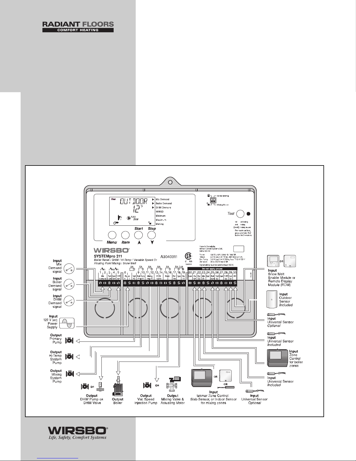
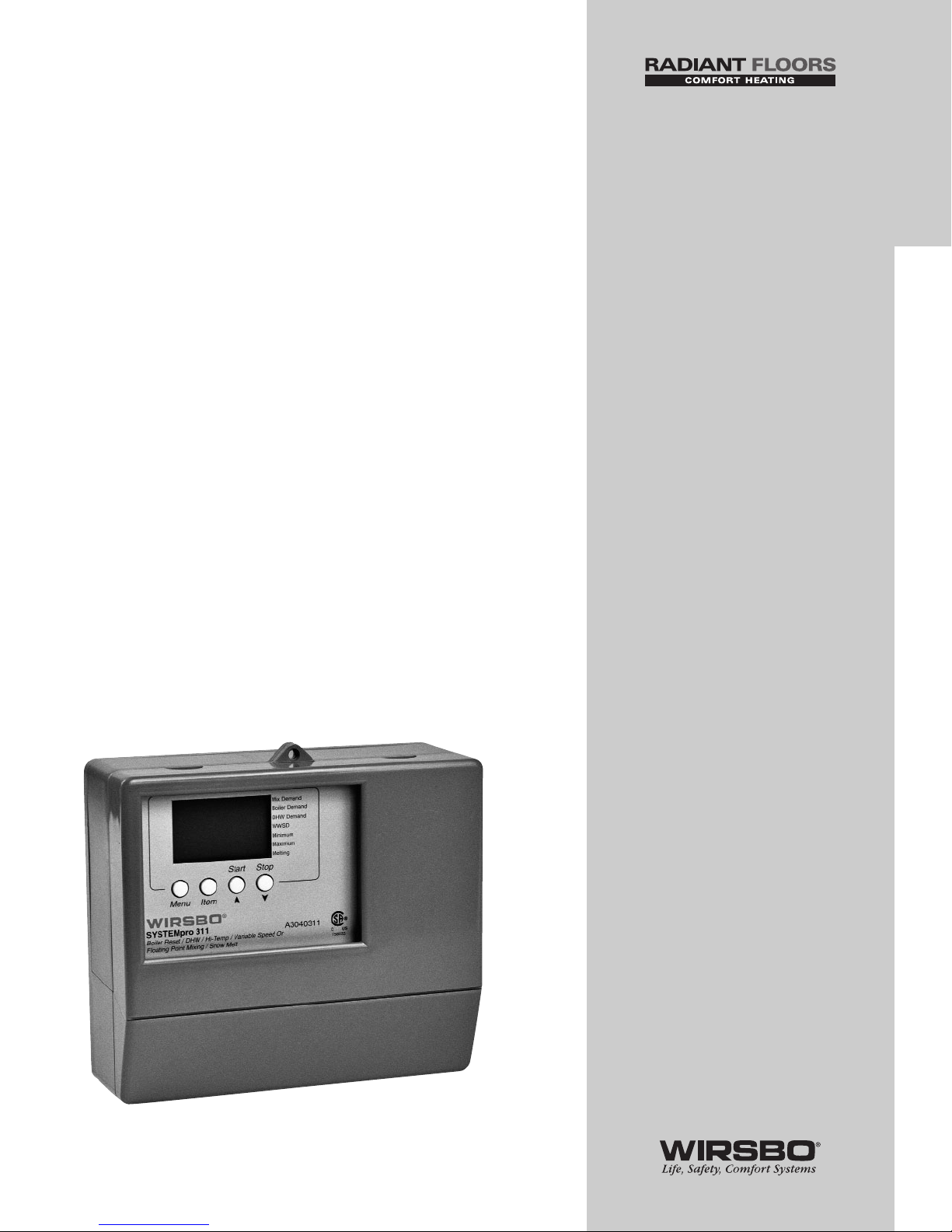
The SYSTEMpro™311 is a multi-temperature reset
control that maximizes the comfort and efficiency of
a hydronic heating system. This weather-responsive
control uses outdoor reset to automatically adjust
boiler and mixed-loop water temperatures supplied
to the heating system. It can be used to supply
mixed-loop water temperature heat to a radiant
floor or snowmelt application and is specifically
created to operate efficiently as part of a Wirsbo
®
radiant/snow melt heating system. For a mixing
device, either a variable speed injection pump or
floating action mixing valve may be used. As an
added benefit, the SYSTEMpro 311 has the ability
to control an indirect Domestic Hot Water (DHW)
storage tank and a semi-automatic snow melt zone.
3
INTRODUCTION
INTRODUCTION - Control Overview
Page 6
INTRODUCTION
NAVIGATING THE CONTROL
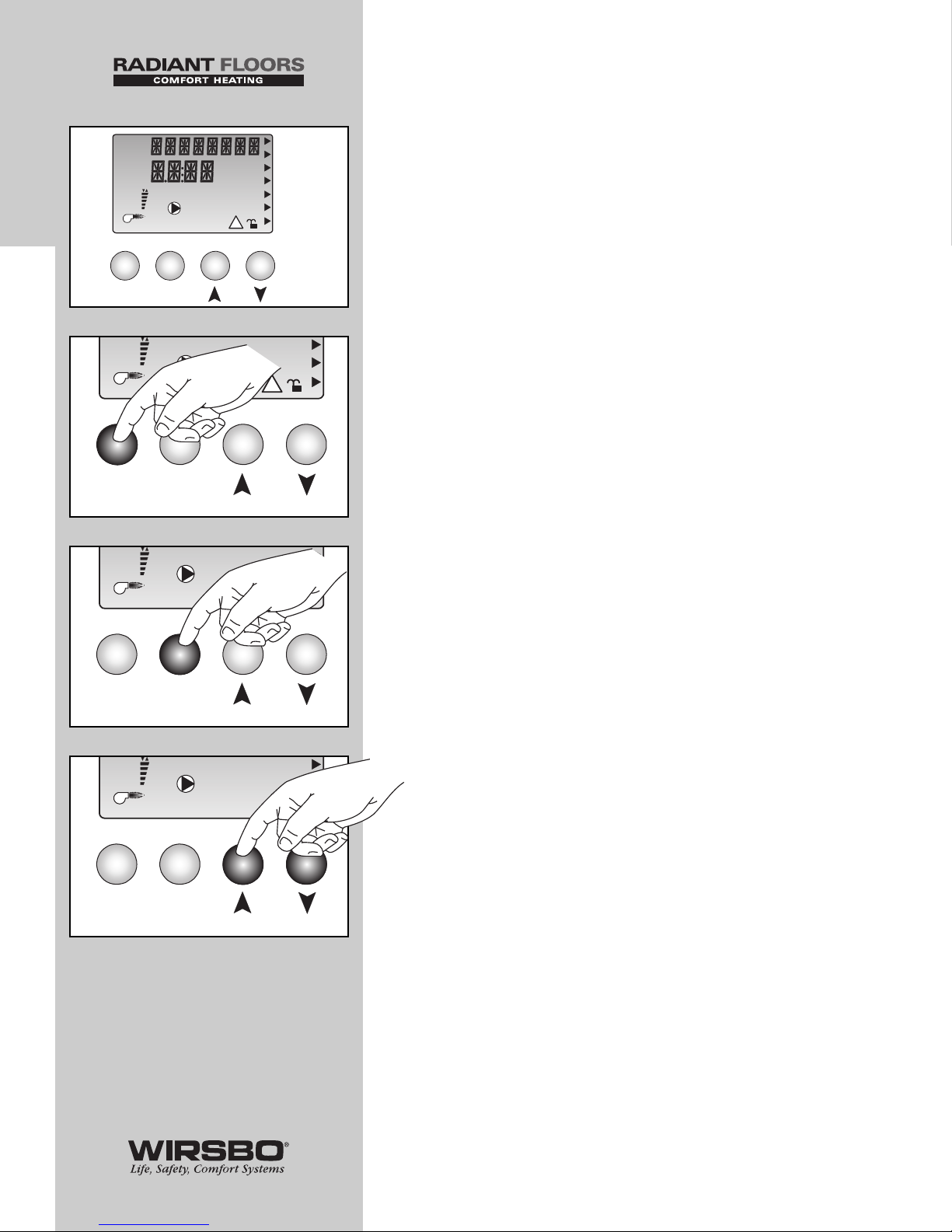
The SYSTEMpro 311 (also referred to as "control") has
a Liquid Crystal Display (LCD) that lets users setup the
operation of the system. The SYSTEMpro 311 has four
push buttons for selecting and adjusting settings.
(See fig. a)
NOTE: It is recommended that the user
record control settings (for later review) on the
Program Setup Sheet provided in Appendix V.
Menu (See fig. b)
• All items displayed by the control are organized into
various menus
• Menus are listed on the left side of the display (Menu Field)
• To select a menu, use the Menu button
• By pressing and releasing the Menu button, the display
will advance to the next available menu
• Within specific menu selections, a group of items can be
viewed and selected
Item (See fig. c)
• The abbreviated name of the selected item will be
displayed in the item field of the display
• To view the next available item, press and release the Item
button
• Once you have reached the last available item in a menu,
press and release the Item button to return the display to
the first item in the same menu
Adjustments (See fig. d)
• To make an adjustment to a control setting, first select the
appropriate menu with the Menu button
• Then select the item you want using the Item button
• Finally, use the up and/or down button to make the change
NOTE: You can get more information by viewing the
Status field of the LCD. The status field shows which
of the control’s outputs are active. Most symbols in
the status field can only be seen when the View
Menu is selected.
4
INTRODUCTION
INTRODUCTION - Navigating the Control
Minimum
Maximum
WWSD
Melting
DHW Demand
Boiler Demand
Mix Demand
Open
Close
Misc
Adjust
min hr
DHW
sec
12
%
!
View
o
o
1
Menu Item
Start Stop
F
C
3
a
Mi
n
Ma
Me
Open
Close
DHW
12
%
!
1
Menu Item
Start Stop
3
b
Mi
n
Ma
Me
Open
Close
DHW
12
%
!
1
Menu Item
Start Stop
3
c
Mi
n
Ma
Me
Open
Close
DHW
12
%
!
1
Menu Item
Start Stop
3
d
Page 7
5
INTRODUCTION
INTRODUCTION - Navigating the Control
Minimum
Maximum
WWSD
Melting
DHW Demand
Boiler Demand
Mix Demand
Open
Close
Misc
Adjust
min hr
DHW
sec
12
%
!
View
o
o
1
Menu Item
Start Stop
F
C
3
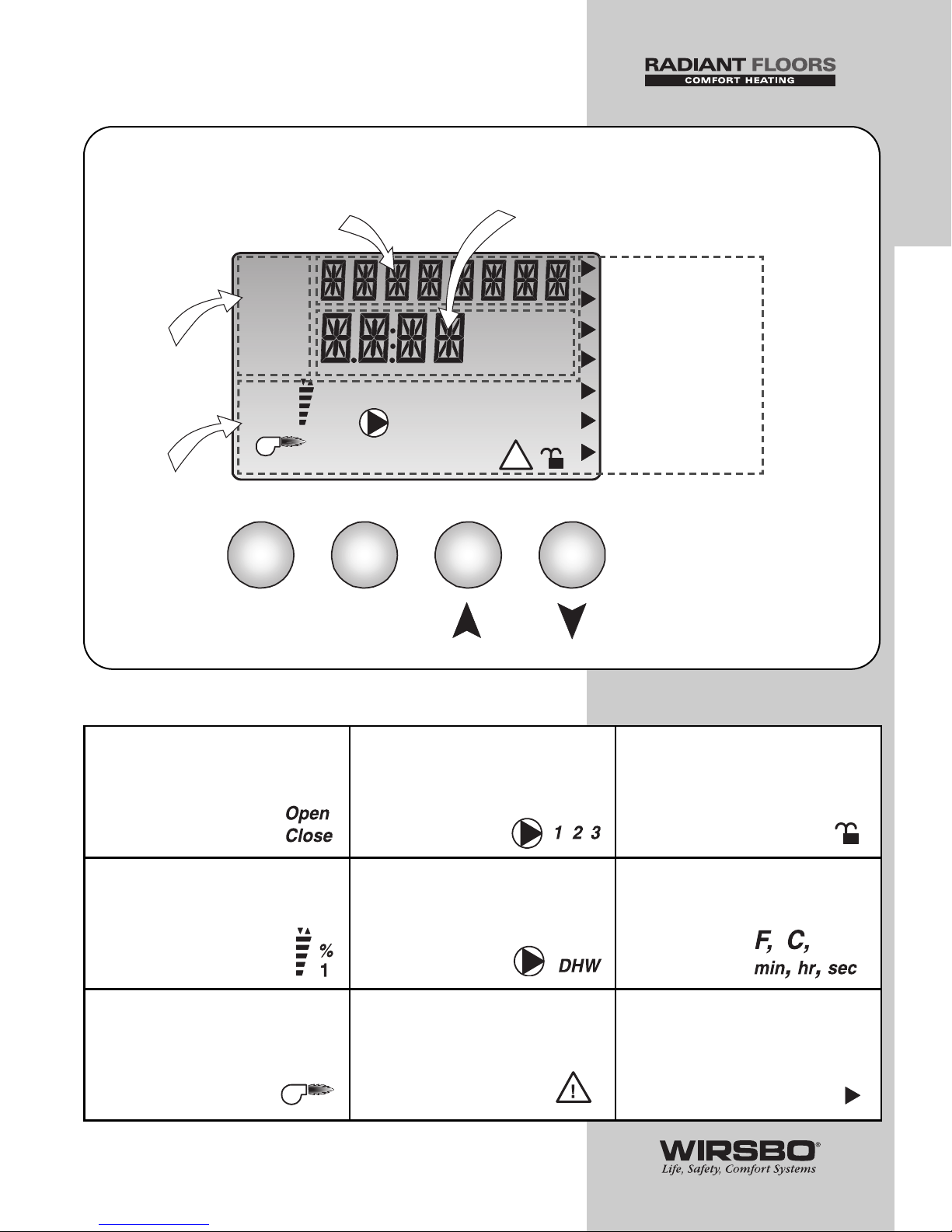
Item Field
Displays an abbreviated
name of the selected item
Menu
Field
Displays the
current menu
Status
Field
Displays the
current status
or the control’s
inputs, outputs
and operation
Buttons
Select menus, items
and adjust settings
Numbers Field
Displays the current value
of the selected item
}
Display
Symbol Description
o
o
Open/Close
Displays when the actuator
is opening or closing.
Mixing Device Output Scale
Shows output of injection
pump or mixing valve. Arrows
show whether the output is
increasing or decreasing.
Burner
Displays when the boiler relay
is turned on.
Pump
Indicates specific pump operation
1 - boiler pump (P3)
2 - boiler demand pump (P7)
3 - mixing pump (P1)
DHW Pump/Valve
Displays when the DHW pump
or valve is on.
Warning
Displays when an error exists or
when a limit has been reached.
Lock/Unlock
Displays when the access levels
are locked or unlocked.
Units of Measurement
Pointer
Displays the control operation
as indicated by the text.
Page 8
Access Levels
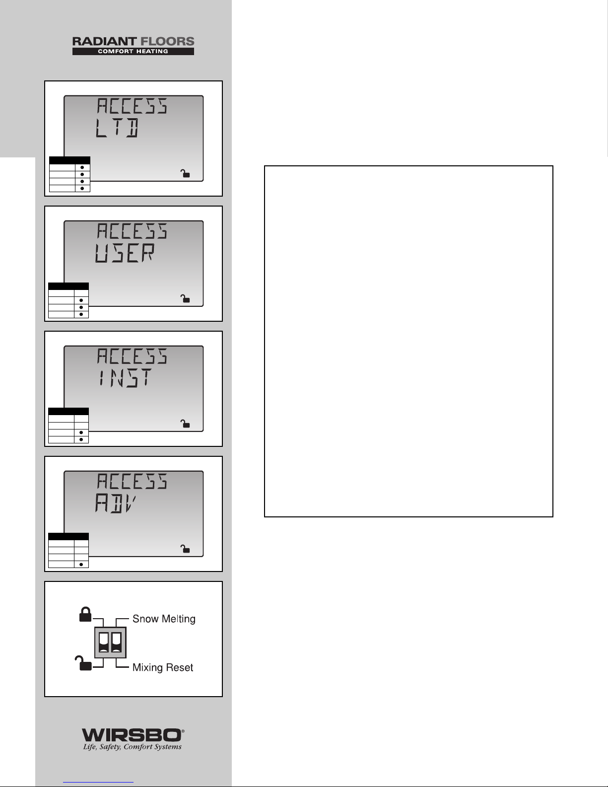
• The SYSTEMpro 311 comes with four Access Level settings
• Access Levels restrict the number of Items and Adjustments
that can be accessed by the user
• The access level of the control is found in the Miscellaneous
(Misc) Menu when the Lock/Unlock DIP switch is set to
the Unlocked position
The four access levels include:
1) Limited (LTD) (See fig. a)
• The most restricted access level
2) User (USER) (See fig. b)
• Allows access to only a few of the items
within a menu
3) Installer (INST) (See fig. c)
• Sufficient for the normal set up of the control
NOTE: This is how the control arrives
from the factory.
4) Advanced (ADV) (See fig. d)
• Allows access to all of the control
settings available
How to Set The Access Level (ACCESS)
(See fig. e)
1) With a small screwdriver, or similar tool - Set the
“Lock/Unlock” DIP switch on control front to Unlock
2) Go to ACCESS item field in MISC Menu
3) Select the level of access that you wish to be used by the
control
RANGE: ADV (Advanced), INST (Installer),
USER (User), LTD (Limited)
DEFAULT: INST (Installer)
6
INTRODUCTION
INTRODUCTION - Navigating the Control
MiscaMiscbMisccMisc
d
Access Level
LTD
USER
INST
ADV
Access Level
LTD
USER
INST
ADV
Access Level
LTD
USER
INST
ADV
Access Level
LTD
USER
INST
ADV
e
Page 9
INTRODUCTION
VIEWING THE STATUS OF
THE SYSTEM PERFORMANCE
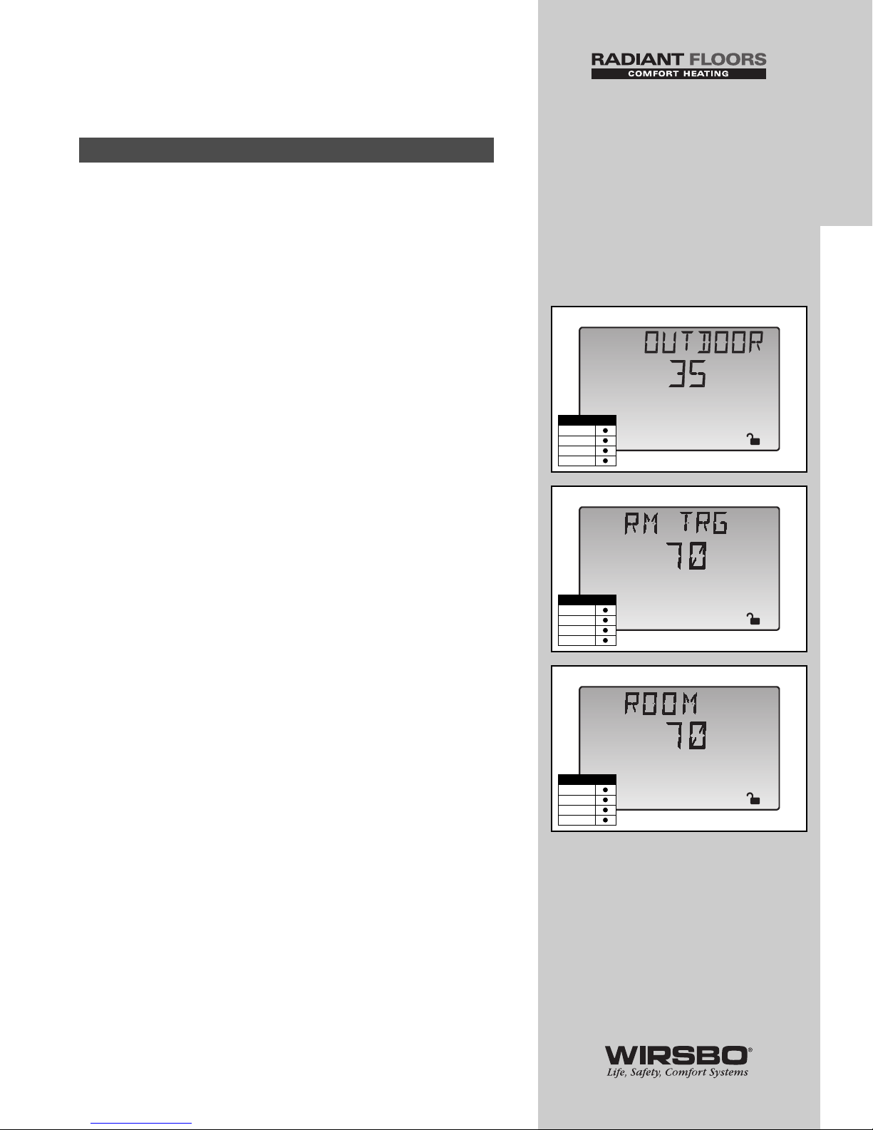
• The View Menu is available for viewing the current status
of the system performance
• By selecting the View Menu, and then pushing the item
button, you can scroll through the available menu items
showing the current settings and temperatures in the system
OUTDOOR (See fig. a)
Shows actual outside temperature at outdoor sensor S4
location
RM TRG (See fig. b)
Targeted room temperature for the mixing zone.
NOTE: This screen will be available in the View Menu
only when the Indoor (INDR) sensor is selected under
the MIX 10K screen in the ADJUST Menu.
ROOM (See fig. c)
Actual room temperature as read by the room sensor
(MIX 10K).
NOTE: This screen will be available in the View Menu
only when the Indoor (INDR) sensor is selected under
the MIX 10K screen in the ADJUST Menu.
Mixing Reset Mode
7
INTRODUCTION
INTRODUCTION - Viewing the Status of the System Performance
%
View
o
F
1
a
Access Level
LTD
USER
INST
ADV
%
View
o
F
1
b
Access Level
LTD
USER
INST
ADV
%
View
o
F
1
c
Access Level
LTD
USER
INST
ADV
Page 10
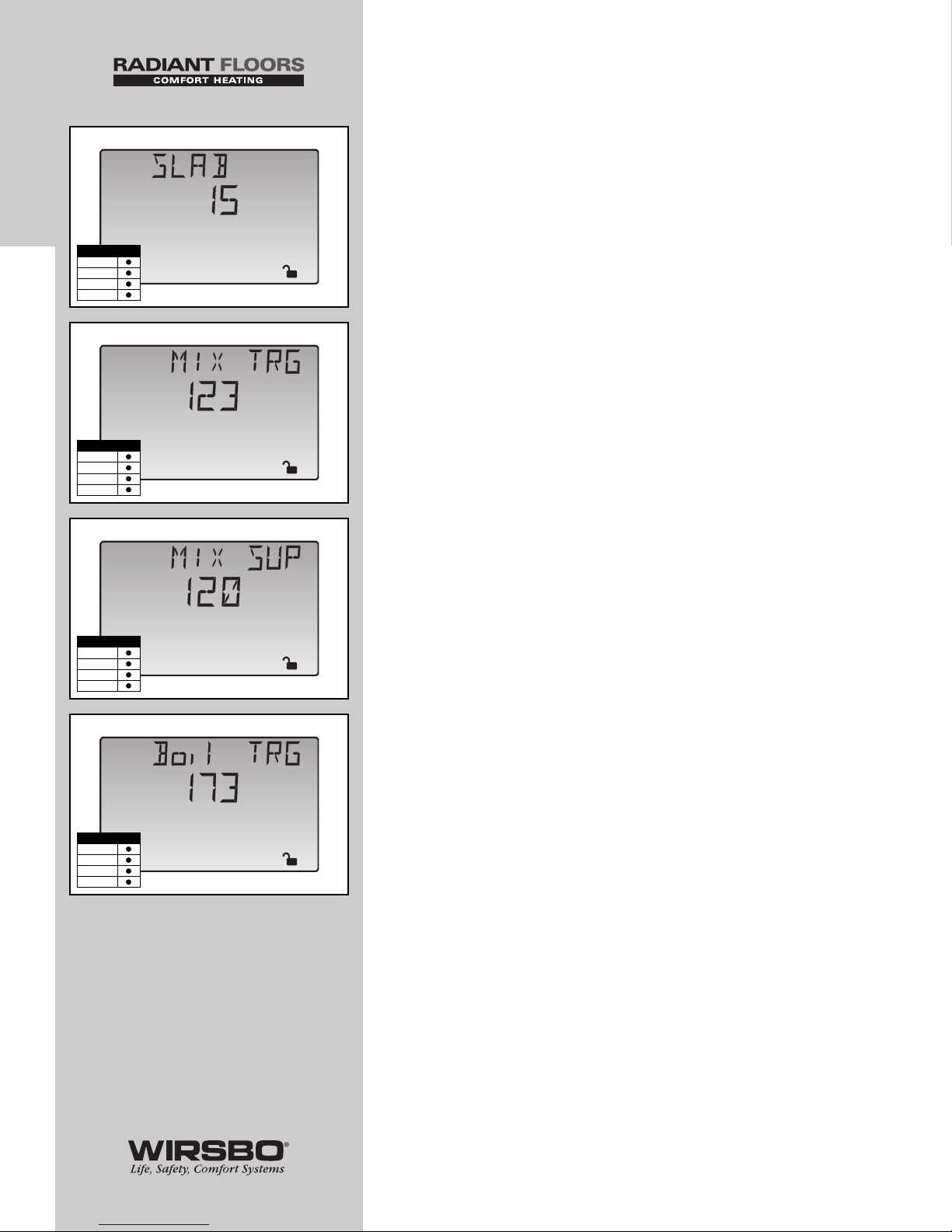
SLAB (See fig. d)
Actual slab temperature as read by the slab sensor S7 (MIX 10K)
NOTE: This screen will be available in the View
Menu only when the Slab (SLAB) sensor is selected
under the MIX 10K screen in the ADJUST Menu.
MIX TRG (See fig. e)
The targeted mixed supply water temperature the control has
calculated in order to meet current conditions
MIX SUP (See fig. f)
Shows actual mix supply water temperature to the system at
mix supply sensor S1 location
Boil TRG (See fig. g)
The targeted boiler supply temperature the control has
calculated in order to meet the current conditions
8
INTRODUCTION
INTRODUCTION - Viewing the Status of the System Performance
%
View
o
F
1
d
Access Level
LTD
USER
INST
ADV
%
View
o
F
1
e
Access Level
LTD
USER
INST
ADV
%
View
o
F
1
f
%
View
o
F
1
g
Access Level
LTD
USER
INST
ADV
Access Level
LTD
USER
INST
ADV
Page 11
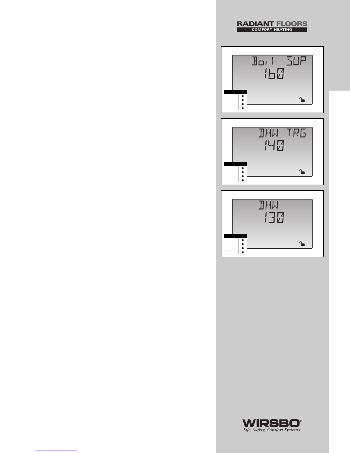
Boil SUP (See fig. h)
Shows actual boiler supply water temperature at boiler supply
sensor S3 location
DHW TRG (See fig. i)
The targeted DHW tank temperature the control has calculated
in order to meet the current DHW demand.
NOTE: This screen will be available in the View
Menu only when a DHW device is selected in
the DHW THRU screen in the ADJUST Menu.
DHW (See fig. j)
Shows the actual DHW tank temperature at the DHW sensor
(S6) location.
NOTE: This screen will be available in the View
Menu only when a DHW device is selected in
the DHW THRU screen in the ADJUST Menu.
9
INTRODUCTION
INTRODUCTION - Viewing the Status of the System Performance
%
View
o
F
1
h
%
View
o
F
1
i
%
View
o
F
1
j
Access Level
LTD
USER
INST
ADV
Access Level
LTD
USER
INST
ADV
Access Level
LTD
USER
INST
ADV
Page 12
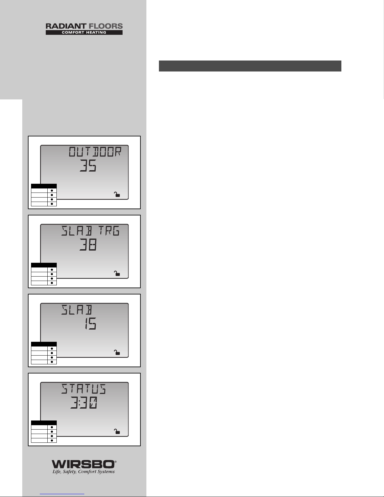
INTRODUCTION
VIEWING THE STATUS OF
THE SYSTEM PERFORMANCE
• The View Menu is available for viewing the current status of
the system performance
• By selecting the View Menu, and then pushing the item
button, you can scroll through the available menu items
showing the current settings and temperatures in the system
OUTDOOR (See fig. a)
Shows actual outside temperature at outdoor sensor S4
location
SLAB TRG (See fig. b)
The targeted temperature the control has calculated in order
to meet current conditions
SLAB (See fig. c)
Shows actual slab temperature at slab sensor S7 location
STATUS (See fig. d)
Shows current snow melt operating status. See Control
Function Overview section page 72 for more detailed
information.
Snow Melt Mode
10
INTRODUCTION
INTRODUCTION - Viewing the Status of the System Performance
%
View
o
F
1
a
%
View
o
F
1
b
%
View
o
F
1
c
%
View
1
hr
d
Access Level
LTD
USER
INST
ADV
Access Level
LTD
USER
INST
ADV
Access Level
LTD
USER
INST
ADV
Access Level
LTD
USER
INST
ADV
Page 13
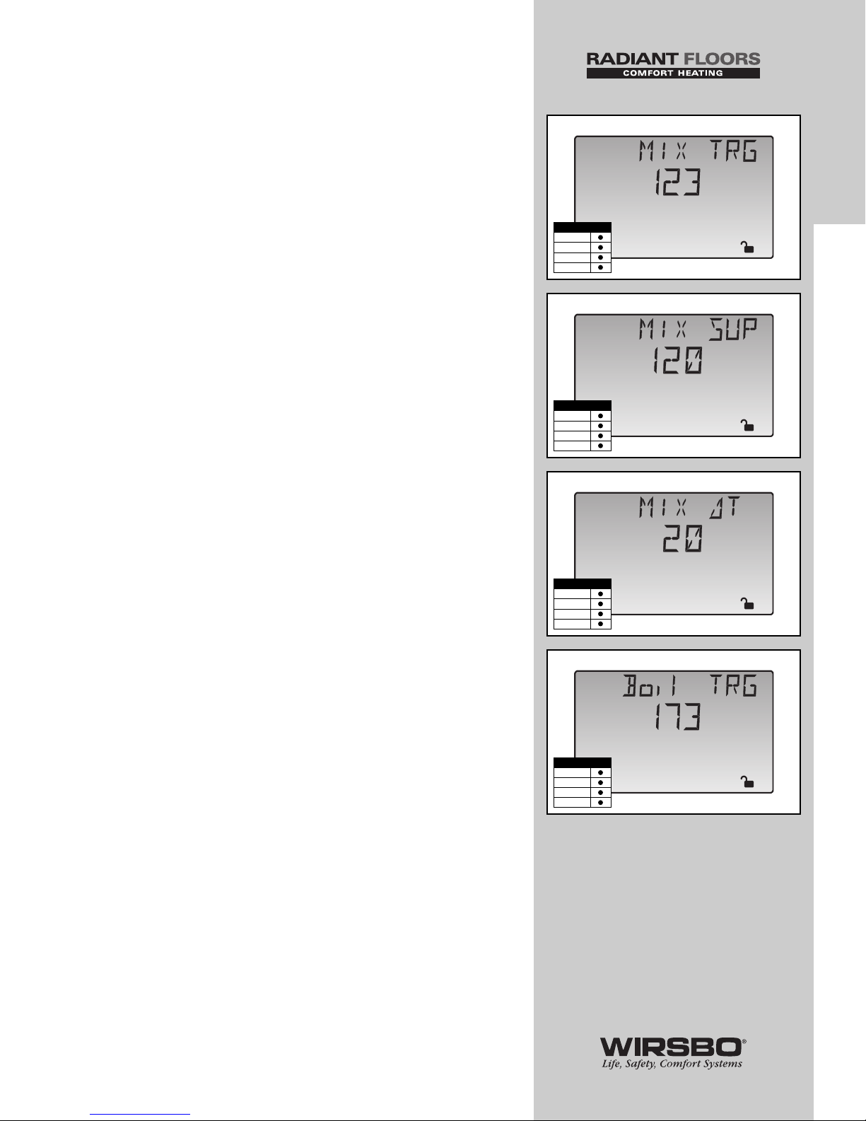
MIX TRG (See fig. e)
The targeted mixed supply water temperature the control has
calculated in order to meet current conditions
MIX SUP (See fig. f)
Shows actual mix supply water temperature to the system at
mix supply sensor S1 location
MIX ∆T (See fig. g)
Shows actual temperature differential (Delta-T) between mix
supply sensor S1 and mix return sensor S5 locations
Boil TRG (See fig. h)
The targeted boiler supply temperature the control has
calculated in order to meet the current conditions
11
INTRODUCTION
INTRODUCTION - Viewing the Status of the System Performance
%
View
o
F
1
e
%
View
o
F
1
f
%
View
o
F
1
g
%
View
o
F
1
h
Access Level
LTD
USER
INST
ADV
Access Level
LTD
USER
INST
ADV
Access Level
LTD
USER
INST
ADV
Access Level
LTD
USER
INST
ADV
Page 14
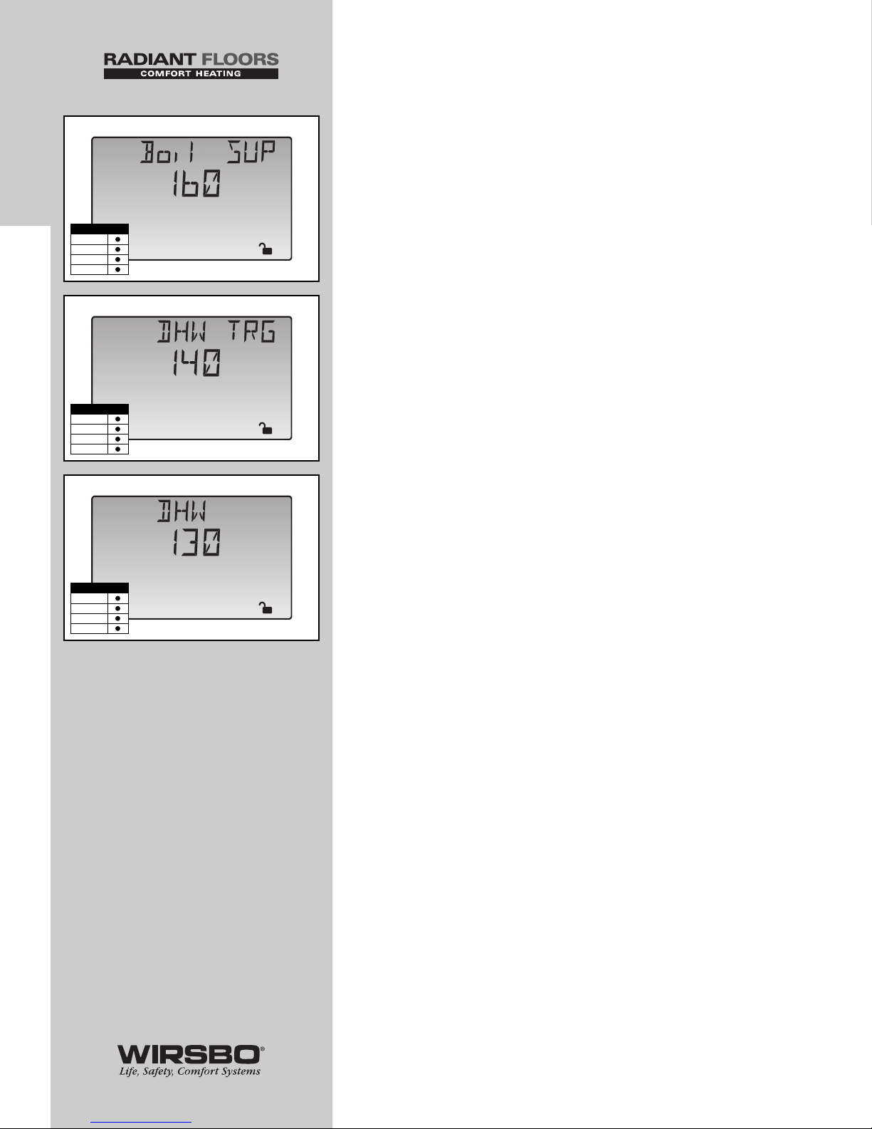
Boil SUP (See fig. i)
Shows actual boiler supply water temperature at boiler supply
sensor S3 location.
DHW TRG (See fig. j)
The targeted DHW tank temperature the control has calculated
in order to meet the current DHW demand. This screen is
available only when a sensor is selected in the DHW SENS
screen in the ADJUST Menu.
DHW (See fig. k)
Shows actual DHW tank temperature at DHW sensor S6
location. This screen is available only when a sensor is
selected in the DHW SENS screen in the ADJUST Menu.
12
INTRODUCTION
INTRODUCTION - Viewing the Status of the System Performance
%
View
o
F
1
i
%
View
o
F
1
j
%
View
o
F
1
k
Access Level
LTD
USER
INST
ADV
Access Level
LTD
USER
INST
ADV
Access Level
LTD
USER
INST
ADV
Page 15

INSTALLATION
TABLE OF CONTENTS
Step 1 – Checking Contents ................................................ 14
Step 2 – The Control Base .............................................. 15-17
Step 3 – Rough-In Wiring...................................................... 18
Step 4 – Attaching the Control to the Base ...................... 19
Step 5 – Mounting the Sensors .................................... 20-22
Step 6 – Electrical Connections to the Control............ 23-28
Powered Input Connection ............................ 23
Output Connections .................................. 24-25
Sensor Connections ........................................ 26
Unpowered Input Connections .................... 27
Temperature Resistance Chart ...................... 28
Step 7 – Testing the Wiring ............................................ 29-32
Test the Sensors .............................................. 29
Test the Power Supply .................................... 30
Test the Powered Demand Inputs ................ 30
Test the Outputs ........................................ 30-32
Step 8 – Completing the Installation .................................. 33
13
INSTALLATION
INSTALLATION - Table of Contents
Page 16
14
INSTALLATION
INSTALLATION - Step 1 - Checking Contents
INSTALLATION - STEP 1
CHECKING CONTENTS
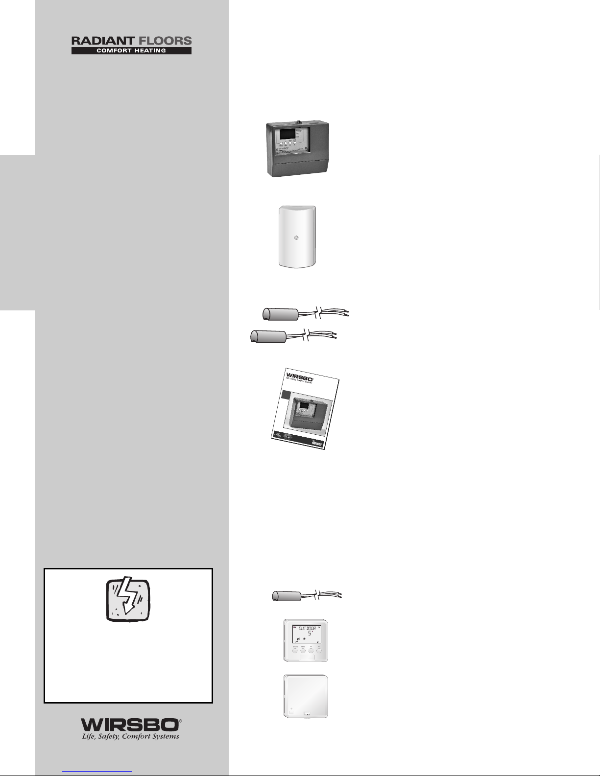
Check the contents of this package.
The Wirsbo SYSTEMpro 311 should have:
One SYSTEMpro 311
(A3040311)
One Outdoor Sensor
(A3040070)
Two Universal Sensors
(A3060071)
One Product Manual
If any of the contents listed are missing or damaged,
please contact your wholesaler or your Wirsbo sales
representative for assistance.
Control Optional Components
(sold separately)
DHW Sensor
(A3060071)
Remote Display
(A3040040)
Snow Melt Enable Kit
(A3040039)
CAUTIONS AND
DISCLAIMERS
Failure to install and/or
operate this control
properly could result in:
• Damage to the
equipment
• Personal injury
• Property damage
It is up to you to make
sure this control is
installed safely in a way
that meets all codes and
standards that apply.
Do not use this electronic
control as a primary limit
control. Other controls
that are meant to be used
and certified to be used
as safety limits must
be placed into the
control circuit.
Carefully read the
Control Overview (page 3)
to make sure you have
chosen the proper control
for your application.
Warning Symbol: Indicates
presence of hazards which
can cause severe personal
injury, death or substantial
property damage if ignored
SYSTEMpro
™
311
Installation Manual
7
9
8
Page 17
INSTALLATION - STEP 2
THE CONTROL BASE
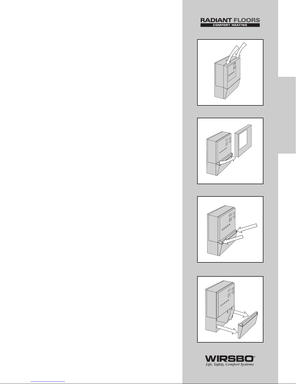
Removing the Control from the Base
Press down at the fingertip grips on top of the
front cover and pull out and down.
(See fig. a)
Lift the front cover up and away from the control.
(See fig. b)
Loosen the screws at the front of the wiring cover.
(See fig. c)
The wiring cover pulls straight out from the wiring
chamber.
(See fig. d)
15
INSTALLATION
INSTALLATION - Step 2 - The Control Base
a
b
c
d
Page 18
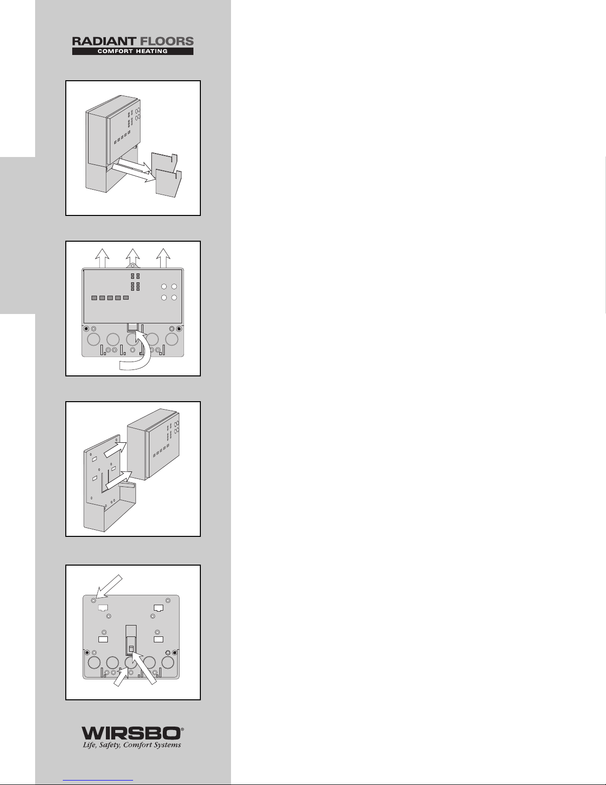
Remove the safety dividers from the wiring chamber by
pulling them straight out of their grooves.
(See fig. e)
Press the control release clip on the base inside the
wiring chamber and slide the control upwards.
(See fig. f)
The control lifts up and away from the base.
(See fig. g)
Mounting the Base (See fig. h)
1) Find a convenient and accessible location typically in
the mechanical room
2) Following the hole pattern, mount the control base
using the appropriate screws
16
INSTALLATION
INSTALLATION - Step 2 - The Control Base
e
f
g
h
Mounting holes
Knockout
Locking Clip
Release Clip
Page 19
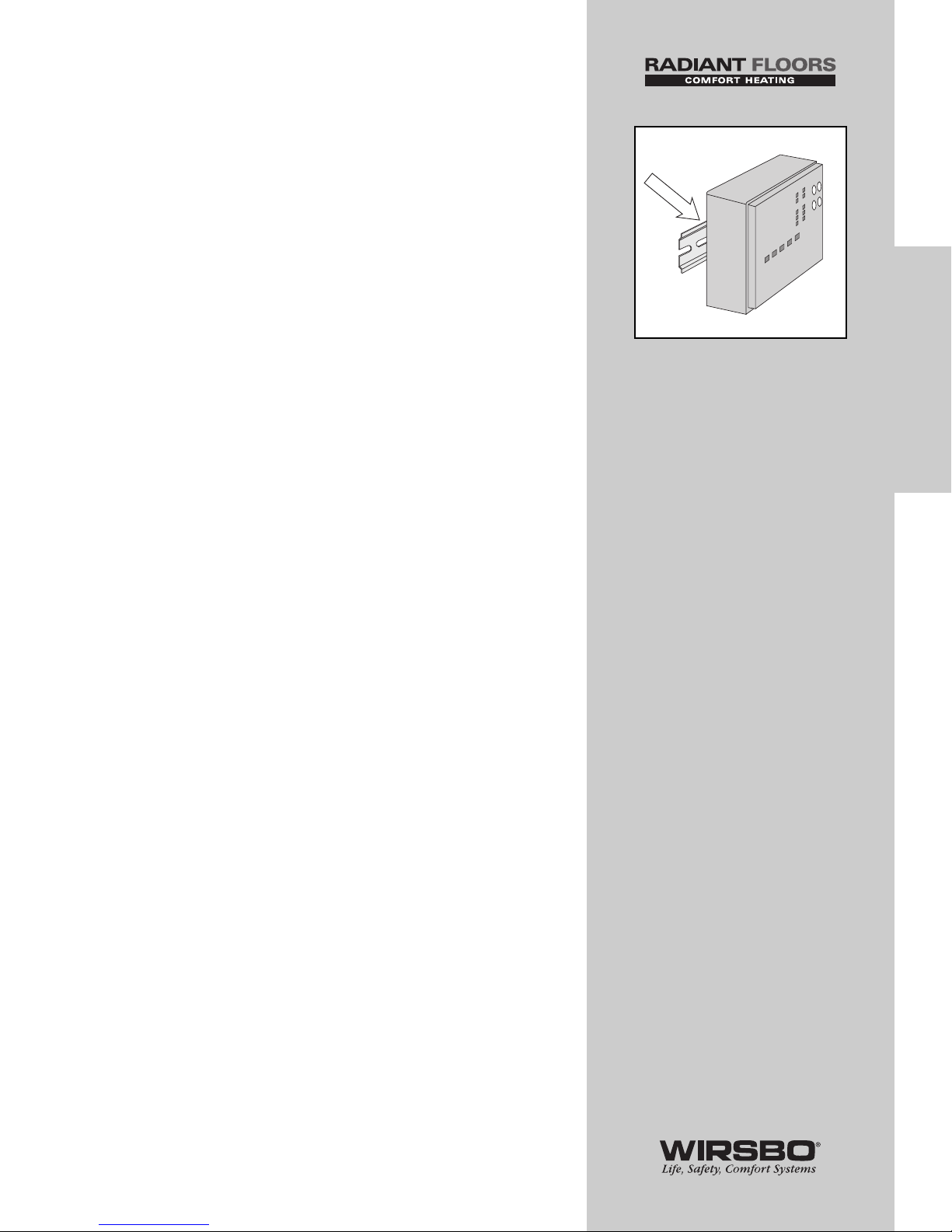
The control can also be mounted on a standard
DIN rail. (See fig. i)
First remove the control from its base and then, using the
hooks and spring clip on the back of the control (ordered
separately), mount it onto the DIN rail. This will be a
popular option for those who prefer to mount the control
inside a larger electrical panel.
The wiring can enter the bottom or the back of the
enclosure. Knock-outs provided in the base allow the
wiring to be run in conduit up to the enclosure. The base
also has holes that line up with the mounting holes of
most common electrical boxes.
17
INSTALLATION
INSTALLATION - Step 2 - The Control Base
i
Page 20

INSTALLATION - STEP 3
ROUGH-IN WIRING
Things to note before you start wiring:
• All electrical wiring should end in the control base wiring
chamber
• The base has standard 7/8” (22 mm) knockouts
• Knockouts accept common wiring hardware and conduit
fittings
• Before removing knockouts, check wiring diagram and
select those sections of the chamber with common
voltages
• Do not allow the wiring to cross between low/high voltage
sections or else wires will interfere with safety dividers
(these dividers should be installed at a later time)
• Do not apply power to any of the wires during rough-in
wiring stage
• All wires should be stripped to 3/8"L (9 mm) for the correct
connection to the control
Wiring Components:
1) Install the various sensors indicated below as per instructions
listed and run the wiring back to the control base and label all
wires for later installation
Main Sensors:
• Outdoor Sensor S4
• Boiler Sensor S3
• Mixing Sensor S1
Optional Sensors:
• DHW Sensor S6
• Mixing Return Sensor S5
• Slab Sensor S7
Optional Modules:
• Remote Display Module (RDM)
• Snow Melt Enable Kit
2) Run appropriate wire from all other system components
(pump, boiler, etc.) to the control base
3) Run wires from the 120 VAC power to the control base
• Use a clean power source to ensure proper operation
• Comply with local codes for minimum gauge and breaker
requirements
18
INSTALLATION
INSTALLATION - Step 3 - Rough-In Wiring
CAUTION
All wiring must be
performed by a licensed
professional and comply
with local trade practices
and codes.
Wirsbo does not take
responsibility for any
damage caused due to
failure to comply.
Page 21
INSTALLATION - STEP 4
ATTACHING THE CONTROL
TO THE BASE
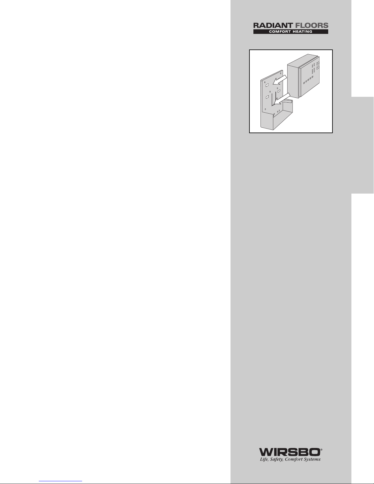
1) Push the SYSTEMpro 311 control into the base you
mounted in Step 2
2) Slide the control down until it snaps firmly into place
(See fig. a)
19
INSTALLATION
INSTALLATION - Step 4 - Attaching the Control to the Base
a
Page 22
INSTALLATION - STEP 5
MOUNTING THE SENSORS
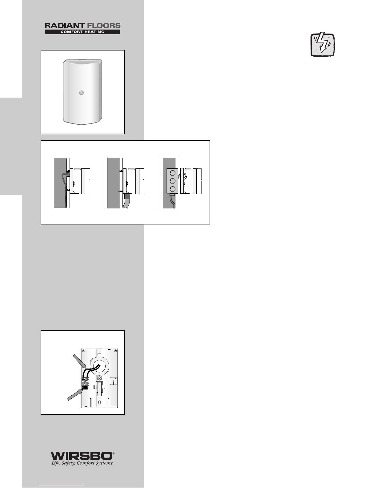
Outdoor Sensor (S4)
(See fig. a)
The Outdoor Sensor includes a 10 kΩ thermistor which
provides an accurate measurement of the outdoor
temperature. The sensor is protected by a white U.V.
resistant PVC plastic enclosure.
Step One – Mounting (See fig. b)
NOTE: The temperature sensor (thermistor)
is built into the enclosure.
• Remove the screw and pull the front
cover off the sensor enclosure.
• The outdoor sensor can either be
mounted directly onto a wall or a 2" x 4"
electrical box. When the sensor is wall
mounted, the wiring should enter
through the back or bottom of the
enclosure. Do not mount the sensor with
the conduit knockout facing upwards as
rain could enter the enclosure and
damage the sensor.
• In order to prevent heat transmitted through the wall from
affecting the sensor reading, it may be necessary to install an
insulating barrier behind the enclosure.
• The outdoor sensor should be mounted on an exterior wall
which best represents actual outdoor temperature (a north
facing wall). It should not be exposed to heat sources such
as solar gain, exhaust ventilation or window openings.
• The outdoor sensor should be installed at an elevation
above the ground that will prevent accidental damage or
tampering. Installing the sensor in the shadow of the roof
eave is common.
Step Two – Wiring and Testing (See fig. c)
• Connect 18 AWG or similar wire to the two terminals provided
in the enclosure and run the wires from the outdoor sensor to
the control.
CAUTION: Do not run sensor wires parallel to
telephone or power cables. If the sensor wires
are located in an area with strong sources of
electromagnetic interference (EMI), shielded cable or
twisted pair should be used or the wires can be run
in a grounded metal conduit. If using shielded cable,
the shield wire should be connected to the Com Sen
terminal on the control and not to earth ground.
• Follow the sensor testing instructions in this brochure and
connect the wires to the control as per installation – step 6.
• Replace the front cover of the sensor enclosure.
20
INSTALLATION
INSTALLATION - Step 5 - Mounting the Sensors
Wires from outdoor
sensor to control terminals
(Com Sen - Out Sen)
Sensor is built into
the enclosure
c
Sensor with rear
entry wiring
Sensor
with bottom
entry wiring
Sensor mounted
onto 2” x 4”
electrical box
a
b
Page 23
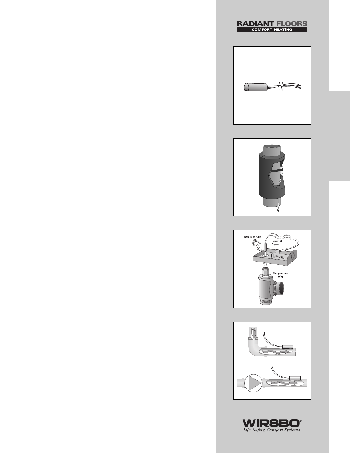
Universal Sensors (S1, S3, S5 & S6)
(See fig. d)
These Universal Sensors have a zinc sleeve for fast response
and a wide operating range. They can be used in a multitude
of applications. They are supplied with 10 inches (250 mm) of
2 conductor wire.
Step One – Mounting (See figs. e thru g)
NOTE: The Sensor is designed to mount on
a pipe or in a temperature immersion well.
• The Universal Sensor can be strapped directly to the pipe
using the cable tie provided. Insulation should be placed
around the sensor to reduce the effect of air currents on the
sensor measurement.
• The Universal Sensor should be placed downstream of
a pump or after an elbow or similar fitting. Proper sensor
location requires that the fluid is thoroughly mixed within the
pipe before it reaches the sensor.
Step Two – Wiring and Testing
CAUTION: Do not run sensor wires parallel to
telephone or power cables. If the sensor wires
are located in an area with strong sources of
electromagnetic interference (EMI), shielded cable or
twisted pair should be used or the wires can be run
in a grounded metal conduit. If using shielded cable,
the shield wire should be connected to the Com Sen
terminal on the control and not to earth ground.
• If it is necessary to connect 18 AWG wire to the two sensor
wires, wire nuts can be used to hold the wires together.
• Follow the sensor testing instructions given in this brochure
and then connect the wires to the control.
21
INSTALLATION
INSTALLATION - Step 5 - Mounting the Sensors
e
f
d
g
Page 24
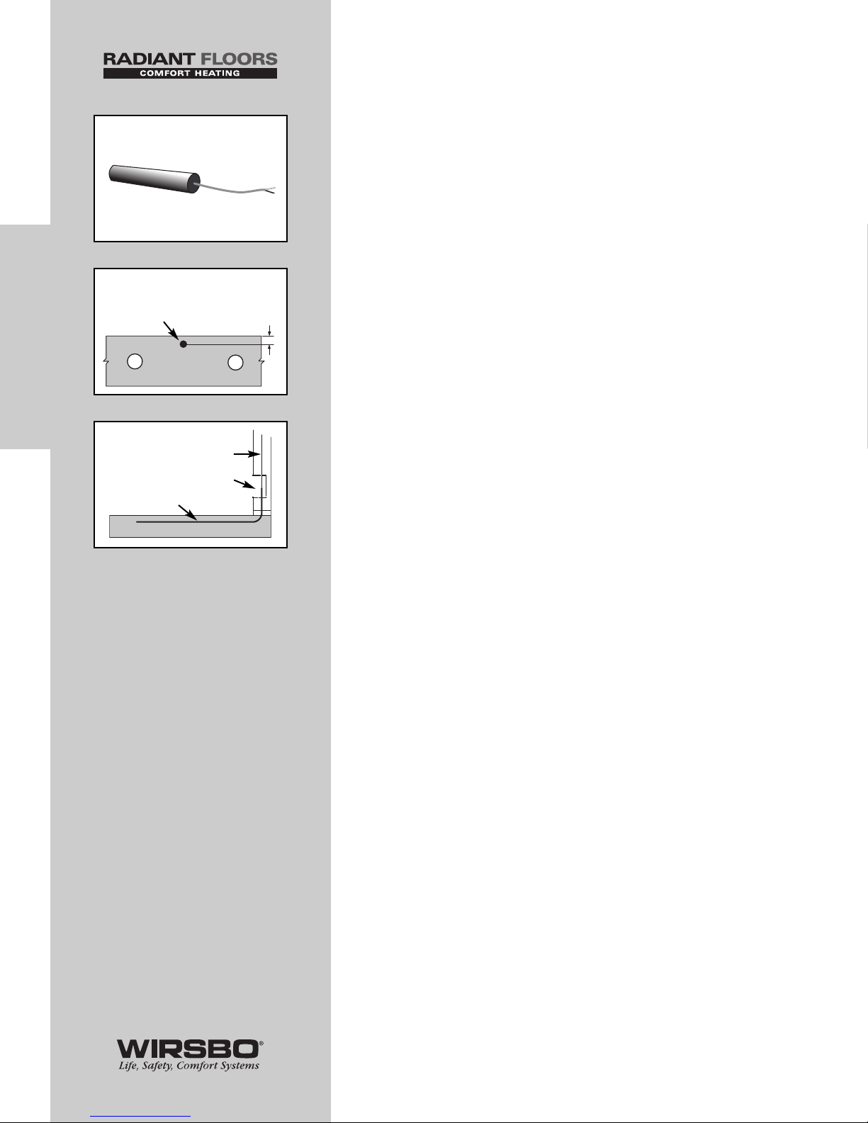
Slab Sensor (S7) (See fig. h)
The Slab Sensor has a PVC plastic sleeve which is designed
for use in soils or concrete. It is supplied with 20 ft (6 m) of 2
conductor cable.
Step One – Mounting (See fig. i)
NOTE: Proper placement of this sensor is
critical for correct operation of the control.
This sensor is designed to be embedded in the slab material.
It is highly recommended the sensor be installed in a plastic
or metal conduit embedded in the slab. If there is ever a
sensor failure, this allows the sensor to be removed and
replaced. The sensor should be placed 1” (25 mm) below the
slab surface and half way between the pipes. Access to the
conduit after leaving the slab should be available for replacing
the sensor in the future if required.
(See fig. j)
Step Two – Wiring and testing
CAUTION: Do not run sensor wires parallel to
telephone or power cables. If the sensor wires
are located in an area with strong sources of
electromagnetic interference, shielded cable
or twisted pair should be used or the wires can
be run in a grounded metal conduit. The ground
wire should be connected to the common sensor
terminal on the control and not to earth ground.
The Slab Sensor is supplied with 20' (6 m) of cable. If a longer
length is required, 18 AWG wire can be spliced onto the two
wires from the sensor. The splices should be properly
soldered and protected in an accessible, waterproof junction
box. Follow the sensor testing instructions given in this
brochure and then connect the wires to the control.
22
INSTALLATION
INSTALLATION - Step 5 - Mounting the Sensors
h
i
Sensor half
way between
the pipes/cables
1”
(25 mm)
j
Conduit w/sensor
Sensor wire
Access panel
Page 25
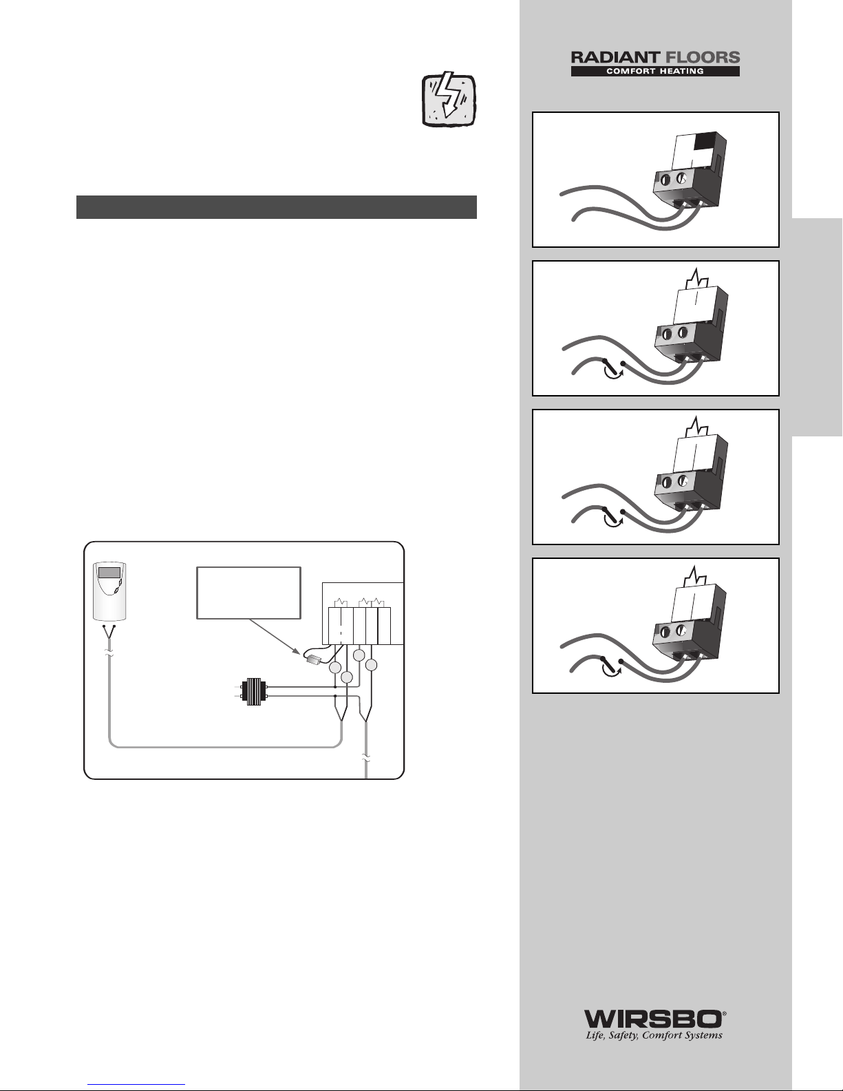
INSTALLATION - STEP 6
ELECTRICAL CONNECTIONS
TO THE CONTROL
IMPORTANT: Test to be certain
no voltage is present in any wires.
120 VAC Power (See fig. a)
• Provides power to microprocessor and control display as well
as power to Boil P3 terminal (8) from Power L terminal (7)
• Connect 120 VAC power supply to Power L and Power N
terminals (6 and 7)
Demand Connections
Demand to the control is generated from a thermostat zone
control module or external relay. This connection must have
24 VAC supplied to the demand terminals
Mixing Demand (See fig. b)
• Apply a voltage between 24 VAC and 240 VAC across Mixing
Demand terminals (1 and 2)
Mixing Demand with Wirsbo Thermostat
NOTE: When connecting a Wirsbo Thermostat WT1
or WT2 directly to the Mix Demand Terminals 1 and 2,
a 0.5 watt 1000 ohm resistor needs to be installed
parallel as shown. A packet with the resistor and
schematic is included in the box.
Boiler Demand (See fig. c)
• Apply a voltage between 24 VAC and 240 VAC across
Boil Dem and Com Dem terminals (3 and 4)
DHW Demand (See fig. d)
• Apply a voltage between 24 VAC and 240 VAC across DHW
and the Com Dem terminals (4 and 5)
Powered Input Connections
23
INSTALLATION
INSTALLATION - Step 6 - Electrical Connections to the Control
N
6
L
7
120 VAC
Power
Mix
Demand
1
2
24 to 240 VAC
Boil
Dem
3
Com
Dem
4
24 to 240 VAC
Com
Dem
4
DHW
Dem
5
24 to 240 VAC
b
a
c
d
1
24 VAC
TRANSFORMER
120 VAC
L
N
2
3
4
WIRSBO
RH W
NOTE:
0.5w 1000 Ohm
Resistor
54321
Mix
Demand
Boil Com DHW
Dem
Dem
Dem
WIRSBO
THERMOSTAT
WT 1
(A3030101)
or
WT 2
(A3030102)
Page 26
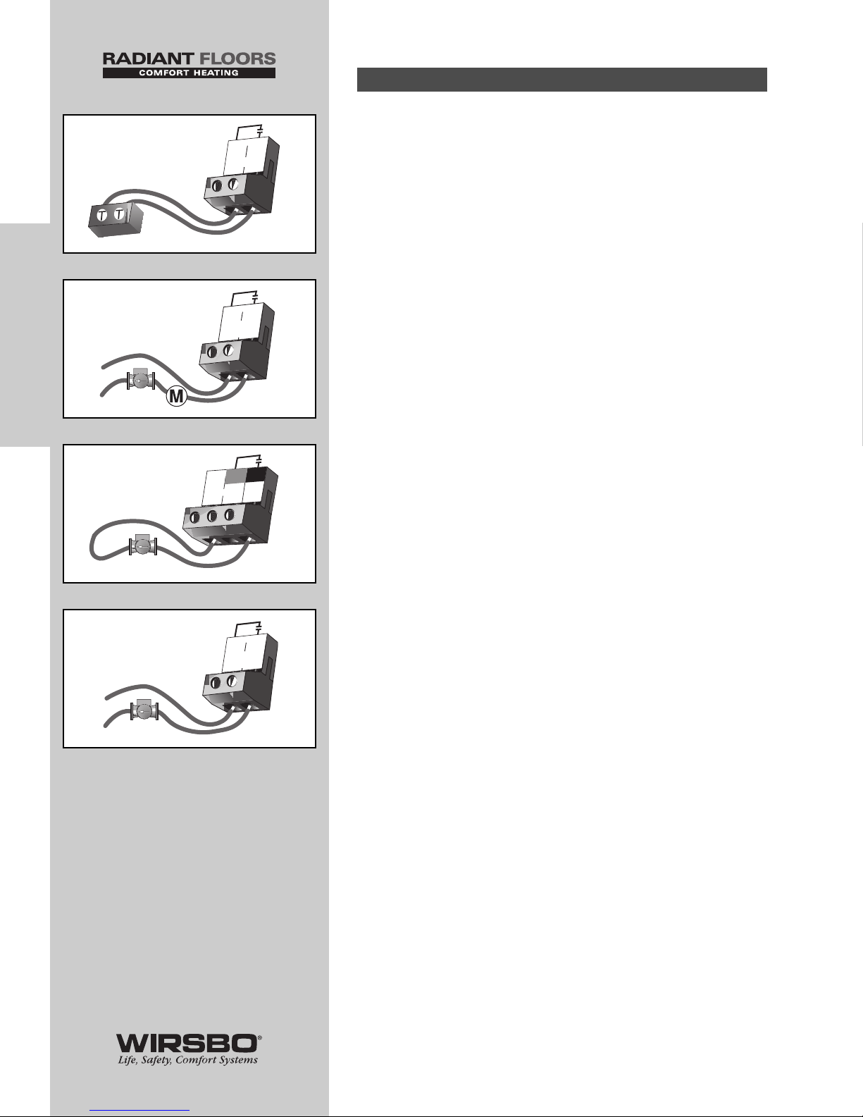
1) Boiler Contact (See fig. e)
Boiler terminals (15 and 16) are an isolated output. No power
is available on these terminals from the control.
• Use terminals as switch to make or break the boiler circuit
• When the SYSTEMpro 311 requires the boiler to fire, contact
closes between terminals 15 and 16
2) DHW Pump/Valve Contact (See fig. f)
DHW P6/Vlv terminals (13 and 14) are an isolated
output. No power is available on these terminals from the
control.
• Use terminals as switch to either make or break power to
DHW pump or valve
• As an isolated contact it may switch a voltage between 24
VAC and 240 VAC
3) Primary Pump Contact (Boil P3) (See fig. g)
Boil P3 output terminal (8) is a powered output. When relay in
the SystemPro 311 closes, 120 VAC is provided to Boil P3
terminal (8) from Power L terminal (7).
• To operate primary pump, connect one side of primary pump
circuit to terminal (8) and second side of pump circuit to
neutral N terminal (6) side of 120 VAC power supply
4) Boiler Demand Pump (Boil Dem Pmp P7)
(See fig. h)
Boil Dem Pmp P7 terminals (9 and 10) are an isolated output.
No power is available on these terminals from the control.
• Use terminals as a switch to make or break power to the
boiler system pump
• As an isolated contact, it may switch a voltage between
24 VAC and 240 VAC
Output Connections (1-7)
24
INSTALLATION
INSTALLATION - Step 6 - Electrical Connections to the Control
6
L
Boil
P3
Pow
er
120 VAC
8
N
7
Boil Dem
Pmp P7
9
10
120 VAC
L
N
g
h
Boiler
15
16
DHW
P6/Vlv
13
14
24 to 240 VAC
or
e
f
Page 27
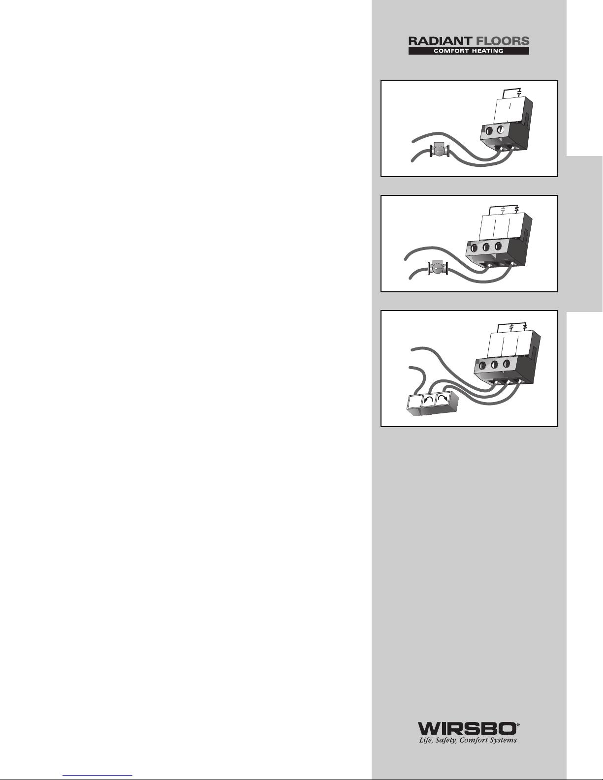
5) Mixing System Pump (Mixing Pmp P1)
(See fig. i)
Mixing Pmp P1 terminals (11 and 12) are isolated outputs.
No power is available on these terminals from the control.
• Use terminals as a switch to either make or break power
to mixing system pump
• As an isolated contact, it may switch a voltage between
24 VAC and 240 VAC
6) Variable Speed Injection Pump (Cls/P4)
(See fig. j)
The SYSTEMpro 311 can vary the speed of a pump motor with
locked rotor current of less than 2.4 A (most small wet rotor
circulators may be used as described in APPENDIX I - page 85).
• If using a variable speed injection pump, connect one of
the wires from variable speed injection pump to Cls/P4
terminal (19)
• Connect other wire on variable speed injection pump to live
(L) side of 120 VAC power supply
• Connect Pwr Mix terminal (17) to neutral (N) side of 120 VAC
power source
7) Mixing Valve Actuator (See fig. k)
If a mixing valve is used:
• Connect one side of 24 VAC power to Pwr Mix terminal (17)
on control
• Connect output relay Opn (18) to the "open" terminal of
actuating motor
• Connect output relay Cls/P4 (19) to the "close" terminal of
actuating motor
• Connect second side of 24 VAC circuit to common terminal
of actuating motor
NOTE: The SYSTEMpro 311 has an internal
overload fuse rated at 2.5 A 250 VAC — contact
your Wirsbo sales representative for repair
information if fuse is blown.
25
INSTALLATION
INSTALLATION - Step 6 - Electrical Connections to the Control
Mixing
Pmp P1
11
12
120 VAC
L
N
i
120 VAC
L
N
Pw
r
17
Mix
Opn
18
Cls/
19
P4
j
Pw
r
17
Mix
Opn
18
Cls/
19
P4
24 or 1
20 VAC
R
C
Com
k
Page 28
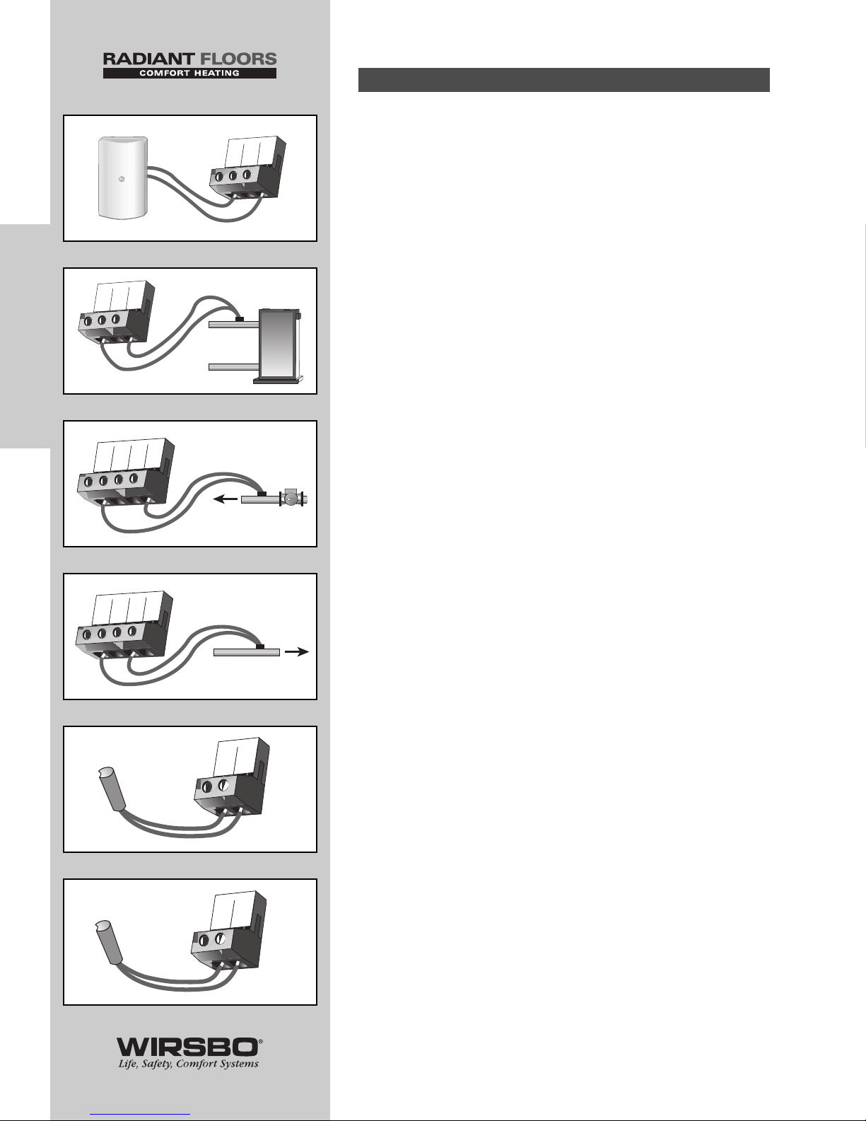
WARNING: Do not apply power to these
terminals as this will damage the control.
Connect the two wires from sensors to terminals described
below:
8) Outdoor Sensor S4 wires to Com
and Out terminals (27 and 29) (See fig. l)
• Measures outdoor air temperature
9) Boiler Sensor S3 wires to Com
and Boil S3 terminals (24 and 26) (See fig. m)
• Measures supply water temp from boiler
10) Mixing Supply Sensor S1 wires to Com
and Mix S1 terminals (20 and 23) (See fig. n)
• Measures the supply temperature after the mixing device
NOTE: Sensor is normally attached downstream
of mixing system pump (P1).
11) Mixing Return Sensor S5 wire to Com
and Ret S5 terminals (20 and 22) (See fig. o)
• Measures fluid return temperature from snow melting slab
NOTE: This sensor is only used when the
Snow Melting/Mixing Reset DIP switch is
set to the Snow Melting position
12) Mix 10K Sensor to Com and Mix 10K
terminals (20 and 21) (See fig. p)
• Works with indoor sensor, slab sensor, or zone control
sensor
13) DHW Sensor S6 to Com and DHW S6
terminals (27 and 28) (See fig. q)
• Measures temperature in DHW (Domestic Hot Water) tank
Sensor Connections (8-13)
26
INSTALLATION
INSTALLATION - Step 6 - Electrical Connections to the Control
Com
27
28
DHW
S6
q
Com
20
21
Mix
10K
p
Com
27
DHW
S6
28
Out
29
S4
l
Com
24
Boil
Zo in
25
Boil
26
S3
Boiler
Sensor
m
Com
20
Mix
10K
21
Ret
22
S5
Mix
23
S1
n
Com
20
Mix
10K
21
Ret
22
S5
Mix
23
S1
o
Page 29
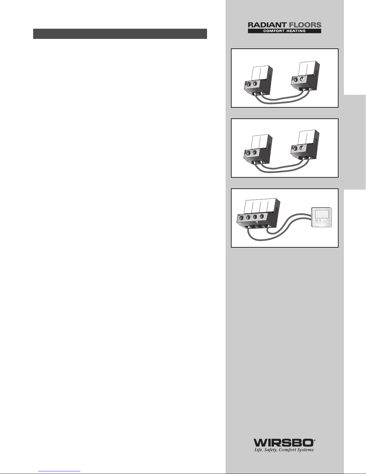
WARNING: Wires from unpowered input connections
are polarity sensitive. The communication of these
devices will not operate correctly if the wires
are reversed.
14) Mixing Zone Control Input (See fig. r)
An external tekmar zone control may be used to control
mixing zones.
• Connect wire from Com Sen terminal on zone control to
Com terminal (20) on SYSTEMpro 311
• Connect ZoOut terminal on zone control to Mix 10K terminal
(21) on SYSTEMpro 311
15) Boiler Zone Control Input (See fig. s)
An external tekmar zone control may be used to control boiler
zones.
• Connect wire from Com Sen terminal on zone control to
Com terminal (24) on the SYSTEMpro 311
• Connect the ZoOut terminal on zone control to Boil ZoIn
terminal (25) on the SYSTEMpro 311
16) tN2 Device (See fig. t)
A Remote Display Module or Snow Melt Enable may be
connected to the tN2 input on the SYSTEMpro 311.
• Connect the Com terminal from Remote Display Module or
Snow Melt Enable to Com terminal (27) on SYSTEMpro 311
• Connect the tN2 terminal from Remote Display Module or
Snow Melt Enable to the tN2 terminal (30) on SYSTEMpro 311
Unpowered Input Connections (14-16)
27
INSTALLATION
INSTALLATION - Step 6 - Electrical Connections to the Control
Zo
Out
Com
Sen
Com
20
21
Mix
10K
SYSTEMpro 311
Zone Control
r
Zo
Out
Com
Sen
Com
24
25
Boil
Zo in
SYSTEMpro 311
Zone Control
s
Com
27
DHW
S6
28
Out
29
S4
tN2
30
t
Page 30
28
INSTALLATION
INSTALLATION - Step 6 - Electrical Connections to the Control
ΩΩΩΩ
20
25
30
35
40
45
50
55
60
65
70
75
80
85
90
95
100
105
110
115
120
125
130
135
140
145
150
155
160
165
170
175
180
185
190
195
200
205
210
215
220
225
-7
-4
-1
2
4
7
10
13
16
18
21
24
27
29
32
35
38
41
43
46
49
52
54
57
60
63
66
68
71
74
77
79
82
85
88
91
93
96
99
102
104
107
490,813
405,710
336,606
280,279
234,196
196,358
165,180
139,402
118,018
100,221
85,362
72,918
62,465
53,658
46,218
39,913
34,558
29,996
26,099
22,763
19,900
17,436
15,311
13,474
11,883
10,501
9,299
8,250
7,334
6,532
5,828
5,210
4,665
4,184
3,760
3,383
3,050
2,754
2,490
2,255
2,045
1,857
1,689
1,538
1,403
1,281
1,172
1,073
983
903
829
763
703
648
598
553
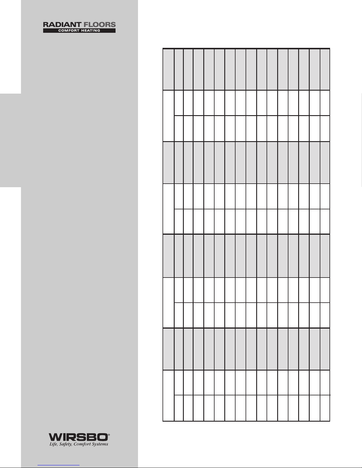
Temperature Resistance Temperature Resistance Temperature Resistance Temperature Resistance
°F °C °F °C °F °C °F °C
-50
-45
-40
-35
-30
-25
-20
-15
-10
-5
0
5
10
15
-46
-43
-40
-37
-34
-32
-29
-26
-23
-21
-18
-15
-12
-9
Temperature Resistance Chart
Page 31
INSTALLATION - STEP 7
TESTING THE WIRING
NOTE: The following tests are to be performed
using standard testing practices and procedures.
They should only be carried out by properly
trained and experienced installers.
Things to note
before you start ANY testing:
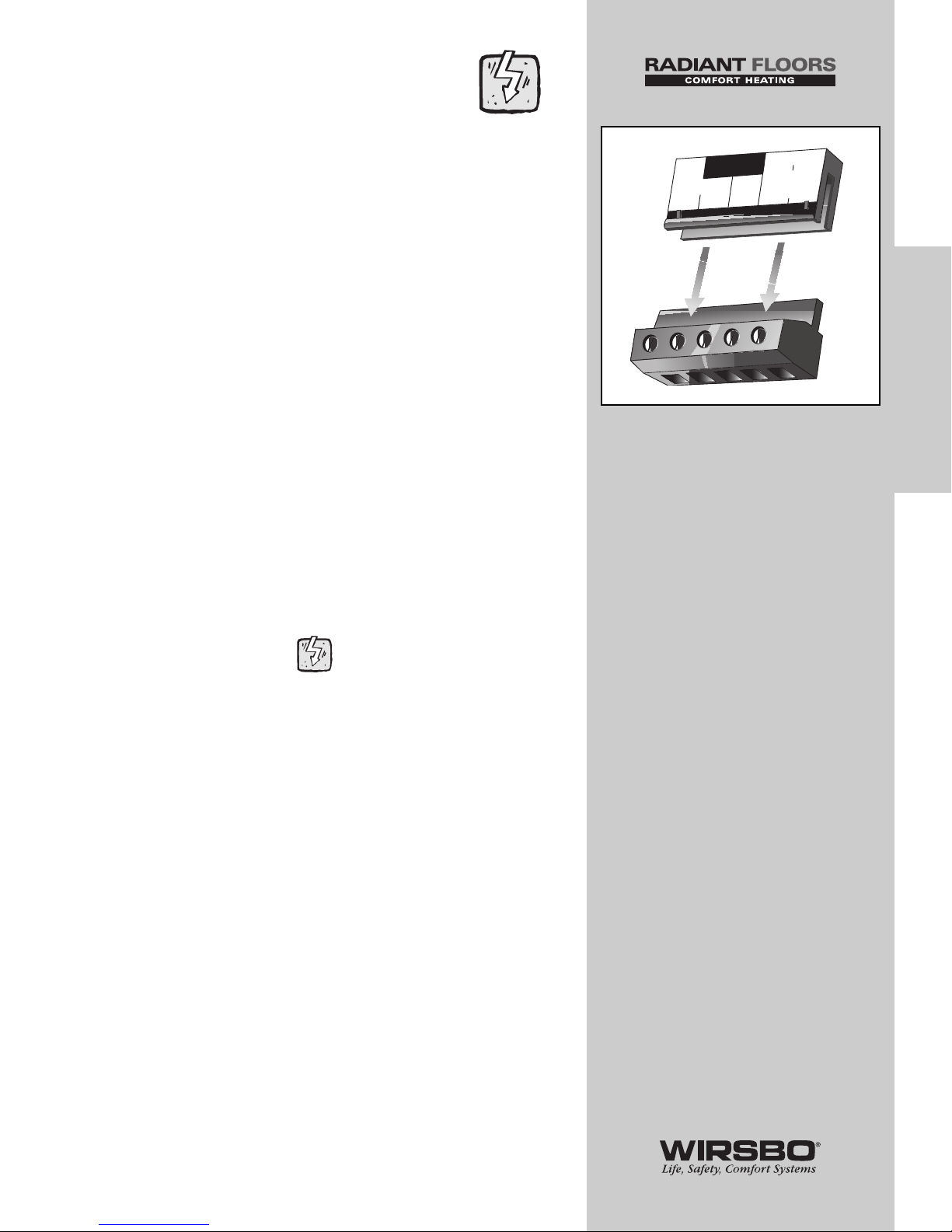
• Before supplying power for testing, each terminal block
must be unplugged from its header on the control
• To remove the terminal block, pull straight down from
the control (See fig. a)
• The following tests should only be carried out by
properly trained and experienced installers
• When testing, use standard testing practices and
procedures
• To properly test wiring and sensors, a good quality
electrical test meter capable of reading at least 0 – 300
VAC and at least 0 – 2,000,000 Ohms is essential
Test the Sensors
To test the sensors, the actual temperature at each sensor
location must be measured.
A good quality test meter capable of measuring up to 5,000 kΩ
(1 kΩ = 1000 Ω) is required to measure the sensor resistance.
In addition to this, the actual temperature must be measured
with either a good quality digital thermometer, or if a
thermometer is not available, a second sensor can be placed
alongside the one to be tested and the readings compared.
First measure the temperature using the thermometer and
then measure the resistance of the sensor at the control. The
wires from the sensor must not be connected to the control
while the test is performed. Using the chart on the previous
page, estimate the temperature measured by the sensor. The
sensor and thermometer readings should be close. If the test
meter reads a very high resistance, there may be a broken
wire, a poor wiring connection or a defective sensor. If the
resistance is very low, the wiring may be shorted, there may
be moisture in the sensor or the sensor may be defective. To
test for a defective sensor, measure the resistance directly at
the sensor location.
Do not apply voltage to a sensor at any time as damage
to the sensor may result.
29
INSTALLATION
INSTALLATION - Step 7 - Testing the Wiring
N
6
L
7
Power
8
9
10
Boil
P3
Boil Dem
Pmp P7
a
Page 32
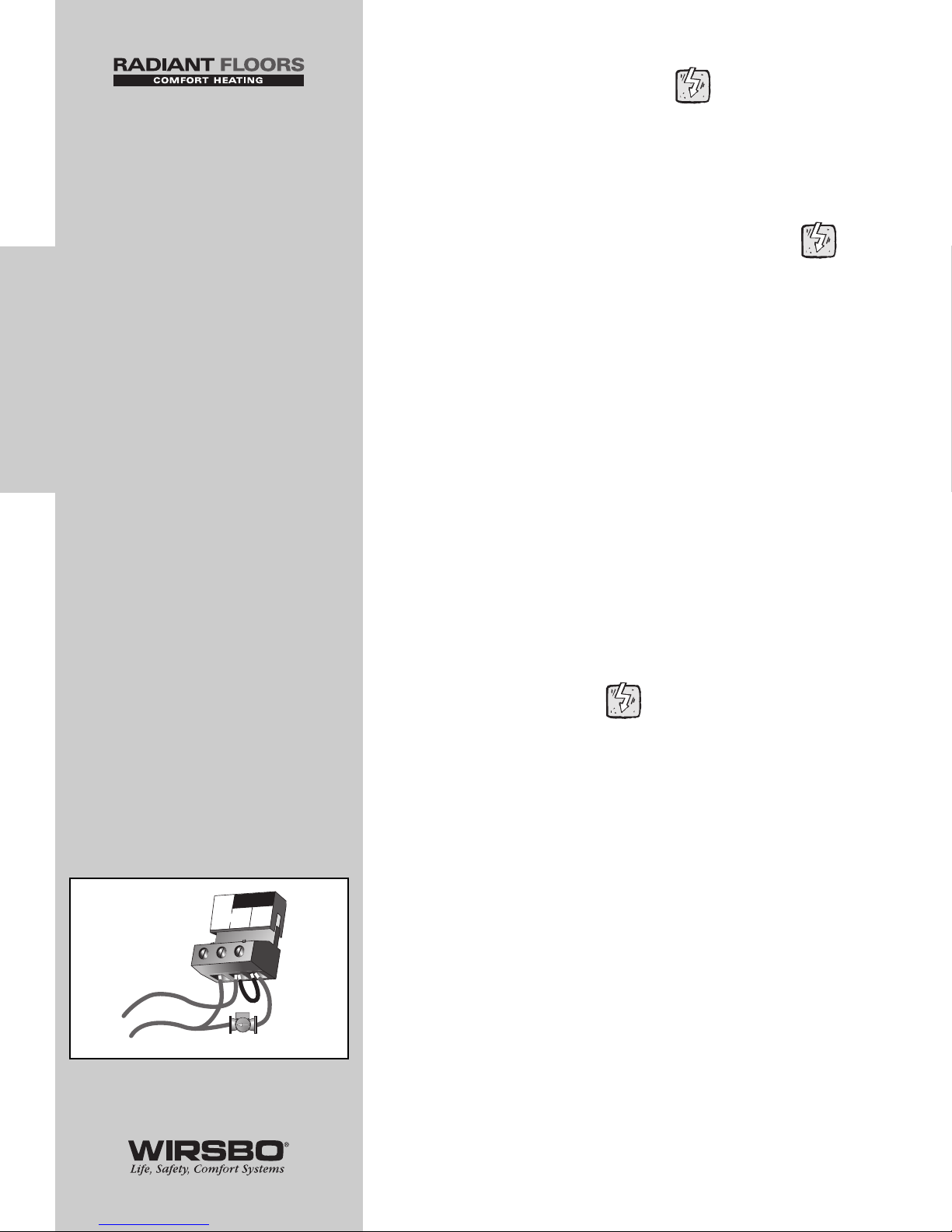
Test the Power Supply
1) Make sure exposed wires and bare terminals are not in
contact with other wires or grounded surfaces
2) Turn on the power and measure the voltage between the
Power L and Power N terminals (6 and 7) using an AC
voltmeter, the reading should be between 108 and 132 VAC
Test the Powered Demand Inputs
Voltage Readings for ALL Demand Devices
(described below)
1) When any of the demand devices described above calls for
heat, you should measure between 20 and 260 VAC at the
terminals
2) When these demand devices are off, you should measure
less than 5 VAC
Mixing Demand (if used)
• Measure voltage between Mix Demand terminals (1 and 2)
Boiler Demand (if used)
• Measure voltage between Boil Dem and Com Dem terminals
(3 and 4)
DHW Demand (if used)
• Measure voltage between DHW Dem and Com Dem
terminals (4 and 5)
Test the Outputs
IMPORTANT NOTE FOR ALL OUTPUT DEVICES:
Once you have verified a device operates properly,
shut off the power to the device and remove the
jumper installed during the testing procedure below.
If any device fails to start, see troubleshooting
information on page 32.
Primary Pump (Boil P3) — connected to
terminal (8) (See fig. a)
1) Make sure that power to terminal block is off
2) Install a jumper between Power L and Boil P3 terminals
(7 and 8)
3) When power is applied to the Power L and Power N terminals
(7 and 6) the primary pump should start
30
INSTALLATION
INSTALLATION - Step 7 - Testing the Wiring
120 VAC
L
N
6
7
L
Boil
P3
Power
8
N
a
Page 33
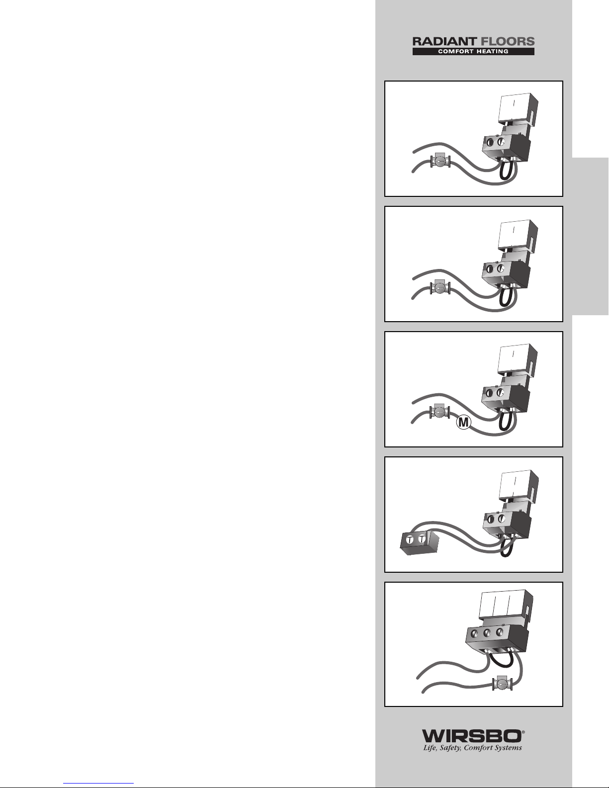
Boiler Demand Pump (Boil Dem Pmp P7) —
terminals (9 and 10) (See fig. b)
1) Make sure power to the pump circuit is off
2) Install a jumper between terminals (9 and 10)
3) When pump circuit is powered up, boiler demand pump
should start
Mixing System Pump (Mixing Pmp P1) —
terminals (11 and 12) (See fig. c)
1) Make sure power to the pump circuit is off
2) Install a jumper between terminals (11 and 12)
3) When the pump circuit is powered up, mixing system pump
should start
DHW Pump or Valve (DHW P6/ Vlv) —
(13 and 14) (See fig. d)
• Make sure power to the pump or valve circuit is off
• Install a jumper between terminals (13 and 14)
• When the DHW circuit is powered up, the DHW pump should
turn on or the DHW valve should open completely
Boiler — connected to the Boiler terminals
(15 and 16) (See fig. e)
• Make sure power to the boiler circuit is off
• Install a jumper between the terminals (15 and 16)
• When the boiler circuit is powered up, the boiler should fire
NOTE: Boiler may have a flow switch that prevents
firing until the primary pump (P3) is running.
Variable Speed Injection Pump (VSP P4) —
(17 and 19) (See fig. f)
• Make sure power to terminal block is off
• Install a jumper between the Pwr Mix and Cls/P4 terminals
(17 and 19)
• When the variable speed pump circuit is powered up, the
variable speed pump should operate at full speed
31
INSTALLATION
INSTALLATION - Step 7 - Testing the Wiring
Boil Dem
Pmp P7
9
10
120 VAC
L
N
b
Mixing
Pmp P1
11
12
120 VAC
L
N
c
DHW
P6/Vlv
13
14
120 VAC
L
N
d
15
16
Boiler
e
120 VAC
L
N
17
Pwr
Mix
18
19
Opn
Cls/
P4
f
Page 34
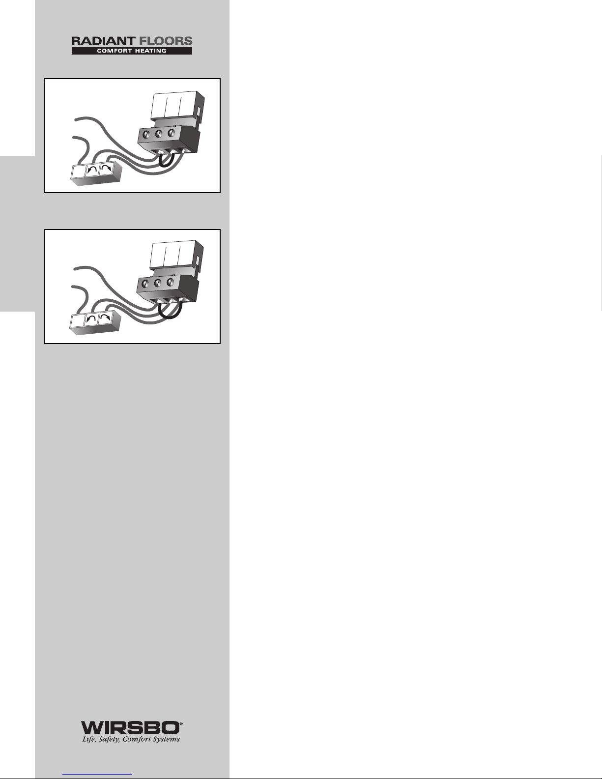
Mixing Valve Actuator — connected to Pwr Mix,
Opn and Cls / P4 terminals (17, 18 and 19)
STEP 1: (See fig. g)
• Make sure power to the motor circuit is off
• Install a jumper between the Pwr Mix and Opn terminals (17
and 18)
• Power up circuit , actuator should move in opening direction
NOTE: If the motor closes instead of opens,
wiring of actuating motor must be reversed
• If valve opens correctly, turn off the power to circuit and
remove the jumper before proceeding to STEP 2
STEP 2: (See fig. h)
• Install a jumper between the Pwr Mix and Cls/ P4 terminals
(17 and 19)
• Power up circuit , actuator should move in closing direction
• If motor closes correctly, turn off power to circuit and remove
jumper
Troubleshooting for ALL Output Devices
(described above)
• If the device does not start, check all wiring connections
• If the device still fails to start you may need to refer to the
manufacturers installation or troubleshooting information
supplied with the device
32
INSTALLATION
INSTALLATION - Step 7 - Testing the Wiring
17
18
19
24 or 1
20 VAC
R
C
Com
Pwr
Mix
Opn
Cls/
P4
g
17
Pwr
Mix
18
19
Opn
Cls/
P4
24 or 1
20 VAC
R
C
Com
h
Page 35
INSTALLATION - STEP 8
COMPLETING THE INSTALLATION
Once you have successfully tested all of the wiring and found
that everything is operational, you are ready to complete the
installation.
1) Make sure all power to the devices and terminal blocks is
off, and remove any remaining jumpers from the terminals
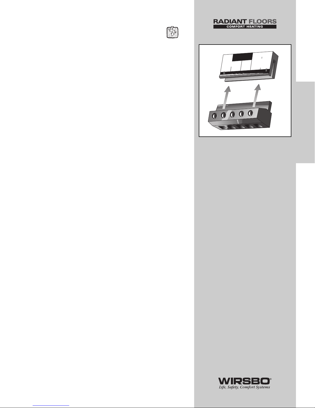
2) Reconnect the terminal blocks to the control by carefully
aligning them with their respective headers on the control
3) Push the terminal blocks into the headers — they should
snap firmly into place
(See fig. a)
4) Install supplied safety dividers between unpowered sensor
inputs and powered or 120 VAC wiring chambers
5) Apply power to the control
NOTE: The operation of the control on power up is
described in the Control Function Overview section
of this manual (page 58).
Cleaning The Control
• Moisten cloth with water and wring out prior to wiping control
• Do not use solvents or cleaning solutions on the control
33
INSTALLATION
INSTALLATION - Step 8 - Completing the Installation
N
6
L
7
Power
8
9
10
Boil
P3
Boil Dem
Pmp P7
a
Page 36

PROGRAMMING
TABLE OF CONTENTS
Step 1 – Programming the Control .............................. 35-55
DIP Settings ................................................ 35-36
Programming the "Misc" Menu .................... 37
Programming the "Adjust" Menu............ 38-55
A. Boiler/High Temp Zone Settings.... 38-41
B. DHW Settings.................................... 42-43
C. Mixing Device Settings.................... 44-49
D. Snow Melting Settings.................... 50-53
E. Boiler Operation Settings ................ 54-55
Step 2 – Test Sequence.................................................... 56-57
34
PROGRAMMING
PROGRAMMING - Table of Contents
Page 37
PROGRAMMING - STEP 1
PROGRAMMING THE CONTROL
GENERAL NOTE: This section is dedicated
to guiding you through the programming of
each function in a logical order based on area
of control. For more detailed functions of any
particular item, please refer to the Control
Overview Section.
IMPORTANT (PLEASE READ): The SYSTEMpro 311 is
now fully installed and ready for a trained, qualified
individual to begin entering the settings that will
help it control a hydronic radiant heating system
at its most efficient level.
Before you start PROGRAMMING you should:
1) REVIEW DIP Switch Settings below, as they affect what
items are available to be viewed and controlled through the
User Interface.
2) REVIEW The Control Function Overview if you are not
familiar with how the control functions operate in
conjunction with the specific systems installed.
DIP SWITCH SETTINGS:
About DIP Switch Settings
• DIP switch settings on the control are very important and
should be set to appropriate settings prior to making any
adjustments to the control
• DIP switch settings change the items that are available to be
viewed and/or adjusted in the control
• If a DIP switch is changed while control is powered up, the
control responds to the setting change by returning the
display to the View menu. This is true for all the DIP switches
except for the Lock / Unlock DIP switch
35
PROGRAMMING
PROGRAMMING - Step 1 - Programming the Control
Page 38
Lock/Unlock DIP Switch Setting
(Factory Setting is Unlock)
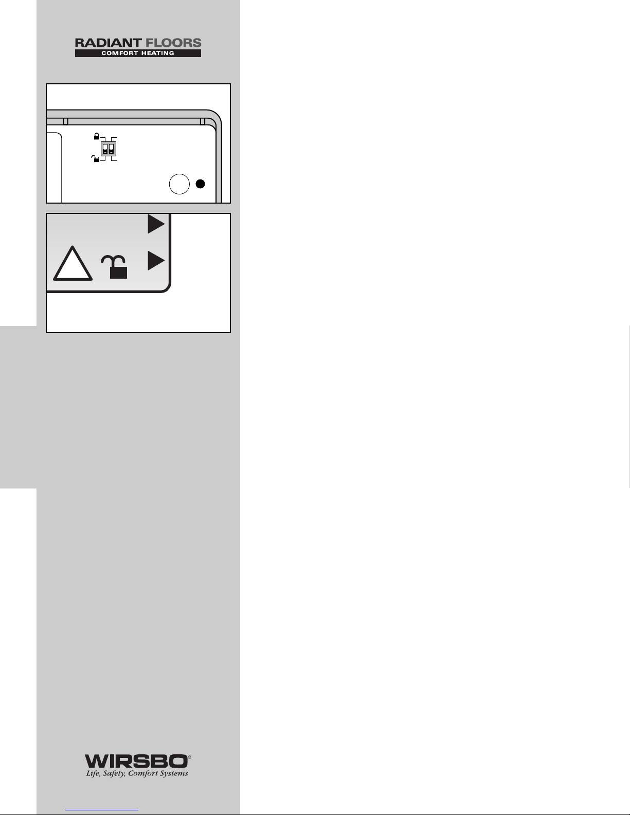
• Lock/Unlock DIP switch is used to lock and unlock the access
level of the control
(See fig. a)
• In locked mode, access levels cannot be changed
• A small icon representing a padlock is shown in the bottom
right hand corner of the display, indicating if control is locked
or unlocked
(See fig. b)
• To change the access level, set the DIP switch to the
unlocked, or down position. The current access level of the
control is viewed in its Miscellaneous (Misc) Menu.
• While viewing the access level, use the “up” and “down”
buttons to select between the Limited (LTD), User (USER),
Installer (INST) or Advanced (ADV) access levels
• To lock the access level, select the appropriate access level in
the Miscellaneous (Misc) Menu and move the DIP switch
from unlocked position to the locked position
• As long as the DIP switch is in the locked position, the access
level of the control can no longer be viewed or adjusted in its
Miscellaneous (Misc) Menu
Snow Melting / Mixing Reset
(Factory Setting is Mixing Reset)
• The Snow Melting / Mixing Reset DIP switch sets the
operating mode of the mixing system
• When DIP switch is set to the Mixing Reset setting, the
mixing system is used to supply heat to a building’s heating
system
• The control uses a reset ratio method of outdoor reset that
matches the heating load
• When this setting is used, a desired indoor air setting, design
outdoor setting and a design supply setting must be entered
into the control to create the reset ratio curve
• When the DIP switch is set to the Snow Melting setting, the
mixing system is used to supply heat to a single zone snow
melting system
36
PROGRAMMING
PROGRAMMING - Step 1 - Programming the Control
Max
i
Melt
!
Sto
p
b
Snow Melting
Mixing Reset
Test
a
Page 39
PROGRAMMING THE “MISC” MENU
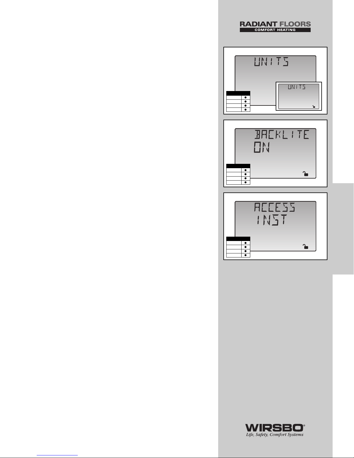
UNITS (See fig. a)
1) Go to UNITS item field in Miscellaneous (MISC) Menu
2) Select the temperature measurement units you wish all
temperatures to be displayed in
RANGE: °F, °C
DEFAULT: °F
BACKLITE (See fig. b)
1) Go to BACKLITE item field in Miscellaneous (MISC) Menu
2) Select the operating mode for the backlighting function of
the LCD as well as the time of keypad inactivity until the
control automatically returns to the default display
RANGE: OFF, 90 sec., ON
DEFAULT: ON
ACCESS (See fig. c)
1) Go to ACCESS item field in Miscellaneous (MISC) Menu
2) Select the level of access that you wish to be used by
the control
RANGE: ADV (Advanced), INST (Installer), USER (User),
LTD (Limited)
DEFAULT: INST (Installer)
NOTE: For more information on Access Levels
refer to Navigating the Control in the Introduction
section (page 4).
37
PROGRAMMING
PROGRAMMING - Step 1 - Programming the Control
Misc
o
F
a
Misc
sec
b
Misc
c
Access Level
LTD
USER
INST
ADV
Misc
o
C
Access Level
LTD
USER
INST
ADV
Access Level
LTD
USER
INST
ADV
Page 40
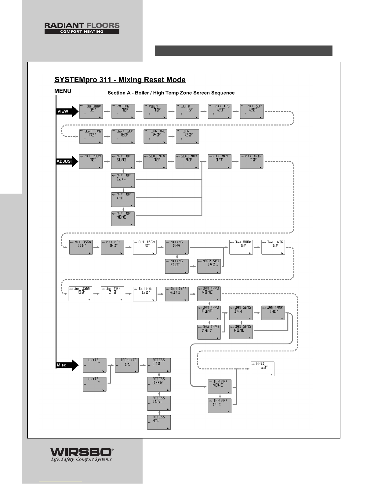
PROGRAMMING
THE
“ADJUST” MENU
A. BOILER / HIGH TEMP ZONE SETTINGS
38
PROGRAMMING
PROGRAMMING - Step 1 - Programming the Control
Page 41
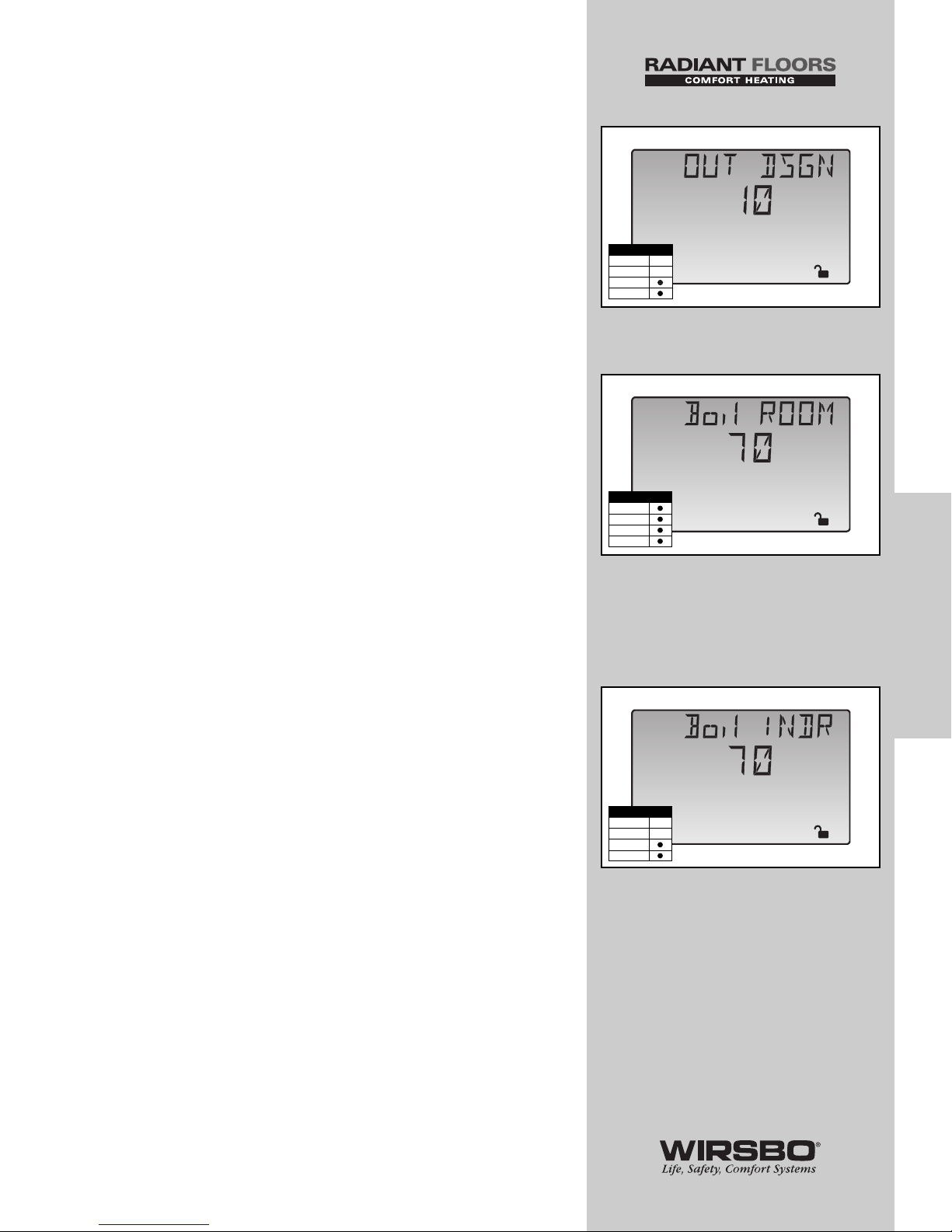
OUTDOOR DESIGN (OUT DSGN) (See fig. a)
1) Go to OUT DSGN item field in Adjust Menu
2) Set to the outdoor design temperature used in the heat-loss
calculation
RANGE: -60 to 50°F (-51 to 10°C)
DEFAULT: 10°F (-12°C)
BOILER ROOM (Boil ROOM) (See fig. b)
1) Go to Boil ROOM item field in Adjust Menu
2) Set to the desired room temperature for the boiler/high
temp zones
RANGE: 35 to 100°F (2 to 38°C)
DEFAULT: 70°F (21°C)
NOTE: There is only a ±3°F (±1°C)
adjustment in the LTD Access Level.
BOILER INDOOR (Boil INDR) (See fig. c)
1) Go to Boil INDR item field in Adjust Menu
2) Set to the room temperature used in original building heatloss calculations of the building
RANGE: 35 to 100°F (2 to 38°C)
DEFAULT: 70°F (21°C)
39
PROGRAMMING
PROGRAMMING - Step 1 - Programming the Control
Adjust
o
F
c
Access Level
LTD
USER
INST
ADV
Adjust
o
F
b
Access Level
LTD
USER
INST
ADV
Adjust
o
F
a
Access Level
LTD
USER
INST
ADV
Page 42
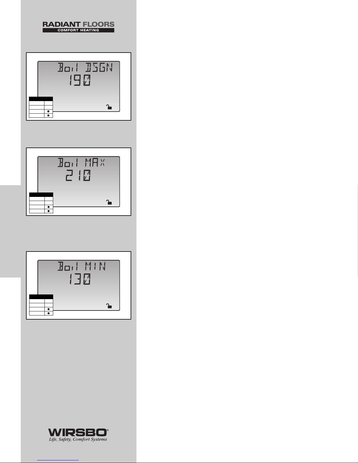
BOILER DESIGN (Boil DSGN) (See fig. d)
1) Go to Boil DSGN item field in Adjust Menu
2) Set to the design supply water temperature calculated in
the heat-loss to satisfy the boiler/high temp zones
RANGE: 70 to 220°F (21 to 104°C)
DEFAULT: 190°F (88°C)
BOILER MAXIMUM (Boil MAX) (See fig. e)
1) Go to Boil MAX item field in Adjust Menu
2) Set to the lowest water temperature that the control is
allowed to use as a boiler target temperature (Refer to the
boiler manufacturer’s literature)
RANGE: 120 to 225°F, OFF (49 to 107°C, OFF)
DEFAULT: 210°F (99°C)
BOILER MINIMUM (Boil MIN) (See fig. f)
1) Go to Boil MIN item field in Adjust Menu
2) Set to the lowest water temperature the boiler is capable of
receiving without condensing (Refer to the boiler
manufacturer’s literature)
RANGE: OFF, 80 to 180°F (OFF, 27 to 82°C)
DEFAULT: 130°F (54°C)
NOTE: If boiler is designed for condensing
operation, set the Boil MIN adjustment to OFF.
40
PROGRAMMING
PROGRAMMING - Step 1 - Programming the Control
Adjust
o
F
f
Access Level
LTD
USER
INST
ADV
Adjust
o
F
e
Access Level
LTD
USER
INST
ADV
Adjust
o
F
d
Access Level
LTD
USER
INST
ADV
Page 43
41
PROGRAMMING
PROGRAMMING - Step 1 - Programming the Control
Adjust
o
F
g
Access Level
LTD
USER
INST
ADV
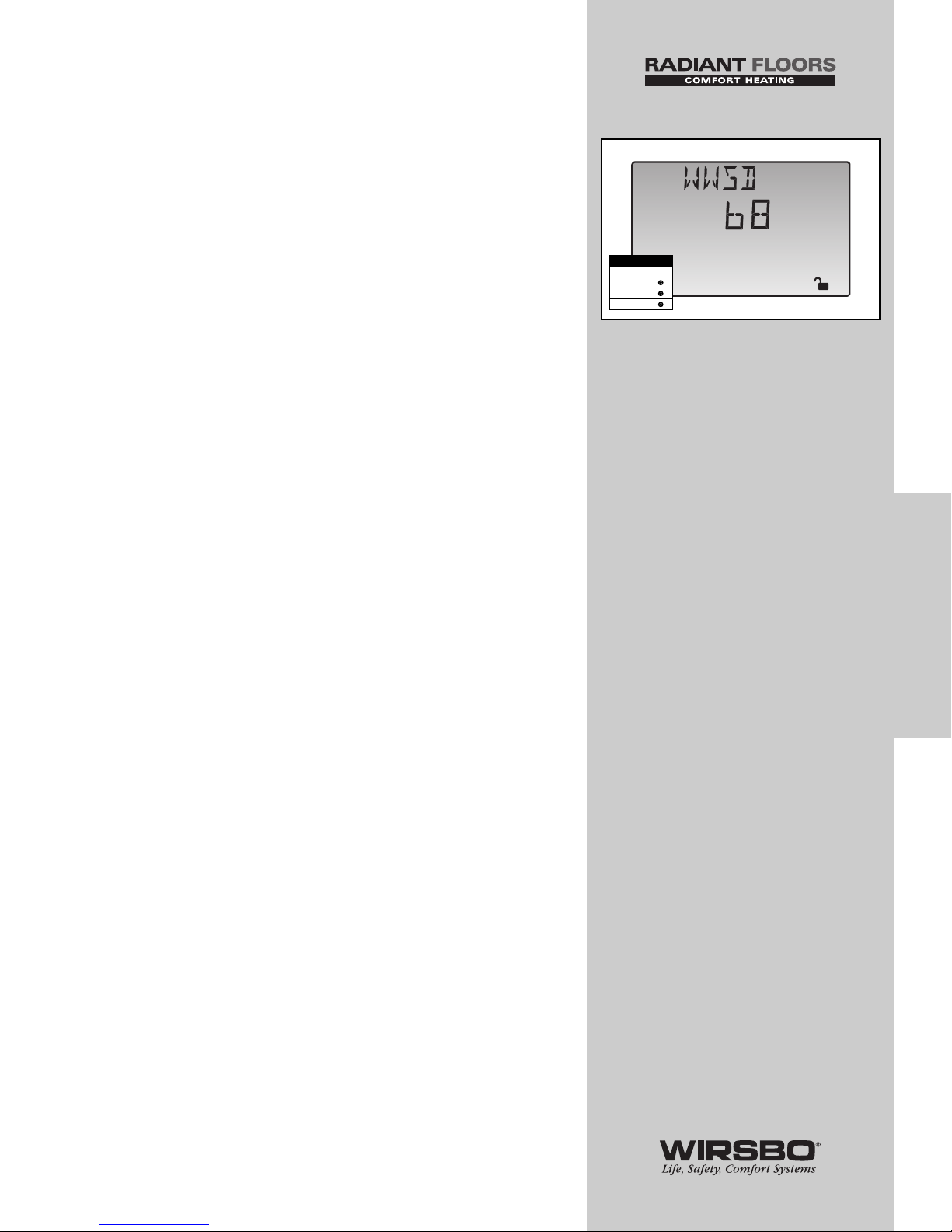
WARM WEATHER SHUT DOWN (WWSD)
(See fig. g)
The control enters into WWSD when slab and outdoor
temperatures exceed MELTING temperature by more than
1.5°F (1°C).
1) Go to WWSD item field in the Adjust Menu
2) Set to an outdoor temperature at which the system no
longer needs to heat the zone to maintain a comfortable
temperature inside
RANGE: 35 to 100°F, OFF (2 to 38°C, OFF)
DEFAULT: 68°F (21°C)
Page 44
PROGRAMMING
THE
“ADJUST” MENU
B. DHW SETTINGS
42
PROGRAMMING
PROGRAMMING - Step 1 - Programming the Control
Page 45
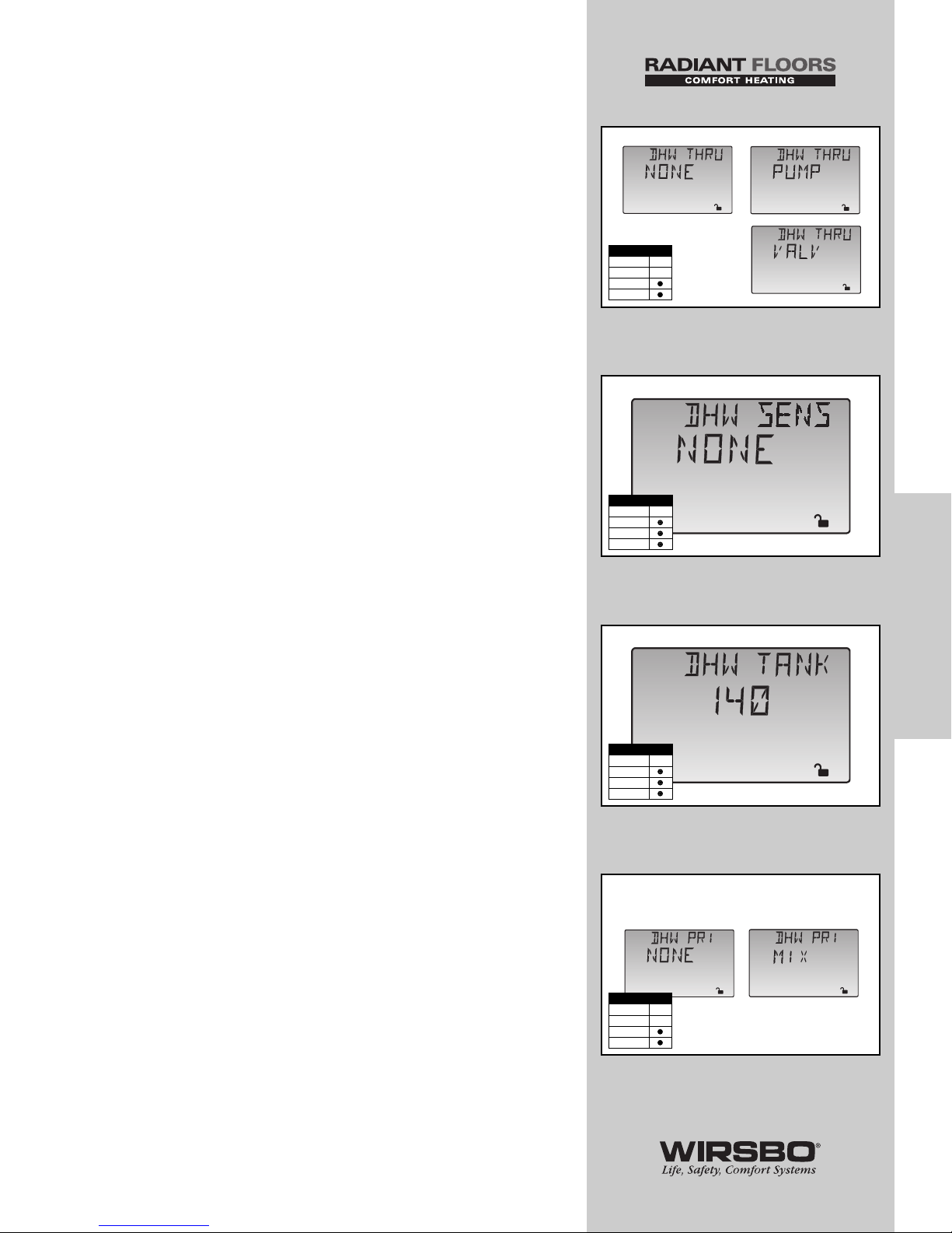
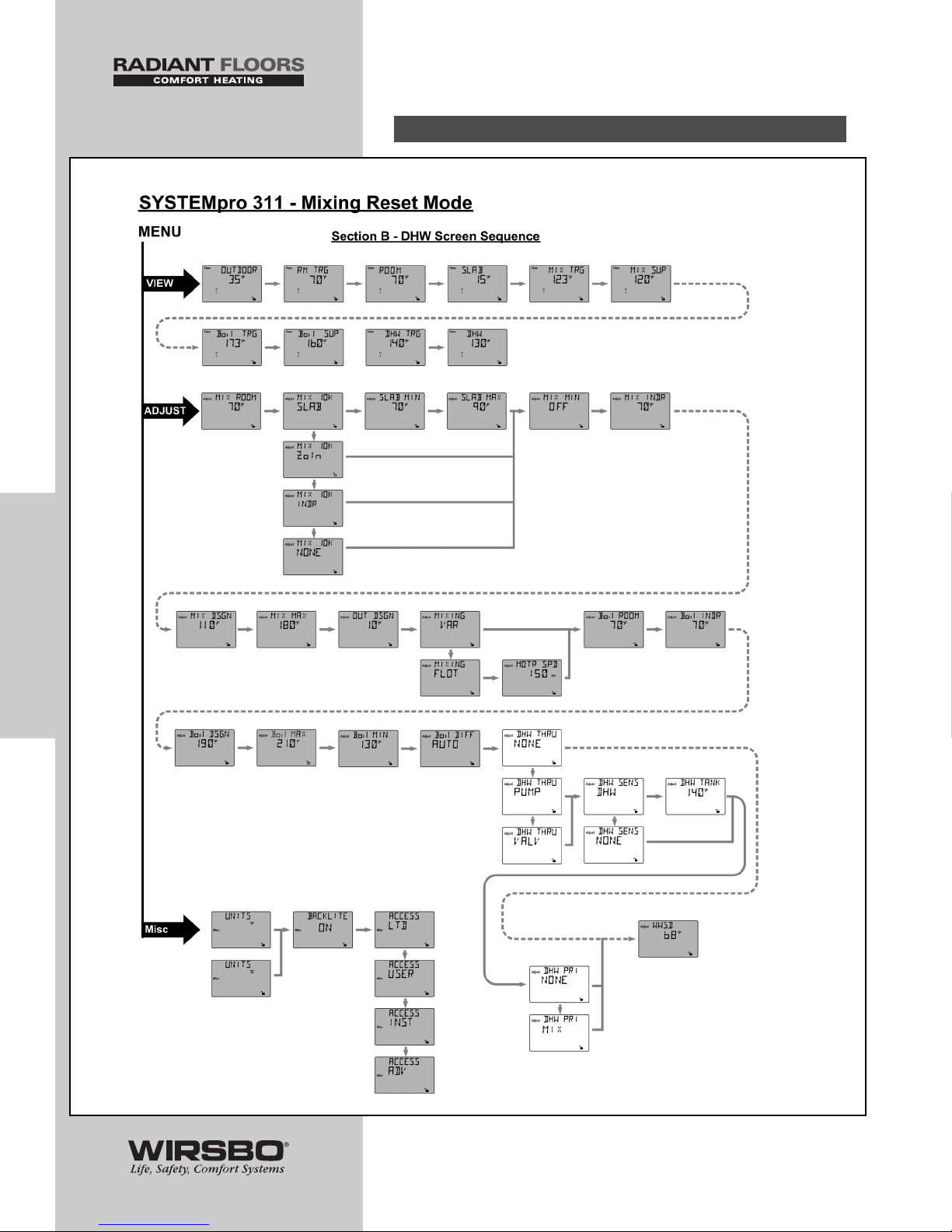
DHW DEVICE (DHW THRU) (See fig. h)
1) Go to DHW THRU item field in Adjust Menu
2) Select the type of DHW device you are using to supply flow
to the heat exchange in the DHW tank
RANGE: NONE, PUMP, VALV
DEFAULT: PUMP
DHW SENSOR (DHW SENS) (See fig. i)
1) Go to DHW SENS item field in Adjust Menu
2) Select whether or not a DHW Sensor is being used to
measure the DHW TANK temperature
RANGE: NONE, DHW
DEFAULT: NONE
DHW TANK (DHW TANK) (See fig. j)
1) Go to DHW THRU item field in Adjust Menu (This needs to
be set to VALV or PUMP before DHW TANK temperature can
be selected)
2) Go to DHW SENS item field in Adjust Menu
3) Set DHW SENS to DHW
4) Go To DHW TANK item field in Adjust Menu
5) Set the desired DHW storage tank temperature
RANGE: OFF, 70 to 190°F (OFF, 21 to 88°C)
DEFAULT: 140°F (60°C)
NOTE: If DHW THRU is set to NONE,
this menu will not be available.
NOTE: DHW TANK should only be selected
if a universal sensor is used in the tank.
DHW PRIORITY (DHW PRI) (See fig. k)
1) Go to DHW THRU item field in Adjust Menu (This needs
to be set to VALV or PUMP before priority can be selected)
2) Go to DHW PRI item field in Adjust Menu
3) Select the portions of the heating system that the DHW
will have priority over. Your choices are Mixing Priority
or NONE
RANGE: NONE, MIX
DEFAULT: NONE
NOTE: If DHW THRU is set to NONE,
this menu will not be available.
43
PROGRAMMING
PROGRAMMING - Step 1 - Programming the Control
Adjust
h
Adjust
k
Adjust
Adjust
Adjust
Access Level
LTD
USER
INST
ADV
Access Level
LTD
USER
INST
ADV
Adjust
o
F
j
Access Level
LTD
USER
INST
ADV
Adjust
i
Access Level
LTD
USER
INST
ADV
Page 46
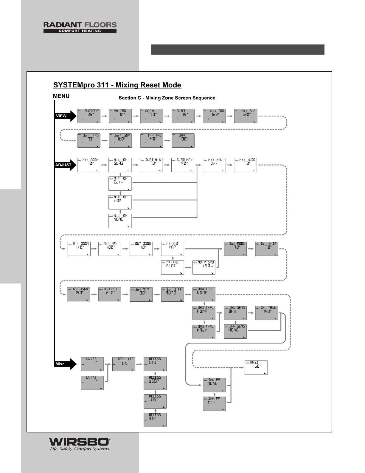
PROGRAMMING
THE
“ADJUST” MENU
(DIP set to Mixing Reset)
C. MIXING DEVICE SETTINGS
44
PROGRAMMING
PROGRAMMING - Step 1 - Programming the Control
Page 47
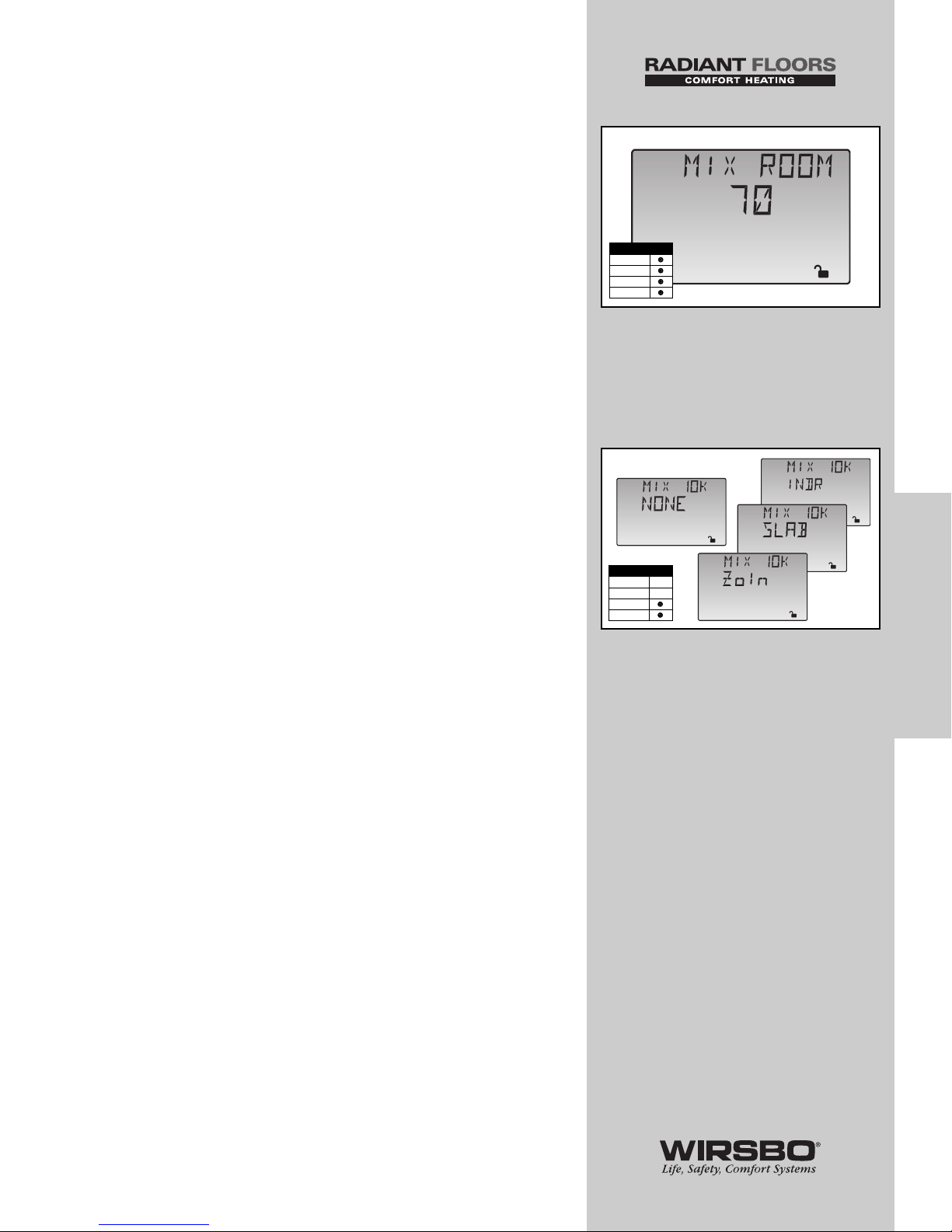
MIXING ROOM (MIX ROOM) (See fig. l)
1) Go to MIX ROOM item field in Adjust Menu
2) Set to the desired room temperature for mixing zones
NOTE: There is only a ±3°F (±1°C)
adjustment in the LTD Access Level.
DIP SETTING: Mixing Reset
RANGE: 35 to 100°F (2 to 38°C)
DEFAULT: 70°F (21°C)
NOTE: Used to shift the reset ratio parallel for
temporarily higher/lower room temperature.
10K INDOOR SENSOR (MIX 10K ) (See fig. m)
1) Go to MIX 10K item field in Adjust Menu
2) To add an indoor sensor for temperature control of a single
zone mixing system, set to INDR
3) To add indoor temperature feedback control from a tekmar
zone control, set to ZoIn
4) To add a slab sensor for temperature control for snow
melting, set to SLAB
RANGE: NONE, INDR, ZoIn, SLAB (only if MIX MIN = OFF)
DEFAULT: NONE
45
PROGRAMMING
PROGRAMMING - Step 1 - Programming the Control
Adjust
o
F
l
Access Level
LTD
USER
INST
ADV
Adjust
m
Adjust
Adjust
Access Level
LTD
USER
INST
ADV
Adjust
Page 48
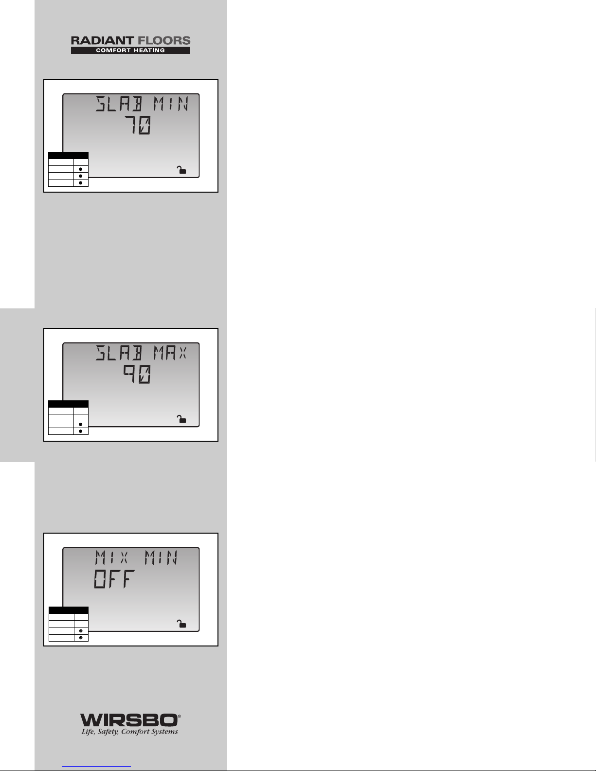
SLAB MINIMUM (SLAB MIN) (See fig. n)
1) Go to MIX 10K item field in Adjust Menu
2) Set MIX 10K to SLAB
3) Go to SLAB MIN item field in Adjust Menu
4) Set the minimum allowed core temperature of slab as long
as the control is not in WWSD
NOTE: Caution should be used when adjusting SLAB
MIN setting as this may lead to overheating of zone
during mild conditions.
RANGE: OFF, 35 to 120°F (OFF, 2 to 49°C)
DEFAULT: 70°F (21°C)
NOTE: The SLAB MIN and the SLAB MAX screens
are only available if SLAB is selected in the MIX 10K
screen
SLAB MAXIMUM (SLAB MAX) (See fig. o)
1) Go to MIX 10K item field in Adjust Menu
2) Set MIX 10K to SLAB
3) Go to SLAB MAX item field in Adjust Menu
4) Set the maximum allowed core temperature of slab
NOTE: If slab is to be maintained at a fixed core
temperature, set SLAB MAX and SLAB MIN items to
the same setting.
RANGE: 40 to 150°F (4 to 66°C)
DEFAULT: 90°F (32°C)
MIXING MINIMUM (MIX MIN) (See fig. p)
1) Go to MIX MIN item field in Adjust Menu
2) Set to the lowest temperature control is allowed to use as
MIX TRG temperature
DIP SETTING: Mixing Reset
RANGE: OFF, 35 to 150°F (OFF, 2 to 66°C)
DEFAULT: OFF
46
PROGRAMMING
PROGRAMMING - Step 1 - Programming the Control
Adjust
p
Access Level
LTD
USER
INST
ADV
Adjust
o
F
o
Access Level
LTD
USER
INST
ADV
Adjust
o
F
n
Access Level
LTD
USER
INST
ADV
Page 49
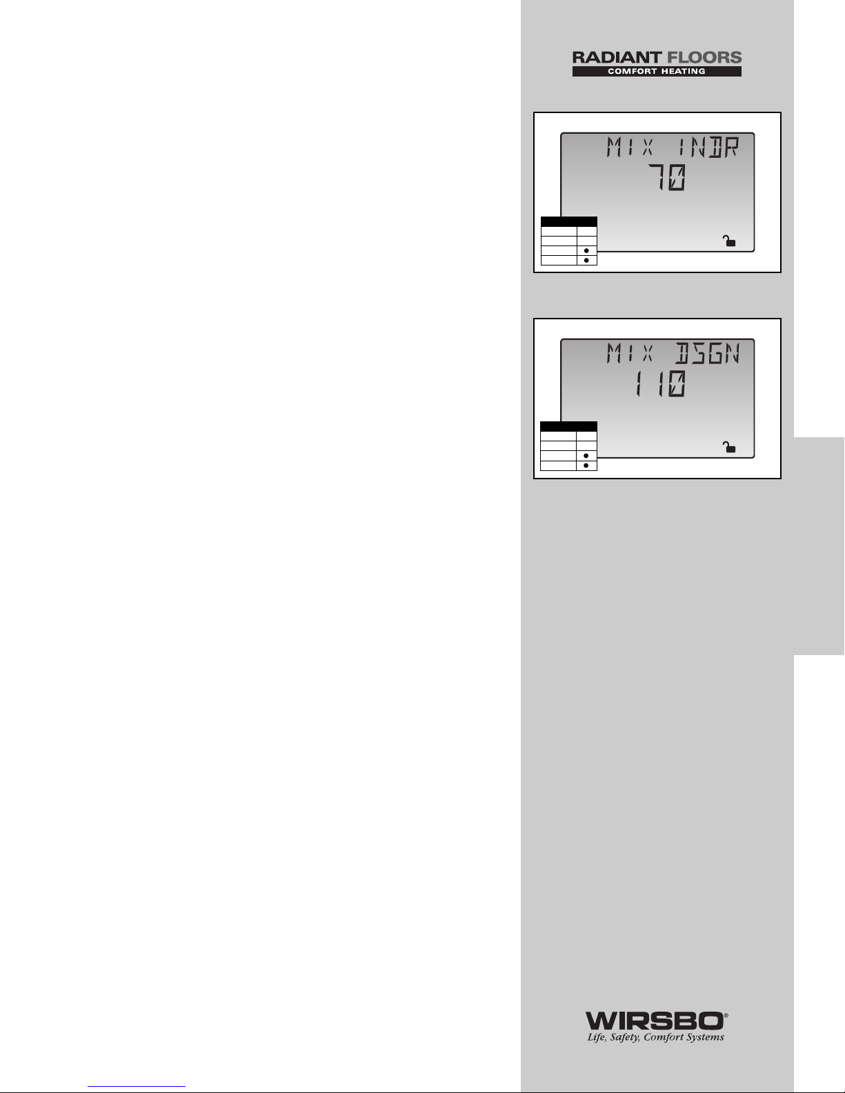
MIXING INDOOR (MIX INDR) (See fig. q)
1) Go to MIX INDR item field in Adjust Menu
2) Set to the room temperature used in original heat-loss
calculations for the building (Normally 65 to 70°F)
DIP SETTING: Mixing Reset
RANGE: 35 to 100°F (2 to 38°C)
DEFAULT: 70°F (21°C)
MIXING DESIGN (MIX DSGN) (See fig. r)
1) Go to MIX DSGN item field in Adjust Menu
2) Set to the design supply water temperature calculated in
heat-loss calculation for the mixing zones
DIP SETTING: MIXING RESET
RANGE: 70 to 220°F (21 to 104°C)
DEFAULT: 110°F (43°C)
47
PROGRAMMING
PROGRAMMING - Step 1 - Programming the Control
Adjust
o
F
r
Access Level
LTD
USER
INST
ADV
Adjust
o
F
q
Access Level
LTD
USER
INST
ADV
Page 50
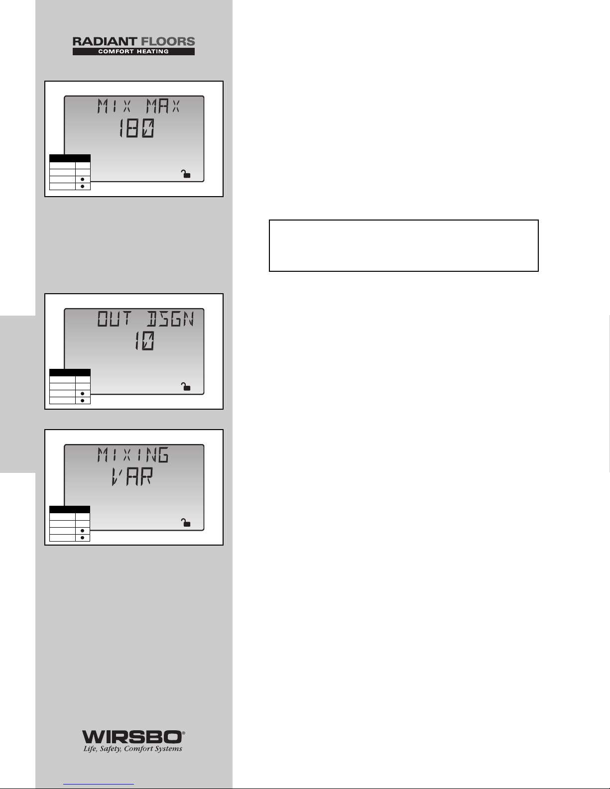
MIXING MAXIMUM (MIX MAX) (See fig. s)
1) Go to MIX MAX item field in Adjust Menu
2) Set to highest water temperature the control is allowed to
use as MIX TRG temperature
RANGE: 80 to 210°F, OFF (27 to 99°C, OFF)
DEFAULT: 180°F (82°C)
NOTE: Do not exceed the water temperatures
shown for the following construction methods.
OUTDOOR DESIGN (OUT DSGN) (See fig. t)
1) Go to OUT DSGN item field in Adjust Menu
2) Set to the outdoor design temperature used in the heat-loss
calculation
RANGE: -60 to 50°F (-51 to 10°C)
DEFAULT: 10°F (-12°C)
MIXING DEVICE SELECTION (MIXING) (See fig. u)
1) Go to MIXING item field in Adjust Menu
2) Set the type of mixing device used (floating action mixing
valve “FLOT” or variable speed injection pump “VAR”)
RANGE: FLOT (Floating), VAR (Variable Speed)
DEFAULT: VAR
48
PROGRAMMING
PROGRAMMING - Step 1 - Programming the Control
Adjust
u
Access Level
LTD
USER
INST
ADV
Adjust
o
F
t
Access Level
LTD
USER
INST
ADV
• Concrete 150°F
• Poured Underlayment 140°F
• Radiant Wall/Ceiling 120°F
(using drywall)
• Joist No Plates 180°F
• Joist w/Plates 165°F
• Quik Trak
®
180°F
Adjust
o
F
s
Access Level
LTD
USER
INST
ADV
Page 51
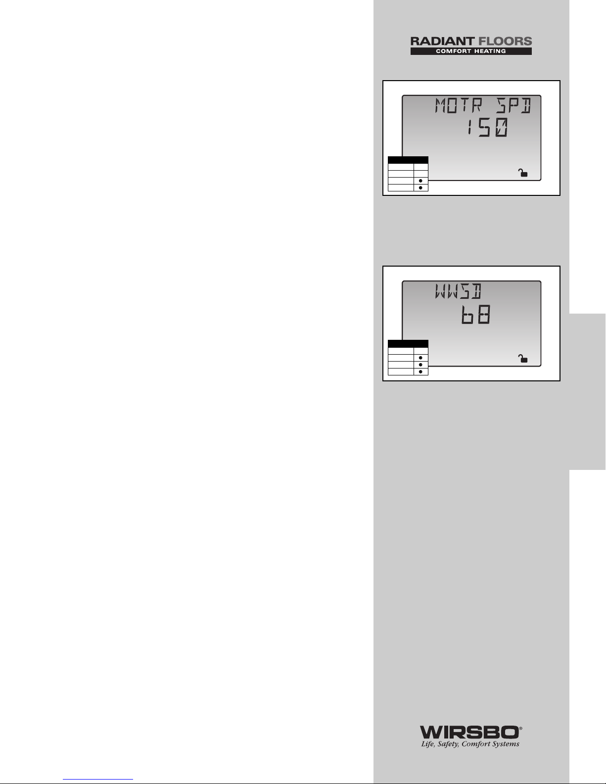
MOTOR SPEED (MOTR SPD) (See fig. v)
NOTE: For a Floating Action Valve Mixing Device only.
1) Go to MIXING item field in Adjust Menu
2) Set MIXING to FLOT
3) Go to MOTR SPD item field in Adjust Menu
4) Set the time the actuating motor requires to operate from
fully closed to fully open
RANGE: 30 to 230 sec
DEFAULT: 150 sec
WARM WEATHER SHUT DOWN (WWSD)
(See fig. w)
The control enters into WWSD when slab and outdoor
temperatures exceed MELTING temperature by more than
1.5°F (1°C).
1) Go to WWSD item field in the Adjust Menu
2) Set to an outdoor temperature at which the system no
longer needs to heat the zone to maintain a comfortable
temperature inside
RANGE: 35 to 100°F, OFF (2 to 38°C, OFF)
DEFAULT: 68°F (21°C)
49
PROGRAMMING
PROGRAMMING - Step 1 - Programming the Control
Adjust
sec
v
Access Level
LTD
USER
INST
ADV
Adjust
o
F
w
Access Level
LTD
USER
INST
ADV
Page 52
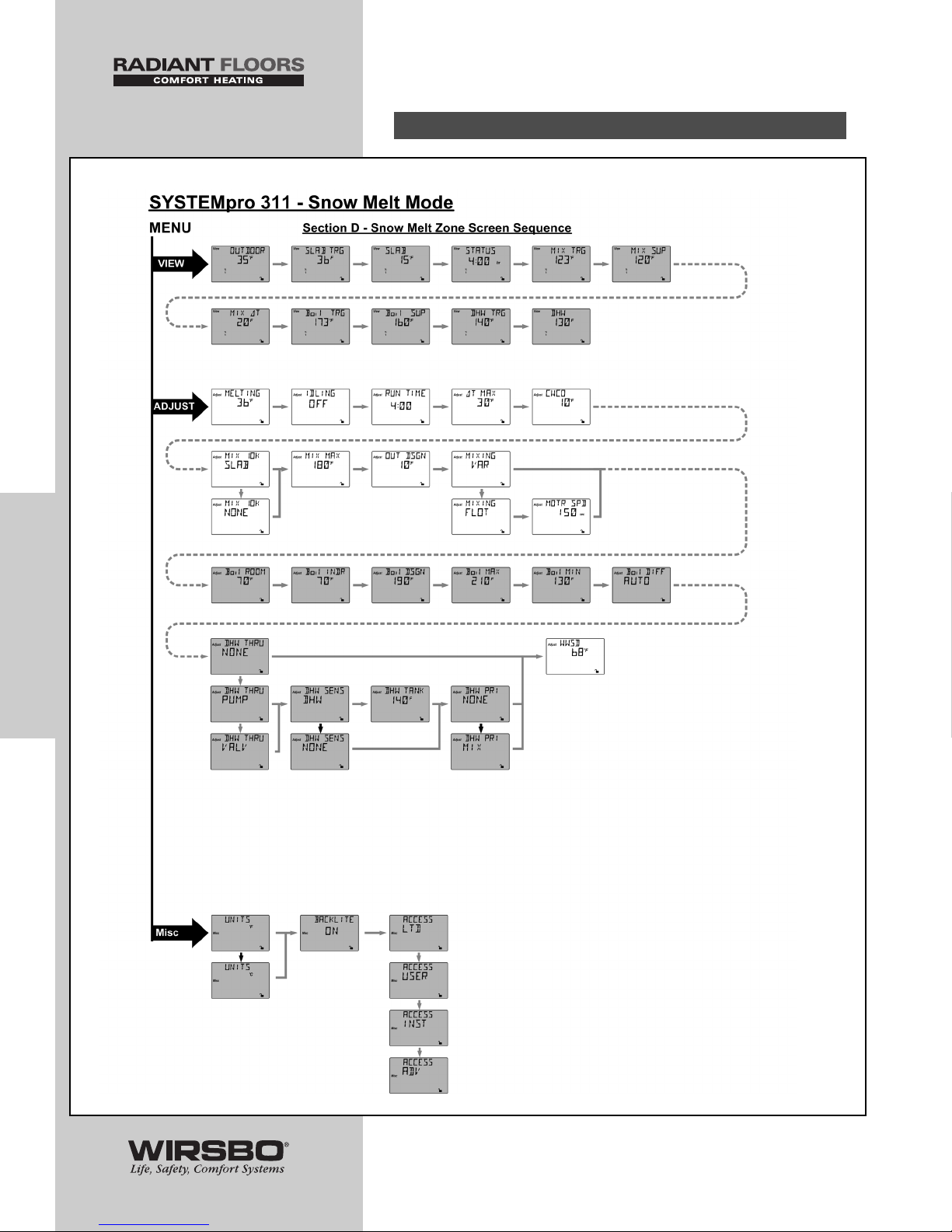
PROGRAMMING
THE
“ADJUST” MENU
D. SNOW MELTING SETTINGS
50
PROGRAMMING
PROGRAMMING - Step 1 - Programming the Control
Page 53
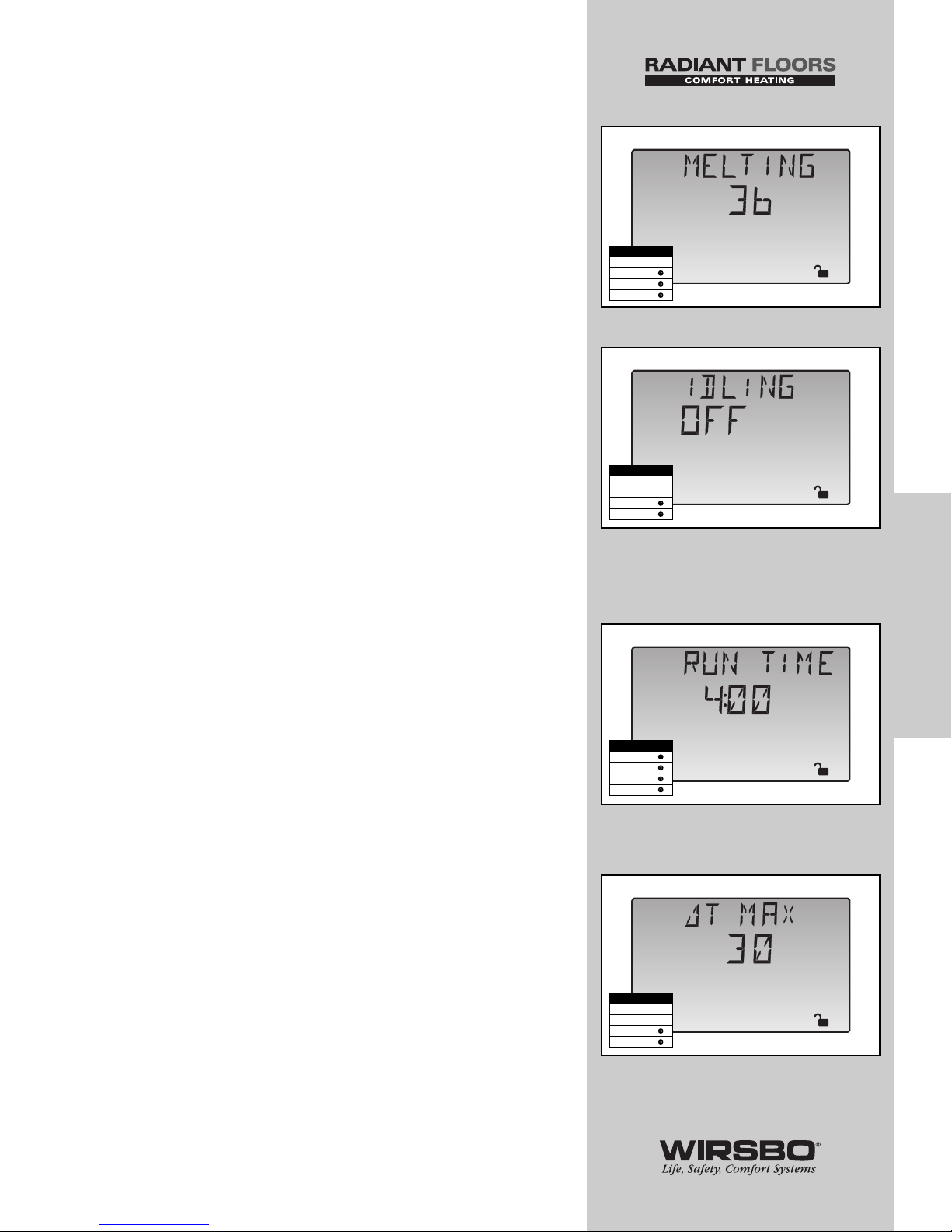
MELTING MODE (MELTING) (See fig. x)
1) Go to MELTING item field in View Menu
2) Set the slab surface temperature to be maintained while the
control is in melting mode
DIP SWITCH: Snow Melting
RANGE: 32 to 95°F (0 to 35°C)
DEFAULT: 36°F (2°C)
IDLING MODE (IDLING) (See fig. y)
Idle feature decreases melting start up time maintaining slab
at an “Idling” temperature.
1) Go to IDLING item field in View Menu
2) Set the slab surface temperature that you wish to maintain
while control is in idling mode
DIP SWITCH: Snow Melting
RANGE: OFF, 20 to 95°F (OFF, -7 to 35°C)
DEFAULT: OFF
RUNNING TIME (RUN TIME) (See fig. z)
The length of time the snow melting system operates once the
slab has reached melting temperature.
1) Go to RUN TIME item field in Adjust Menu
2) Set the time in which slab is to be operated at Melting
temperature during a melting demand
RANGE: 0:30 to 17:00 hr, INF (Infinite)
DEFAULT: 4:00 hr
SLAB PROTECTION (∆T MAX) (See fig. aa)
1) Go to ∆T MAX item field in Adjust Menu
2) Set ∆T MAX (delta T) — the temperature difference between
slab supply and slab return temperature
NOTE: The rate at which heat is applied to slab
can be controlled and thermal stresses in slab can
be minimized by limiting this temperature difference.
DIP SWITCH: Snow Melting
RANGE: 10 to 70°F, OFF (6 to 39°C, OFF)
DEFAULT: 30°F (17°C)
51
PROGRAMMING
PROGRAMMING - Step 1 - Programming the Control
Adjust
hr
z
Access Level
LTD
USER
INST
ADV
Adjust
y
Access Level
LTD
USER
INST
ADV
Adjust
o
F
x
Access Level
LTD
USER
INST
ADV
Adjust
o
F
aa
Access Level
LTD
USER
INST
ADV
Page 54
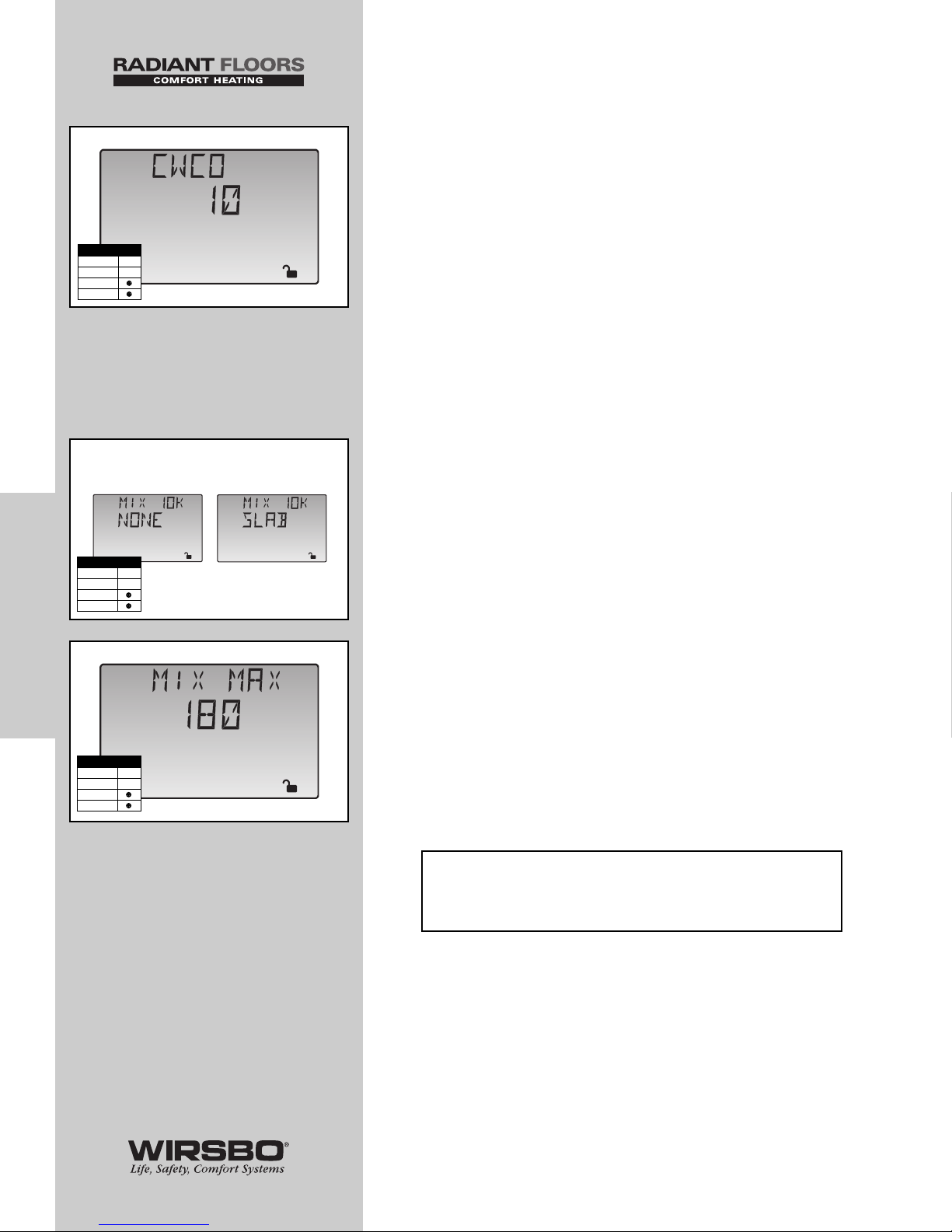
COLD WEATHER CUT OUT (CWCO) (See fig. bb)
Maintaining slab at either melting or idling temperature
during extremely cold temperatures can be expensive or
impossible. To set a Cold Weather Cut Out:
1) Go to CWCO item field in Adjust Menu
2) Set CWCO to the temperature which you wish the
snowmelt system to turn off once the outdoor temperature
drops below that point
DIP SWITCH: Snow Melting
RANGE: OFF, -30 to 50°F (OFF, -34 to 10°C)
DEFAULT: 10°F (-12°C)
10K INDOOR SENSOR (MIX 10K ) (See fig. cc)
1) Go to MIX 10K item field in Adjust Menu
2) To add a slab sensor for temperature control for snow
melting, set to SLAB
RANGE: NONE, SLAB
DEFAULT: NONE
MIXING MAXIMUM (MIX MAX) (See fig. dd)
1) Go to MIX MAX item field in Adjust Menu
2) Set to highest water temperature control is allowed to use
as MIX TRG temperature
RANGE: 80 to 210°F, OFF (27 to 99°C, OFF)
DEFAULT: 180°F (82°C)
NOTE: Do not exceed the water temperatures
shown for the following construction methods.
52
PROGRAMMING
PROGRAMMING - Step 1 - Programming the Control
Adjust
o
F
bb
Access Level
LTD
USER
INST
ADV
Adjust
cc
Adjust
Access Level
LTD
USER
INST
ADV
Adjust
o
F
dd
Access Level
LTD
USER
INST
ADV
• Concrete 150°F
• Poured Underlayment 140°F
• Radiant Wall/Ceiling 120°F
(using drywall)
• Joist No Plates 180°F
• Joist w/Plates 165°F
• Quik Trak
®
180°F
Page 55
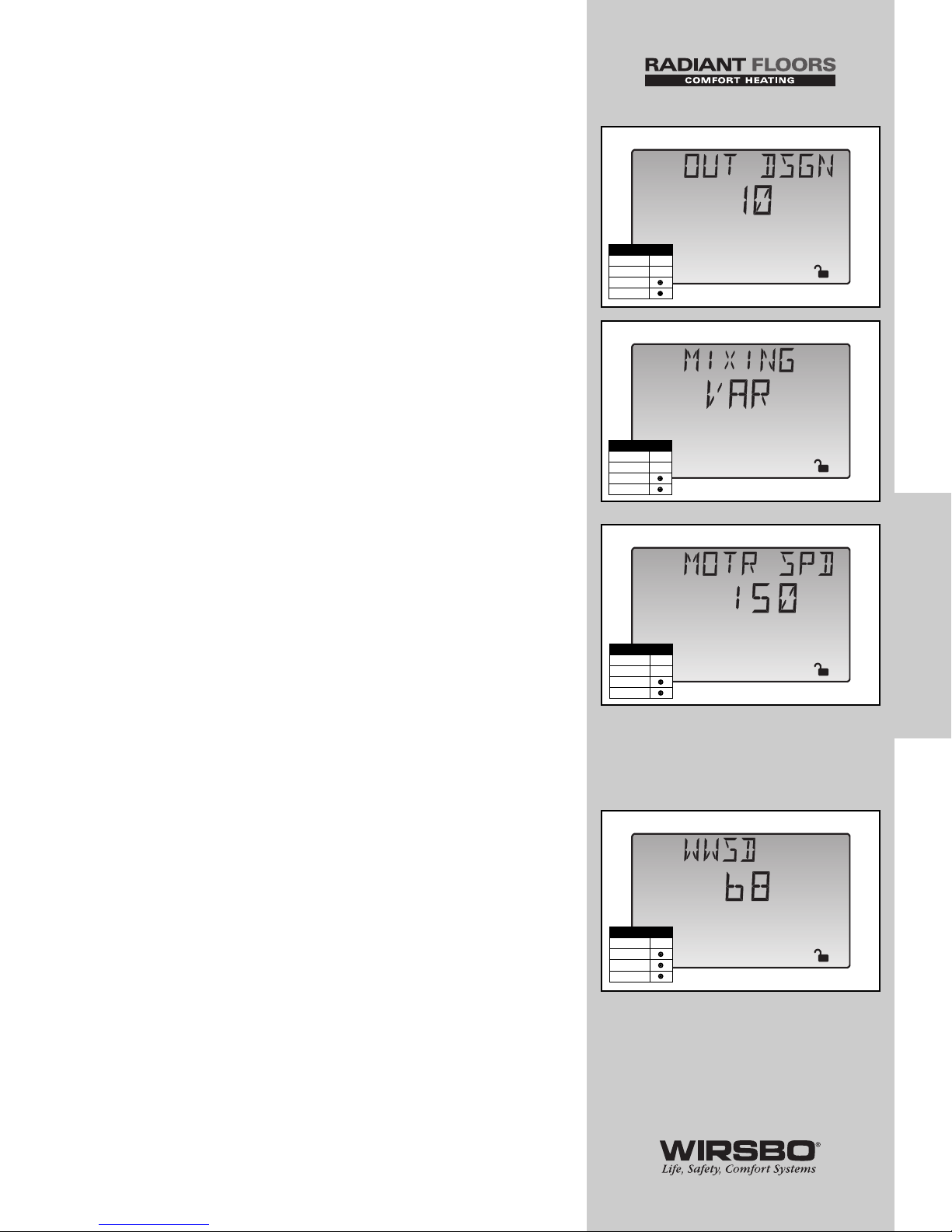
OUTDOOR DESIGN (OUT DSGN) (See fig. ee)
1) Go to OUT DSGN item field in Adjust Menu
2) Set to the outdoor design temperature used in the heat-loss
calculation
RANGE: -60 to 50°F (-51 to 10°C)
DEFAULT: 10°F (-12°C)
MIXING DEVICE SELECTION (MIXING) (See fig. ff)
1) Go to MIXING item field in Adjust Menu
2) Set the type of mixing device used (floating action mixing
valve “FLOT” or variable speed injection pump “VAR”)
RANGE: FLOT (Floating), VAR (Variable Speed)
DEFAULT: VAR
MOTOR SPEED (MOTR SPD) (See fig. gg)
NOTE: For a Floating Action Valve Mixing Device only.
1) Go to MIXING item field in Adjust Menu
2) Set MIXING to FLOT
3) Go to MOTR SPD item field in Adjust Menu
4) Set the time the actuating motor requires to operate from
fully closed to fully open
RANGE: 30 to 230 sec
DEFAULT: 150 sec
WARM WEATHER SHUT DOWN (WWSD)
(See fig. hh)
The control enters into WWSD when slab and outdoor
temperatures exceed MELTING temperature by more than
1.5°F (1°C).
1) Go to WWSD item field in the Adjust Menu
2) Set to an outdoor temperature at which the system no
longer needs to heat the zone to maintain a comfortable
temperature inside
RANGE: 35 to 100°F, OFF (2 to 38°C, OFF)
DEFAULT: 68°F (21°C)
53
PROGRAMMING
PROGRAMMING - Step 1 - Programming the Control
Adjust
ff
Access Level
LTD
USER
INST
ADV
Adjust
o
F
ee
Access Level
LTD
USER
INST
ADV
Adjust
sec
gg
Access Level
LTD
USER
INST
ADV
Adjust
o
F
hh
Access Level
LTD
USER
INST
ADV
Page 56
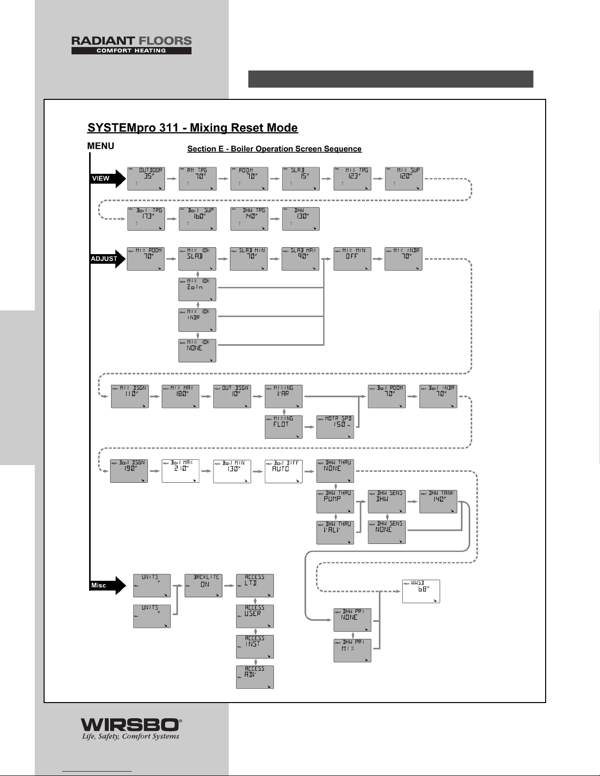
PROGRAMMING
THE
“ADJUST” MENU
E. BOILER OPERATION
54
PROGRAMMING
PROGRAMMING - Step 1 - Programming the Control
Page 57
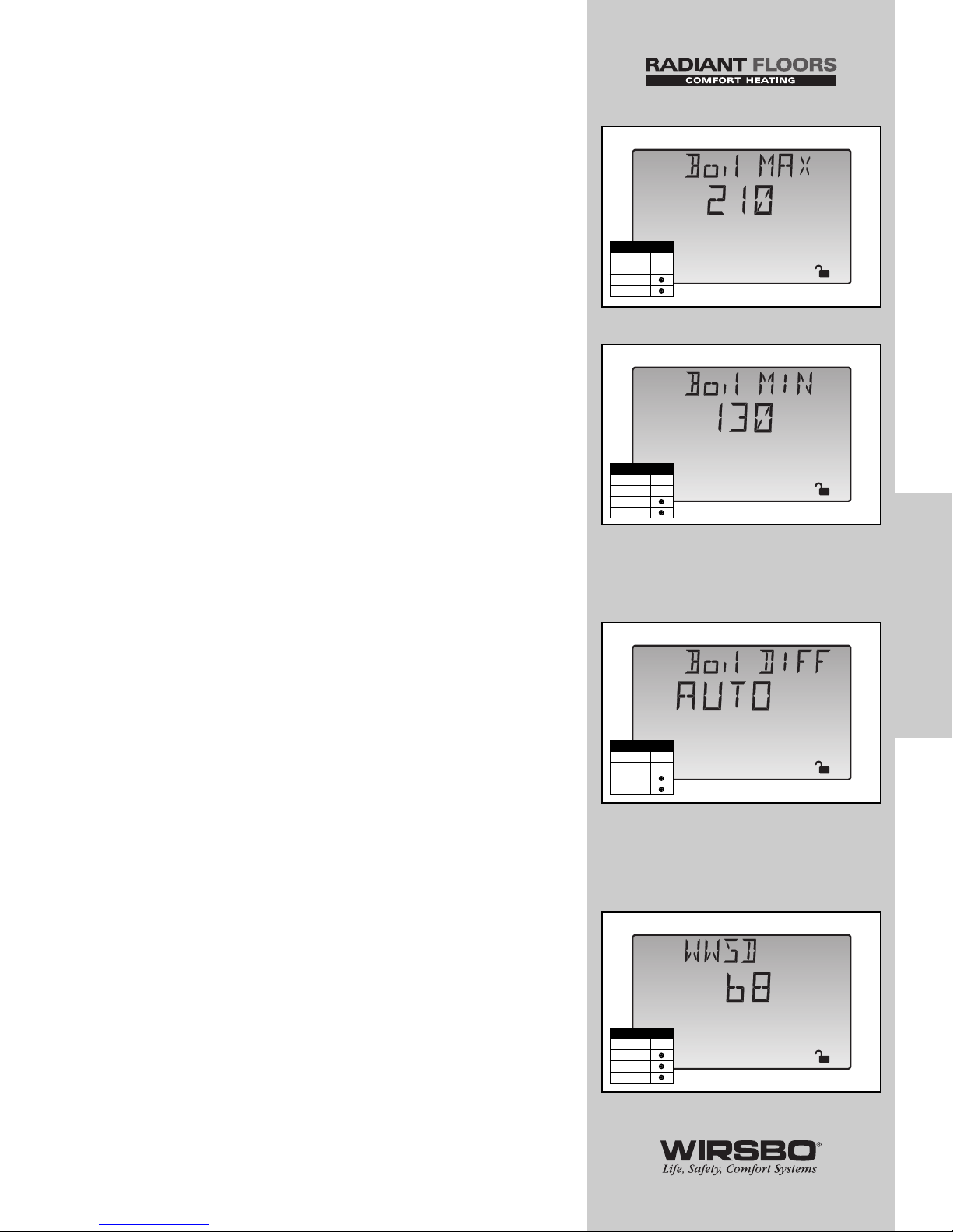
BOILER MAXIMUM (Boil MAX) (See fig. ii)
1) Go to Boil MAX item field in Adjust Menu
2) Set to the highest water temperature the boiler is allowed
to use as a Boil TRG temperature (Refer to the boiler
manufacturer’s literature)
RANGE: 120 to 225°F, OFF (49 to 107°C, OFF)
DEFAULT: 210°F (99°C)
BOILER MINIMUM (Boil MIN) (See fig. jj)
1) Go to Boil MIN item field in Adjust Menu
2) Set to the lowest water temperature that the control is
allowed to use as a boiler target temperature (Refer to the
boiler manufacturer’s literature)
RANGE: OFF, 80 to 180°F (OFF, 27 to 82°C)
DEFAULT: 130°F (54°C)
NOTE: If boiler is designed for condensing
operation, set the Boil MIN adjustment to OFF.
DIFFERENTIAL (Boil DIFF) (See fig. kk)
An on/off heat source such as a boiler must be operated
with a differential to prevent short cycling. With the
SYSTEMpro 311, it has either a fixed or automatic differential
setting that may be selected.
1) Go to Boil DIFF item field in Adjust Menu
2) Select Auto (for automatic operation) or enter a differential
temperature manually
RANGE: AUTO, 2 to 42°F (AUTO, 1 to 23°C)
DEFAULT: AUTO
WARM WEATHER SHUT DOWN (WWSD)
(See fig. ll)
The control enters into WWSD when slab and outdoor
temperatures exceed MELTING temperature by more than
1.5°F (1°C).
1) Go to WWSD item field in the Adjust Menu
2) Set to an outdoor temperature at which the system no
longer needs to heat the zone to maintain a comfortable
temperature inside
RANGE: 35 to 100°F, OFF (2 to 38°C, OFF)
DEFAULT: 68°F (21°C)
55
PROGRAMMING
PROGRAMMING - Step 1 - Programming the Control
Adjust
o
F
ll
Adjust
o
F
ii
Access Level
LTD
USER
INST
ADV
Access Level
LTD
USER
INST
ADV
Adjust
o
F
jj
Adjust
kk
Access Level
LTD
USER
INST
ADV
Access Level
LTD
USER
INST
ADV
Page 58

PROGRAMMING - STEP 2
TEST SEQUENCE
The SYSTEMpro 311 has a built-in test routine which is used
to test the main control functions. The control monitors the
sensors and displays an error message whenever a fault is
found. See Appendix IV (page 98) for a list of the
SYSTEMpro's error messages and possible causes. When the
test button is pressed, the test light is turned on. The outputs
and relays are tested in the following sequence:
• Each step in the test sequence lasts 10 seconds.
• During the test routine, the test sequence is paused by
pressing the test button
• While paused, the control displays the testing step as well as
the abbreviation PAUS
• If the Test button is not pressed again for 5 minutes while the
test sequence is paused, the control exits the entire test
routine
• If the test sequence is paused, the Test button can be pressed
again to advance to the next step (this can also be used to
rapidly advance through the test sequence)
• To reach the desired step, repeatedly press and release the
Test button until the appropriate device and segment in the
display turn on
Step 1
• If FLOT is selected in MIXING item, mixing valve is run fully
open
• If VAR is selected in MIXING item, injection pump is ramped
up
over 10 seconds to 100%
Step 2
• If FLOT is selected in MIXING item, mixing valve is run fully
closed
• If VAR is selected in MIXING item, injection pump is ramped
down
over 10 seconds
Step 3
• The mixing system pump (P1) is turned on for 10 seconds
and then shuts off
NOTE: The control can only be paused
in step 3 if there is a mixing demand.
Step 4
• The boiler demand pump (P7) is turned on for 10 seconds
and then shuts off
NOTE: The control can only be paused
in Step 4 if there is a boiler demand.
56
PROGRAMMING
PROGRAMMING - PROGRAMMING - Step 2 - Test Sequence
NOTE:
Before you begin testing,
all appropriate settings must
be entered into the control
using the LCD screen. If
you are unfamiliar with the
theory behind a hydronic
radiant heating system, please
refer to the Control Function
Overview for more help.
Page 59
Step 5
• The primary pump (P3) is turned on and remains on
Step 6
• The Boiler contact is turned on for 10 seconds
• After 10 seconds, the Boiler and Boil P3 contacts are shut off
NOTE: The control can only be paused in
step 6 if there is a boiler or mixing demand.
Step 7
• If PUMP is selected in DHW THRU item, DHW P6/Vlv contact
is closed for 10 seconds
• If VLV is selected in DHW THRU item, DHW P6/Vlv and
Boil P3 contacts are closed for 10 seconds.
• If NONE is selected in DHW THRU item, N/A is displayed
in the LCD
NOTE: The control can only be paused
in step 7 if there is a DHW demand.
Step 8
• After test sequence is completed, the word COMPLETE
is displayed for 1 second and control resumes normal operation
MAX HEAT (See fig. a & b)
The SYSTEMpro 311 has a function called Max Heat. In this
mode, the control turns on and operates the system up to the
maximum set temperatures, and the mixing device at the set
percentage, as long as there is a demand for heat.
• This mode may be used for running all circulators during
system start-up in order to purge air from the piping
• Once started, control continues to operate in MAX HEAT
mode for up to 24 hours or until either the Item, Menu or Test
button is pressed
• To enable the Max Heat feature, use the following procedure:
1) Press and hold the Test button for more than 3 seconds.
At this point, control displays the words MAX HEAT and the
word NO
2) Using the up and down buttons, select the word YES. After
3 seconds, the control flashes the word MANUAL and the
number 100. This number represents the desired output
from the mixing device
3) Set desired output of mixing device by using the up and/or
down buttons on the control.
4) To cancel Max Heat mode, press either Item, Menu, or
Test button
5) Once Max Heat mode ends or is cancelled, control resumes
normal operation
57
PROGRAMMING
PROGRAMMING - Step 2 - Test Sequence
%
View
1
a
%
View
1
b
Page 60

CONTROL
FUNCTION
OVERVIEW
TABLE OF CONTENTS
Section A – General .............................................................. 59
Section B – Boiler / High Temp Zones .......................... 60-62
Section B1 – General ................................ 60-62
Section B2 – Boiler Demands ........................ 62
Section C – Domestic Hot Water (DHW) ...................... 63-66
Section C1 – General ................................ 63-64
Section C2 – DHW Priority ........................ 65-66
Section D – Mixing Zones .............................................. 67-71
Section D1 – General ................................ 67-69
Section D2 – Mixing Devices.................... 69-70
Section D3 – Mixing Demands ................ 70-71
Section E – Snow Melting .............................................. 72-79
Section E1 – General.................................. 72-75
Section E2 – With Slab Sensor ................ 76-77
Section E3 – Without Slab Sensor .......... 77-78
Section E4 – Snow Melt Enable .............. 78-79
Section F – Boiler Operation .......................................... 80-81
Section F1 – Boiler Supply Sensor.......... 80-81
Section G – Troubleshooting .......................................... 82-83
POWERING UP THE CONTROL
When the SYSTEMpro 311 is powered up:
1) It displays the control type number in the LCD for 2 seconds
2) It displays the software version for another 2 seconds
3) It defaults to normal operating mode by displaying current
outdoor air temperature
58
CONTROL FUNCTION
OVERVIEW
CONTROL FUNCTION OVERVIEW - CONTROL FUNCTION OVERVIEW - Table of Contents
Page 61
CONTROL FUNCTION
OVERVIEW - SECTION A
GENERAL
This section explains the operation of each menu function on
the SYSTEMpro 311 in order of control area.
WARM WEATHER SHUT DOWN (WWSD)
(See fig. a)
• When the outdoor air temperature rises above WWSD
setting, the SYSTEMpro 311 turns on the LCD's WWSD
pointer
• When control is in Warm Weather Shut Down, Mix Demand
and Boiler Demand pointers are still displayed if there is a
demand
NOTE: The control does not operate the heating
system to satisfy Mix or Boiler demands. The control
will respond to a DHW demand and operates as
described in Section C.
EXERCISING
• The SYSTEMpro 311 has a built-in pump and valve
exercising function
• If a pump or valve output on the control has not been
operated at least once during every exercising period, the
control turns on the output for 10 seconds
• Exercising reduces possibility of a pump or valve seizing
during a long period of inactivity
NOTE: If a mixing valve is being used as the mixing
device, the SYSTEMpro 311 makes sure the valve
operates over its entire range at least once each
exercising period (every 70 hours). The exercising
function will not work if power to the control,
pumps or valves is disconnected.
59
CONTROL FUNCTION
OVERVIEW
CONTROL FUNCTION OVERVIEW - Section A - General
Adjust
o
F
a
Access Level
LTD
USER
INST
ADV
Page 62
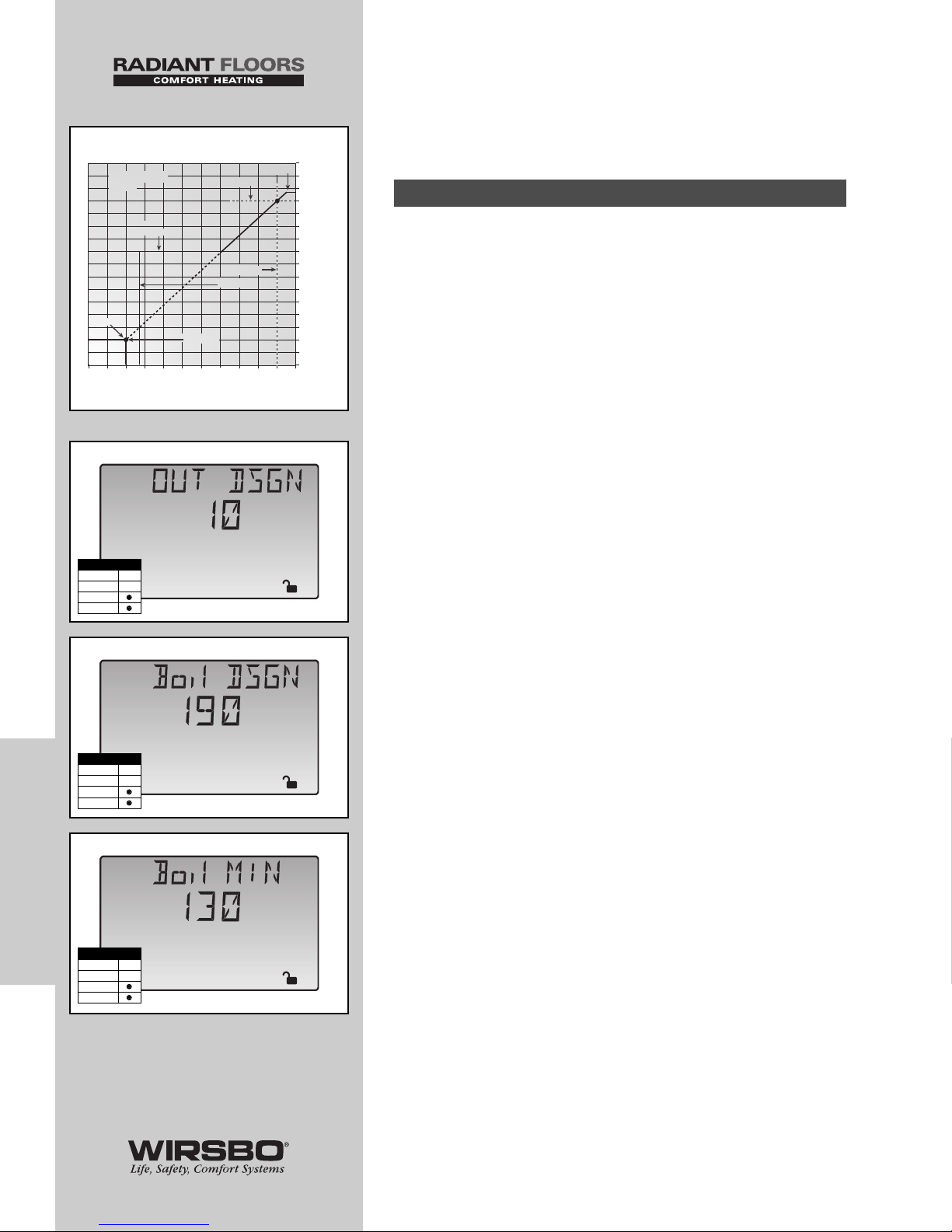
CONTROL FUNCTION
OVERVIEW - SECTION B
BOILER / HIGH TEMP ZONES
The SYSTEMpro 311 can provide a reset supply water
temperature from the primary boiler loop to high temp mix
loops. Boiler zones piped into the primary loop will receive the
same water temperature as the current boiler supply
temperature. The boiler supply temperature is automatically
adjusted by the SYSTEMpro 311 based on the following
information you must enter into the control's Adjust Menu.
NOTE: The SYSTEMpro 311 will automatically
calculate a reset ratio based on the data you input.
OUTDOOR DESIGN (OUT DSGN) (See fig. a)
• The OUT DSGN is set to the outdoor design temperature
used on the heat-loss analysis for the project
BOILER DESIGN (Boil DSGN) (See fig. b)
• The Boil DSGN temperature is the temperature the supply
water must be heated to heat the boiler zones when the
outdoor air is at the OUT DSGN temperature
BOILER MINIMUM (Boil MIN) (See fig. c)
• The Boil MIN is the lowest water temperature that the control
is allowed to use as a boiler target temperature (Refer to the
boiler manufacturer’s literature)
• During mild conditions, if the control calculates a Boil TRG
temperature below the Boil MIN setting, the Boil TRG
temperature adjusts to at least the Boil MIN setting
NOTE: During this condition, if the boiler is
operating near the Boil MIN setting, the Minimum
pointer turns on while the Boil TRG or Boil SUP
temperature is viewed
• If the installed boiler is designed for condensing operation,
set the Boil MIN adjustment to OFF
Section B1: General
60
CONTROL FUNCTION
OVERVIEW
CONTROL FUNCTION OVERVIEW - CONTROL FUNCTION OVERVIEW - Section B - Boiler / High Temp Zones
Boil MAX
Boil DSGN
OUT DSGN
WWSD
Boil ROOM
210
(99)
190
(88)
170
(77)
150
(66)
130
(54)
110
(43)
90
(32)
70
(21)
50°F
(10°C)
-20
(-29)
0
(-18)
20
(-7)
40
(5)
60
(16)
80
(27)
Outdoor Air Temperature
Su
pp
l
y
Water Tem
p
erature
Boiler Reset
Ratio
Boil MIN
Boil INDR
Adjust
o
F
a
Adjust
o
F
b
Adjust
o
F
c
Access Level
LTD
USER
INST
ADV
Access Level
LTD
USER
INST
ADV
Access Level
LTD
USER
INST
ADV
Page 63
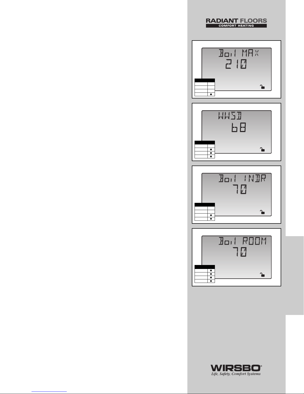
BOILER MAXIMUM (Boil MAX) (See fig. d)
• The Boil MAX is the highest water temperature the control is
allowed to use as a Boil TRG temperature
• At no time does the control operate the boiler above 248°F
(120°C).
NOTE: If the control calculates target Boil MAX
and the Boil SUP temperature is near the Boil MAX
temperature, the Maximum pointer turns on while
the Boil TRG or the Boil SUP temperature is viewed.
WARM WEATHER SHUT DOWN (WWSD)
(See fig. e)
• When the outdoor air temperature rises above WWSD
setting, the SYSTEMpro 311 turns on the LCD's WWSD
pointer
• When control is in Warm Weather Shut Down, Mix Demand
and Boiler Demand pointers are displayed if there is a
demand
NOTE: The control does not operate the heating
system to satisfy Mix or Boiler demands. The control
will respond to a DHW demand and operates as
described in Section C.
BOILER INDOOR (Boil INDR) (See fig. f)
• Boil INDR is the room temperature used in original building
heat-loss calculations
• Setting establishes the beginning of the reset ratio for the
boiler zones
BOILER ROOM (Boil ROOM) (See fig. g)
• The Boil ROOM is the desired room temperature for the
boiler zones
• This setting provides a parallel shift of the reset ratio
NOTE: The room temperature desired by the
occupants is often different from the designed indoor
temperature (Boil INDR). If the room temperature is
not correct, adjusting Boil ROOM setting increases or
decreases amount of heat available to the building.
61
CONTROL FUNCTION
OVERVIEW
CONTROL FUNCTION OVERVIEW - Section B - Boiler / High Temp Zones
Adjust
o
F
d
Adjust
o
F
e
Adjust
o
F
f
Adjust
o
F
g
Access Level
LTD
USER
INST
ADV
Access Level
LTD
USER
INST
ADV
Access Level
LTD
USER
INST
ADV
Access Level
LTD
USER
INST
ADV
Page 64

BOILER DEMAND PUMP (P7) OPERATION
• The boiler demand pump (Boil Dem Pmp P7) contact
(terminals 9 and 10) closes if there is a boiler demand and the
control is not in WWSD
• After boiler demand is removed, the boiler system pump
runs an additional 20 seconds
NOTE: Boiler demand can be an external demand
or a boiler zone control as described in section B2.
EXTERNAL BOILER DEMAND
External boiler demand is generated by applying a voltage
between 24 and 240 VAC across Boil Dem (3) and Com Dem
(4) terminals.
• Once voltage is applied, Boiler Demand pointer is displayed
in the LCD
• If control is not in WWSD, it closes the Boil P3 contact, which
starts the primary pump and closes the Boil Dem Pmp P7
contact, which starts the boiler system pump
• The control turns on the primary pump and boiler system
pump segments in the LCD
• The control calculates a Boil TRG supply temperature, then
fires the boiler (if required) to reach and/or maintain target
supply temperature
BOILER ZONE CONTROL
A tekmar zone control can be used to control the temperature
in the boiler zones connected to the boiler demand pump (P7).
• Connects to SYSTEMpro 311 using Boil ZoIn terminal and
Com terminal (24 and 25)
• Provides its own internal boiler demand to SYSTEMpro 311
NOTE: In this case, there is no need
to provide external boiler demand.
• Can adjust the Boil TRG temperature (if required) to provide
improved building occupant comfort and system performance
Section B2: Boiler Demands
62
CONTROL FUNCTION
OVERVIEW
CONTROL FUNCTION OVERVIEW - CONTROL FUNCTION OVERVIEW - Section B - Boiler / High Temp Zones
Page 65
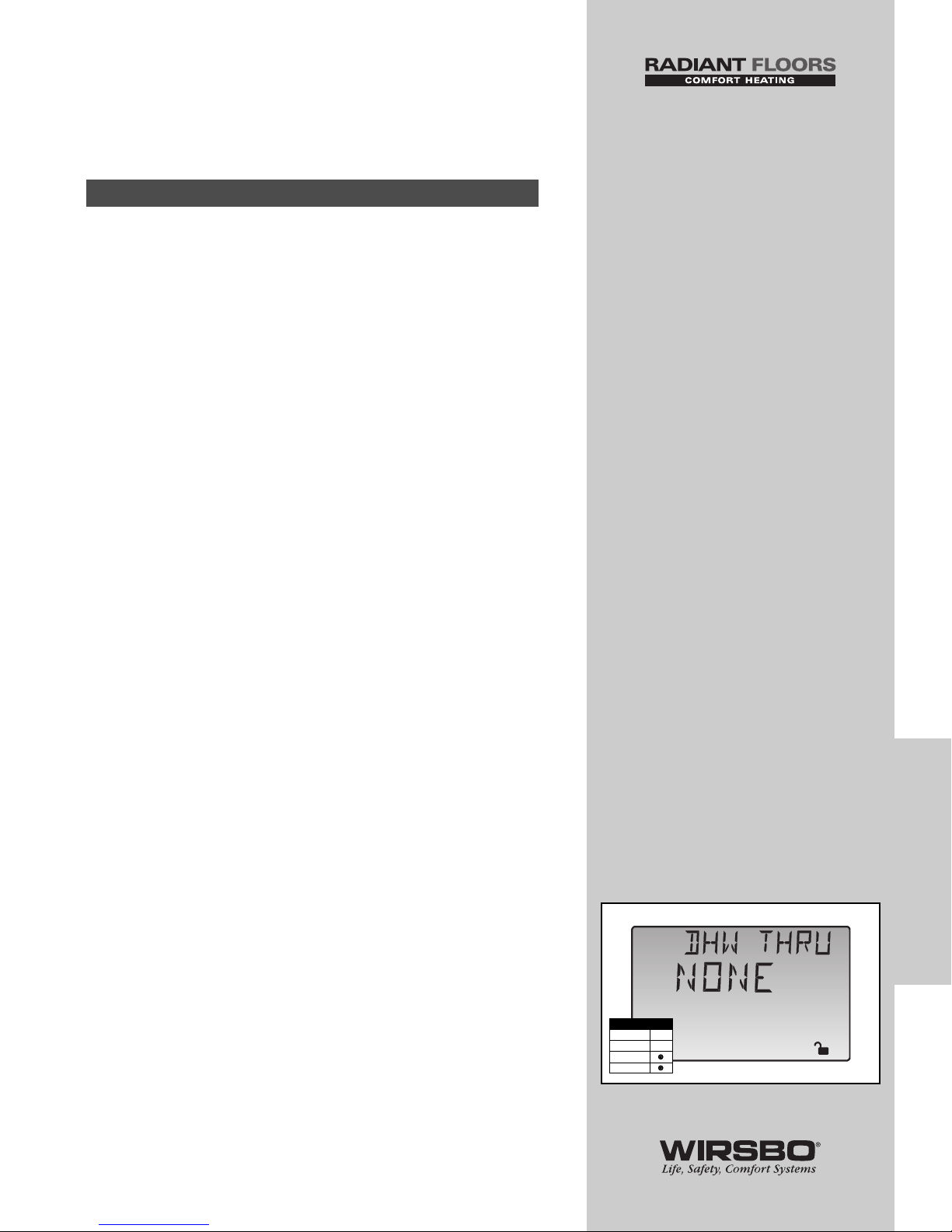
CONTROL FUNCTION
OVERVIEW - SECTION C
DOMESTIC HOT WATER
A DHW demand is generated on the SYSTEMpro 311 by one
of two methods:
1) an external DHW demand from an aquastat
2) an internal demand from a universal sensor
External Demand (Aquastat)
• The SYSTEMpro 311 registers an external demand for DHW
when voltage between 24 and 240 VAC is applied across
DHW Dem and Com Dem terminals (4 and 5)
• A DHW aquastat or setpoint control is used as a switch in the
DHW demand circuit
• Once the control detects a DHW demand, the LCD's DHW
Demand icon turns on and the control operates as described
in section “BOILER TRG DURING DHW GENERATION”
Internal Demand (Universal Sensor)
• If the DHW SENS item is set to DHW, the control looks
for a DHW sensor connected to the DHW S6 and the Com
terminals (27 and 28)
• The DHW TANK setting is used to set the desired indirect
DHW tank temperature
• When the temperature at the DHW sensor drops 3°F (1.5°C)
below DHW TANK setting, the LCD's DHW Demand pointer
turns on and the control operates as described in section
“BOILER TRG DURING DHW GENERATION”
NOTE: An advantage to using the DHW sensor is
that the control can display the current DHW TANK
temperature. Also, SYSTEMpro 311 can control the
DHW temperature with more accuracy compared to
an aquastat.
DHW DEVICE (DHW THRU) (See fig. a)
When the control receives a DHW demand, the sequence
of operation depends on the type of DHW device selected.
The DHW device is selected using the DHW THRU item in the
Adjust Menu.
Section C1: General
63
CONTROL FUNCTION
OVERVIEW
CONTROL FUNCTION OVERVIEW - Section C - Domestic Hot Water
Adjust
a
Access Level
LTD
USER
INST
ADV
Page 66
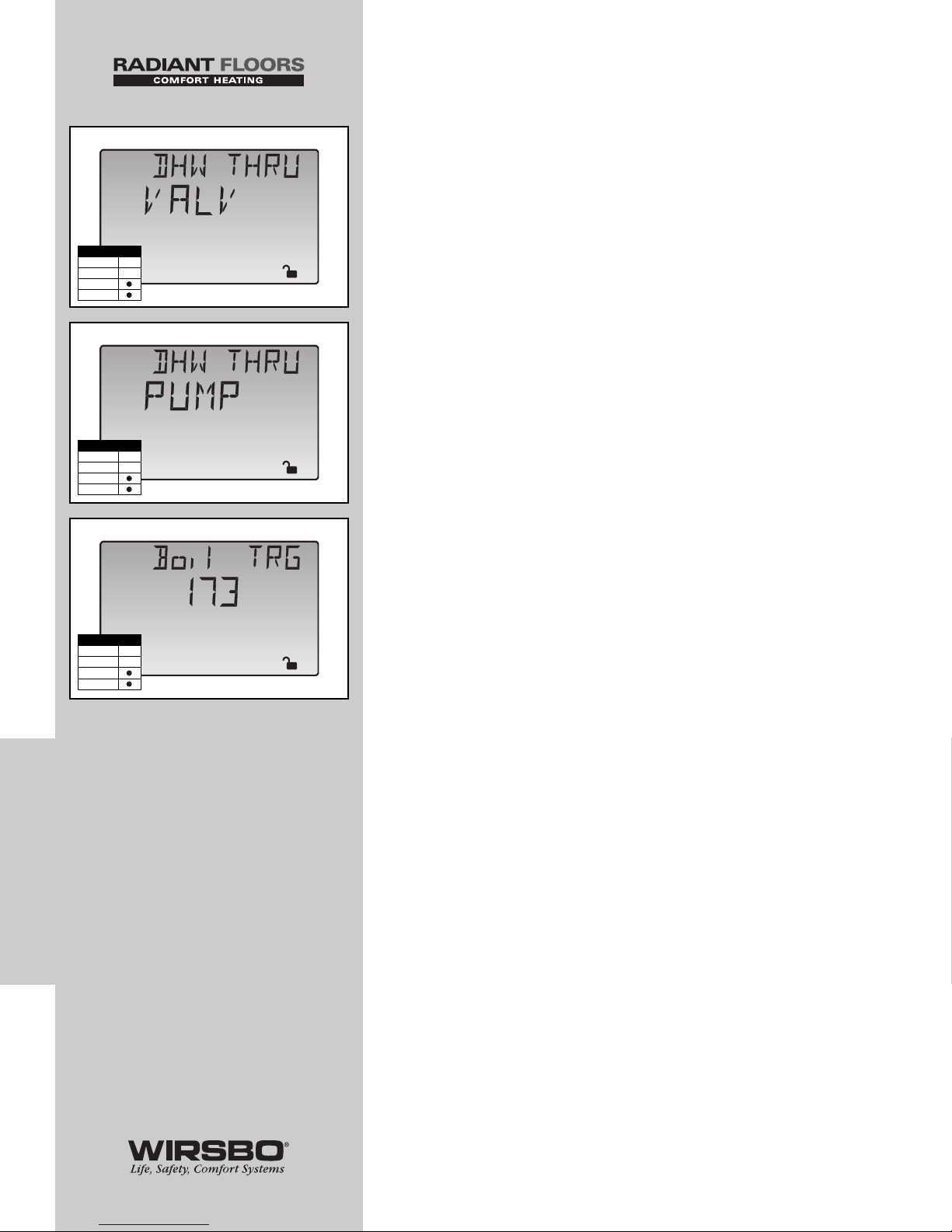
DHW Valve (VALV) (See fig. b)
• If VALV is selected as DHW device and a DHW demand
exists, the control closes the DHW P6/Vlv contact (13 and 14)
and the Boil P3 contact (7 and 8)
• The primary pump provides flow through DHW tank’s heat
exchanger once the DHW valve is opened
• The control operates the Boiler contact to provide a sufficient
boiler supply temperature to DHW tank
DHW Pump (PUMP) (See fig. c)
• If PUMP is selected as the DHW device, the control assumes
the DHW pump provides adequate flow through both the
DHW tank heat exchanger and the boiler
• To provide heat to DHW tank, the control closes DHW P6/Vlv
contact (13 and 14).
• The control operates the Boiler contact to provide sufficient
boiler supply temperature to DHW tank
• If using a primary loop with DHW tank piped in
primary/secondary, select DHW valve
BOILER TARGET DURING DHW GENERATION
(Boil TRG) (See fig. d)
The Boil TRG temperature during DHW operation depends on
whether an external or internal demand is occurring. The
DHW demand then overrides the reset water temperature.
External Demand (Aquastat)
• If the control receives a DHW demand through an external
device such as an aquastat, the Boil TRG temperature is at
least 180°F
Internal Demand (Universal Sensor)
If the control receives a DHW demand from a DHW sensor
connected to the DHW S6 and the Com terminals (27 and 28),
the Boil TRG temperature is at least as hot as the DHW TANK
setting plus 40°F (22°C).
64
CONTROL FUNCTION
OVERVIEW
CONTROL FUNCTION OVERVIEW - CONTROL FUNCTION OVERVIEW - Section C - Domestic Hot Water
Adjust
b
Adjust
c
%
View
o
F
1
d
Access Level
LTD
USER
INST
ADV
Access Level
LTD
USER
INST
ADV
Access Level
LTD
USER
INST
ADV
Page 67
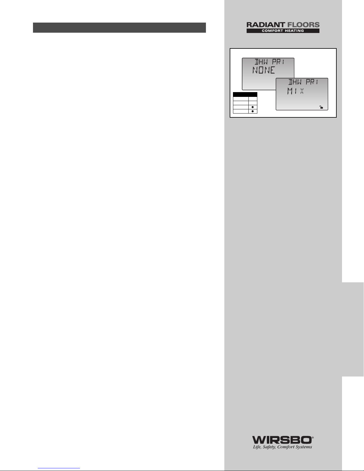
Often, it is desirable to limit or stop the flow of heat to the
heating system when the DHW tank calls for heat. This allows
for faster recovery of the DHW tank. The control has several
features that it can use when dealing with DHW priority. The
features available depend on the type of DHW device being
used and the type of DHW demand the control receives.
Mixing Priority (DHW PRI = MIX) (See fig. e)
It can be set up so the DHW tank has priority over mixing
zones. In this case:
• The mixing device is throttled back on a call for DHW
• The mixing system pump (P1) continues to operate based on
the mix demand
• The reduction of the mixing device's output directs more
heat to the DHW tank
NOTE: Boiler zones will continue
to operate without change.
DHW PRIORITY OVERRIDE
To prevent the building from cooling off too much or from a
potential freeze up during DHW priority, the control limits the
amount of time for DHW priority.
• As the outdoor air temperature becomes colder, the length of
time that the control provides DHW priority is reduced
• Once the allowed time for priority has elapsed, the control
overrides the DHW priority and operates DHW and heating
simultaneously
CONDITIONAL DHW PRIORITY
During DHW generation, if the boiler supply temperature
holds at or above the required temperature the boiler has
enough capacity for DHW and possibly the heating system.
• DHW and heating occurs simultaneously as long as the
boiler supply temperature is maintained near its target
Section C2: DHW Priority
65
CONTROL FUNCTION
OVERVIEW
CONTROL FUNCTION OVERVIEW - Section C - Domestic Hot Water
Adjust
e
Access Level
LTD
USER
INST
ADV
Adjust
Page 68

DHW POST PURGE
After DHW demand is removed, control performs a purge on
the boiler.
• Control shuts off boiler and continues to operate either the
DHW pump or DHW valve and primary pump (P3)
• Control purges residual heat from boiler into the DHW tank
• Control continues purge for a maximum of four minutes or
until boiler supply temperature drops 20°F (11°C) below
DHW Boil TRG temperature
• Control stops purge if boiler supply temperature drops
below current Boil TRG temperature
DHW MIXING PURGE
After DHW operation, the boiler is extremely hot, while heating
zones may have cooled off considerably after being off for a
period of time.
• To avoid thermally shocking the boiler after DHW priority, the
control shuts off the boiler, but continues to operate the
DHW while restarting the heating system
• Above step allows some of the DHW return water to mix with
the cool return water from the zones and temper the boiler
return water
66
CONTROL FUNCTION
OVERVIEW
CONTROL FUNCTION OVERVIEW - CONTROL FUNCTION OVERVIEW - Section C - Domestic Hot Water
Page 69
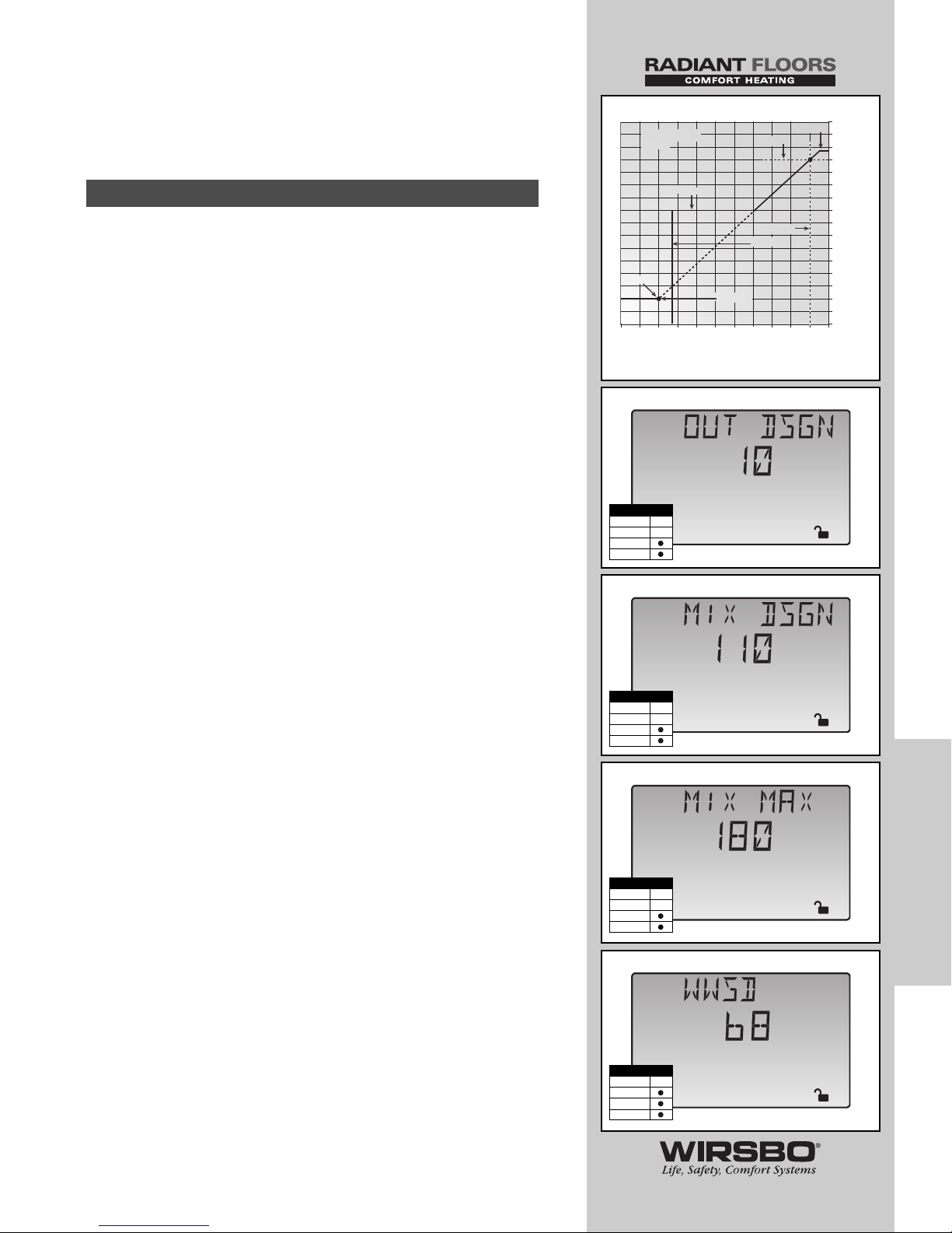
CONTROL FUNCTION
OVERVIEW - SECTION D
MIXING ZONES
The SYSTEMpro 311 can provide a reset supply water
temperature from the primary boiler loop to a secondary
mixed loop via a variable speed injection mixing or a floating
action valve. The mixing supply temperature is determined
using a reset ratio. In order for the control to set up a reset
ratio, the following information must be entered into the
Adjust Menu.
OUTDOOR DESIGN (OUT DSGN) (See fig. a)
• OUT DSGN is the outdoor air temperature used when doing
heat-loss calculations for the building
MIXING DESIGN (MIX DSGN) (See fig. b)
• MIX DSGN temperature is the supply water temperature
required to heat mixing zones when the outdoor
temperature is at OUT DSGN temperature
MIXING MAXIMUM (MIX MAX) (See fig. c)
• MIX MAX sets highest water temperature control is allowed
to use as MIX TRG temperature
• If control calculates target MIX MAX setting, and MIX SUP
temperature is near MIX MAX temperature, the LCD's
Maximum pointer turns on while either the MIX TRG
temperature or the MIX SUP temperature is viewed
WARM WEATHER SHUT DOWN (WWSD)
(See fig. d)
• When outdoor air temperature rises above WWSD setting,
the SYSTEMpro 311 goes into WWSD and turns on the LCD's
WWSD pointer
• When control is in WWSD, Mix Demand and Boiler Demand
pointers are displayed if there is a demand
NOTE: The control does not operate the heating
system to satisfy Mix or Boiler demands. The control
will respond to a DHW demand and operates as
described in Section C.
Section D1: General
67
CONTROL FUNCTION
OVERVIEW
CONTROL FUNCTION OVERVIEW - Section D - Mixing Zones
Adjust
o
F
a
Adjust
o
F
b
Adjust
o
F
c
Access Level
LTD
USER
INST
ADV
Access Level
LTD
USER
INST
ADV
Access Level
LTD
USER
INST
ADV
Adjust
o
F
d
Access Level
LTD
USER
INST
ADV
Mix MAX
Mix DSGN
OUT DSGN
WWSD
Mix ROOM
210
(99)
190
(88)
170
(77)
150
(66)
130
(54)
110
(43)
90
(32)
70
(21)
50°F
(10°C)
-20
(-29)
0
(-18)
20
(-7)
40
(5)
60
(16)
80
(27)
Outdoor Air Temperature
Su
pp
l
y
Water Tem
p
erature
Mixing Reset
Ratio
Mix MIN
Mix INDR
Page 70
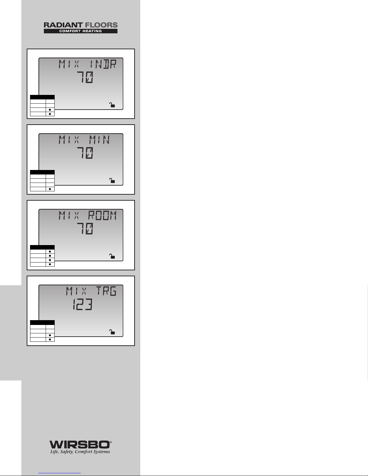
MIXING INDOOR (MIX INDR) (See fig. e)
• MIX INDR is room temperature used in original heat-loss
calculations for the building
• Setting establishes beginning of reset ratio for mixing zones
MIXING MINIMUM (MIX MIN) (See fig. f)
• MIX MIN is lowest temperature control is allowed to use as
MIX TRG temperature.
• During mild conditions, if control calculates a MIX TRG
temperature below MIX MIN setting, MIX TRG temperature
is adjusted to match MIX MIN setting
• If mixing supply temperature is near MIX MIN setting, the
LCD's Minimum pointer turns on (when MIX TRG or MIX
SUP temperature is being viewed)
• If using an indoor sensor and control is operating at MIX MIN
temperature, the mixing system pump (P1) is cycled using
Pulse Width Modulation (PWM) with a 15 minute cycle length
• The Control provides an average supply water temperature
to the mixing system by cycling the mixing system pump
(P1) and controlling the flow of supply water (average
temperature is equal to the original MIX TRG)
NOTE: This step minimizes overheating the zone
while control is operating at MIX MIN temperature.
MIXING ROOM (MIX ROOM) (See fig. g)
• MIX ROOM is desired room temperature for mixing zones
NOTE: There is only a ±3°F (±1°C)
adjustment in the LTD Access Level.
• Provides a parallel shift of reset ratio
NOTE: Room temperature desired by occupants is
often different from designed indoor temperature
(MIX INDR). If room temperature is not correct,
adjusting MIX ROOM setting increases or decreases
the amount of heat available to the building.
MIXING TARGET TEMPERATURE (MIX TRG)
(See fig. h)
• MIX TRG temperature is determined from reset ratio settings
and outdoor air temperature
• The Control displays the temperature it is currently trying to
maintain as mixing supply temperature
• If control does not presently have a requirement for heat,
it displays “---“ in LCD
68
CONTROL FUNCTION
OVERVIEW
CONTROL FUNCTION OVERVIEW - CONTROL FUNCTION OVERVIEW - Section D - Mixing Zones
Adjust
o
F
e
Adjust
o
F
f
Adjust
o
F
g
%
View
o
F
1
h
Access Level
LTD
USER
INST
ADV
Access Level
LTD
USER
INST
ADV
Access Level
LTD
USER
INST
ADV
Access Level
LTD
USER
INST
ADV
Page 71
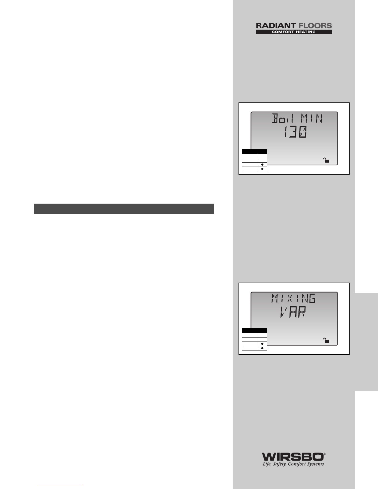
MIXING PUMP (P1) OPERATION
• Mixing pump (P1) contact (terminals 11 and 12) closes
whenever there is mixing demand and the SYSTEMpro 311
is not in WWSD
• After mixing demand is removed, Mixing Pmp P1 contact
remains closed for 20 seconds
• During WWSD, the mixing pump (P1) is operated based on
EXERCISE function
BOILER MINIMUM PROTECTION (Boil MIN)
(See fig. i)
• The SYSTEMpro 311 can offer boiler protection from
cold mixing system return water temperature entering the
boiler while firing. This helps reduce possible flue gas
condensation.
• If boiler water temperature is cooler than Boil MIN setting
while boiler is firing, control reduces output from mixing
device (limits amount of cool return water to boiler and
allows boiler water temperature to recover)
MIXING DEVICE SELECTION (MIXING)
• The SYSTEMpro 311 can supply a lower water temperature
to part of the heating system by varying the speed of an
injection pump or modulating a mixing valve.
• This selection is made under the MIXING item in the Adjust
Menu.
VARIABLE SPEED INJECTION (VAR) (See fig. j)
• A standard wet rotor circulator is connected to the
SYSTEMpro 311 on Cls/P4 terminal (19)
• Control increases or decreases power output to circulator
when there is mix demand
• Circulator speed varies to maintain correct mixed supply
water temperature at mix supply sensor
• For correct sizing and piping of variable speed injection
driven circulator, refer to essay Appendix I, Variable Speed
Injection Mixing on page 85.
• A visual indication of current variable speed output is
displayed in the LCD as a segmented bar graph. Two small
indicators at the top of the graph indicate whether the output
is increasing or decreasing.
Section D2: Mixing Devices
69
CONTROL FUNCTION
OVERVIEW
CONTROL FUNCTION OVERVIEW - Section D - Mixing Zones
Adjust
o
F
i
Adjust
j
Access Level
LTD
USER
INST
ADV
Access Level
LTD
USER
INST
ADV
Page 72
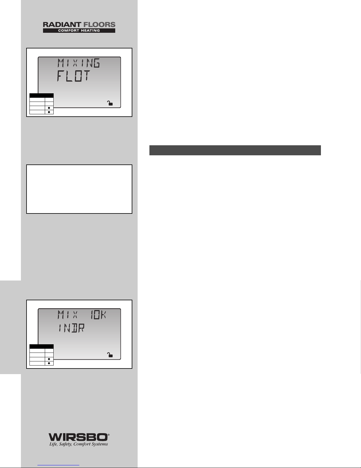
FLOATING ACTION (FLOT) (See fig. k)
• A floating action actuator motor is connected to control on
Opn and Cls/P4 terminals (18 and 19)
• The control pulses actuator motor open or closed to
maintain correct supply water temperature at mix supply
sensor during mix demand
• The mixing valve actuator can be connected to a 2-way,
3-way or 4-way valve
• A visual indication as to whether control is currently opening
or closing the mixing valve is displayed in the LCD with the
words Open and Close (also, a visual indication of the valve's
current position is displayed in the form of a segmented bar
graph)
EXTERNAL MIXING DEMAND (See fig. l)
An external mixing demand allows use of a conventional
thermostat system for zoning. Demand is generated by
applying a voltage between 24 and 240 VAC across the Mix
Demand terminals (1 and 2).
• Once voltage is applied, the Mix Demand pointer is
displayed in the LCD
• If the SYSTEMpro 311 is not in WWSD, it closes the Mixing
Pmp P1 contact
• The Mixing system pump segment is displayed in the LCD
• Control calculates a MIX TRG temperature based on outdoor
air temperature and settings
• If required, control operates Boiler contact (as described in
Section B2, page. 62) to provide heat to mixing device
10K INDOOR SENSOR (MIX 10K = INDR)
(See fig. l)
Set MIX 10K item to INDR to add an indoor sensor that offers
temperature control of a single zone mixing system. The
indoor sensor is connected to Com and Mix 10K terminals
(20 and 21). Power must also be applied to Mix Demand
terminals (1 and 2).
• With indoor sensor connected, control can sense the actual
room temperature
• Using this information, the control offers more constant
water flow through mixing system
• Indoor feedback fine-tunes supply water temperature in
mixing system to prevent overheating or underheating
NOTE: To adjust room temperature for the mixing
zone, use MIX ROOM setting in the Adjust Menu.
Section D3: Mixing Demands
70
CONTROL FUNCTION
OVERVIEW
CONTROL FUNCTION OVERVIEW - CONTROL FUNCTION OVERVIEW - Section D - Mixing Zones
Adjust
k
Adjust
l
Access Level
LTD
USER
INST
ADV
Access Level
LTD
USER
INST
ADV
NOTE: If connecting a Wirsbo
thermostat (WT1 or WT2) directly
to the Mix Demand terminals,
refer to Mixing Demand with
Wirsbo Thermostat on page 23.
Page 73
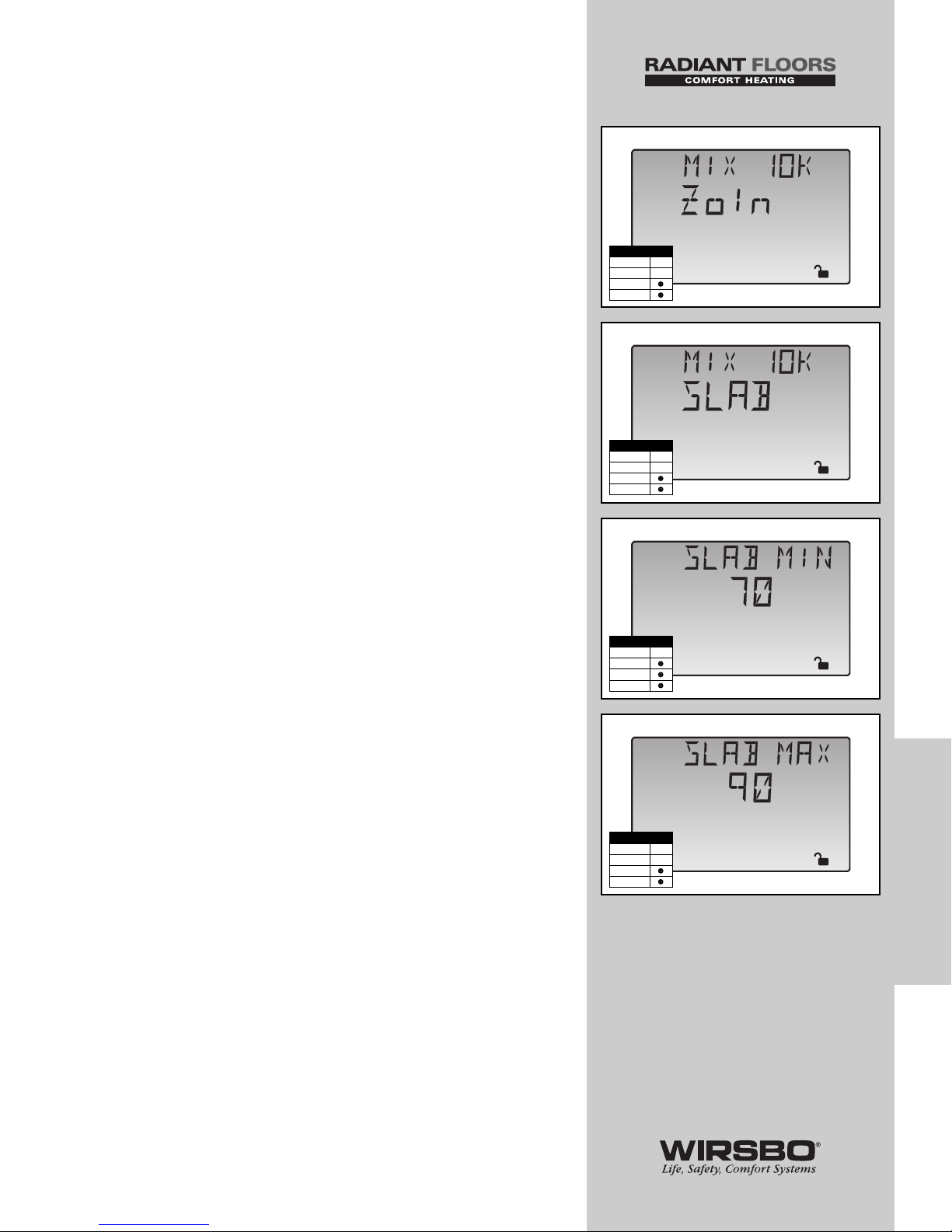
10K ZONE CONTROL (MIX 10K = ZoIn)
(See fig. m)
Set MIX 10K item to ZoIn to add indoor temperature feedback
control of multiple mixing zones
• Control of mixing zones can be provided by connecting a
tekmar zone control to the SYSTEMpro 311
• The zone control provides its own internal mix demand to
the SYSTEMpro 311 control
NOTE: In this case, there is no need to provide
an external mix demand. The zone control is capable
of automatically adjusting the MIX TRG temperature
to improve building occupant comfort and
system performance.
10K SLAB SENSOR (MIX 10K = SLAB) (See fig. n)
Set the MIX 10K item to SLAB to add a slab sensor for
temperature control of a single zone mixing system. Power
must be applied to the Mix Demand terminals (1 and 2).
• SYSTEMpro 311 can use a slab sensor to control the actual
slab temperature
• Slab sensor is placed in the slab and connected to Com and
Mix 10K terminals (20 and 21)
• With slab sensor connected, the control will limit the mixing
supply temperature to keep the slab sensor between the
SLAB MIN and SLAB MAX settings
Slab Minimum (SLAB MIN) (See fig. o)
• SLAB MIN sets minimum allowed core temperature of slab
as long as the control is not in WWSD
NOTE: Caution should be used when adjusting SLAB
MIN setting as this may lead to overheating of zone
during mild conditions.
Slab Maximum (SLAB MAX) (See fig. p)
• SLAB MAX sets maximum allowed core temperature of slab
NOTE: If slab is to be maintained at a fixed core
temperature, set SLAB MAX and SLAB MIN items
to the same setting.
71
CONTROL FUNCTION
OVERVIEW
CONTROL FUNCTION OVERVIEW - Section D - Mixing Zones
Adjust
m
Adjust
n
Adjust
o
F
o
Adjust
o
F
p
Access Level
LTD
USER
INST
ADV
Access Level
LTD
USER
INST
ADV
Access Level
LTD
USER
INST
ADV
Access Level
LTD
USER
INST
ADV
Page 74
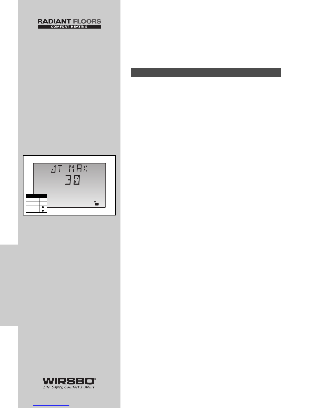
CONTROL FUNCTION
OVERVIEW - SECTION E
SNOW MELTING
(DIP set to Snow Melt)
The SYSTEMpro 311 can control a single zone snow melting
system. To provide the best control of the snow melting
system, control should be equipped with an optional Slab
Sensor (A3060072) and optional Universal Sensor (A3060071)
to measure slab return temperature. These can be purchased
separately or as part of the Snow Melt Enable Kit (A3040039).
NOTE: When operating in snow melt mode,
the Snow Melting/Mixing Reset DIP switch
must be set to Snow Melting position.
SLAB PROTECTION (∆T MAX) (See fig. a)
A mixing device is installed between snow melting slab and
boiler(s) to control rate at which heat is transferred to snow
melting system and to protect slab from thermal stress
damage. The control limits the rate at which heat is applied to
slab through ∆T MAX setting.
• ∆T (delta T) is the temperature difference between slab
supply temperature and slab return temperature
• The rate at which heat is applied to slab can be controlled
and thermal stresses in slab can be minimized by controlling
this temperature difference
• When slab is operating, control ensures slab supply
temperature does not exceed slab return temperature by
more than ∆T MAX setting
NOTE: When control is operating and actual ∆T is
near ∆T MAX, the Maximum pointer can be seen
when viewing the MIX ∆T item in the View Menu.
Section E1: General
72
CONTROL FUNCTION
OVERVIEW
CONTROL FUNCTION OVERVIEW - CONTROL FUNCTION OVERVIEW - Section E - Snow Melting
Adjust
o
F
a
Access Level
LTD
USER
INST
ADV
Page 75
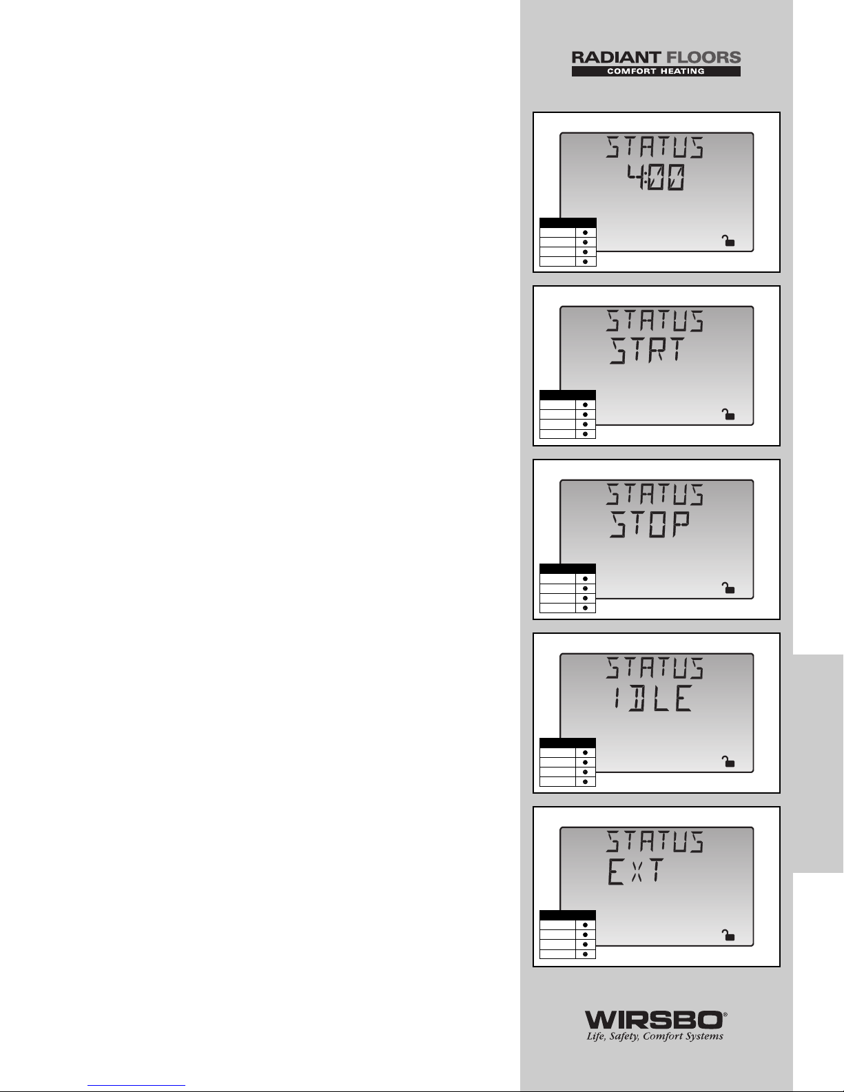
VISCOSITY COMPENSATION
(EXCEEDING ∆T MAX)
At low temperatures, glycol solutions used in snow melting
systems become very viscous and difficult to pump. In order
to overcome this condition during a cold start of a snow
melting system, the control is allowed to exceed ∆T MAX
setting for a time to warm the glycol solution.
• Allows control to compensate for the high viscosity of the
glycol solution
• Used when return temperature is below 30°F (-1°C)
NOTE: When control exceeds the ∆T MAX setting,
Maximum pointer flashes when viewing MIX ∆T
item in the View Menu.
RAMPING OF THE ∆T
When control starts applying heat to slab, supply temperature
to snow melting system is ramped up over a period of time
until it reaches maximum allowed ∆T.
OPERATING STATUS (STATUS) (See fig. b)
While in snow melting mode, an additional item is available in
the View Menu called STATUS. It displays current operating
status of snow melting system.
STRT (See fig. c)
Displayed after snow melting system has been enabled and
remains on until slab reaches melting temperature. If the slab
is at melting temperature, STRT is displayed for five seconds
after snow melting system has started operation. This is to
verify that the control has entered into snow melting mode.
STOP (See fig. d)
Displayed after the snow melt system is disabled
IDLE (See fig. e)
Displayed as long as the control is operating slab at idling
temperature
EXT (See fig. f)
Displayed when RUN TIME has reached 0:00 and control still
has an external demand for melting. In this situation, control
continues melting until snow melting demand is removed or
the control is stopped.
73
CONTROL FUNCTION
OVERVIEW
CONTROL FUNCTION OVERVIEW - Section E - Snow Melting
%
View
1
hr
b
%
View
1
c
%
View
1
d
%
View
1
e
%
View
1
f
Access Level
LTD
USER
INST
ADV
Access Level
LTD
USER
INST
ADV
Access Level
LTD
USER
INST
ADV
Access Level
LTD
USER
INST
ADV
Access Level
LTD
USER
INST
ADV
Page 76
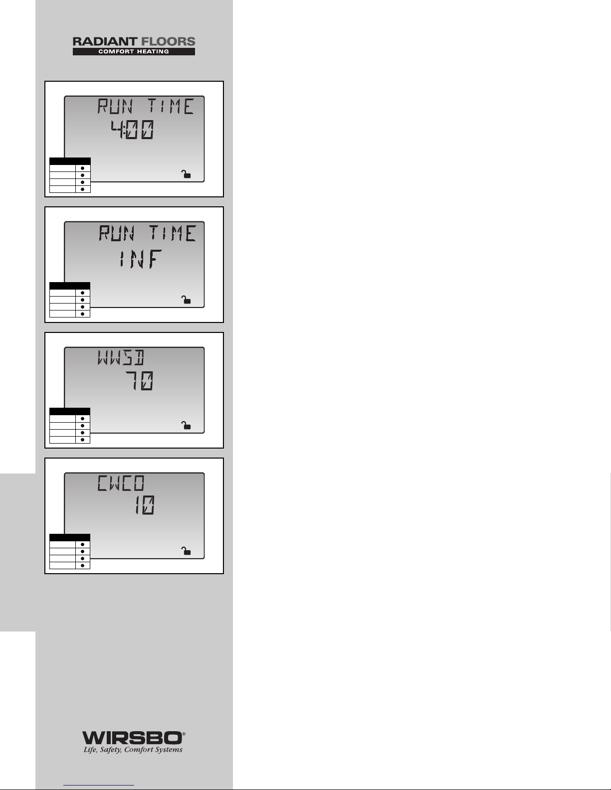
0:30 to 17:00 hr (See fig. g)
RUN TIME is displayed as long as slab is up to temperature
and the control is in the melting mode.
INF (See fig. h)
Displayed if an infinite run time is selected and the control is
in the melting mode.
WWSD (See fig. i)
Displayed when control is in a Warm Weather Shut Down
CWCO (See fig. j)
Displayed when control is in a Cold Weather Cut Out
74
CONTROL FUNCTION
OVERVIEW
CONTROL FUNCTION OVERVIEW - CONTROL FUNCTION OVERVIEW - Section E - Snow Melting
Adjust
hr
g
Adjust
h
Adjust
o
F
i
Adjust
o
F
j
Access Level
LTD
USER
INST
ADV
Access Level
LTD
USER
INST
ADV
Access Level
LTD
USER
INST
ADV
Access Level
LTD
USER
INST
ADV
Page 77

RUNNING TIME (RUN TIME) (See fig. k)
Run time is the length of time the snow melting system
operates once the slab has reached melting temperature.
• During the time slab approaches melting temperature, run
time does not decrease
• Once the slab has reached melting temperature, run time
begins counting down
• When run time reaches 0:00 (displayed by the STATUS item in
the View Menu) the control has finished the melting process
NOTE: If a slab sensor is not used, the run time
begins counting down as soon as the melting
mode is enabled.
COLD WEATHER CUT OUT (CWCO) (See fig. l)
Maintaining a slab temperature at either a melting or idling
temperature when outdoor conditions has dropped below
system design parameters can be both expensive and
impossible. Cold Weather Cut Out (CWCO) is a feature that
allows the control to automatically shut the system down at a
particular outdoor temperature setting to save energy.
• When the control is not in melting mode and the outdoor
temperature drops below the CWCO setting, the control
goes into CWCO mode which prevents any melting events to
take place until the outdoor temperature rises above the
CWCO setting.
• When the control is already in melting mode, the CWCO only
occurs when the outdoor temperature is less than CWCO
setting and slab surface is less than 29°F. This allows the
control to finish the current melting cycle and helps prevent
refreezing of left over moisture on the slab surface.
BOILER OPERATION
Refer to Section F (page 80) for a description of the boiler
operation.
BOILER PROTECTION
The SYSTEMpro 311 ensures the boiler water temperature
remains above Boil MIN setting
• If boiler water temperature begins to drop due to slab return
temperature, the mixing device is throttled back to allow the
boiler to recover
• Throttling back minimizes time boiler operates below its
condensing temperature and prolongs life expectancy of boiler
MIXING SYSTEM PUMP (P1) OPERATION
The mixing system pump (Mixing Pmp P1) contact closes and
remains closed as long as control is either in the melting or
idling mode. The mixing system pump contact shuts off if
control is in WWSD or CWCO, or if there is no call for melting
or idling.
75
CONTROL FUNCTION
OVERVIEW
CONTROL FUNCTION OVERVIEW - Section E - Snow Melting
Adjust
hr
k
Adjust
o
F
l
Access Level
LTD
USER
INST
ADV
Access Level
LTD
USER
INST
ADV
Page 78
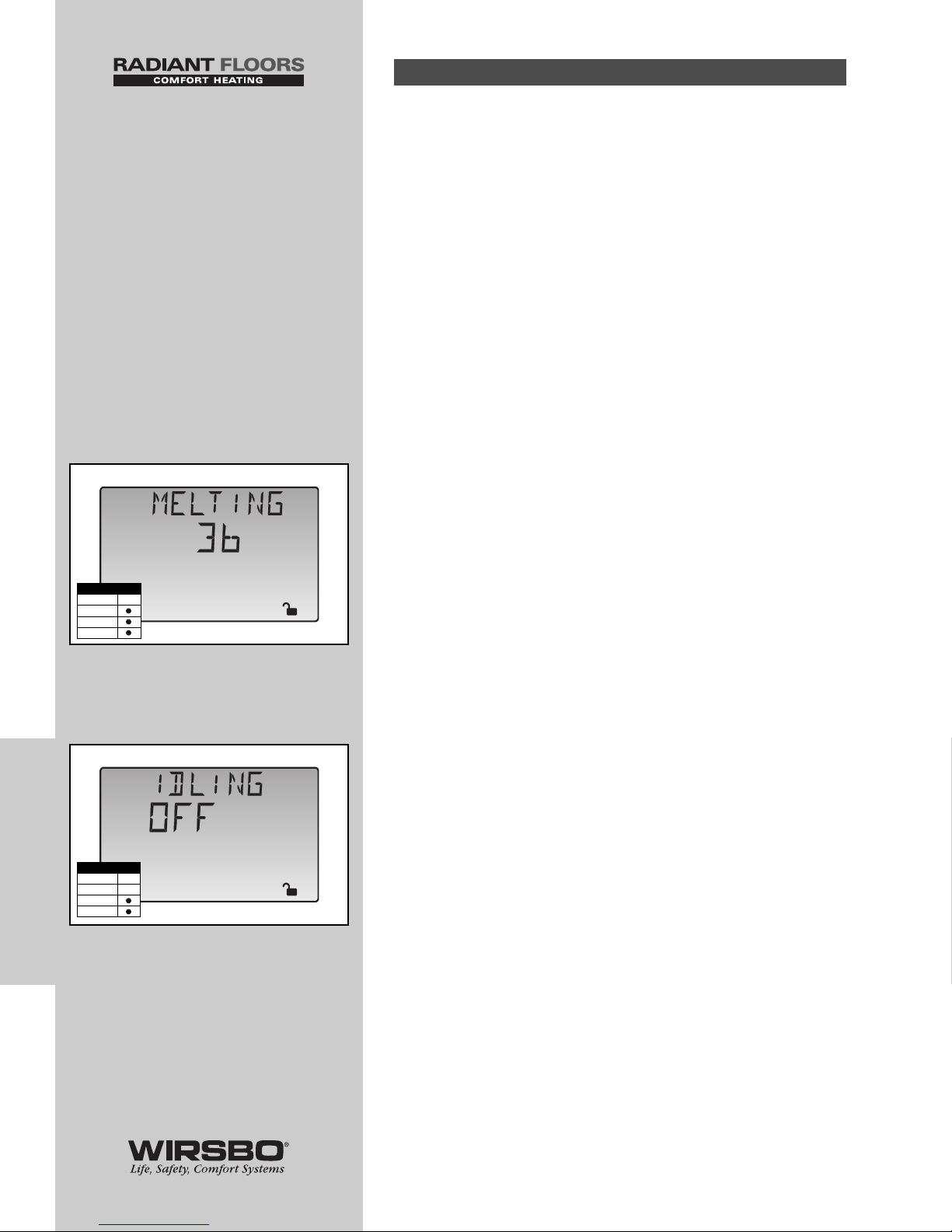
SLAB OUTDOOR RESET
When using a slab sensor, the control assumes sensor is
approximately 1 inch below surface of snow melting slab.
Since this point is closer to the source of heat, it is warmer
than the surface of the slab. So, the sensor must be
maintained at a higher temperature to ensure the surface of
slab is maintained at correct temperature.
• Amount of temperature difference between surface of slab
and slab sensor changes with outdoor air temperature
• Slab core temperature is increased as outdoor air
temperature drops
• Temperature displayed as slab temperature is the
temperature of the slab sensor
• Sensor temperature will be higher than the actual surface
temperature of the slab
MELTING MODE (MELTING) (See fig. m)
The SYSTEMpro 311 is a manual snow melting control.
• For snow melting system to start, one of four methods
described in section E4 must be used
• The MELTING setting in the Adjust Menu sets slab surface
temperature that is maintained while control is in melting
mode
NOTE: When control is in melting mode,
Melting pointer is visible in the View Menu
and either EXT, INF or a running time may be
read under STATUS item in View Menu.
IDLING MODE (IDLING) (See fig. n)
Extra time may be required when the snow melting system
starts from a cold temperature.
• To decrease melting start up time, slab can be maintained at
an “Idling” temperature
• Idle feature is also useful for preventing frost and light ice
formation
• The IDLING setting in the Adjust Menu sets slab surface
temperature that is maintained while control is in the idling
mode
NOTE: When control is in idling mode, the word IDLE
can be read under STATUS item in the View Menu.
Section E2: With Slab Sensor
76
CONTROL FUNCTION
OVERVIEW
CONTROL FUNCTION OVERVIEW - CONTROL FUNCTION OVERVIEW - Section E - Snow Melting
Adjust
o
F
m
Adjust
n
Access Level
LTD
USER
INST
ADV
Access Level
LTD
USER
INST
ADV
Page 79
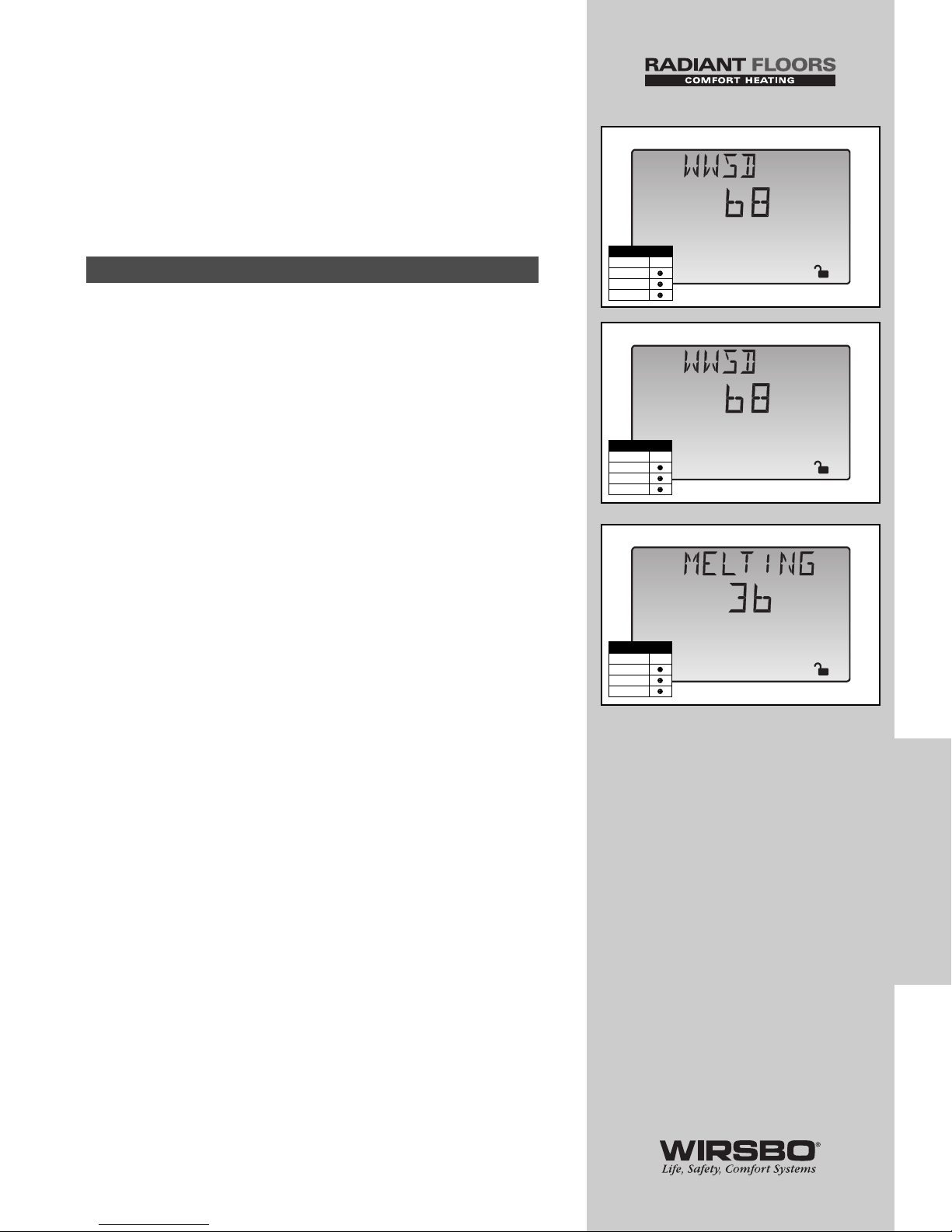
WARM WEATHER SHUT DOWN (WWSD)
(See fig. o)
The control enters into WWSD when:
• Slab and outdoor temperatures exceed MELTING
temperature by more than 1.5°F (1°C)
• In WWSD, the snow melting system is shut down to
conserve energy
In cases where a slab sensor has not been or cannot be
installed in snow melting slab, it is still possible for the
SYSTEMpro 311 to operate the snow melting system. In this
mode the control supplies a calculated mixed supply water
temperature to the slab.
NOTE: This mode of operation is generally not
recommended since the control can no longer
regulate slab temperature. As a result, it can cause
the slab to operate at surface temperatures that
are higher or lower than required. A higher surface
temperature can lead to excessive energy usage
and fuel costs. A lower surface temperature can
cause the slab to freeze over.
WARM WEATHER SHUT DOWN (WWSD)
(See fig. p)
When a slab sensor is not in use:
• The Warm Weather Shut Down is determined only from the
outdoor temperature
• If outdoor temperature rises above MELTING setting by
more than 2°F (1°C), control goes into WWSD and ignores
any demand for melting or idling
MELTING MODE (MELTING) (See fig. q)
The SYSTEMpro 311 is a manual snow melting control:
• For the snow melting system to be started, one of four
methods described in section E4 must be used
• When the control is in melting mode, the Melting pointer is
visible in View Menu
• Either EXT, INF or a running time can be read when viewing
STATUS item in View Menu
• The MELTING setting in Adjust Menu sets the theoretical
slab surface temperature that is maintained while control is
in melting mode
Section E3: Slab Without Slab Sensor
77
CONTROL FUNCTION
OVERVIEW
CONTROL FUNCTION OVERVIEW - Section E - Snow Melting
Adjust
o
F
o
Adjust
o
F
p
Access Level
LTD
USER
INST
ADV
Access Level
LTD
USER
INST
ADV
Adjust
o
F
q
Access Level
LTD
USER
INST
ADV
Page 80
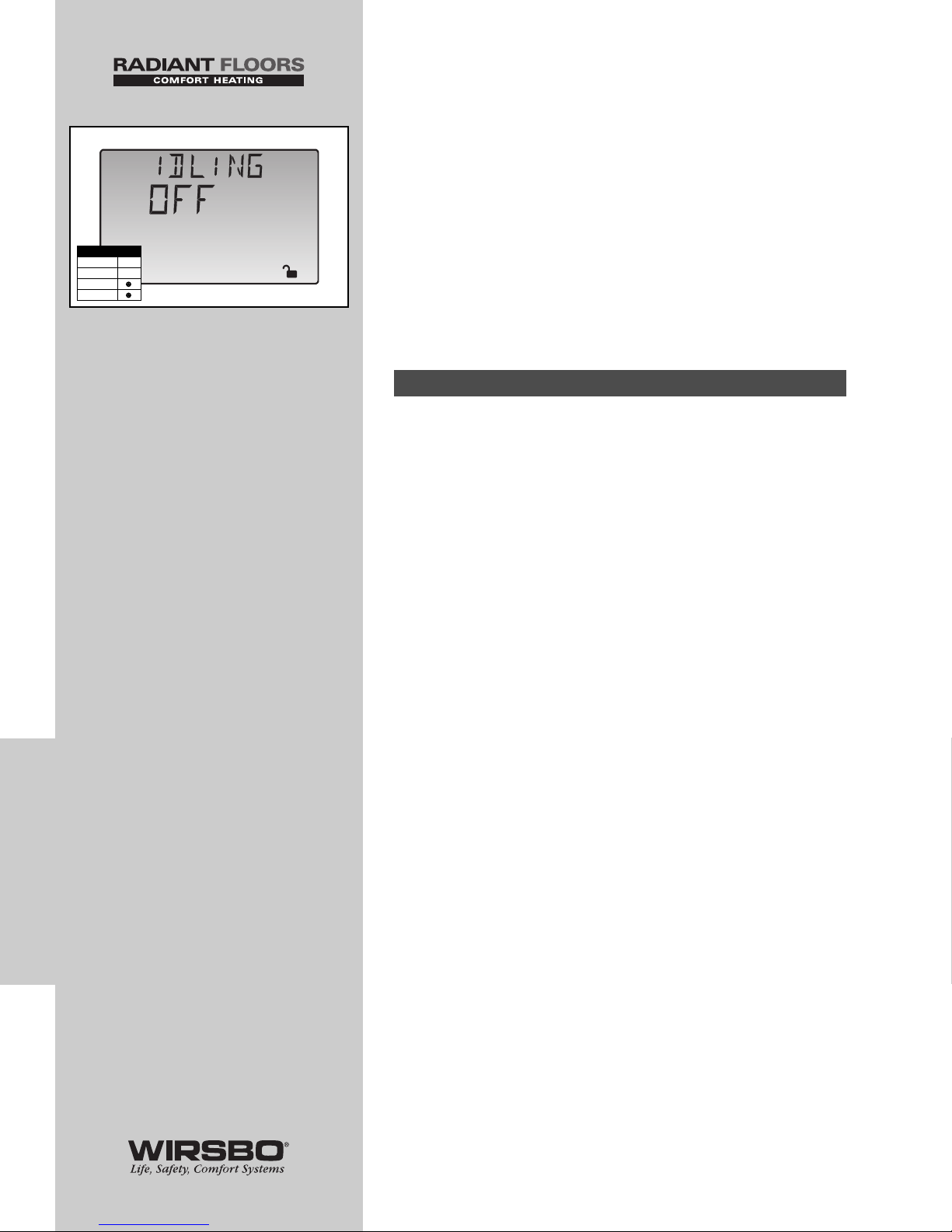
IDLING MODE (IDLING) (See fig. r)
Extra time may be required when the snow melting system
starts from a cold temperature.
• To decrease the start up time, the slab can be maintained at
an “Idling” temperature
• Idle feature is also useful for preventing frost and light ice
formation
• When control is in idling mode, the word IDLE appears in the
STATUS item in the View Menu
• IDLING setting in the Adjust Menu sets the theoretical slab
surface temperature that is kept while control is in idling
mode
There are four ways in which the snow melting system can be
enabled on the SYSTEMpro 311:
• External Mix Demand
• Snow Melt Enable Module
• Remote Display Module
• Using Start / Stop buttons on the SYSTEMpro 311
EXTERNAL MIX DEMAND
An external snow melting demand is generated when a
voltage between 24 and 240 VAC is applied across the Mix
Demand terminals (1 and 2).
• An external demand must be present for at least 4 seconds
to start snow melting system
• Once started, slab temperature is increased to MELTING
setting and maintained at MELTING temperature until RUN
TIME reaches 0:00
• If RUN TIME reaches 0:00 and external demand is still
present, control continues at MELTING temperature until
external demand is removed or system is stopped
Section E4: Snow Melt Enable
78
CONTROL FUNCTION
OVERVIEW
CONTROL FUNCTION OVERVIEW - CONTROL FUNCTION OVERVIEW - Section E - Snow Melting
Adjust
r
Access Level
LTD
USER
INST
ADV
Page 81
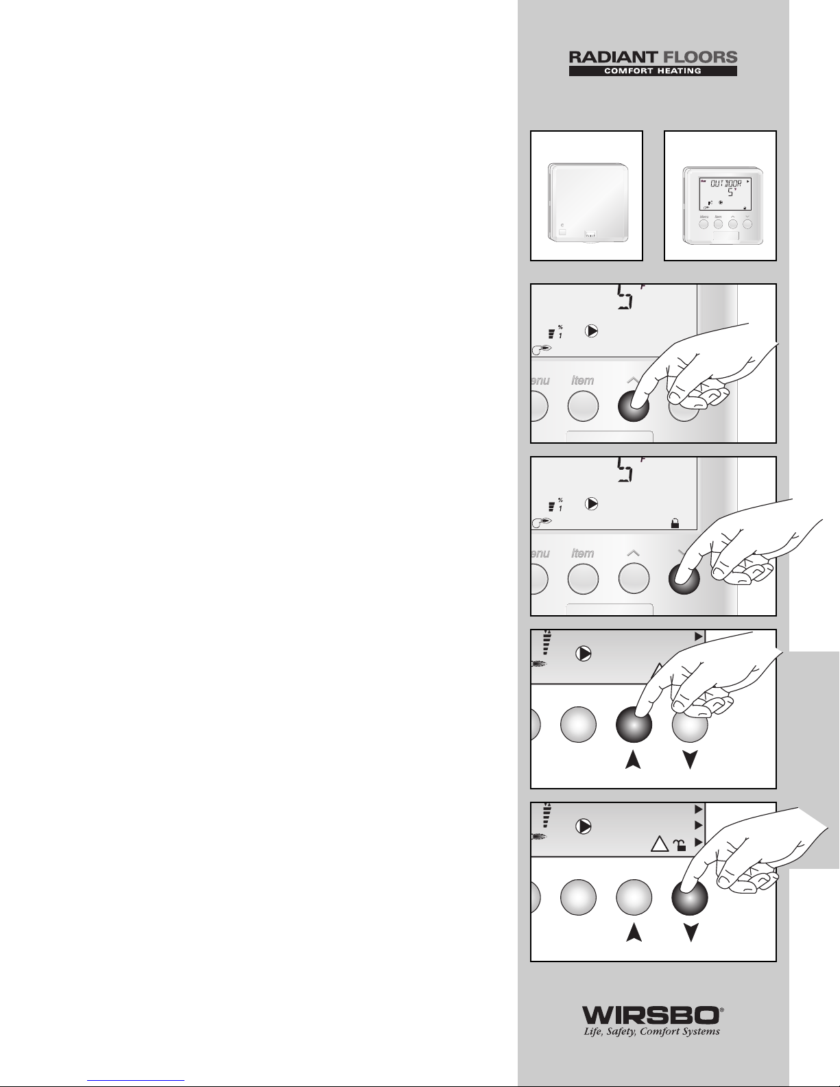
SNOW MELT ENABLE MODULE (See fig. s)
A snow melt enable module can be used to start and stop the
snow melting system. The snow melting system is enabled by
pressing the button on the front of the snow melt enable
module.
• As the slab is coming up to temperature, a green light flashes
on the front of the snow melt enable module
• Once the slab is at melting temperature and RUN TIME is
counting down, green indicator light turns solid
• To disable snow melting system when in melting mode,
press the button on the face of the snow melt enable module
• When system is stopped, a solid red indicator light is displayed
on the face of the snow melt enable module for 5 seconds
REMOTE DISPLAY MODULE (See fig. t)
A Remote Display Module can be used to start and stop snow
melting system.
• The snow melting system is enabled by pressing the
Start
(See fig. u)
button on the Remote Display Module while in
the View Menu
• Once snow melting system is enabled, the word STRT is
displayed in the LCD for at least 5 seconds
• The Remote Display Module then displays RUN TIME setting
to allow user to adjust it
• To disable snow melting system when it is in melting mode,
press the
Stop (See fig. v)
button on the Remote Display
Module
• The word STOP will be displayed
USING START / STOP BUTTONS
ON THE SYSTEMPRO 311
If there are no external demand modules connected to the
SYSTEMpro 311, the SYSTEMpro 311 will be used to operate
the snow melt system.
• The snow melting system is enabled by pressing the
Start
(See fig. w)
button on the SYSTEMpro 311 while in the View
Menu.
• Once snow melting system is enabled, the word STRT is
displayed in the LCD for at least 5 seconds
• The SYSTEMpro 311 then displays RUN TIME setting to
allow user to adjust it
• To disable snow melting system when it is in melting mode,
press the
Stop (See fig. x)
button on the SYSTEMpro 311
• The word STOP will be displayed
79
CONTROL FUNCTION OVERVIEW - Section E - Snow Melting
7
9
8
s
Minimum
Maximum
Melting
n
e
DHW
12
%
!
1
Item
Start Stop
3
Minimum
Maximum
Melting
n
e
DHW
12
%
!
1
Item
Start Stop
3
w
x
CONTROL FUNCTION
OVERVIEW
t
u
v
Page 82
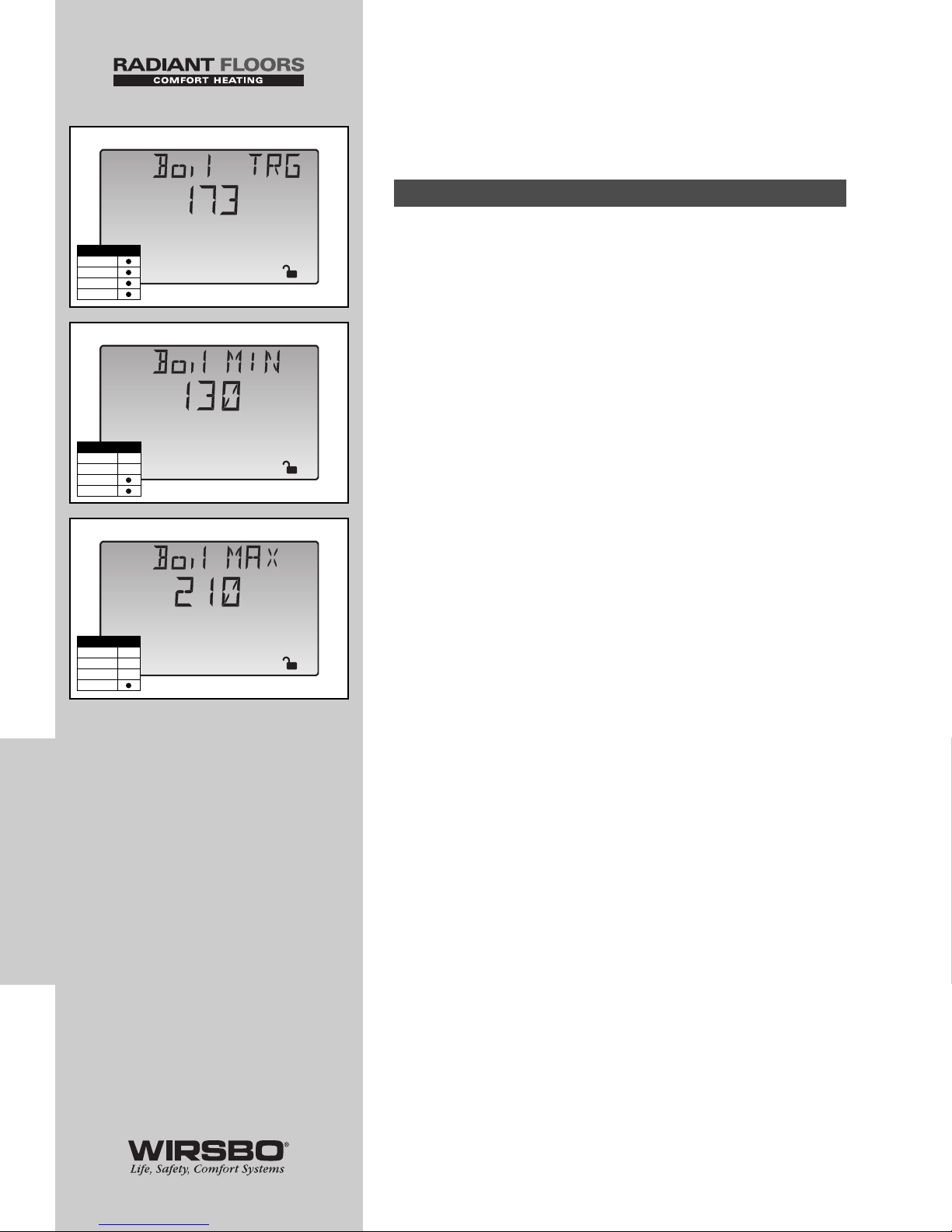
80
CONTROL FUNCTION
OVERVIEW
CONTROL FUNCTION OVERVIEW - CONTROL FUNCTION OVERVIEW - Section F - Boiler Operation
CONTROL FUNCTION
OVERVIEW - SECTION F
BOILER OPERATION
BOILER TARGET TEMPERATURE (Boil TRG)
(See fig. a)
The Boil TRG temperature is determined from the demands
that currently require heat.
• Boiler target temperature is set at least as high as the highest
temperature requirements of the current demands
• The control displays the temperature that it is currently
trying to maintain as the boiler supply temperature in Boil
TRG item in the View Menu
• If the control does not have a current requirement for heat, it
displays “---” in the LCD
BOILER MINIMUM (Boil MIN) (See fig. b)
The Boil MIN is the lowest water temperature that the
SYSTEMpro 311 is allowed to use as a Boil TRG temperature.
• During mild conditions, if the control calculates a Boil TRG
temperature below Boil MIN setting, Boil TRG temperature is
adjusted to at least the Boil MIN setting
• In this mode, if boiler is operating, and boiler supply
temperature is near Boil MIN setting, the Minimum pointer
appears in the LCD while the Boil TRG or the Boil SUP
temperature is viewed
• If installed boiler is designed for low temperature operation,
set Boil MIN adjustment to OFF
BOILER MAXIMUM (Boil MAX) (See fig. c)
The Boil MAX is the highest water temperature the control is
allowed to use as a Boil TRG temperature.
• If control calculates target Boil MAX, and Boil SUP
temperature is near Boil MAX temperature, the Maximum
pointer turns on in the LCD while the Boil TRG or the Boil
SUP temperature is viewed
• At no time does the control operate the boiler above 248°F
(120°C).
Section F1: Boiler Supply Sensor
Adjust
o
F
b
Adjust
o
F
c
Access Level
LTD
USER
INST
ADV
Access Level
LTD
USER
INST
ADV
%
View
o
F
1
a
Access Level
LTD
USER
INST
ADV
Page 83
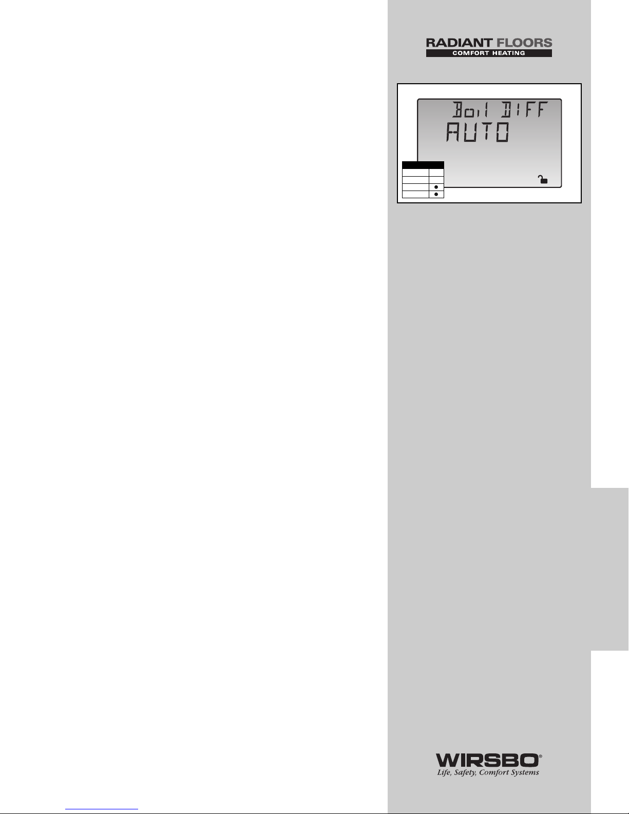
DIFFERENTIAL (Boil DIFF) (See fig. d)
An on/off heat source such as a boiler must be operated with
a differential to prevent short cycling. This differential is
centered around the Boil TRG temperature
• If boiler supply temperature drops 1/2 of the differential
setting below Boil TRG temperature, the control closes Boiler
contact to fire boiler
• If boiler supply temperature rises 1/2 of the differential
setting above the Boil TRG temperature, the control opens
Boiler contact to turn off boiler
• The SYSTEMpro 311 offers either a fixed or automatic
differential setting
• If AUTO differential is selected, the control automatically
adjusts boiler differential setting under current load
conditions to minimize short cycling
BOILER OPERATION
When the SYSTEMpro 311 notices that boiler operation is
required, Boiler contact terminals (15 and 16) close. While the
Boiler contact is closed, the burner segment in the LCD is
displayed.
BOILER PURGE
After all demands are satisfied, the SYSTEMpro 311 continues
to operate primary pump (P3, terminal 8) for 20 seconds.
• Allows any excess heat to be purged out of boiler after
burner is shut off
• Helps prevent water in the boiler from flashing into steam
after boiler is shut off
• There must not be any motorized valves to restrict water
flow through pump and boiler
81
CONTROL FUNCTION
OVERVIEW
CONTROL FUNCTION OVERVIEW - Section F - Boiler Operation
Adjust
d
Access Level
LTD
USER
INST
ADV
Page 84

CONTROL FUNCTION
OVERVIEW - SECTION G
TROUBLESHOOTING
When troubleshooting any heating system, it is a good idea to
establish a set routine to follow. Below is an example of a
sequence you can use when diagnosing or troubleshooting
problems in a hydronic heating system.
Establish the problem
Get as much information from the customer as possible about
the problem:
• Is there too much heat, not enough heat or no heat?
• Is the problem only in one zone or does the problem affect
the entire system?
• Is this a consistent problem or only intermittent?
• For how long has the problem existed?
This information is critical in correctly diagnosing the
problem.
Understand the sequence
of operation of the system
If a particular zone is not receiving enough heat, check:
• Which pumps or valves in the system must operate to
deliver heat to the affected zone?
If the zone is receiving too much heat, check:
• Which pumps, valves or check valves must operate to stop
delivery of heat?
NOW, Press the Test button on the control and follow it
through the test sequence as described in the Testing section.
Pause the control as necessary to make sure the correct device
is operating as it should
82
CONTROL FUNCTION
OVERVIEW
CONTROL FUNCTION OVERVIEW - CONTROL FUNCTION OVERVIEW - Section G - Troubleshooting
Page 85

83
CONTROL FUNCTION
OVERVIEW
CONTROL FUNCTION OVERVIEW - Section G - Troubleshooting
Sketch the piping of the system
Making a sketch of the system piping before installation is a
simple step that is often overlooked. This sketch can save
hours of troubleshooting by identifying some of the following:
• Flow directions in the system, the location of the pumps,
check valves, pressure bypass valves and mixing valves
• The correct flow direction of all pumps
This is also a very useful step if additional assistance is
required.
Document the control for future reference
Before making any adjustments to the control, write down all
of the items that the control is currently displaying. Include
items such as:
• Error messages
• Current temperatures
• Settings
• Which devices should be operating as indicated by the LCD
This information is an essential step if additional assistance is
required to diagnose the problem.
Isolate the problem between the
control and the system
Now that the sequence of operation is known and the system
is sketched:
• Is the control operating proper pumps and valves at the
correct times?
• Is the control receiving correct signals from the system about
when it should be operating?
• Are proper items selected in menus of the control for the
device that is to be operated?
Test the contacts, voltages and sensors
Using a multimeter:
• Ensure that the control is receiving adequate voltage to the
power terminals and the demand terminals as noted in the
technical data
• Determine if the internal contacts on the control are opening
and closing correctly
• Follow the instructions in the Testing the Wiring section to
simulate the closed contacts on the terminal blocks as
required
• Test the sensors and their wiring as described in earlier
section
Page 86

APPENDIX
TABLE OF CONTENTS
IVariable Speed Injection Mixing.............................. 85-87
II SYSTEMpro 311 Menu Tree .................................... 88-89
III Application Drawings ................................................ 90-97
IV Error Message Overview ........................................ 98-101
V SYSTEMpro 311 Program Setup ........................ 102-103
NOTES:
84
APPENDIX
APPENDIX - APPENDIX - Table of Contents
Page 87
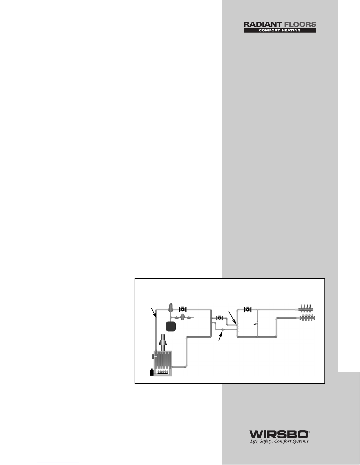
85
APPENDIX I
APPENDIX I - Variable Speed Injection Mixing
Variable Speed Injection Mixing
For Hydronic Heating Systems
The purpose of this section is to discuss the use of variable
speed injection mixing to precisely transfer heat from the high
temperature boiler (primary) loop to the lower temperature
radiant (secondary) loop in hydronic heating systems.
Various devices and plumbing arrangements can be used to
accomplish this transfer. In the past, it was common to use a
mixing valve in order to temper the water between the
primary and secondary loops in a system. In some instances,
the heat source (condensing or electric boiler, geo-thermal
heat pump, etc.) can be operated at lower temperatures and
dedicated solely to operating a low temperature radiant
heating system. In the vast majority of systems, mixing is
required because:
• A boiler minimum operating temperature is required
• High temperature water is required for other system needs
• Water temperatures vary over a wide range (e.g. solar heat
sources, waste heat utilization, wood fired boilers, etc.)
When the available heat source produces higher water
temperatures than is required by the radiant heating system,
a tempering device is required. To achieve the lower water
temperature required for the radiant system, the high
temperature boiler water must be blended or injected into the
return side of the radiant system to a level that meets the
required supply water temperature for the radiant side.
Technologies have evolved to the point of using small "wet
rotor" pumps to accurately adjust the secondary radiant
supply water temperature regardless of the flow activities on
either primary or secondary loops.
(See fig. a)
The speed of the injection pump
is automatically adjusted to
deliver the desired volume of
hot boiler water to the lower
temperature radiant loop. The
injection pump speed is
constantly adjusted as the
radiant heating system demand
and the supply water
temperature change. If the
boiler return temperature
becomes too cold, the injection
pump can be slowed down to
reduce the heat injection rate,
resulting in an increased boiler
return temperature.
Wirsbo offers a variety of controls that utilizes variable speed
injection pump output. This output modulates the power
supply to the circulator to vary its rotational speed. For
residential and many commercial systems, the controls have
a 120 VAC 50/60Hz output to directly power small circulators.
Radiant
System
a Mixing with variable speed pump
System
Pump
High
Te mperature
(Primary)
Loop
Valve
Injection
Point
Primary
Pump
Boiler
Page 88
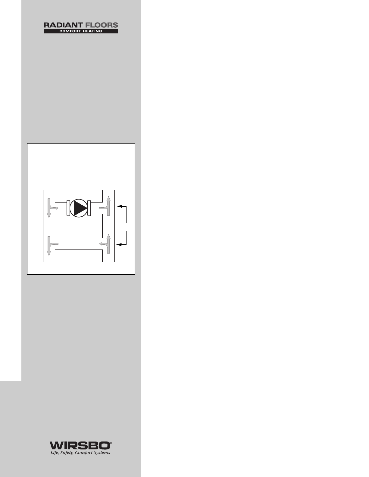
86
A permanent capacitor, impedance protected motor (no start
switch) on the circulator is required. The maximum allowable
amperage for this output is 2.2 amps, which limits the
allowable circulator size to 1/6 HP.
This type of system can use a small circulator to inject a high
BTU input into a relatively large system flow. Typically, the
injection pump need only deliver 1/6 to 1/4 of the system flow
for low temperature radiant panels if high temperature water
is available for injection. In small hydronic systems, the
smallest available circulator for variable speed injection may
be too large. It is important to properly size the injection pump
and use a globe valve on the return injection leg.
For proper injection pump sizing, the designer must know the
following information:
(See fig. b)
F
V
= Flow Rate (Injection Loop) in GPM
F
1
= Radiant (Secondary Loop) Flow Rate in GPM
T
1
= Boiler (Primary Loop) Supply Temperature
T
2
= Radiant (Secondary Loop) Supply Temperature
T
R
= Radiant (Secondary Loop) Return Temperature
T
D
= Radiant (Secondary Loop) Temperature
Differential (
T
2
- TR)
Note: All values are to be given at design
conditions. The formula used for sizing the
injection pump is shown below.
F
V
= (F1x TD) / (T1- TR)
Example:
If values at design conditions are:
F
1
= Radiant (Secondary) Flow = 30 GPM
T
1
= Boiler (Primary) Supply = 180°F
T
2
= Radiant (Secondary) Supply = 140°F
T
R
= Radiant (Secondary) Return = 120°F
T
D
= Radiant (Secondary) Differential = 20°F
To find the injection pump flow rate:
F
V
= (30 x 20) / (180 - 120)
F
V
= (600) / (60)
F
V
= 10 GPM
APPENDIX I
APPENDIX I - Variable Speed Injection Mixing
b Direct Injection Mixing
“FV” to be calculated
Variable
Speed
Injection
Pump
Supply To LOW
Temperature Loop
T
2F1
Supply From HIGH
Temperature Loop
T
1
TRF
1
“DIRECT” INJECTION
F
V
F
V
T
D
Direct Injection
F
V
= (F1x TD) / (T1- TR)
Page 89
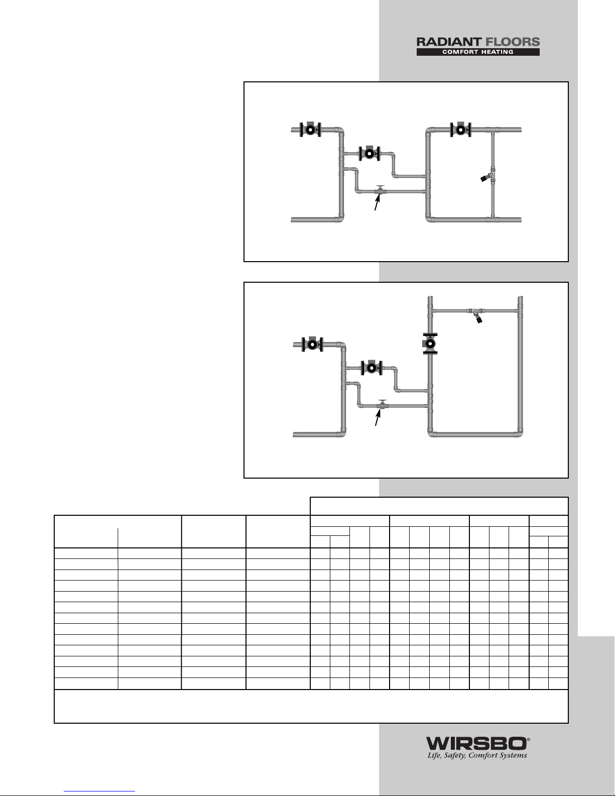
87
In order to provide the proper amount and temperature of
supply water on the radiant heating loop, the variable speed
injection pump needs only to inject 10 GPM at design
conditions.
Figures c and d
show the two
most common piping layouts for
variable speed injection mixing.
Pay particular attention to the drop
lines (or thermal traps) shown
in the injection legs. These are
particularly important to prevent
"thermal siphoning" from the
primary loop into the secondary
loop. Consult the pump
manufacturers' chart (below) to
assist in the selection of the proper
injection pump for the project.
In the piping arrangement shown,
the variable speed injection pumps
are plumbed in such a way as to
limit head pressure in the injection
legs to only a few feet at most.
Use standard pressure drop
calculations and equivalent length
of feet charts for exact calculations
if required.
APPENDIX I
APPENDIX I - Variable Speed Injection Mixing
To LOW
Te mperature
Heating System
c Injection into a horizontal loop
System
Pump
Balancing
Valve
Variable
Speed
Injection
Pump
Primary
Pump
From HIGH
Temperature
Loop
}
}
}
Note #2
Note #1
Note #3
}
Note #2
}
}
Note #2
Note #1
}
Note #2
To LOW
Te mperature
Heating System
d Injection into a vertical loop
System
Pump
Balancing
Valve
Variable
Speed
Injection
Pump
Primary
Pump
From HIGH
Temperature
Loop
}
}
Note #1
Note #3
}
Note #2
}
}
Note #2
Note #1
}
Note #2
Note #1 - Maximum 4 Pipe Diameters Apart
Note #2 - Minimum 6 Pipe Diameters Apart
Note #3 - Drop line to be longer than 1 foot
Note #1 - Maximum 4 Pipe Diameters Apart
Note #2 - Minimum 6 Pipe Diameters Apart
Note #3 - Drop line to be longer than 1 foot
– 1.5 - 2.0 20 0.5 X X X X X
2.5 2 100 0.5 X
4 - 5.5 3.0 - 4.5 100 0.5 X X X X X X
4.5 - 6.5 4 - 5.5 100 0.75 X X
9 - 10.5 7.5 - 8.5 100 0.75 X X X X
98100 1 X
14 - 15 12 - 13 100 1 X X X
19 17 100 1.25 X
22 - 24 19 - 21 100 1.25 X X X
26 - 28 – 100 1.5 X X X
35 - 37 31 - 32 100 1.5 X X
33 30 100 2 X
41 - 45 39 - 42 100 2 X X
Design Injection Flow Rate (US GPM) Turns open of Nominal Pipe Grundfos (F) Taco B&G Armstrong
Without With the Globe Valve Diameter 15-42 Astro
Globe Valve Globe Valve (%) (inches)
2* 3**
26-64
003
007
0010
0012
NRF9NRF22NRF
33 30 50
43-75
* Speed 2, ** Speed 3 (Brute)
Table courtesy of tekmar - This table assumes there are 5 feet of pipe, 4 elbows, and branch trees of the listed diameter.
These circulators have been tested and approved by the manufacturers for use with the tekmar variable speed electronics.
Manufacturer Approved Pump Models
Variable Speed Injection Design Flow Rates
Page 90
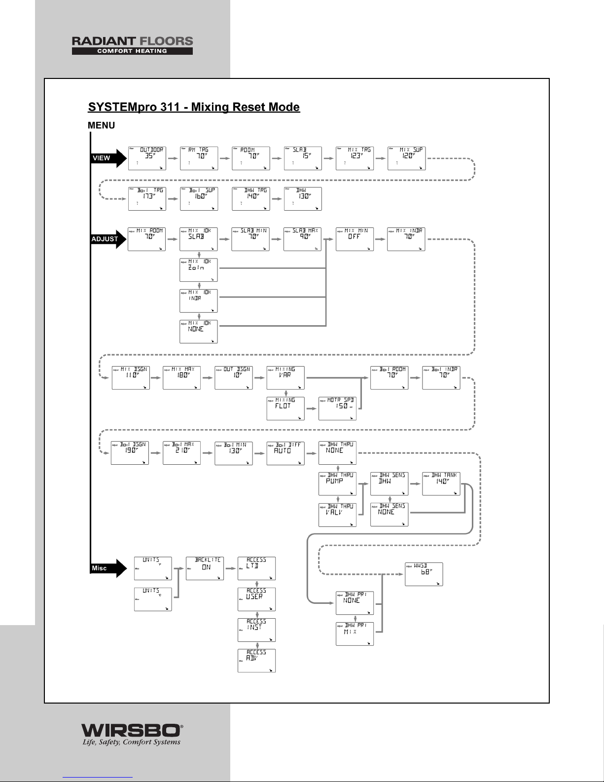
88
APPENDIX II
APPENDIX II - SYSTEMpro 311 Menu Tree
Page 91
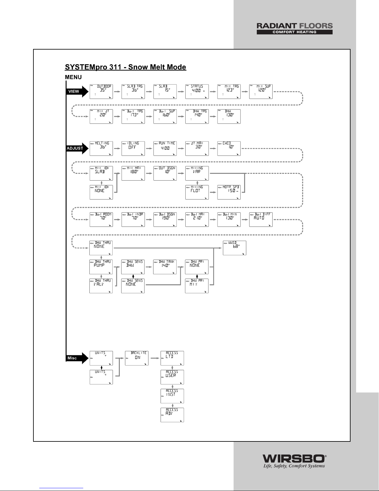
89
APPENDIX II
APPENDIX II - SYSTEMpro 311 Menu Tree
Page 92
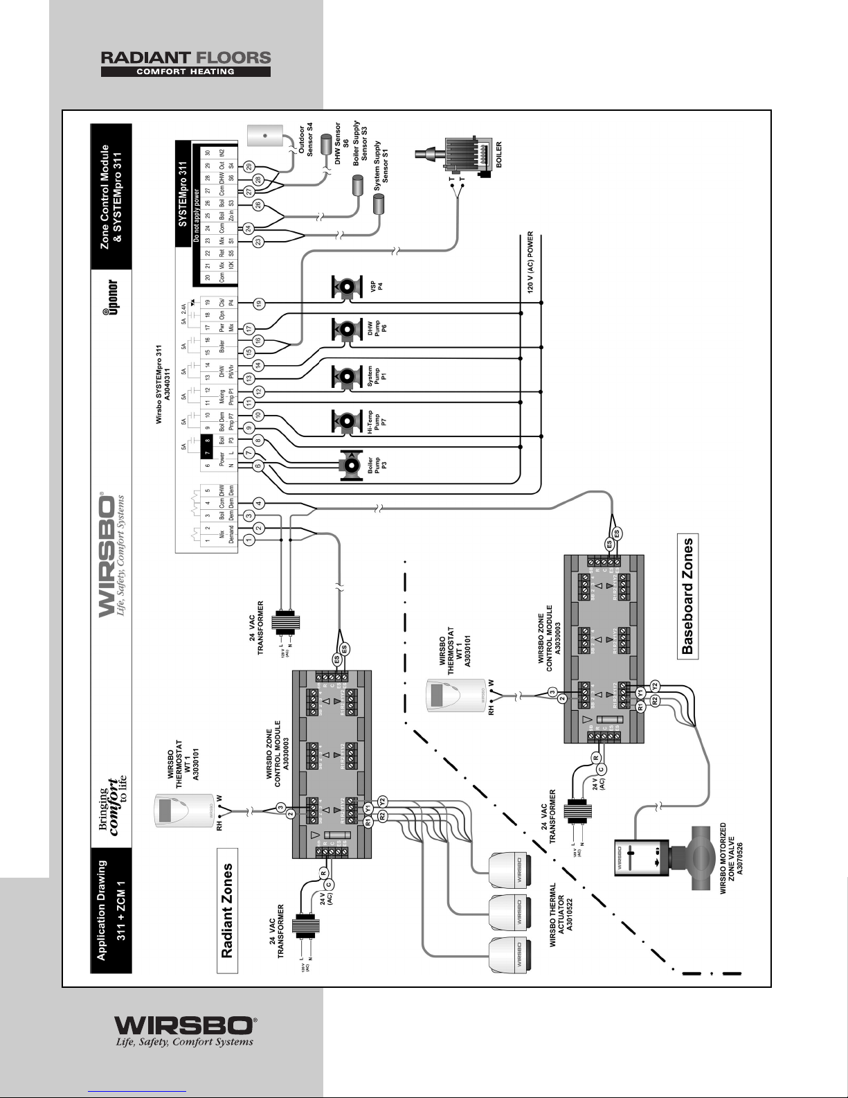
90
APPENDIX III
APPENDIX III - Application Drawings
Page 93
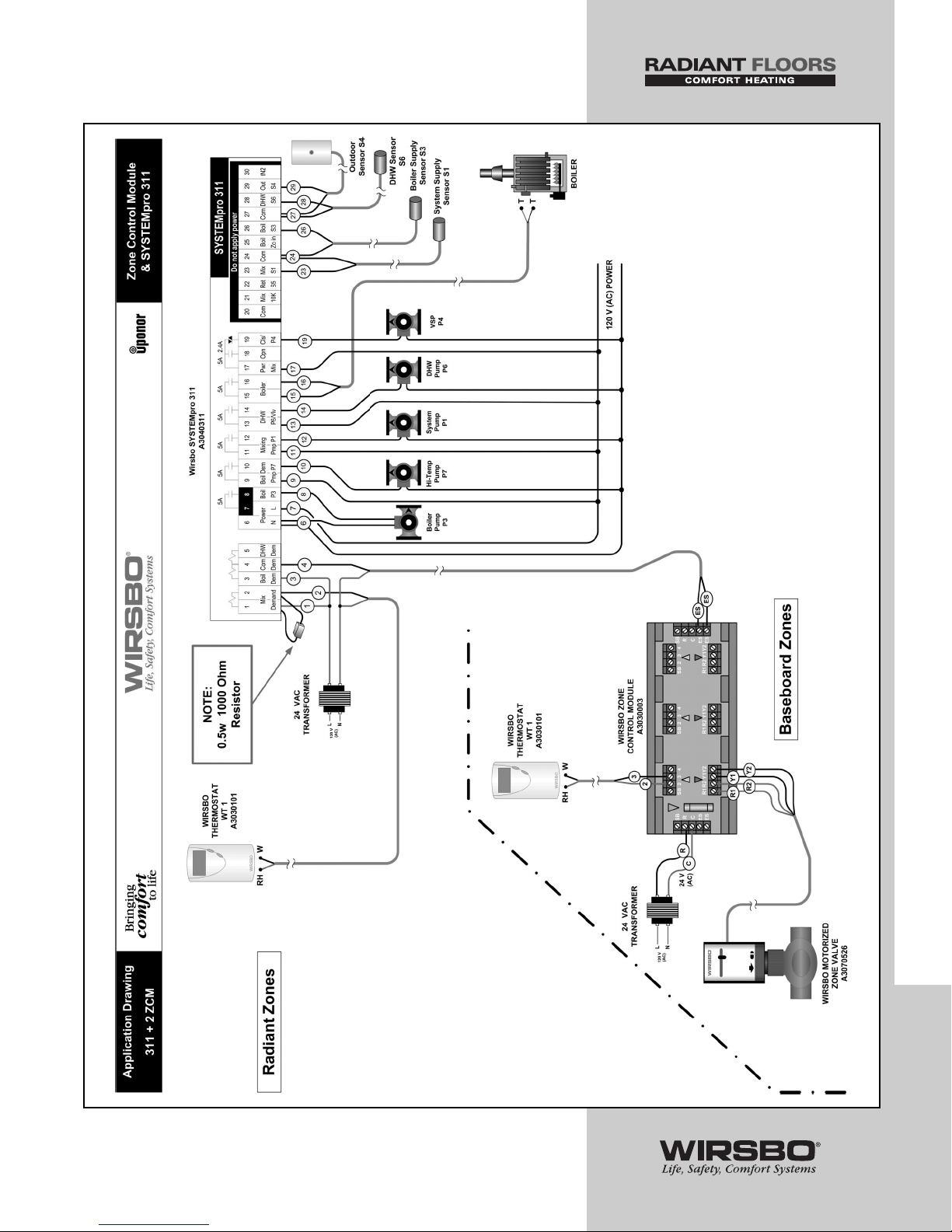
91
APPENDIX III
APPENDIX III - Application Drawings
Page 94
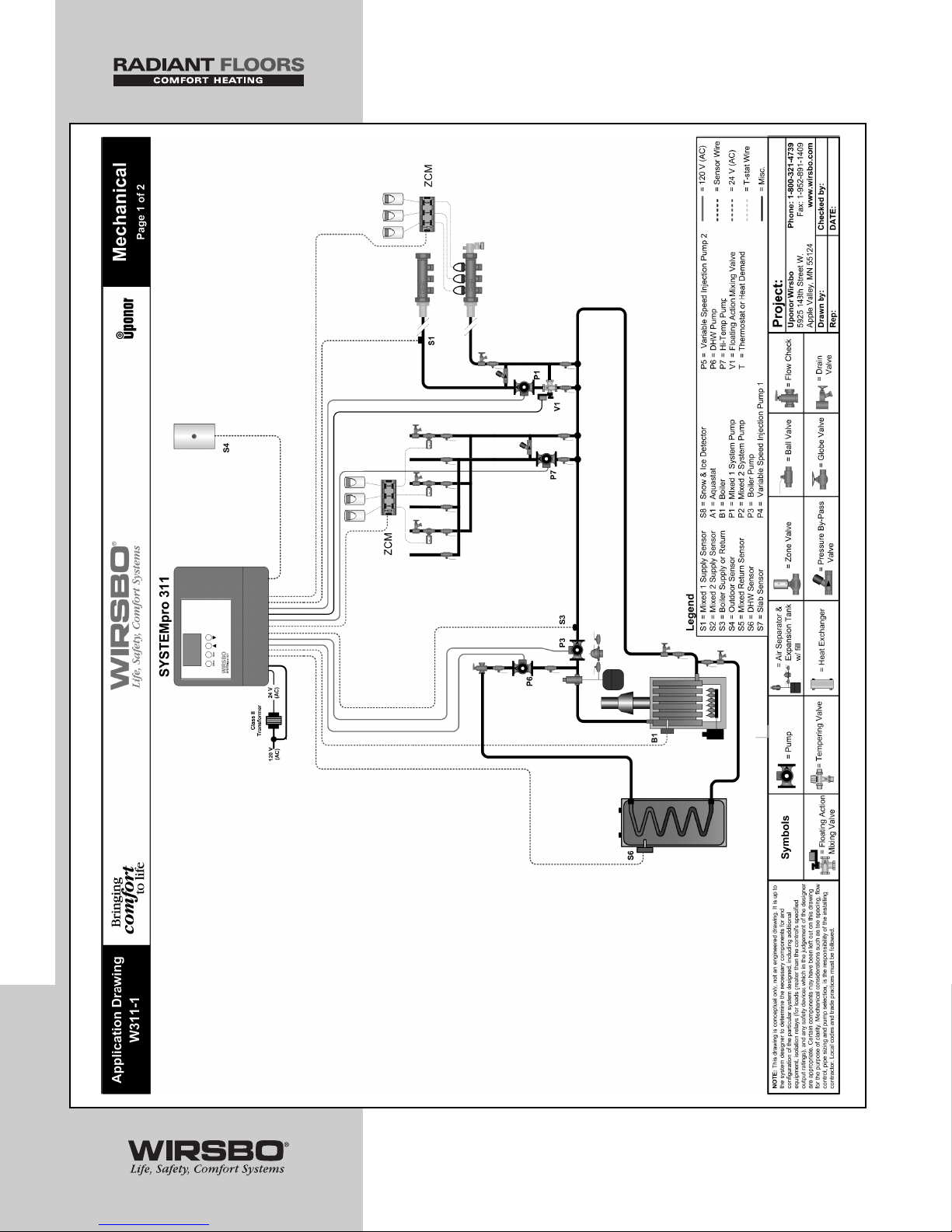
92
APPENDIX III
APPENDIX III - Application Drawings
Page 95
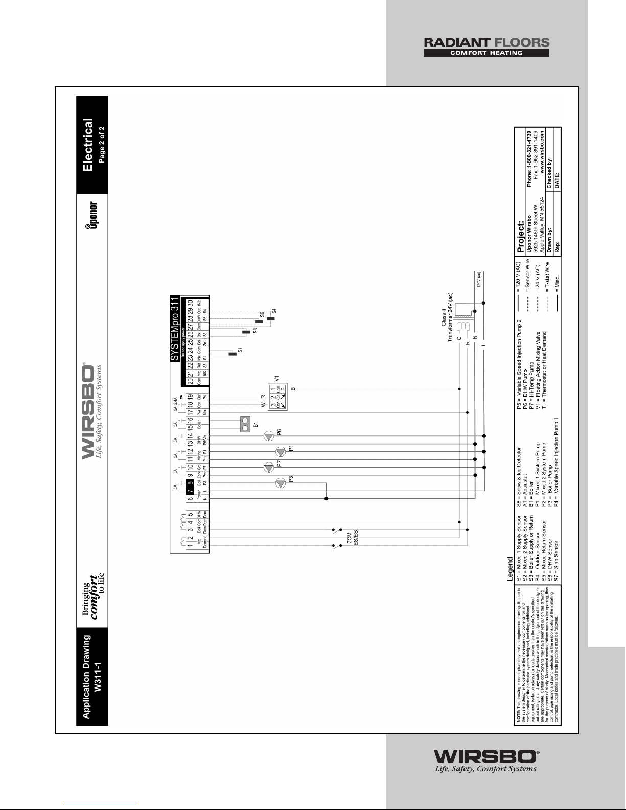
93
APPENDIX III
APPENDIX III - Application Drawings
Page 96
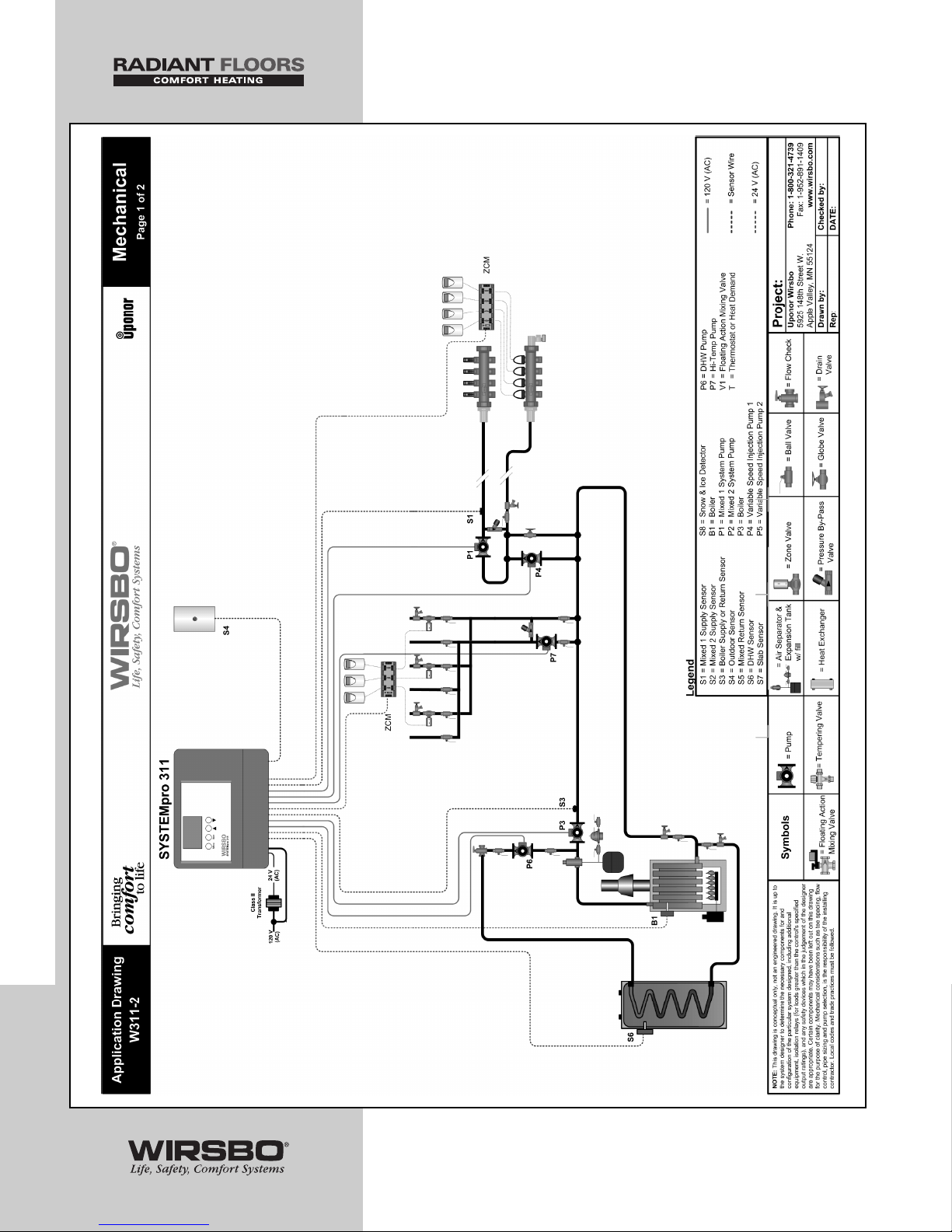
94
APPENDIX III
APPENDIX III - Application Drawings
Page 97
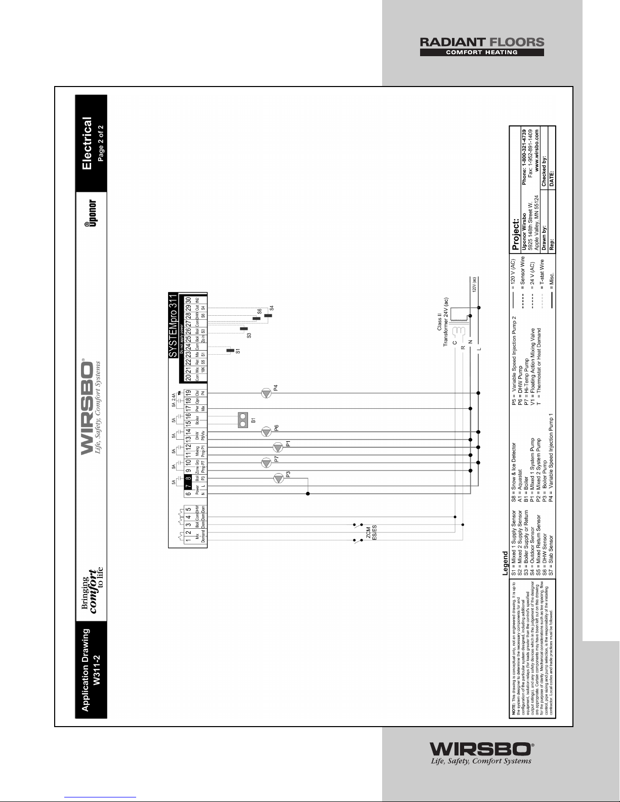
95
APPENDIX III
APPENDIX III - Application Drawings
Page 98
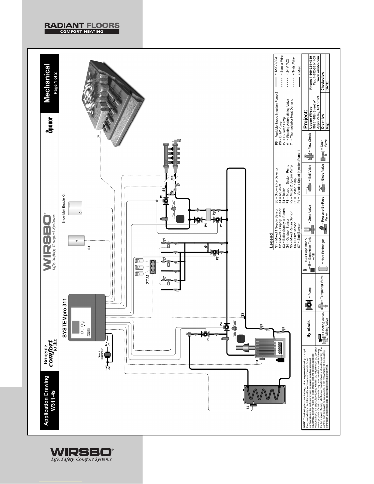
96
APPENDIX III
APPENDIX III - Application Drawings
Page 99
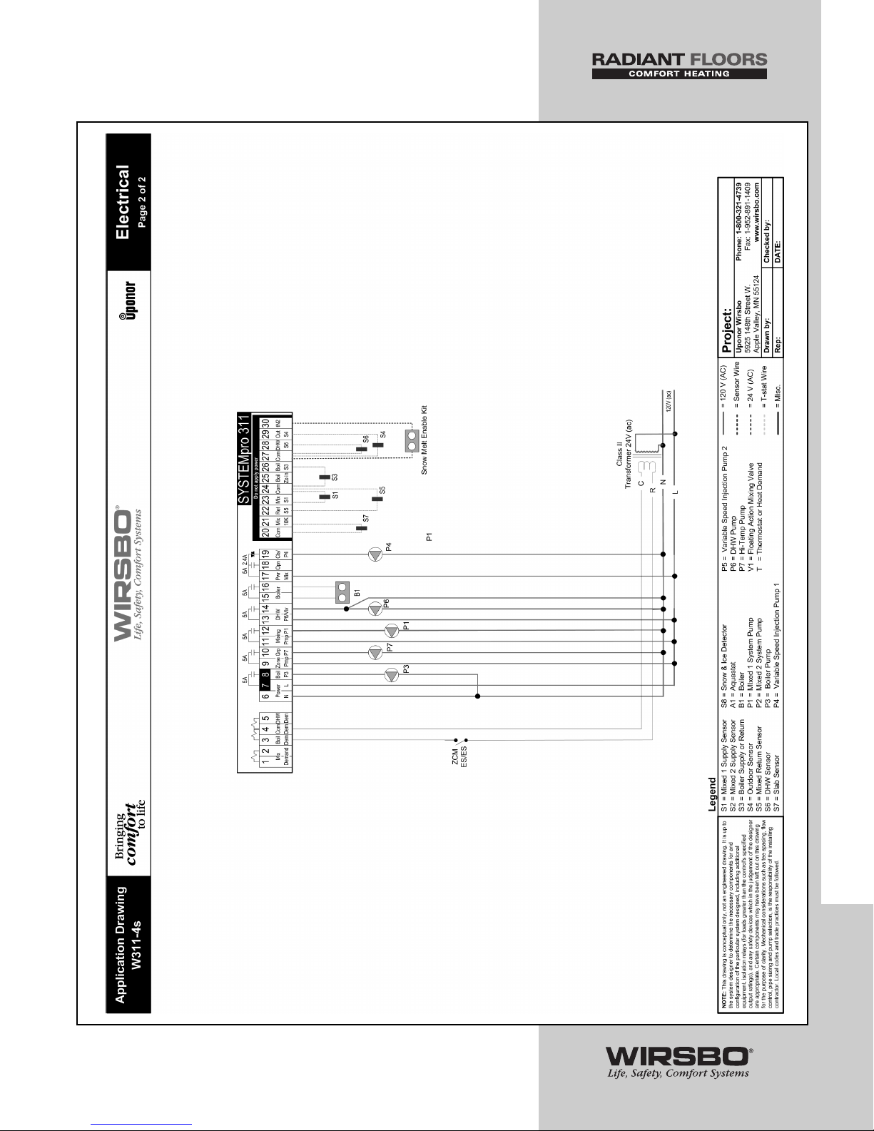
97
APPENDIX III
APPENDIX III - Application Drawings
Page 100
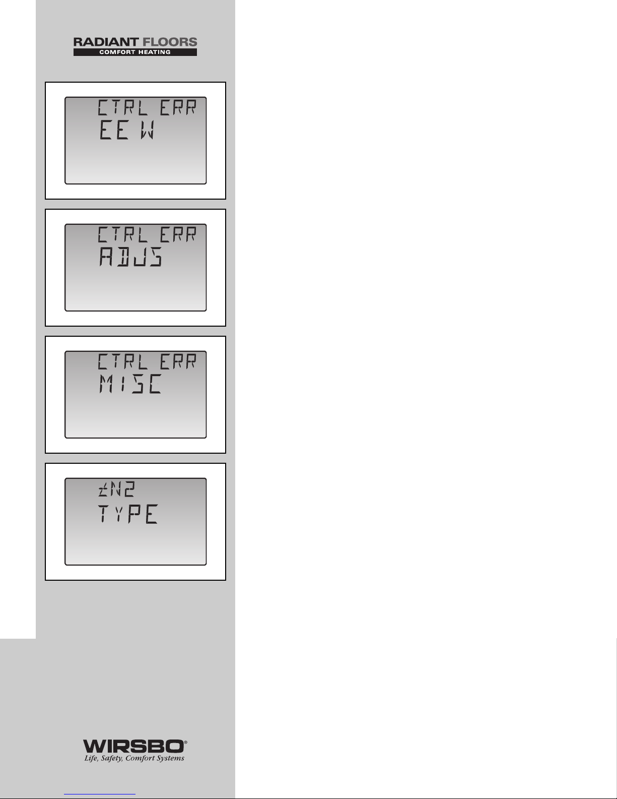
Error Messages
The control was unable to store a piece of information into its
EEPROM. This error can be caused by a noisy power source.
The control will display the error message and will continue to
operate as normal. Pressing either the Menu or Item button will clear
this error.
(See fig. a)
The control was unable to read a piece of information stored in the
Adjust Menu. Because of this, the control was required to load the
factory settings into all of the items in the Adjust Menu. The control
will stop operation until all of the items available in the Adjust Menu
of the control have been checked by the user or installer.
(See fig. b)
NOTE: Access level must be set
to ADV in order to clear the error.
The control was unable to read a piece of information stored in the
Miscellaneous Menu. Because of this, the control was required to
load factory settings into all of the items in the Miscellaneous Menu.
The control will continue to display the error message until all of the
items available in the Misc Menu of the control have been checked
by the user or installer.
(See fig. c)
NOTE: Access level must be set
to ADV in order to clear the error.
An incorrect device has been connected to the (tN2) input terminal.
To correct this error, ensure that the correct device is being used.
Once the problem has been corrected, press either the Menu or Item
button to clear the error message from the control.
(See fig. d)
98
APPENDIX IV
APPENDIX IV - Error Message Overview
a
b
c
d
 Loading...