

Page 1
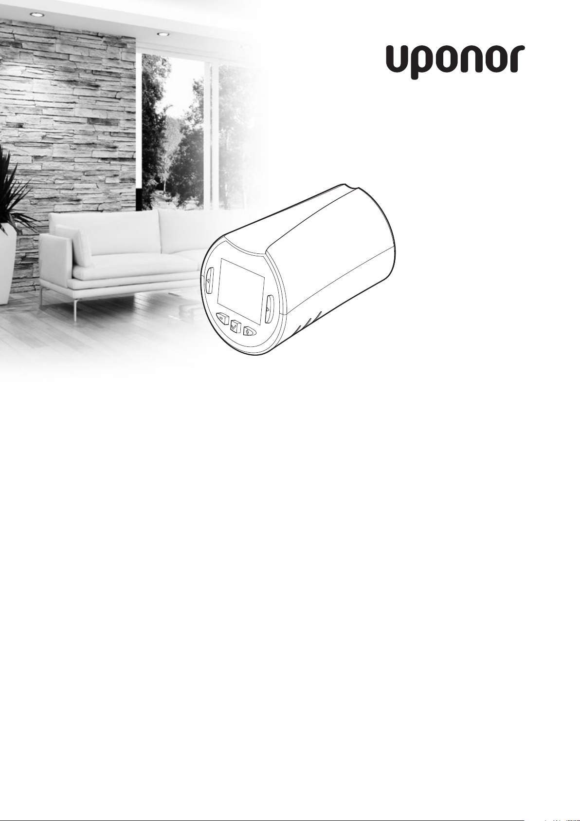
Uponor Smatrix
Wave Thermostatic
Head
EN QUICK GUIDE
07 | 2016
Page 2

EN
CZ
DE
QUICK GUIDE
Contents
Copyright and disclaimer ..............................................3
DK
EE
ES
FI
FR
HR
HU
IT
LT
Preface ..........................................................................4
Safety instructions ............................................................4
Limitations for radio transmission......................................4
Correct disposal of this product (Waste Electrical and
Electronic Equipment) .......................................................4
Quick Guide ...................................................................5
Thermostatic head operating instruction ...........................5
Installation ........................................................................5
Unregister a thermostatic head .........................................8
Technical data ...............................................................8
LV
NL
NO
PL
PT
RO
RU
SE
SI
Uponor Smatrix
Uponor Smatrix
Wave/Wave PLUS
Uponor Smatrix
Wave/Wave PLUS
UK INSTALLATION AND OPERATION
MANUAL
Wave/Wave PLUS
UK INSTALLATION AND OPERATION
MANUAL
UK INSTALLATION AND OPERATION
MANUAL
03 | 2015
03 | 2015
03 | 2015
https://www.uponor.com/smatrix/downloads.aspx
SK
2
UPONOR SMATRIX WAVE THERMOSTATIC HEAD · QUICK GUIDE
Page 3

QUICK GUIDE
Copyright and disclaimer
EN
CZ
DE
Uponor has prepared this installation and operation
manual and all the content included solely for
information purposes. The contents of the manual
(including graphics, logos, icons, text, and images)
are copyrighted and protected by worldwide copyright
laws and treaty provisions. You agree to comply with
all copyright laws worldwide in your use of the manual.
Modification or use of any of the contents of the
manual for any other purpose is a violation of Uponor’s
copyright, trademark and other proprietary rights.
The presumption for the manual is that the safety
measures have been fully complied with and, further,
that Uponor Smatrix Wave/Wave PLUS, including any
components that are part of such system, covered by
the manual:
• is selected, planned and installed and put into
operation by a licensed and competent planner and
installer in compliance with current (at the time
of installation) installation instructions provided
by Uponor as well as in compliance with all
applicable building and plumbing codes and other
requirements and guidelines;
• has not been (temporarily or continuously) exposed
to temperatures, pressure and/or voltages that
exceed the limits printed on the products or stated
in any instructions supplied by Uponor;
• remain in its originally installed location and is not
repaired, replaced or interfered with, without prior
written consent of Uponor;
• is connected to potable water supplies or
compatible plumbing, heating and/or cooling
products approved or specified by Uponor;
While Uponor has made efforts to ensure that the
manual is accurate, Uponor does not guarantee or
warrant the accuracy of the information contained
herein. Uponor reserves the right to modify the
specifications and features described herein, or
discontinue manufacture of Uponor Smatrix Wave/
Wave PLUS described at any time without prior notice
or obligation. The manual is provided “as is” without
warranties of any kind, either expressed or implied. The
information should be independently verified before
using it in any manner.
To the fullest extent permissible, Uponor disclaims
all warranties, expressed or implied, including,
but not limited to, the implied warranties of
merchantability, fitness for particular purpose and
non-infringement.
This disclaimer applies to, but is not limited to, the
accuracy, reliability or correctness of the manual.
Under no circumstances shall Uponor be liable for
any indirect, special, incidental or consequential
damages or loss that result from the use of or
the inability to use the materials or information
in the manual, or any claim attributable to errors,
omission or other inaccuracies in the manual, even
if Uponor has been advised of the possibility of
such damages.
This disclaimer and any provisions in the manual
do not limit any statutory rights of consumers.
DK
EE
ES
FI
FR
HR
HU
IT
LT
LV
NL
NO
• is not connected to or used with non-Uponor
products, parts or components except for those
approved or specified by Uponor; and
• does not show evidence of tampering, mishandling,
insufficient maintenance, improper storage, neglect
or accidental damage before installation and being
put into operation.
UPONOR SMATRIX WAVE THERMOSTATIC HEAD · QUICK GUIDE
PL
PT
RO
RU
SE
SI
SK
3
Page 4
EN
CZ
DE
QUICK GUIDE
Preface
DK
EE
ES
FI
FR
HR
HU
IT
LT
LV
NL
NO
PL
PT
RO
RU
This quick start guide to serves as a reminder for
experienced installers. We strongly recommend reading
the full manual before installing the control system.
Safety instructions
Warnings used in this manual
The following symbols are used in the manual to
indicate special precautions when installing and
operating any Uponor equipment:
Wa rn in g!
Risk of injury. Ignoring warnings can cause
injury or damage components.
Ca ut io n!
Ignoring cautions can cause malfunctions.
Safety measures
Conform to the following measures when installing and
operating any Uponor equipment:
• Read and follow the instructions in the installation
and operation manual.
• Installation must be performed by a competent
person in accordance with local regulations.
• It is prohibited to make changes or modifications
not specified in this manual.
• All power supply must be switched off before
starting any wiring work.
• Do not use water to clean Uponor components.
• Do not expose the Uponor components to
flammable vapours or gases.
We cannot accept any responsibility for damage
or breakdown that can result from ignoring these
instructions.
Power
Wa rn in g!
The Uponor system uses 50 Hz, 230 V AC
power. In case of emergency, immediately
disconnect the power.
Limitations for radio transmission
The Uponor system uses radio transmission. The
frequency used is reserved for similar applications, and
the chances of interference from other radio sources are
very low.
However, in some rare cases, it might not be possible
to establish perfect radio communication. The
transmission range is sufficient for most applications,
but each building has different obstacles affecting radio
communication and maximum transmission distance. If
communication difficulties exist, Uponor recommends
relocating the antenna to a more optimal position, and
not installing Uponor radio sources to close to each
other (at least 40 cm apart), for solving exceptional
problems.
Correct disposal of this product (Waste
Electrical and Electronic Equipment)
NOTE!
Applicable in the European Union and other
European countries with separate collection
systems
This marking shown on the product or its
literature indicates that it should not be
disposed with other household wasted at the
end of its working life. To prevent possible harm to the
environment or human health from uncontrolled waste
disposal, please separate this from other types of wastes
and recycle it responsibly to promote the sustainable
reuse of material resources.
Household users should contact either the retailer
where they purchased this product, or their local
government office, for details of where and how they
can take this item for environmentally safe recycling.
Business users should contact their supplier and check
the terms and conditions of the purchase contract. This
product should not be mixed with other commercial
wastes of disposal.
SE
SI
SK
Technical constraints
Ca ut io n!
To avoid interference, keep installation/data
cables away from power cables of more than
50 V.
4
UPONOR SMATRIX WAVE THERMOSTATIC HEAD · QUICK GUIDE
Page 5
Quick Guide
3
NOTE!
This is a quick start guide to serve as a
reminder for experienced installers. We
strongly recommend reading the full manual
before installing the control system. See QR-
code for download link.
Thermostatic head operating instruction
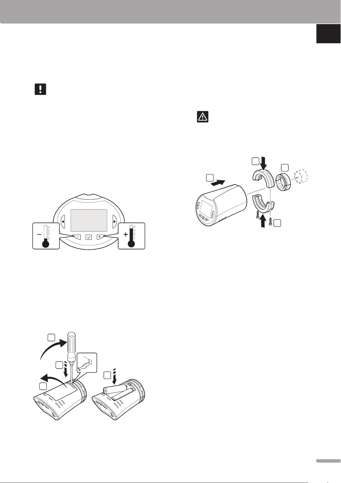
Adjust temperature
The room temperature setpoint is primarily adjusted
using a room thermostat.
In a room without a registered room thermostat the
temperature setpoint is adjusted on the thermostatic
head.
QUICK GUIDE
Install thermostatic head on hydraulic radiator
The thermostatic heads are delivered in kits including
adapters, plastic brackets, and screws.
Ca ut io n!
The thermostatic head must be installed on
a radiator before registering it to a controller.
Because the thermostatic head will perform a
valve stroke calibration, when registered, to
accurately operate the valve on the radiator.
1
2
EN
CZ
DE
DK
EE
ES
FI
FR
HR
Installation
The thermostatic head can be installed in rooms with
(setpoint from thermostatic head) or without a room
thermostat (setpoint from thermostat).
Insert batteries
The thermostatic head will perform a self test, for about
10 seconds, when the batteries have been inserted. The
system will be blocked for input.
2
1.4 mm
4 mm
1
4
4
To install a thermostatic head on a hydraulic radiator:
1. Mount the adaptor on the hydraulic radiator.
Threaded M28 or M30 adaptors are delivered with
the thermostatic head.
2. Hold the thermostatic head to he adaptor.
3. Fix the plastic brackets to the adaptor and
thermostatic head.
4. Fix the plastic brackets with the two screws.
HU
IT
LT
LV
NL
NO
PL
PT
RO
3
UPONOR SMATRIX WAVE THERMOSTATIC HEAD · QUICK GUIDE
RU
SE
SI
SK
5
Page 6
1
32
4
EN
CZ
DE
DK
EE
ES
FR
FI
QUICK GUIDE
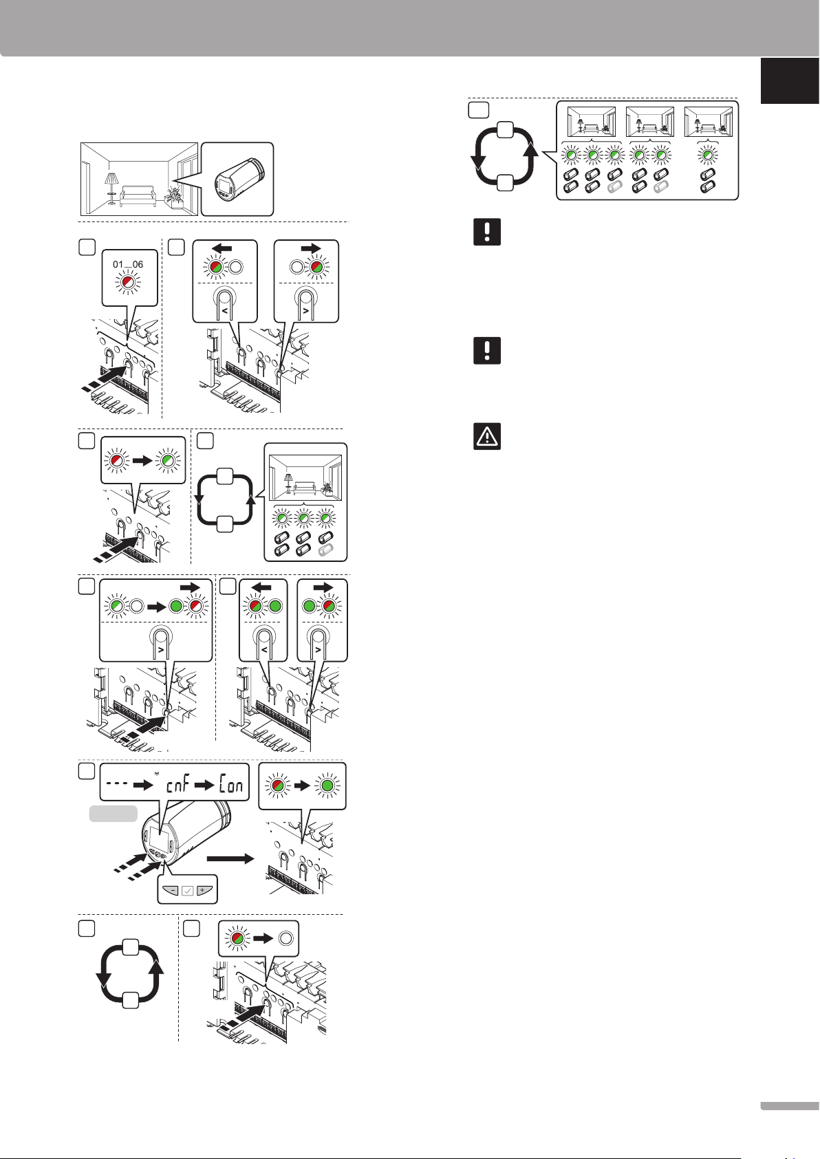
Register thermostatic heads to controller in rooms
with a thermostat
NOTE!
There is no indication showing if a
thermostatic head already is registered to a
channel.
Ca ut io n!
The thermostatic head must be installed on
a radiator before registering it to a controller.
Because the thermostatic head will perform a
valve stroke calibration, when registered, to
accurately operate the valve on the radiator.
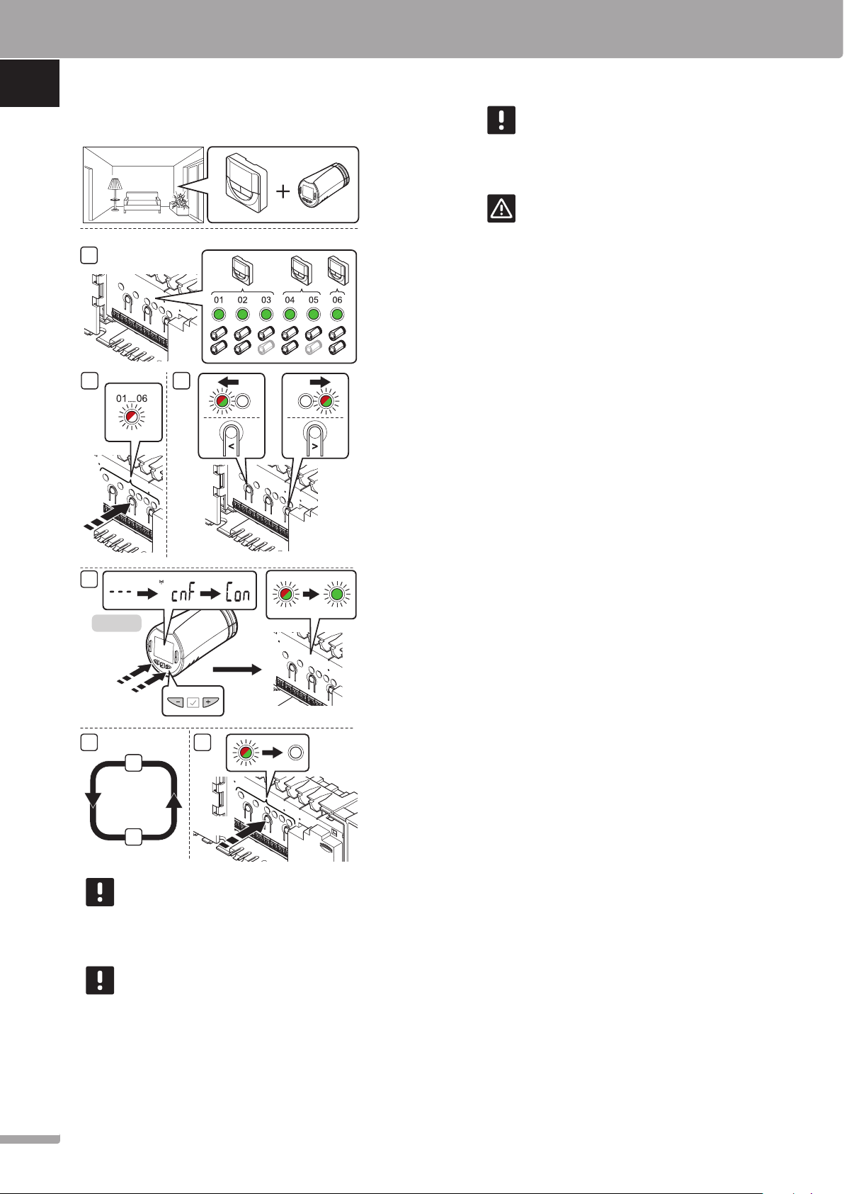
To register thermostatic heads in the controller:
1. A thermostat must be registered to a sufficient
number of channels to be able to control all
thermostatic heads in a room. A maximum of two
thermostatic heads can be registered per channel.
See section Uponor Smatrix Wave/Wave PLUS
documentation for more information.
2. Press and hold the OK button on the controller until
HR
3 s
HU
the LED for the first unregistered channel flashes
red. If all channels are registered to thermostats, the
LED flashes red and green.
3. Use buttons < or > to move the pointer (LED
flashes red) to the intended thermostat channel
(green LED). The LED flashed red and green.
IT
If the first channel is full, move the pointer to the
next thermostat channel in line.
LT
LV
NL
NO
PL
PT
RO
RU
SE
SI
T-162
5 s
5
6
3
4
NOTE!
The thermostat in control of the thermal
heads should not also control under floor
heating. Make notes to make sure
NOTE!
If two thermostatic heads already have been
registered to a channel, register the third to
the next channel in line. If more thermostat
channels are needed they can be added in
thermostat registration mode.
3 s
4. THERMOSTATIC HEAD T-162
4.1 Press and hold both - and + buttons on the
thermostatic head until the text CnF (configure)
and a communication icon is displayed.
The text Con is shown in the display, and the
selected channel LED in the controller turns
fixed green, when the registration is complete.
Note! If the text --- is shown in the
thermostatic head display the registration
failed. Repeat steps 2 through 3 and try
the next channel in line, in case two other
thermostatic heads already has been registered
to the current one.
5. Press one of the buttons on the controller and
repeat steps 3 through 4 until all thermostatic heads
are registered.
6. Press and hold the OK button on the controller
until the green LEDs turn off to end registration and
return to run mode.
SK
6
UPONOR SMATRIX WAVE THERMOSTATIC HEAD · QUICK GUIDE
Page 7
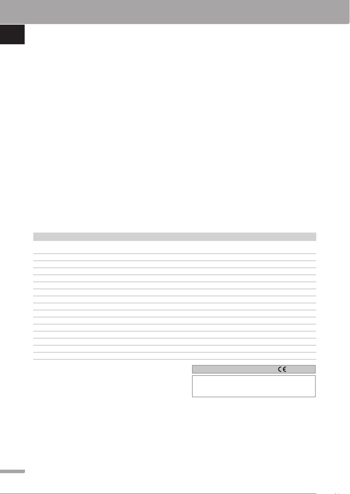
Register thermostatic heads to controller in rooms
21
7
10
without a thermostat
QUICK GUIDE
EN
1
CZ
3 s
3 4
5 6
9
NOTE!
If two thermostatic heads already have been
registered to a channel, register the third to
the next channel in line. If more thermostat
channels are needed they can be added in
thermostat registration mode.
DE
DK
EE
ES
NOTE!
There is no indication showing if a
thermostatic head already is registered to a
channel.
FI
FR
Ca ut io n!
The thermostatic head must be installed on
a radiator before registering it to a controller.
2
3
To register thermostatic heads in the controller:
1. Press and hold the OK button on the controller until
Because the thermostatic head will perform a
valve stroke calibration, when registered, to
accurately operate the valve on the radiator.
the LED for the first unregistered channel flashes
red. If all channels are registered to thermostats, the
LED flashes red and green.
HR
HU
IT
LT
2. Use buttons < or > to move the pointer (LED flashes
3 s
3 s
T-162
5 s
98
red) to the first empty channel needed for the room
(no LED). The LED flashed red.
3. Press the OK button to select the channel for
registration. The LED for the selected channel starts
flashing green.
4. Repeat steps 2 and 3 until a sufficient number of
channels for the room are created.
5. Press and hold the > button on the controller until
the selected channels light up green and the next
in line starts flashing red. A channel without a
thermostat has been created.
6. Use buttons < or > to move the pointer (LED
flashes red) to the first channel of the room (green
LED). The LED flashed red and green.
If the first channel is full, move the pointer to the
next channel in line.
LV
NL
NO
PL
PT
RO
RU
6
7
3 s
SE
SI
UPONOR SMATRIX WAVE THERMOSTATIC HEAD · QUICK GUIDE
SK
7
Page 8
EN
CZ
DE
DK
EE
ES
FR
FI
7. THERMOSTATIC HEAD T-162
7.1 Press and hold both - and + buttons on the
thermostatic head until the text CnF (configure)
and a communication icon is displayed.
The text Con is shown in the display, and the
selected channel LED in the controller turns
fixed green, when the registration is complete.
Note! If the text --- is shown in the
thermostatic head display the registration
failed. Repeat steps 2 through 3 and try
the next channel in line, in case two other
thermostatic heads already has been registered
to the current one.
8. Press one of the buttons on the controller and
repeat steps 6 through 7 until all thermostatic heads
are registered.
9. Press and hold the OK button on the controller
until the green LEDs turn off to end registration and
return to run mode.
QUICK GUIDE
Unregister a thermostatic head
When a thermostatic head is inaccurately registered, it
is possible to remove the current zone registration from
the controller.
To unregister a zone:
1. Enter registration mode. Channel 1 LED flashes red/
green, or the first unregistered channel flashes red.
2. Use buttons < or > to move the pointer (LED
flashes red) to the selected channel (flashes green if
registered) to unregister.
3. Press the < and > buttons simultaneously until the
LED for the selected channel starts flashing red
(about 5 seconds). All channels in the zone are
unregistered.
HR
HU
IT
LT
LV
NL
NO
PL
PT
RO
RU
10. Repeat steps 1 through 9 until the thermostatic
heads in all rooms are registered.
Technical data
Thermostatic head T-162
IP IP20 (IP: degree of inaccessibility to active parts of the product
and degree of water)
Max. ambient RH (relative humidity) 85% at 20 °C
CE marking
ERP (thermostat only) IV
Low voltage tests EN 60730-1* and EN 60730-2-9***
EMC (electromagnetic compatibility requirements) tests EN 60730-1 and EN 301-489-3
ERM (electromagnetic compatibility and radio spectrum matters) tests EN 300 220-3
Power supply Two 1.5 V AAA alkaline batteries
Voltage 2.2 V to 3.6 V
Maximum stroke 3.5 mm
Maximum strength 70 N
Differential pressure 1.5 bar
Operating temperature 0 °C to +40 °C
Storage temperature -10 °C to +50 °C
Radio frequency 868.3 MHz
Transmitter duty cycle <1%
*) EN 60730-1 Automatic electrical controls for household and similar use
-- Part 1: General requirements
**) EN 60730-2-1 Automatic electrical controls for household and similar use
-- Part 2-1: Particular requirements for electrical controls for electrical
household appliances
***) EN 60730-2-9 Automatic electrical controls for household and similar use
-- Part 2-9: Particular requirements for temperature sensing controls
Usable in all Europe
Declaration of conformity:
We hereby declare under our own responsibility that products dealt
with by these instructions satisfy all essential demands linked to the
R&TTE 1999/5/CE Directive dated March 1999.
SE
SI
SK
8
UPONOR SMATRIX WAVE THERMOSTATIC HEAD · QUICK GUIDE
Page 9

QUICK GUIDE
EN
CZ
DE
DK
EE
ES
FI
FR
HR
HU
IT
LT
LV
NL
NO
PL
PT
UPONOR SMATRIX WAVE THERMOSTATIC HEAD · QUICK GUIDE
RO
RU
SE
SI
SK
9
Page 10

1087357 07_2016_EN Production: Uponor AB, MRY, Virsbo; Sweden
Uponor Corporation
www.uponor.com
Uponor reserves the right to make changes, without prior notification,
to the specification of incorporated components in line with its policy
of continuous improvement and development.
 Loading...