

Page 1
12 | 2017
Uponor Smatrix
Wave
EN QUICK GUIDE
Page 2
Contents
Uponor Smatrix Wave components ..............................2
System example ................................................................2
Safety instructions .......................................................3
Controller ..........................................................................3
Thermostat/System device ...............................................3
Thermostatic Head ............................................................3
Quick Guide ...................................................................5
Installation ........................................................................5
Register thermostat and/or system device to a
controller...........................................................................7
Register thermostatic heads to controller in rooms
with a thermostat ..............................................................8
Register thermostatic heads to controller in rooms
without a thermostat ........................................................9
Unregister one channel or system device ........................10
Unregister all channels ....................................................10
Room bypass ...................................................................10
Other functions ...............................................................10
Technical data .............................................................11
Uponor Smatrix Wave
components
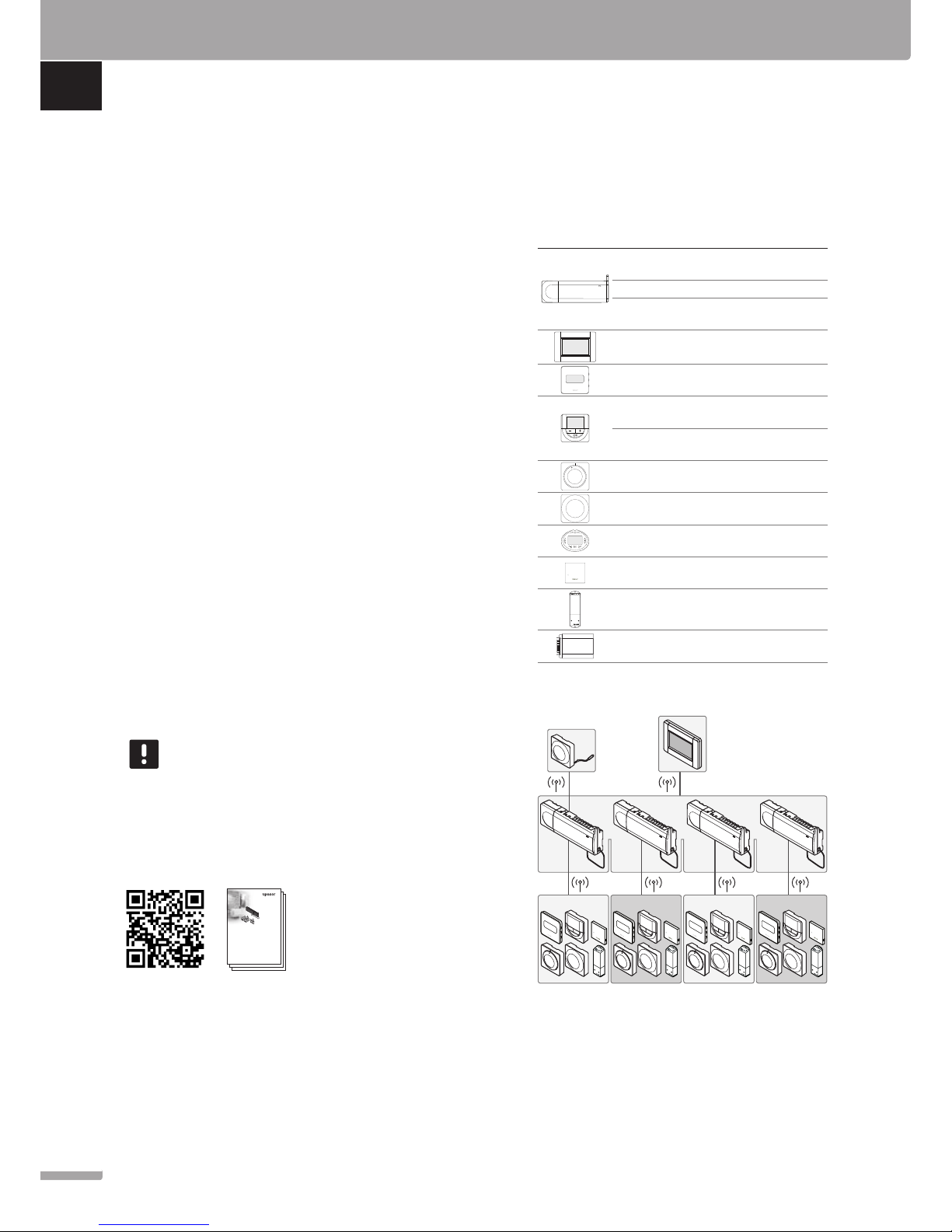
An Uponor Smatrix Wave system may be a combination
of the following components:
Uponor Smatrix Wave X-165 (controller)
Uponor Smatrix A-1XX (transformer A-1XX)
Uponor Smatrix Wave A-165
(antenna A-165)
Uponor Smatrix Wave I-167 (interface)
Uponor Smatrix Wave T-169
(digital thermostat T-169)
Uponor Smatrix Wave T-168
(digital thermostat T-168)
Uponor Smatrix Wave T-166
(digital thermostat T-166)
Uponor Smatrix Wave T-165
(standard thermostat T-165)
Uponor Smatrix Wave T-163
(public thermostat T-163)
Uponor Smatrix Wave T-162
(thermostatic head T-162)
Uponor Smatrix Wave T-161
(sensor thermostat T-161)
Uponor Smatrix Wave M-161
(relay module M-161)
Uponor Smatrix Wave M-160
(slave module M-160)
System example
1234
1234
NOTE!
This is a quick start guide to serve as a
reminder for experienced installers. We
strongly recommend reading the full manual
before installing the control system. See QR-
code for download link.
QUICK GUIDE
2
UPONOR SMATRIX WAVE · QUICK GUIDE
EN
CZ
DE
DK
EE
ES
FI
FR
HR
HU
IT
LT
LV
NL
NO
PL
PT
RO
RU
SE
SI
SK
Uponor Smatrix
Wave
UK INSTALLATION AND OPERATION
MANUAL
Uponor Smatrix
Wave
UK INSTALLATION AND OPERATION
MANUAL
Uponor Smatrix
Wave
UK INSTALLATION AND OPERATION
MANUAL
https://www.uponor.com/smatrix/downloads.aspx
Page 3
Safety instructions
This quick start guide to serves as a reminder for
experienced installers. We strongly recommend reading
the full manual before installing the control system.
Controller
Wa rn in g!
The Uponor system uses 50 Hz, 230 V AC
power. In case of emergency, immediately
disconnect the power.
Wa rn in g!
Electrical installation and service behind
secured 230 V AC covers must be carried
out under the supervision of a qualified
electrician.
Wa rn in g!
The transformer module is heavy and might
detach if the controller is held upside down
without the cover on.
Ca ut io n!
To avoid interference, keep installation/data
cables away from power cables of more than
50 V.
Ca ut io n!
If communication difficulties exist, Uponor
recommends relocating the antenna to a more
optimal position, and not installing Uponor
radio sources to close to each other (at
least 40 cm apart), for solving exceptional
problems.
Ca ut io n!
Ensure that each actuator is connected to the
correct channel so that the thermostats are
controlling the correct loops.
NOTE!
Wires between transformer and controller card
needs to be disconnected prior to detaching.
NOTE!
Connect only one actuator for each channel.
Channels 01 and 02 have double outputs (a
and b) for two actuators.
Thermostat/System device
NOTE!
Registration of at least one thermostat must
be done before registering a system device.
NOTE!
Up to four controllers can be registered to an
interface.
Ca ut io n!
If more than one controller is available in the
system, register the thermostat as a system
device to the master controller.
Ca ut io n!
The switches in public the thermostat must
be set before the thermostat is registered.
Ca ut io n!
The switches, in the public thermostat, must
be set to one of the available functions,
otherwise it cannot be registered.
Thermostatic Head
NOTE!
The thermostat in control of the thermal
heads should not also control under floor
heating. Make notes to make sure
NOTE!
If two thermostatic heads already have been
registered to a channel, register the third to
the next channel in line. If more thermostat
channels are needed they can be added in
thermostat registration mode.
NOTE!
There is no indication showing if a
thermostatic head already is registered to a
channel.
Ca ut io n!
The thermostatic head must be installed on
a radiator before registering it to a controller.
Because the thermostatic head will perform a
valve stroke calibration, when registered, to
accurately operate the valve on the radiator.
QUICK GUIDE
3
UPONOR SMATRIX WAVE · QUICK GUIDE
EN
CZ
DE
DK
EE
ES
FI
FR
HR
HU
IT
LT
LV
NL
NO
PL
PT
RO
RU
SE
SI
SK
Page 4
X-165
M-160*
T-163
X-165
M-160*
X-165
X-165
T-168
T-166
T-163
T-168
T-166
T-165
T-163
1
32
4 5
6 8
9
7
10
3 s
3 s
1 2 3 4
ON DIP
T-169
T-168
T-166
T-168
T-166
T-168
T-166
T-168
T-166
3.1
9.1
3.2
6.3
3.4
3.1
6.1
6.2
1.1
1.1
1.1
1.2
1.2
1.1
1.2
1.2
T-161
T-169
T-169
T-169 T-165 T-163T-161
T-161
T-169
3.3
T-169
1.2
04
6.2
6.2
6.1
6.1
9.2 9.2
9.3
9.4 9.4
9.5
*Option
*Option
Option
QUICK GUIDE
4
UPONOR SMATRIX WAVE · QUICK GUIDE
EN
CZ
DE
DK
EE
ES
FI
FR
HR
HU
IT
LT
LV
NL
NO
PL
PT
RO
RU
SE
SI
SK
Page 5
Quick Guide
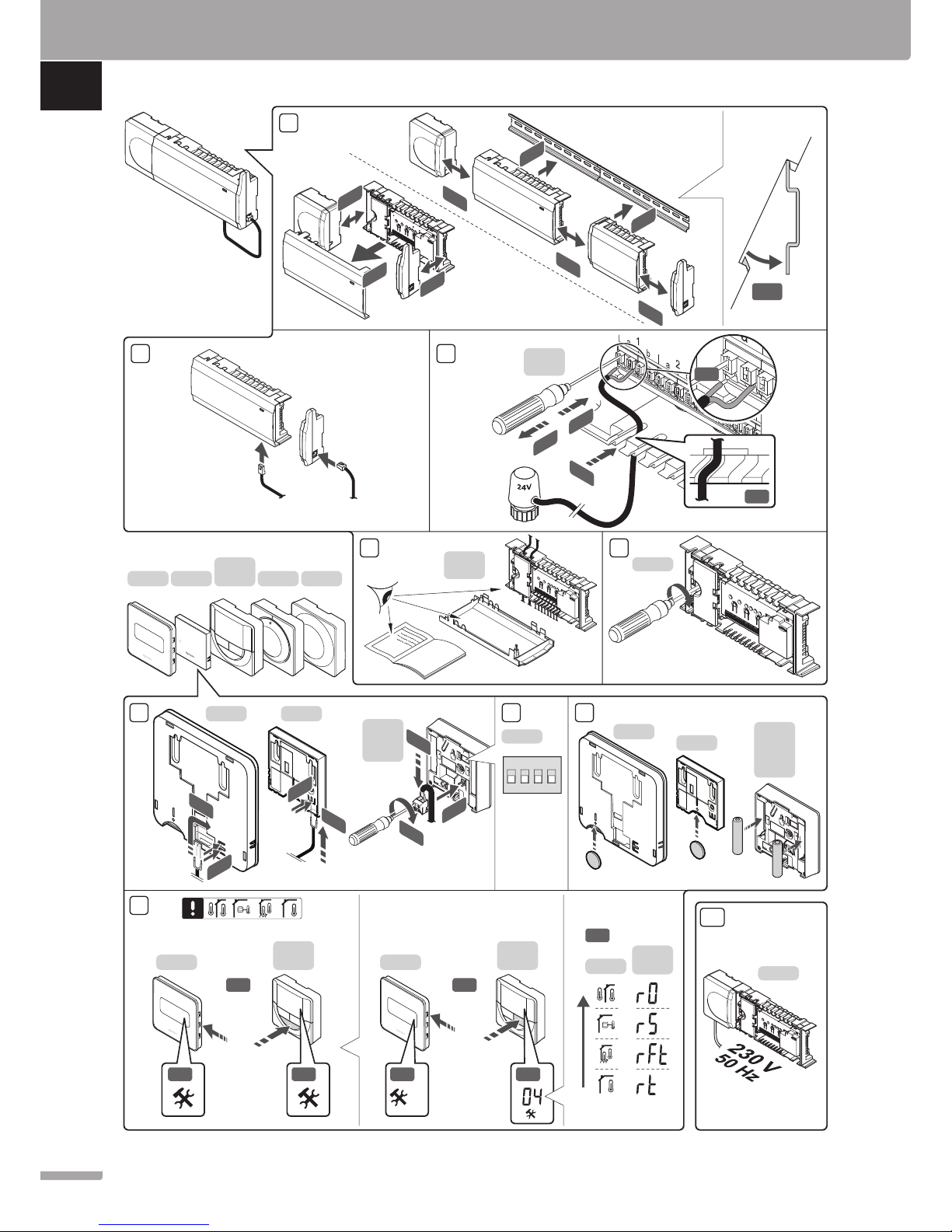
8. Insert batteries into the thermostats.
9. Select thermostat control mode (settings menu 04,
in digital thermostats only). Default: RT (standard
room thermostat).
10. Connect the power cable to a 230 V AC wall socket,
or if required by local regulations, to a junction box.
Register thermostats, the interface and other system
devices, in that order (next page).
Installation
1. Attach the full assembly, or parts of it, to the wall
either with a DIN rail or by using wall screws and
plugs.
If the controller is installed inside a metal cabinet,
then locate the antenna outside the cabinet.
2. Connect the antenna to the controller using the
supplied antenna cable (0.5 – 5m, CAT5e/CAT6).
3. Connect the actuators.
4. Check that all wiring is complete and correct:
• Actuators
• Heating/cooling switch
• Circulation pump
5. Ensure that the 230 V AC compartment of the
controller is closed and the fixing screw is tightened.
6. Connect optional external sensor (compatible
thermostats only).
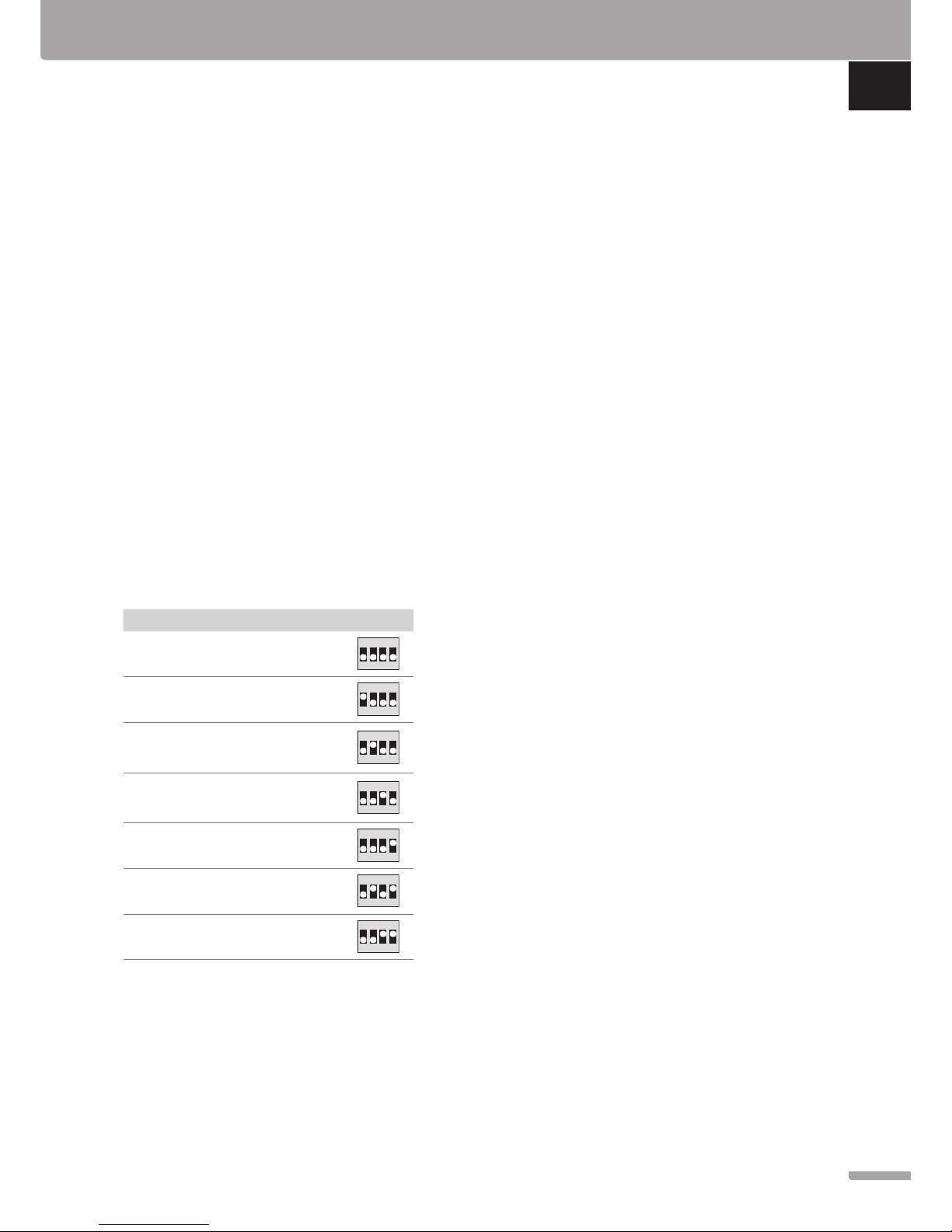
7. Set DIP switch on public thermostat T-163.
Function*
Switch
Standard room thermostat
1234
ON DIP
Standard room thermostat together with a
floor temperature sensor
1234
ON DIP
Standard room thermostat, or system device,
together with an outdoor temperature sensor
1234
ON DIP
System device together with a supply
temperature sensor for heating/cooling
switch over function
1234
ON DIP
System device where the sensor input is used
for Comfort/ECO switch over function
1234
ON DIP
Remote sensor
1234
ON DIP
System device where the sensor input is used
for heating/cooling switch-over function
1234
ON DIP
* The thermostat can only be registered as a system device to a
Wave system with multiple controllers, if it is registered to the
master controller.
QUICK GUIDE
5
UPONOR SMATRIX WAVE · QUICK GUIDE
EN
CZ
DE
DK
EE
ES
FI
FR
HR
HU
IT
LT
LV
NL
NO
PL
PT
RO
RU
SE
SI
SK
Page 6
11 12
13
13
14
15
15
12.1
12.1
12.1 12.3
5 s
5 s
5 s
12.2
3 s
5 s
T-166
T-168
T-163
T-169
T-161
T-165
5 s
16
17 18
18
15.1 15.2
15.4
I-167
M-161
English
Español
Português
Deutsch
Italiano
Français
Suomi
Svenska
01 02 03 04 05 06
16.1
16.2
16.3
16.1
15.3
3 s
15.3
5 s
T-163
I-167
M-161
T-163
T-169
T-168
T-166
T-165
T-163
T-161
11
Link OK
Link Touch Screen to controller
QUICK GUIDE
6
UPONOR SMATRIX WAVE · QUICK GUIDE
EN
CZ
DE
DK
EE
ES
FI
FR
HR
HU
IT
LT
LV
NL
NO
PL
PT
RO
RU
SE
SI
SK
Page 7

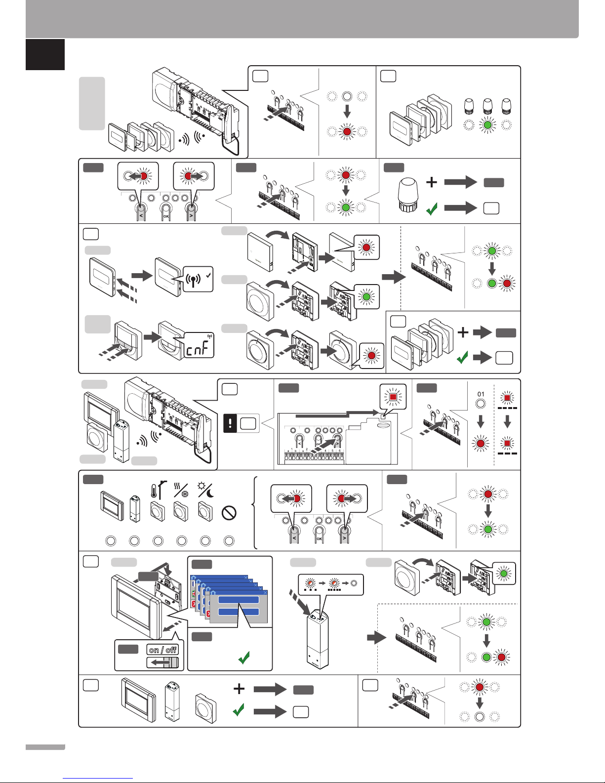
Register thermostat and/or system device
to a controller
To register room thermostats and system devices (interface
etc.) to the controller:
Enter registration mode
11. Press and hold the OK button on the controller, for
about 3 seconds, until the LED for channel 1 (or the
first unregistered channel) flashes red.
Register a thermostat
12. Select a thermostat channel.
12.1 Use buttons < or > to move the pointer (LED
flashes red) to a preferred channel.
12.2 Press the OK button to select the channel for
registration. The LED for the selected channel
starts flashing green.
12.3 Repeat steps 12.1 and 12.2 until all channels to
be registered with the thermostat are selected
(LEDs flashing green).
Note! It is recommended to register all channels
to the thermostat at the same time.
13. Select a thermostat.
THERMOSTAT T-163 AS A THERMOSTAT, WITH
VARIOUS FUNCTIONS
13.1 Gently press and hold the registration button
on the thermostat, release when the LED starts
flashing green (located in the hole above the
registration button).
The selected channel LED in the controller turns
fixed green and the registration is complete.
THERMOSTAT T-161 AND T-165
13.1 Gently press and hold the registration button
on the thermostat, release when the LED on the
front of the thermostat starts flashing.
The selected channel LED in the controller turns
fixed green and the registration is complete.
THERMOSTATS T-166, T-168 AND T-169
13.1 Press and hold both - and + buttons (T-169
= and ) on the thermostat until the text
CnF (configure) and a communication icon is
displayed.
The selected channel LED in the controller turns
fixed green and the registration is complete.
14. Repeat steps 12 and 13 until all available thermostats
are registered.
Register a system device (I-167 etc)
NOTE!
At least one thermostat must be registered before
registering a system device.
15. Make sure to be in registration mode (step 11).
15.1 Use buttons < or > to move the pointer to the
power LED (LED flashes red).
15.2 Press the OK button to enter system channel
registration mode. The power LED flashes
according to the pattern long blink, short pause,
long blink and channel 1 LED flashes red.
15.3 Select a system channel, see list below.
1 = Touch screen interface
2 = Relay module
3 = Public thermostat with outdoor sensor
4 = Public thermostat with heating/cooling
switch from contact or sensor input
5 = Public thermostat with Comfort/ECO switch
15.4 Press the OK button to select system device
channel. The channel LED starts flashing green.
16. Select a system device matching the system channel.
INTERFACE I-167
16.1. Power up the interface and attach it to the
charger.
16.2. Follow the startup guide in the interface up until
registration.
16.3 Press Link Touch Screen to controller in the
Startup guide, or RF Link menu (Main menu >
Preferences), to initialize registration.
16.4 The interface gets registered to the controller.
The selected channel LED in the controller turns
fixed green and the registration is complete.
RELAY MODULE M-161
16.1 Press and hold the register button on the relay
module until the LEDs on the module start
flashing slowly.
The selected channel LED in the controller turns
fixed green and the LEDS on the relay module
start flashing fast again, to turn off a few seconds
later.
THERMOSTAT T-163 AS A SYSTEM DEVICE, WITH
VARIOUS FUNCTIONS
16.1 Gently press and hold the registration button
on the thermostat, release when the LED starts
flashing green (located in the hole above the
registration button).
The selected channel LED in the controller turns
fixed green and the registration is complete.
17. Repeat steps 15 and 16 until all available system devices
are registered.
Exit registration mode
18. Press and hold the OK button on the controller, for
about 3 seconds, until the green LEDs turn off to end
registration and return to run mode.
QUICK GUIDE
7
UPONOR SMATRIX WAVE · QUICK GUIDE
EN
CZ
DE
DK
EE
ES
FI
FR
HR
HU
IT
LT
LV
NL
NO
PL
PT
RO
RU
SE
SI
SK
Page 8
Register thermostatic heads to controller
in rooms with a thermostat
1
4
2 3
5 6
5 s
3 s
3 s
3
6
T-162
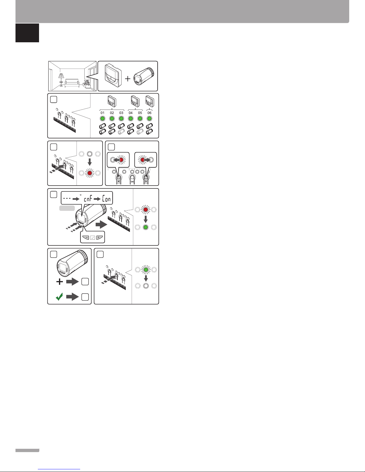
To register thermostatic heads in the controller:
1. A thermostat must be registered to a sufficient
number of channels to be able to control all
thermostatic heads in a room. A maximum of two
thermostatic heads can be registered per channel.
See section Uponor Smatrix Wave documentation
for more information.
2. Press and hold the OK button on the controller until
the LED for the first unregistered channel flashes
red. If all channels are registered to thermostats, the
LED flashes red and green.
3. Use buttons < or > to move the pointer (LED
flashes red) to the intended thermostat channel
(green LED). The LED flashed red and green.
If the first channel is full, move the pointer to the
next thermostat channel in line.
4. THERMOSTATIC HEAD T-162
4.1 Press and hold both - and + buttons on the
thermostatic head until the text CnF (configure)
and a communication icon is displayed.
The text Con is shown in the display, and the
selected channel LED in the controller turns
fixed green, when the registration is complete.
Note! If the text --- is shown in the
thermostatic head display the registration
failed. Repeat steps 2 through 3 and try
the next channel in line, in case two other
thermostatic heads already has been registered
to the current one.
5. Press one of the buttons on the controller and
repeat steps 3 through 4 until all thermostatic heads
are registered.
6. Press and hold the OK button on the controller
until the green LEDs turn off to end registration and
return to run mode.
QUICK GUIDE
8
UPONOR SMATRIX WAVE · QUICK GUIDE
EN
CZ
DE
DK
EE
ES
FI
FR
HR
HU
IT
LT
LV
NL
NO
PL
PT
RO
RU
SE
SI
SK
Page 9
Register thermostatic heads to controller
in rooms without a thermostat
5
1
4
2
6 7
5 s
3 s
3 s
3 s
4
7
2
3
T-162
3
8
1
2.1
2.3
2.2
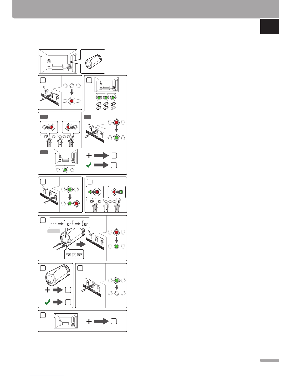
To register thermostatic heads in the controller:
1. Press and hold the OK button on the controller until
the LED for the first unregistered channel flashes
red. If all channels are registered to thermostats, the
LED flashes red and green.
2. Select a thermostat channel.
2.1 Use buttons < or > to move the pointer (LED
flashes red) to the first empty channel needed
for the room (no LED). The LED flashed red.
2.2 Press the OK button to select the channel for
registration. The LED for the selected channel
starts flashing green.
2.3 Repeat steps 2.1 and 2.2 until a sufficient number
of channels for the room are created.
3. Press and hold the > button on the controller until
the selected channels light up green and the next
in line starts flashing red. A channel without a
thermostat has been created.
4. Use buttons < or > to move the pointer (LED
flashes red) to the first channel of the room (green
LED). The LED flashed red and green.
If the first channel is full, move the pointer to the
next channel in line.
5. THERMOSTATIC HEAD T-162
5.1 Press and hold both - and + buttons on the
thermostatic head until the text CnF (configure)
and a communication icon is displayed.
The text Con is shown in the display, and the
selected channel LED in the controller turns
fixed green, when the registration is complete.
Note! If the text --- is shown in the
thermostatic head display the registration
failed. Repeat steps 2.1 through 2.2 and try
the next channel in line, in case two other
thermostatic heads already has been registered
to the current one.
6. Press one of the buttons on the controller and
repeat steps 4 through 5 until all thermostatic heads
are registered.
7. Press and hold the OK button on the controller
until the green LEDs turn off to end registration and
return to run mode.
8. Repeat steps 1 through 7 until the thermostatic
heads in all rooms are registered.
QUICK GUIDE
9
UPONOR SMATRIX WAVE · QUICK GUIDE
EN
CZ
DE
DK
EE
ES
FI
FR
HR
HU
IT
LT
LV
NL
NO
PL
PT
RO
RU
SE
SI
SK
Page 10

Register multiple controllers
Up to four controllers can be registered to an interface.
All additional controllers in the system must be
registered to the interface.
NOTE!
At least one thermostat must be registered to
the additional controller before registering to
the interface.
See steps 15 and 16 in the “Register thermostat and/
or system device to a controller” section for more
information.
Unregister one channel or system device
When a channel or system device is inaccurately
registered or if a thermostat registration needs to be
redone, it is possible to remove the current registration
from the controller.
NOTE!
The controller must be unregistered in the
interface as well. Go to menu Main menu >
Preferences > RF Link and unregister.
To unregister a channel:
1. Enter registration mode. Channel 1 LED flashes red/
green, or the first unregistered channel flashes red.
2. If a system device (interface etc) is to be
unregistered, enter system channel registration
mode. The power LED flashes according to the
pattern long blink, short pause, long blink and
channel 1 LED flashes red/green.
3. Use buttons < or > to move the pointer (LED
flashes red) to the selected channel (flashes green if
registered) to unregister.
4. Press the < and > buttons simultaneously until the
LED for the selected channel starts flashing red
(about 5 seconds).
Unregister all channels
When one or more channels (thermostats and system
devices) are inaccurately registered, it is possible to
remove all registrations at the same time.
NOTE!
The controller must be unregistered in the
interface as well. Go to menu Main menu >
Preferences > RF Link and unregister.
To cancel all channel registrations:
1. Enter registration mode. Channel 1 LED flashes red/
green, or the first unregistered channel flashes red.
2. Press the < and > buttons simultaneously until the
LEDs for all channels except one turn off (about
10 seconds). The one remaining flashes red.
Room bypass
To reach the bypass settings, the controller must be
registered to the interface.
1. In the interface, go to the Room bypass menu,
Main menu > System settings > Room bypass.
2. Select a controller.
3. Select up to a maximum of two rooms.
4. Press the Confirm button to save and exit the
menu.
Other functions
See full manual for more information about
Autobalancing of actuators (eliminating the need
of manual balancing,on by default), Heat pump
integration, Cooling, Comfort/ECO settings, Smart
Home Gateway, Room check, and Supply check etc.
QUICK GUIDE
10
UPONOR SMATRIX WAVE · QUICK GUIDE
EN
CZ
DE
DK
EE
ES
FI
FR
HR
HU
IT
LT
LV
NL
NO
PL
PT
RO
RU
SE
SI
SK
Page 11
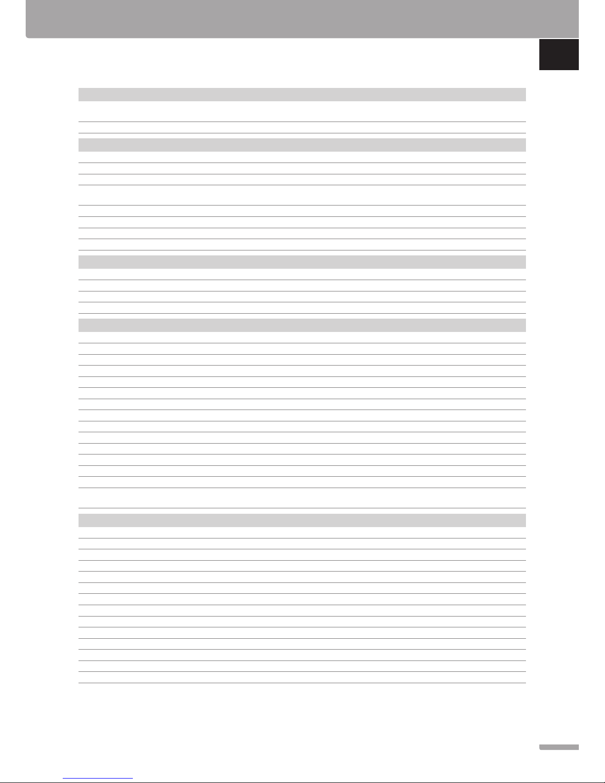
Technical data
General
IP IP20 (IP: degree of inaccessibility to active parts of the product
and degree of water)
Max. ambient RH (relative humidity) 85% at 20 °C
Interface
CE marking
Low voltage tests EN 60730-1 and EN 60730-2-1
EMC (electromagnetic compatibility requirements) tests EN 60730-1
Power supply 230 V AC +10/-15%, 50 Hz in wall box or
mini USB connection
Operating temperature 0 °C to +45 °C
Storage temperature -20 °C to +70 °C
Radio frequency 868.3 MHz
Transmitter duty cycle <1%
Antenna
Power supply From controller
Radio frequency 868.3 MHz
Transmitter duty cycle <1%
Receiver class 2
Thermostat
CE marking
ERP IV
Low voltage tests EN 60730-1* and EN 60730-2-9***
EMC (electromagnetic compatibility requirements) tests EN 60730-1 and EN 301-489-3
ERM (electromagnetic compatibility and radio spectrum matters) tests EN 300 220-3
Power supply (T-163, T-165, T-166, and T-168) Two 1.5 V AAA alkaline batteries
Power supply (T-161 and T-169) 1 x CR2032 3V
Voltage (T-163, T-165, T-166, and T-168) 2.2 V to 3.6 V
Voltage (T-161 and T-169) 2.4 V to 3.6 V
Operating temperature 0 °C to +45 °C
Storage temperature -10 °C to +65 °C
Radio frequency 868.3 MHz
Transmitter duty cycle <1%
Connection terminals (T-163, T-165, T-166, and T-168) 0.5 mm² to 2.5 mm²
Connection terminals (T-161 and T-169) 0.25 mm² to 0.75 mm² solid, or 0.34 mm² to 0.5 mm² flexible
with ferrules
Relay module
CE marking
ERP IV
Low voltage tests EN 60730-1* and EN 60730-2-1**
EMC (electromagnetic compatibility requirements) tests EN 60730-1 and EN 301-489-3
ERM (electromagnetic compatibility and radio spectrum matters) tests EN 300 220-3
Power supply 230 V AC +10/-15%, 50 Hz or 60 Hz
Operating temperature 0 °C to +50 °C
Storage temperature -20 °C to +70 °C
Maximum consumption 2 W
Radio frequency 868.3 MHz
Transmitter duty cycle <1%
Relay outputs 230 V AC +10/-15%, 250 V AC 2.5 A maximum
Power connection 1 m cable with europlug (except UK)
Connection terminals Up to 4.0 mm² solid, or 2.5 mm² flexible with ferrules
QUICK GUIDE
11
UPONOR SMATRIX WAVE · QUICK GUIDE
EN
CZ
DE
DK
EE
ES
FI
FR
HR
HU
IT
LT
LV
NL
NO
PL
PT
RO
RU
SE
SI
SK
Page 12
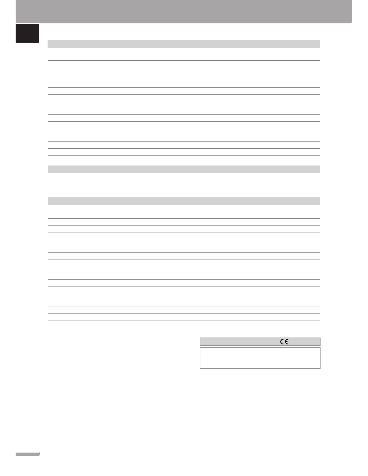
Thermostatic head T-162
IP IP20 (IP: degree of inaccessibility to active parts of the product
and degree of water)
Max. ambient RH (relative humidity) 85% at 20 °C
CE marking
ERP (thermostat only) IV
Low voltage tests EN 60730-1* and EN 60730-2-9***
EMC (electromagnetic compatibility requirements) tests EN 60730-1 and EN 301-489-3
ERM (electromagnetic compatibility and radio spectrum matters) tests EN 300 220-3
Power supply Two 1.5 V AAA alkaline batteries
Voltage 2.2 V to 3.6 V
Maximum stroke 3.5 mm
Maximum strength 70 N
Differential pressure 1.5 bar
Operating temperature 0 °C to +40 °C
Storage temperature -10 °C to +50 °C
Radio frequency 868.3 MHz
Transmitter duty cycle <1%
Controller/interface SD card
Type micro SDHC, UHS or Standard
Capacity 4 GB to 32 GB, FAT 32 formatting
Speed Class 4 to 10 (or higher)
Controller
CE marking
ERP VIII
Low voltage tests EN 60730-1* and EN 60730-2-1***
EMC (electromagnetic compatibility requirements) tests EN 60730-1 and EN 301-489-3
ERM (electromagnetic compatibility and radio spectrum matters) tests EN 300 220-3
Power supply 230 V AC +10/-15%, 50 Hz or 60 Hz
Internal fuse T5 F3.15AL 250 V, 5x20 3.15A quick acting
Internal fuse, Heat pump output TR5-T 8.5 mm Wickmann 100 mA Time lag
Operating temperature 0 °C to +45 °C
Storage temperature -20 °C to +70 °C
Maximum consumption 45 W
Pump and boiler relay outputs 230 V AC +10/-15%, 250 V AC 8 A maximum
General purpose input (GPI) Only dry contact
Heat pump input 12 – 24 V DC /5 – 20 mA
Heat pump output 5 – 24 V DC /0.5 – 10 mA, current sink ≤ 100 mW
Valve outputs 24 V AC, 4 A max.
Power connection 1 m cable with europlug (except UK)
Connection terminals for power, pump, GPI and boiler Up to 4.0 mm² solid, or 2.5 mm² flexible with ferrules
Connection terminals for valve outputs 0.2 mm² to 1.5 mm²
*) EN 60730-1 Automatic electrical controls for household and similar use
-- Part 1: General requirements
**) EN 60730-2-1 Automatic electrical controls for household and similar use
-- Part 2-1: Particular requirements for electrical controls for electrical
household appliances
***) EN 60730-2-9 Automatic electrical controls for household and similar use
-- Part 2-9: Particular requirements for temperature sensing controls
Usable in all Europe
Declaration of conformity:
We hereby declare under our own responsibility that products dealt
with by these instructions satisfy all essential demands linked to the
information stated in the Safety instruction booklet.
QUICK GUIDE
12
UPONOR SMATRIX WAVE · QUICK GUIDE
EN
CZ
DE
DK
EE
ES
FI
FR
HR
HU
IT
LT
LV
NL
NO
PL
PT
RO
RU
SE
SI
SK
Page 13
QUICK GUIDE
13
UPONOR SMATRIX WAVE · QUICK GUIDE
EN
CZ
DE
DK
EE
ES
FI
FR
HR
HU
IT
LT
LV
NL
NO
PL
PT
RO
RU
SE
SI
SK
Page 14

Uponor Corporation
www.uponor.com
Uponor reserves the right to make changes, without prior notification,
to the specification of incorporated components in line with its policy
of continuous improvement and development.
1091824 12_2017_EN Production: Uponor AB, MRY, Virsbo; Sweden
 Loading...