

Page 1
RADIANT HEATING SYSTEMS
UPONOR CLIMATE
C O˘NTROL™ NETWORK
SYSTEM THERMOSTAT
INSTALLATION AND
OPERATION GUIDE
Uponor Climate Co˘ntrol™ Network System
Thermostat Installation and Operation Guide
Page 2

Uponor Climate Co˘ntrol Network™ System
Thermostat Installation and Operation Guide
Published by Uponor
5925 148th Street West
Apple Valley, MN 55124 USA
Phone: (800) 321-4739
Fax: (952) 891-1409
Uponor, Ltd.
655 Park Street
Regina, SK S4N 5N1 CANADA
Phone: (888) 994-7726
Fax: (800) 638-9517
www.uponor-usa.com
www.uponor.ca
© 2008 Uponor
All Rights Reserved.
First Edition
First Printing, May 2008
Printed in the United States of America
2
www.uponor-usa.com • www.uponor.ca
Page 3

Table of Contents
Section 1 — Uponor Climate Co˘ntrol™
Network System Thermostat Overview . . . . . . . . . . . . . . 5
Getting Ready. . . . . . . . . . . . . . . . . . . . . . . . . . . . 5
Section 2 — Installation Methods . . . . . . . . . . . . . . . . 7
Mounting Thermostat. . . . . . . . . . . . . . . . . . . . . . . . . 7
Surface Mount . . . . . . . . . . . . . . . . . . . . . . . . . . 7
Flush Mount. . . . . . . . . . . . . . . . . . . . . . . . . . . 8
Wiring Thermostat . . . . . . . . . . . . . . . . . . . . . . . . . .9
Tools Required . . . . . . . . . . . . . . . . . . . . . . . . . . 9
Power and Data Wiring. . . . . . . . . . . . . . . . . . . . . . . 9
Placing the Slab Sensor . . . . . . . . . . . . . . . . . . . . . . . . 9
Wiring the Slab Sensor . . . . . . . . . . . . . . . . . . . . . . . 9
Section 3 — Operation. . . . . . . . . . . . . . . . . . . . . . . . . 11
Setting the Zone Number . . . . . . . . . . . . . . . . . . . . . . 11
Setting the Primary Heating Method . . . . . . . . . . . . . . . . . . 11
Setting the Secondary Heating Method . . . . . . . . . . . . . . . . . 11
Setting the Radiant Heating Water Temperature Channel . . . . . . . . . . 12
Setting Which Zone Pump the Thermostat is Controlling . . . . . . . . . . 12
Setting Which Zone Valve the Thermostat is Controlling . . . . . . . . . . 12
Setting the Air Zone . . . . . . . . . . . . . . . . . . . . . . . . 12
Setting the Air Water Temperatures . . . . . . . . . . . . . . . . . . 12
Setting the Air Water Zone Pump . . . . . . . . . . . . . . . . . . . 13
Setting the Air Water Zone Valve . . . . . . . . . . . . . . . . . . . 13
Setting the Air Damper Number . . . . . . . . . . . . . . . . . . . . 13
Setting the Air Handler Number . . . . . . . . . . . . . . . . . . . . 13
Setting the Heat Recovery Ventiliator (HRV) Number . . . . . . . . . . . 14
Setting the Supplementary Water Temperature Channel Number . . . . . . . 14
Setting the Supplementary Zone Pump . . . . . . . . . . . . . . . . . 14
Setting the Supplementary Zone Valve . . . . . . . . . . . . . . . . . 14
Setting the Auto Schedule Number . . . . . . . . . . . . . . . . . . 14
Setting the Temperature Offset . . . . . . . . . . . . . . . . . . . . 15
Viewing the Thermostat Software Revision . . . . . . . . . . . . . . . 15
Section 4 — Wiring Diagram . . . . . . . . . . . . . . . . . . . . 17
Uponor Climate Co˘ntrol™ Network System Thermostat Installation and Operation Guide
3
Page 4

4
www.uponor-usa.com • www.uponor.ca
Page 5

Section 1 —
Uponor Climate Co˘ntrol™ Network System
Thermostat Overview
The Uponor Climate C˘ontrol™ Network System Thermostat is
designed specically to function
within the network control system.
The thermostat is available in two
models — vertical and horizontal —
and displays air, slab, humidity and
outdoor temperatures. The thermostat
controls two stages of heat, two
stages of cooling and supplemental
heat all via a single pair of thermostat
wires (18-22 AWG).
The user can change the display,
modes, temperature setpoint, humidity setpoint, fan and heat recovery
ventilator (HRV) from any thermostat
in the control system. The thermostat
also offers an optional feature called
master passing. This is an optional
feature that changes HVAC control
of a room to the current thermostat
being manually adjusted.
This manual provides standard
installation and operation procedures
for the thermostat. A list of terms
commonly used in this manual is
provided below.
Getting Ready
Check the contents of the thermostat
package (see Table 1-1). If any of
the contents are missing or damaged,
contact your Uponor sales representative
or distributor for assistance.
Term Denition
Draft barrier A material that blocks or is intended to
block air passage
DZCM Digital Zone Control Module
HRV Abbreviation for heating recovery ventilator
HVAC Heating, ventilation and air conditioning
Master passing An optional feature that changes HVAC
control of a room to the current thermostat
being manually adjusted
PEX Abbreviation for crosslinked polyethylene.
Setpoint This refers to the desired thermostat setting.
The room setpoint temperature is the target
temperature for the room.
Slab This refers to a concrete slab under which
radiant heating has been installed.
Temperature Offset Setpoint that serves to counterbalance the
primary setpoint for the target temperature
Zone An area of a radiant panel served by one
or more loops and individually controlled
through a thermostat
Thermostat Style Package Contents
Surface Mount
(A9010510)
Flush Mount Vertical
(A9010520)
Flush Mount Horizontal
(A9010530)
• One thermostat
• One case front
• One case back
• Two #4 screws (for attaching the case to the case back)
• User manual
• One thermostat
• Flush-mount skin
• Mounting wings
• #4 screws (for attaching the mounting wings to the case)
• User manual
Table 1-1: Thermostat Package Contents
Uponor Climate Co˘ntrol™ Network System Thermostat Installation and Operation Guide
5
Page 6

6
www.uponor-usa.com • www.uponor.ca
Page 7

Section 2 –
Installation Methods
Mounting the
Thermostat
Install the thermostat on an
interior wall of the desired zone,
approximately 5 feet (1.5 meters)
above the oor. Do not mount the
thermostat in a location that may
be affected by heat sources or cold
drafts. If necessary, install a draft
barrier behind the control to prevent
air from blowing through the wiring
hole and affecting the control’s
built-in sensor.
Avoid mounting the thermostat
in the following locations:
• Near or around windows
• On outside walls
• Near replaces
• In the corner of a room
• Behind doors
• Near dimming switches
• On interior walls susceptible
to solar gains
• Near stoves, lamps, televisions,
computer monitors, etc.
• In damp or humid areas
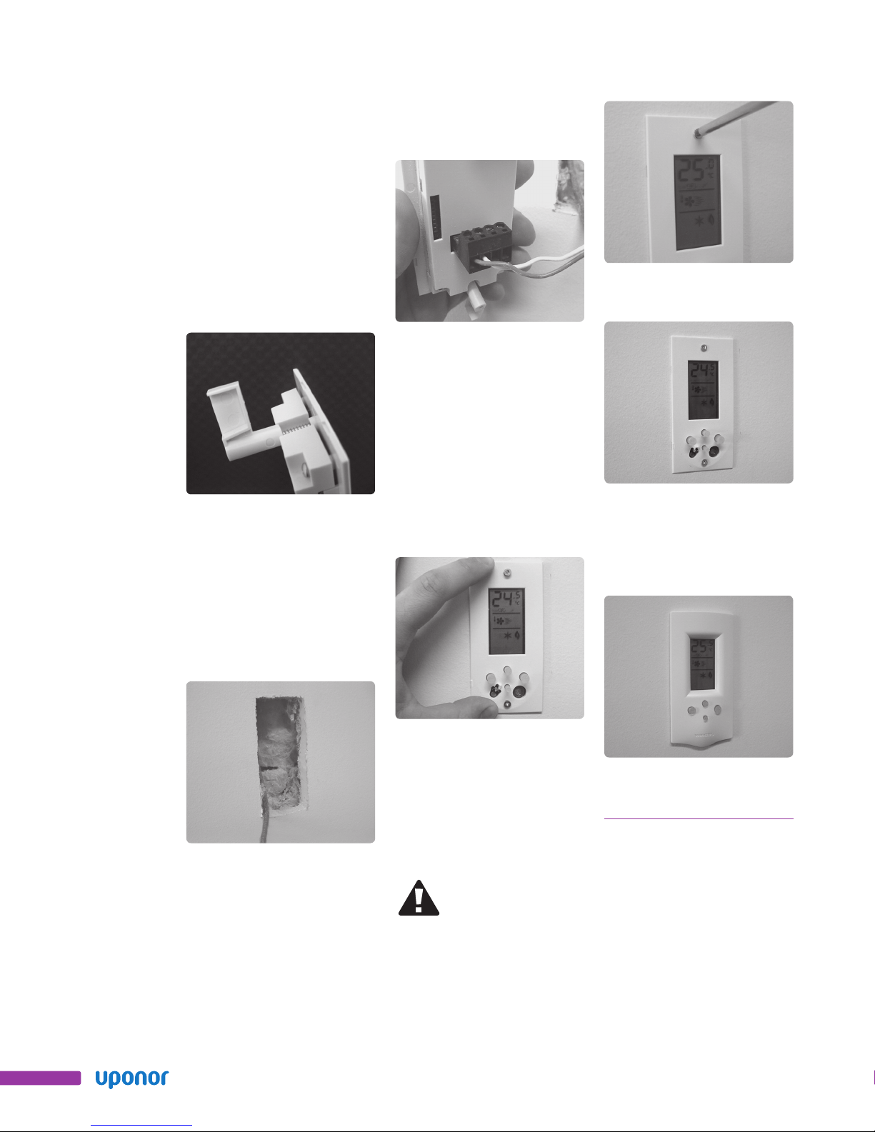
Figure 2-1: Case back of
thermostat being mounted
on wall
3. Insert drywall anchors into the
wall at the marked locations
and cut out a hole in the wall to
receive the main connector.
5. Wire the thermostat. Refer to
Section 2: Wiring the Thermostat
and Section 4: Wiring Diagram.
Figure 2-4: Wiring
thermostat procedure
6. Use the supplied #4 screws to
mount the thermostat into the
case back.
Surface Mount
The following steps outline how to
mount the surface-mount thermostat.
1. Locate an area to mount the
thermostat.
2. Place case back on the wall and
mark areas for the screw and
connector holes with a pencil.
Uponor Climate Co˘ntrol™ Network System Thermostat Installation and Operation Guide
Figure 2-2: Inserting
drywall anchors
4. Using appropriate screws (not
included), attach the case back
to the drywall anchors.
Figure 2-3: Case back of
thermostat procedure
Figure 2-5: Mount
thermostat procedure
7. Snap the case front into place
on the case back.
Figure 2-6: Mount
thermostat procedure
7
Page 8
Flush Mount
The following steps outline how to
mount the ush-mount thermostat.
Note: The ush-mount thermostat
is designed for mounting in ½inch drywall.
1. Loosely attach the wings into
the back of the thermostat with
the supplied hardware as shown
in Figure 2-7. (Only tighten
the screws one or two turns
into the wings.)
Figure 2-7: Flush
mount thermostat
2. Use the template provided to
mark the cutout in the drywall
for the thermostat. Use a level
to ensure the cutout is straight.
3. Cut around your marking with
a drywall saw or utility knife.
4. Wire the thermostat. Refer to
Section 2: Wiring the Thermostat
and Section 4: Wiring Diagram.
Figure 2-9: Flush
mount thermostat
5. Push in any insulation and cut
away any excess drywall or paper
to ensure nothing interferes with
the action on the wings. The
thermostat will not mount correctly
if there is any interference.
6. Place the thermostat in the hole
in the drywall and hold it tight
against the wall.
Figure 2-11: Flush
mount thermostat
Figure 2-12: Flush
mount thermostat
8. Snap the ush-mount thermostat
skin into place on the thermostat.
Figure 2-8: Flush
mount thermostat
8
Figure 2-10: Flush
mount thermostat
Figure 2-13: Flush
7. Turn the wing screws slowly.
Initially, the wings will turn 90
degrees behind the drywall. As
you continue tightening, they will
secure the thermostat in place.
Important: Do not overly
tighten the wings.
mount thermostat
www.uponor-usa.com • www.uponor.ca
Page 9

Wiring the
Thermostat
The following steps outline how
to wire the thermostat.
Note: All wiring must comply
with local electrical codes
and specications. Uponor
recommends 18 AWG LVT or
similar wire for all thermostat
connections. Strip all wires to
¼” (6.3 mm) to ensure proper
connection to thermostat
terminal blocks. If an optional
sensor is used (e.g., a slab
sensor), run a single-pair,
18 AWG wire from the sensor
to the control.
Wiring the Slab Sensor
Connect the two wires from the
sensor to the slab sensor terminals
on the thermostat as shown in
Figure 2-15. In this case, polarity
does not matter.
Tools Required
• Small, at-head screwdriver
• Phillips screwdriver
• Wire cutter and stripper
Caution: To prevent
damage to the thermostat,
do not connect it to 24-volt
control systems or devices
other than the Digital Zone
Control Module (DZCM).
Power and Data Wiring
1. Refer to the DZCM Installation
Guide for wiring to the DZCM.
2. Run a single-pair, 18 AWG LVT
wire from the DZCM to the
thermostat.
3. Attach the wires to the Pwr/
Comm terminals shown in
Figure 2-14.
Note: Be sure to observe the
thermostat’s polarity and wire
color. Use the red wire to
connect the positive terminal on
the thermostat to the positive
terminal on the controller.
Figure 2-14 Power
and data wiring
Placing the
Slab Sensor
The following steps outline how to
install a slab sensor.
1. Place the slab sensor between
two PEX tubes in the oor.
2. If the oor is wood construction,
place the sensor as close to
the oor surface as possible.
If the oor is concrete or like
construction, place the sensor
no deeper than the mid-point
of the slab.
3. Uponor recommends placing
the sensor wire in a conduit
for easy replacement. Ensure
the sensor is in direct contact
with the oor material (wood,
concrete, gypcrete, etc.).
Figure 2-15 Wiring
the slab sensor
Uponor Climate Co˘ntrol™ Network System Thermostat Installation and Operation Guide
9
Page 10

10
www.uponor-usa.com • www.uponor.ca
Page 11

Section 3 –
Operation
Thermostat and
Zone Setup
Setting the Zone Number
The zone number is the number the
entire system uses to identify the
thermostat and radiant zone. Use
the following steps to set the zone
number for the thermostat.
1. Press both the mode and cycle
buttons at the same time. The
display will look like this:
Figure 3-2: Heating Methods
Note: The "1" in Figure 3-2 will be replaced by a "2" as shown in Figure 3-3
Figure 3-1
1. Press both the mode and cycle
2. To increase the zone number,
press the (+) button to desired
zone (0 to 99 zones). To decrease
the zone number, press the (−)
button to desired zone (0 to
99 zones).
buttons at the same time.
2. Press cycle once.
3. Use the (+) and (−) buttons
to toggle through the heating
methods shown in Figure 3-2.
Setting the Secondary
Setting the Primary
Heating Method
Heating methods include radiant
oor, forced-air and supplementary
(e.g., baseboard, kick-space heater,
etc.). To set which heating method
will be primary in the heating zone,
use the following procedure.
Heating Method
The system has the ability to control
a second type of heat. To set which
secondary heating method is used in
the heating zone, use the following
procedure.
1. Press both the mode and cycle
buttons at the same time.
2. Press cycle twice. The display
will look like this:
Figure 3-3
3. Use the + and − buttons to toggle
through the heating methods
shown in Figure 3-2. Secondary
heating and primary heating will
show the same options on the
thermostat.
Uponor Climate Co˘ntrol™ Network System Thermostat Installation and Operation Guide
11
Page 12

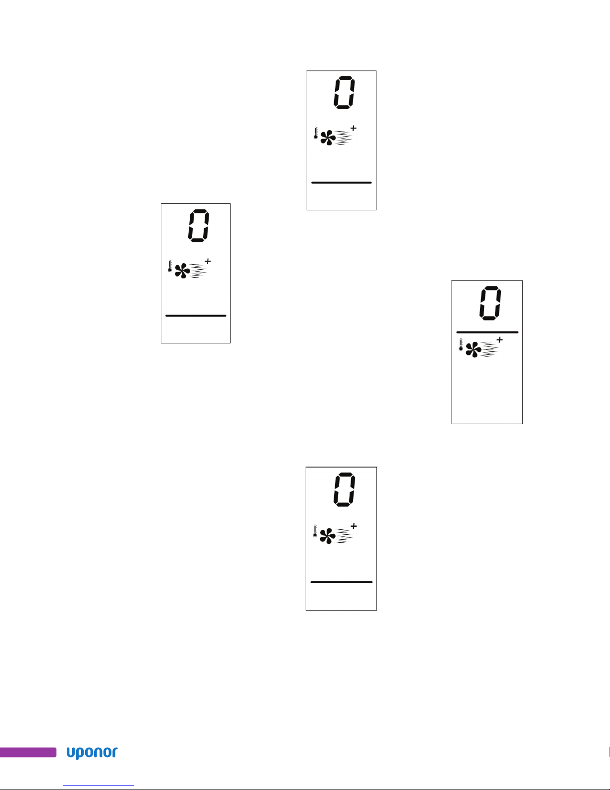
Setting the Radiant
Heating Water
Temperature Channel
To set the Water Temperature Channel
for radiant oor heating, use the
following procedure.
1. Press both the mode and cycle
buttons at the same time.
2. Press cycle three times, and the
radiant heating icon will appear.
The display will look like this:
Figure 3-4
3. Use the + and − buttons to
choose the Water Temperature
Channel that the thermostat
controls (0 indicates no Water
Temperature Channel).
Setting the Zone Pump
for Thermostat Control
To set which zone pump the thermostat
controls, use the following procedure.
1. Press both the mode and cycle
buttons at the same time.
2. Press cycle four times. The
display will look like this.
Figure 3-5
3. Use the + and − buttons to
toggle between the different
zone pumps (0 to 16, with 0
indicating no zone pump).
Setting the Zone Valve
for Thermostat Control
To set which zone valve the thermostat
controls, use the following procedure.
1. Press both the mode and cycle
buttons at the same time.
2. Press cycle ve times. The
display will look like this:
Figure 3-6
3. Use the + and − buttons to
toggle between the different
valves (0 to 16, with 0
indicating no zone valve).
Setting the Air Zone
To set the thermostat’s air zone, use
the following procedure.
1. Press both the mode and cycle
buttons at the same time.
2. Press cycle six times. The
display will look like this:
Figure 3-7
3. Use the + and − buttons to
toggle between the different air
zones (0 to 5, with 0 indicating
no air zone).
Setting the Air Water
Temperature Channel
Air water temperatures are controlled
by selecting the desired air water
channel. There are six optional
channels (0 – 5), with 0 indicating
no air water temperature and 5
indicating the highest temperature.
To set the air water temperature
channel for use with hot-water coils,
use the following procedure.
1. Press both the mode and cycle
buttons at the same time.
2. Press cycle seven times. The
display will look like this:
12
www.uponor-usa.com • www.uponor.ca
Page 13

Figure 3-8
3. Use the + and − buttons to
toggle between the different
air water temperature channels
(0 to 5).
3. Use the + and – buttons to toggle
between the different air water
zone pumps (0 to 16, with 0
indicating no water pump used).
Setting the Air
Water Zone Valve
To set the air water zone valve (a
valve controlling ow to a hydronic
heating system), use the following
procedure.
1. Press both the mode and cycle
buttons at the same time.
2. Press cycle nine times. The
display will look like this:
Figure 3-11
3. Use the + and − buttons to
toggle between the different
dampers (0 to 16, with 0
indicating no damper used).
Setting the Air Water
Zone Pump
To set the air water zone pump
(e.g., a pump for a hydronic heating
system), use the following procedure.
1. Press both the mode and cycle
buttons at the same time.
2. Press cycle eight times. The
display will look like this:
Figure 3-9
Figure 3-10
3. Use the + and − buttons to toggle
between the different air water
zone valves (0 to 16, with 0
indicating no air water valve used).
Setting the Air
Damper Number
To set the air damper number, use
the following procedure.
1. Press both the mode and cycle
buttons at the same time.
2. Press cycle 10 times. The display
will look like this:
Setting the Air
Handler Number
To set the air handler number, use
the following procedure.
1. Press both the mode and cycle
buttons at the same time.
2. Press cycle 11 times. The display
will look like this:
Figure 3-12
Uponor Climate Co˘ntrol™ Network System Thermostat Installation and Operation Guide
3. Use the + and − buttons to
toggle between the different air
handler numbers (0 to 4, with 0
indicating no air handler used).
13
Page 14
Setting the Heat
Recovery Ventilator
(HRV) Number
To set the HRV number, use the
following procedure.
1. Press both the mode and cycle
buttons at the same time.
2. Press cycle 12 times. The
display will look like this:
Figure 3-13
3. Use the + and − buttons to
toggle between the different
HRV numbers (0 to 4, with 0
indicating no HRV used).
Setting the Supplementary
Water Temperature
Channel Number
To set the supplementary Water
Temperature Channel number (e.g.,
for a high-temperature radiator), use
the following procedure.
1. Press both the mode and cycle
buttons at the same time.
2. Press cycle 13 times. The display
will look like this:
Figure 3-14
3. Use the + and − buttons to
toggle between the different
supplementary Water Temperature
Channels (0 to 5, with 0 indicating
no supplementary Water
Temperature Channel).
Setting the Supplementary
Zone Pump
To set the supplementary zone pump
(e.g., a pump for a high-temperature
radiator), use the following procedure.
1. Press both the mode and cycle
buttons at the same time.
2. Press cycle 14 times. The display
will look like this:
Figure 3-15
3. Use the + and − buttons to
toggle between the different
supplementary zone pumps
(0 to 16, with 0 indicating no
supplementary zone pump used).
Setting the Supplementary
Zone Valve
To set the supplementary zone valve
(e.g., a valve controlling ow to a
high-temperature radiator), use the
following procedure.
1. Press both the mode and cycle
buttons at the same time.
2. Press cycle 15 times. The display
will look like this:
Figure 3-16
3. Use the + and − buttons to
toggle between the different
supplementary zone valves
(0 to 16, with 0 indicating no
supplemental zone valve used).
Setting the Auto
Schedule Number
To set the auto schedule number, use
the following procedure.
1. Press both the mode and cycle
buttons at the same time.
2. Press cycle 16 times. The display
will look like this:
14
www.uponor-usa.com • www.uponor.ca
Page 15

Figure 3-17
3. Use the + and − buttons to
toggle between the different
auto schedules (1 to 16).
Setting the
Temperature Offset
To set the temperature offset, use the
following procedure.
1. Press both the mode and cycle
buttons at the same time.
2. Press cycle 17 times. The display
will look like this:
Viewing the Thermostat
Software Revision
To view the thermostat software
revision, use the following procedure.
1. Press both the mode and cycle
buttons at the same time.
2. Press cycle 18 times. The
display will look like this:
Figure 3-19
Figure 3-18
3. Use the + and − buttons to
toggle between the different
temperature offsets (-9.9 to 9.9).
Uponor Climate Co˘ntrol™ Network System Thermostat Installation and Operation Guide
15
Page 16

16
www.uponor-usa.com • www.uponor.ca
Page 17
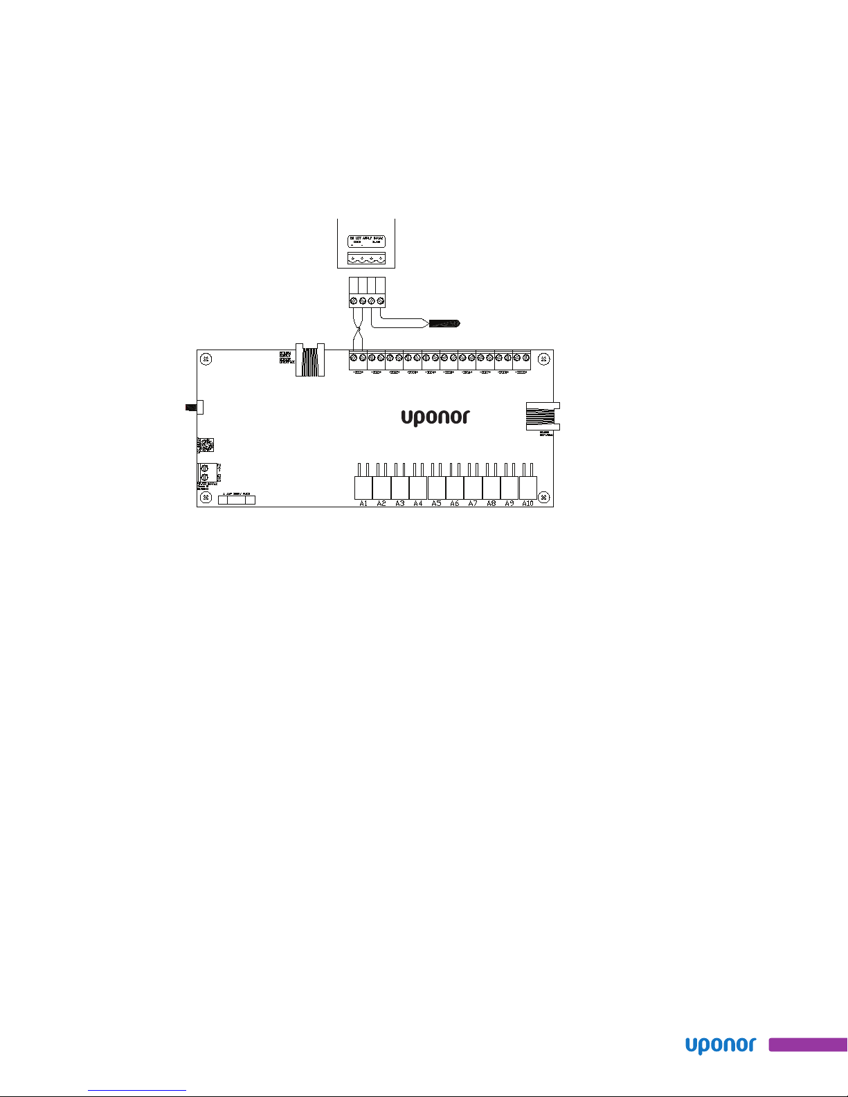
Section 4 –
Plug
Connector
Thermostat
Optional
Slab Sensor
Wiring Diagram
Figure 4-1: Thermostat Wiring Diagram
Uponor Climate Co˘ntrol™ Network System Thermostat Installation and Operation Guide
17
Page 18

Uponor, Inc.
5925 148th Street West
Apple Valley, MN 55124 USA
Tel: (800) 321-4739
Fax: (952) 891-1409
CC-Thermostat_Install Guide_4-08, Copyright © 2008 Uponor, Inc. Printed in the United States
Web: www.uponor-usa.com
Uponor Ltd.
655 Park Street
Regina, SK S4N 5N1 CANADA
Tel: (888) 994-7726
Fax: (800) 638-9517
Web: www.uponor.ca
 Loading...