

Page 1
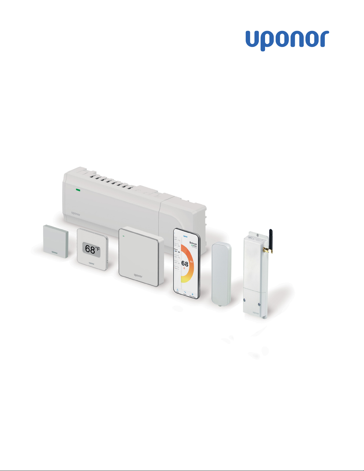
Smatrix Pulse
Installation and Operation Manual
Page 2

Uponor Smatrix Pulse Installation and Operation Manual
is published by
Uponor Inc.
5925 148th Street West
Apple Valley, MN 55124 USA
T 800.321.4739
F 952.891.2008
Uponor Ltd.
6510 Kennedy Road
Mississauga, ON L5T 2X4 CANADA
T 888.594.7726
F 800.638.9517
uponor.com
© 2023 Uponor
All rights reserved.
First edition
First publication March 2023
Printed in the United States of America
Page 3

Table of Contents
Foreword ...................................................................................2
Chapter 1: Copyright and Disclaimer ................................... 3
Compliance .....................................................................................................4
Chapter 2: Safety Instructions ..............................................5
Chapter 3: System Description ............................................. 7
System Overview .......................................................................................... 7
Hardware Overview .................................................................................... 7
Hardware Descriptions .............................................................................8
Chapter 4: System Functionality ......................................... 11
Standard Functionality .............................................................................11
Smart Home Connectivity ......................................................................11
Heating/Cooling Offset .......................................................................... 13
Room Bypass .................................................................................................13
Chapter 5: Hardware Installation ....................................... 15
Installation Procedure ............................................................................. 15
A380265C/A380265A Controllers ................................................... 16
A3801263 Expansion Module (M-262) .......................................... 17
Communication Module (R-208) ................................................... 17
Antenna (A-265) ........................................................................................ 18
A3801263 Relay Module (M-263) ..................................................... 18
Thermostats ................................................................................................... 19
Chapter 6: Wiring ....................................................................21
Controller ......................................................................................................... 21
Output Relays ...............................................................................................22
Relay Module ................................................................................................ 23
Thermostats ..................................................................................................25
Chapter 7: Connecting Wireless Devices .......................... 27
Chapter 8: Clearing Setup Information or Resetting
Devices .....................................................................................31
Chapter 9: System Operation ..............................................33
Chapter 10: Maintenance .....................................................39
Chapter 11: System Connectivity ........................................ 41
Chapter 12: Troubleshooting ................................................43
Chapter 13: Technical Data .................................................. 51
uponor.com l 1
Page 4

Foreword
Uponor is dedicated to partnering with professionals to
create better human environments. As the leading North
American manufacturer of Engel-method crosslinked
polyethylene (PEX-a) piping and provider of PP-RCT
piping solutions, Uponor is dedicated to offering products,
systems, services, support, and solutions to design, install,
and operate high-performing piping systems.
As part of this support, Uponor publishes the Smatrix
Pulse Installation and Operation Manual for contractors,
engineers, architects, building officials, building managers,
and other individuals interested in radiant heating and
cooling as well as HVAC systems.
Uponor has made reasonable efforts to collect, prepare,
and provide quality information and material in this
manual. However, system enhancements may result in
modification of features or specifications without notice.
Note that Uponor is not liable for installation practices
that deviate from this manual or are not acceptable
practices within the mechanical trades, codes, or
standards of practices. If there are differences between
Uponor recommendations and local code, always follow
the more-restrictive criteria. For example, where Uponor’s
recommendations are more restrictive than the local
code, follow the Uponor recommendations to ensure
the product performs as expected and remains covered
under warranty. For warranty information, visit uponor.com
and search "warranty".
It is the installer’s responsibility to ensure the product,
design, and intended installation are acceptable to the
local authority having jurisdiction (AHJ). Please direct any
questions regarding the suitability of an application to
Uponor Technical Services at 888.594.7726 or
Warning!
California Proposition 65 Warning: This product
contains chemicals known to the state of
California to cause cancer and birth defects or
other reproductive harm. For more information,
visit P65Warnings.ca.gov.
2 l Smatrix Pulse | Installation and Operation Manual
Page 5

Chapter 1:
Copyright and Disclaimer
Uponor has prepared this installation and operation
manual and all the content included solely for information
purposes. The contents of the manual (including
graphics, logos, icons, text, and images) are copyrighted
and protected by worldwide copyright laws and treaty
provisions. The user agrees to comply with all copyright
laws worldwide. Modification or use of any of the contents
of the manual for any other purpose is a violation of
Uponor’s copyright, trademark, and other proprietary
rights. The presumption for the manual is that the safety
measures have been fully complied with and, further, that
the Uponor Smatrix Pulse control system, including any
components that are part of such system, covered by the
manual:
• Is selected, planned, and installed and put into operation
by a trained, licensed, and experienced professional
in compliance with current (at the time of installation)
installation instructions provided by Uponor as well as in
compliance with all applicable building and plumbing
codes and other requirements and guidelines.
• Has not been (temporarily or continuously) exposed to
temperatures, pressure and/or voltages that exceed
the limits printed on the products or stated in any
instructions supplied by Uponor.
• Remain in its originally installed location and is not
repaired, replaced, or interfered with, without prior written
consent of Uponor.
• Is connected to potable-water supplies or compatible
plumbing, heating, and/or cooling products approved or
specified by Uponor.
• Is not connected to or used with non-Uponor products,
parts, or components, except for those approved or
specified by Uponor; and
• Does not show evidence of tampering, mishandling,
insufficient maintenance, improper storage, neglect, or
accidental damage before installation and being put
into operation.
While Uponor has made efforts to ensure that the manual
is accurate, Uponor does not guarantee or warrant the
accuracy of the information contained herein. Uponor
reserves the right to modify the specifications and
features described herein or discontinue manufacture of
the Uponor Smatrix Pulse products described at any time
without prior notice or obligation. The manual is provided
“as is” without warranties of any kind, either expressed or
implied. The Information should be independently verified
before using it in any manner.
To the fullest extent permissible, Uponor disclaims all
warranties, expressed or implied, including, but not limited
to, the implied warranties of merchantability, fitness for
particular purpose, and non-infringement.
This disclaimer applies to, but is not limited to, the
accuracy, reliability, or correctness of the manual.
Under no circumstances shall Uponor be liable for any
indirect, special, incidental, or consequential damages
or loss that result from the use of or the inability to use
the materials or information in the manual, or any claim
attributable to errors, omissions, or other inaccuracies
in the manual, even if Uponor has been advised of the
possibility of such damages. Uponor’s total cumulative
liability, if any, will not exceed the amount the user actually
paid for the Uponor Smatrix Pulse wireless control system.
This disclaimer and any provisions in the manual do not
limit any statutory rights of consumers.
uponor.com l 3
Page 6

Compliance
This device complies with Part 15 of the FCC Rules.
Operation is subject to the following two conditions:
1. This device may not cause harmful interference, and
2. This device must accept any interference received,
including interference that may cause undesired
operation.
This device contains license-exempt transmitter(s)/
receiver(s) that comply with Innovation, Science and
Economic Development Canada’s license-exempt RSS(s).
Operation is subject to the following two conditions:
1. This device may not cause interference.
2. This device must accept any interference, including
interference that may cause undesired operation of the
device.
Note: The grantee is not responsible for any changes
or modifications not expressly approved by the party
responsible for compliance. Such modifications could
void the user’s authority to operate the equipment.
Note: This equipment has been tested and found to
comply with the limits for a Class B digital device,
pursuant to Part 15 of the FCC Rules. These limits are
designed to provide reasonable protection against
harmful interference in a residential installation. This
equipment generates, uses, and can radiate radio
frequency energy and, if not installed and used in
accordance with the instructions, may cause harmful
interference to radio communications. However, there
is no guarantee that interference will not occur in a
particular installation. If this equipment does cause
harmful interference to radio or television reception, which
can be determined by turning the equipment off and on,
the user is encouraged to try to correct the interference by
one or more of the following measures:
• Reorient or relocate the receiving antenna.
• Increase the separation between the equipment and
receiver.
• Connect the equipment into an outlet on a circuit
different from that to which the receiver is connected.
• Consult the dealer or an experienced radio/TV technician
for help.
L’émetteur/récepteur exempt de licence contenu dans
le présent appareil est conforme aux CNR d’Innovation,
Sciences et Développement économique Canada
applicables aux appareils radio exempts de licence.
L’exploitation est autorisée aux deux conditions suivantes :
1. L’appareil ne doit pas produire de brouillage;
2. L’appareil doit accepter tout brouillage radioélectrique
subi, même si le brouillage est susceptible d’en
compromettre le fonctionnement.
FCC ID: V9MSM4NA0 and V9MSM4NA1
IC: 7664A-SM4NA0 and 7664A-SM4NA1
4 l Smatrix Pulse | Installation and Operation Manual
Page 7
Chapter 2:
Safety Instructions
This installation and operation manual describes how to
install and properly setup the components of the Uponor
Smatrix Pulse system.
Refer to the following important safety instructions before,
during, and after installation of the Smatrix Pulse system.
Symbols
The following symbols are used in Uponor documentation
to show special precautions when installing and operating
any Uponor equipment.
Warning!
Risk of injury or component damage. Ignoring
warnings can cause personal injury or damage to
system components.
Caution!
Risk of equipment malfunction. Ignoring cautions
can cause system malfunctions.
Note
Important information to the section in the
manual.
Safety Measures
Conform to the following measures when installing and
operating any Uponor equipment.
• Read and follow the instructions in the installation and
operation manual.
• Installation must be performed by a trained, licensed,
and experienced professional in accordance with local
regulations.
• It is prohibited to make changes or modifications not
specified in this manual.
• All power supplies must be switched off before starting
any wiring work.
• Do not use water to clean Uponor components.
• Do not expose the Uponor components to flammable
vapors or gases.
Power
Warning!
The Uponor system uses 115V 60 Hz AC power. In
case of emergency, immediately disconnect the
power.
Technical Constraints
Caution!
To avoid interference, keep installation/data
cables away from power cables of more than 50V.
Limitations for Radio Transmissions
Wireless Uponor products use radio transmission for
communication. The frequency used is reserved for similar
applications, and the chances of interference from other
radio sources are very low.
However, in some rare cases, it might not be possible to
establish perfect radio communication. The transmission
range is sufficient for most applications, but each
building has different construction that may affect radio
communication and maximum transmission distance.
If communication difficulties exist, Uponor recommends
relocating the antenna to a more optimal position and
installing Uponor radio sources at least 16" (41 cm) apart
for solving communication problems.
Disposal
At the end of its working life, do not dispose of any Smatrix
Pulse components with other household waste. To prevent
possible harm to the environment or human health
from uncontrolled waste disposal, please separate this
from other types of wastes and recycle it responsibly to
promote the sustainable reuse of material resources. For
proper disposal information, contact local recyclers for
environmentally safe recycling.
Uponor cannot accept any responsibility for damage
or breakdown that can result from ignoring these
instructions.
uponor.com l 5
Page 8
Chapter 3:
System Description
Smatrix Pulse is a wireless zoning control system designed
for radiant heating and cooling installations with the
ability to integrate forced-air heating and cooling.
System Overview
The Smatrix Pulse hardware consists of one or multiple
controllers, an optional Communication Module,
thermostats, actuators, and wireless relays. The Controller
manages the operation of the actuators when the
thermostats detect a demand for heating and/or cooling.
System optimization and settings (for up to four
controllers) is completed through the Smatrix Pulse App
(connected via the Communication Module). The system
can function without the Communication Module but will
reduce the level of system functionality.
Different models of thermostats control heating and
cooling operation. Designed for maximum comfort, the
thermostats communicate with the controller by radio
link. It is possible to mix the different types of Smatrix Pulse
thermostats in the same installation.
Wireless relays provide installation flexibility when needing
to control other heating and cooling devices when running
additional wiring is a challenge.
Hardware Overview
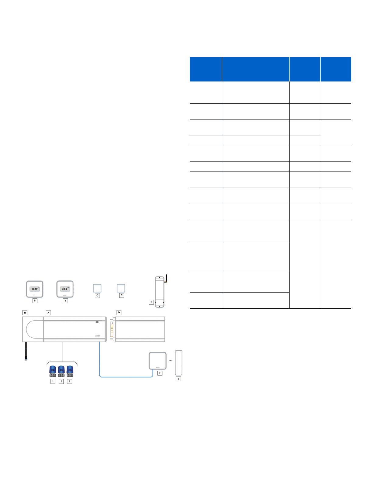
The figure below shows the hardware available for the
Uponor Smatrix Pulse system.
Part
Number
A380265C
A380265A
A3800169
A3800161 Mini Sensor (T-161) C
A3801262
A3801263 Relay Module (M-263) E 16*
A3801208
A3801265
A3850050
A3030522
A3030523
A3030524
A3023522
Description Reference
Controller (X-265) with
Communication Module
(R-208)
Controller (X-265) with
Antenna (A-265)
Digital Thermostat
(T-169)
Expansion Module
(M-262)
Communication Module,
replacement part
Antenna, replacement
part
Transformer,
replacement part
Two-wire Thermal
Actuator for Uponor
EP Heating Manifolds
Two-wire Thermal
Actuator for Uponor
TruFLOW™ Classic and
Jr. Valved Manifolds
Two-wire Thermal
Actuator for Uponor
Stainless-steel Manifolds
Thermal Actuator,
four-wire
A, F, H 1
A, G, H 3
B
D 4
F N/A
G N/A
H N/A
I 56
Maximum
per
System
48
Figure 3-1: Smatrix Pulse hardware
Table 3-1: Smatrix Pulse hardware
*Limit of four (4) A3801263 Relay Modules (M-263) per Controller
uponor.com l 7
Page 9

Hardware Descriptions
A3800169 Digital Thermostat
(T-169)
The Digital Thermostat shows the
current room temperature, set
temperature, or relative humidity on
the display. Temperature settings are
Figure 3-2:
A3800169 Digital
Thermostat
(T-169)
Main Features
• Power saving e-paper display (updates every 10
minutes)
• Displays Fahrenheit or Celsius
• Operative sensor for increased comfort
• Calibration of displayed room temperature
• Heating/cooling demand as well as low battery
indication on display
• Displays Uponor logo and software version during power
up sequence
• Setpoint range is 41 – 95°F (5 – 35°C); maximum and
minimum setting may be limited by system settings
• Enhanced room temperature control with use of optional
floor sensor
• Displays optional temperature sensor values if sensors
are connected and relevant functionality is activated
• Switch between Comfort and ECO mode with scheduling
(requires Smatrix Pulse App)
• Adjust ECO setback value
• Relative humidity limit alarm indicated in display
(requires Communication Module)
• Invert display color
• Communication distances up to 98 ft. (30 m) away from
the controller
adjusted using the buttons on the
side of the thermostat.
A3800161 Mini Sensor (T-161)
The Mini Sensor is a small, simple
thermostat with no display or
buttons. Use this in rooms for discreet
temperature monitoring without
the need for local temperature
adjustment.
Figure 3-3:
A3800161 Mini
Sensor (T-161)
Main Features
• Operative sensor for increased comfort
• Adjust setpoint temperature via the Smatrix Pulse App
(requires Communication Module)
• Setpoint range is 41 – 95°F (5 – 35°C); maximum and
minimum setting may be limited by system settings
• Optional floor temperature sensor (connected to the
thermostat); floor temperature settings (maximum/
minimum) only available using the Smatrix Pulse App
(requires Communication Module); otherwise, uses
system defaults
• Relative humidity limit indicated in Smatrix Pulse App
(requires Communication Module)
• Communication distances up to 98 ft. (30 m) away from
the controller
Included Components
• Mini Sensor (T-161)
• Wall bracket
• Adhesive tape
• Battery (CR2023 3V)
• Mounting hardware (for wall bracket)
Included Components
• Digital Thermostat (T-169)
• Wall bracket
• Adhesive tape
• Battery (CR2023 3V)
• Mounting hardware (for wall bracket)
8 l Smatrix Pulse | Installation and Operation Manual
Page 10
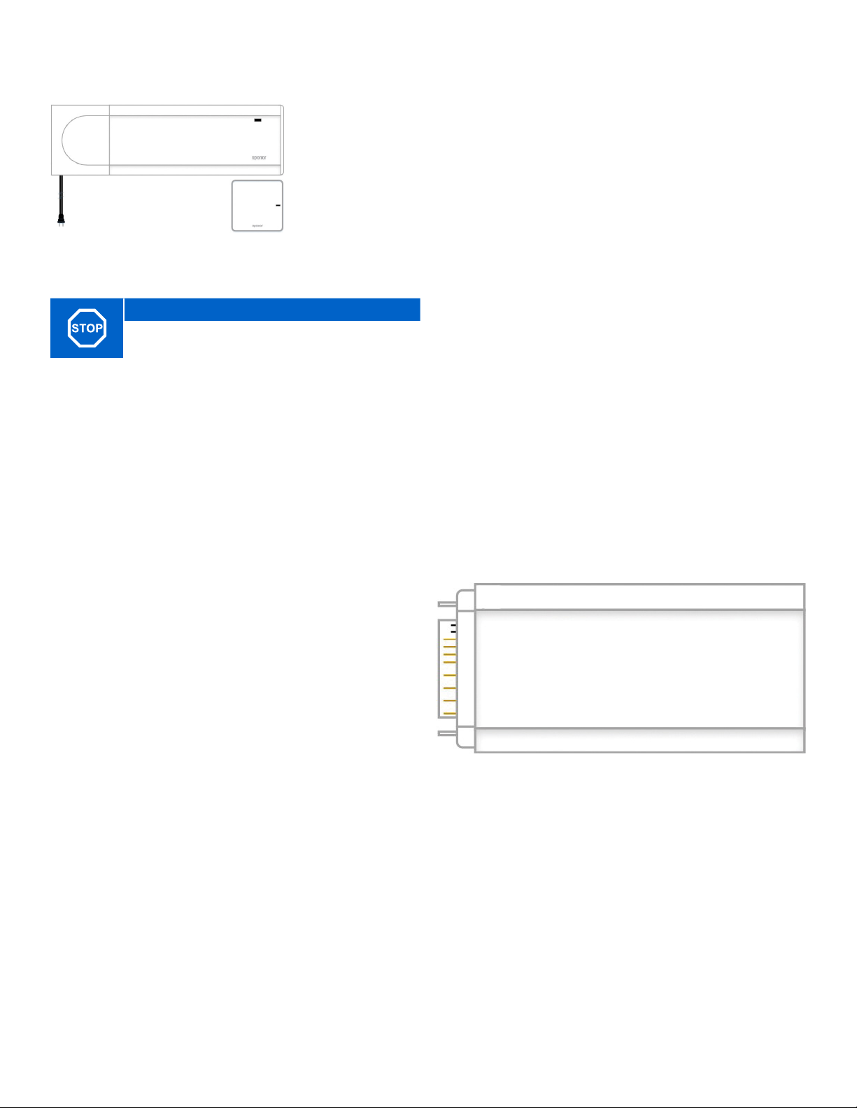
A380265C Controller (X-265) with
Communication Module (R-208)
Figure 3-4: A380265C Controller
(X-265) with Communication
Module (R-208)
Warning!
Per Table 3-1, use Uponor 24V actuators to ensure
compatibility with the controller.
The Controller operates the actuators, which, in turn,
affect the flow of the supply water to change the
indoor temperature using information transmitted from
registered thermostats and system parameters.
The Controller, which is typically located near the system
manifolds, can operate up to six (6) thermostats and eight
(8) actuators.
Main Features
• Integrated Dynamic Energy Management functions
• Autobalancing (default)
• Comfort setting, room bypass, supply temperature
monitoring (requires Smatrix Pulse App and
Communication Module)
• Electronic control of 24V actuators
• Connects up to eight (8) actuators
• Two-way communication with up to six (6) thermostats
• Heating/cooling outputs, and/or Comfort/ECO mode
switched by dry contact or Smatrix Pulse App (requires
Communication Module)
• Separate relays for control of pump and boiler (other
control functionality available via Smatrix Pulse App)
• Valve and pump exercise
• Relative humidity control (requires Smatrix Pulse App)
• Control of combined underfloor heating/cooling and
ceiling cooling or fan coils (requires Smatrix Pulse App)
• Lower indoor temperature in heating mode or increase
indoor temperature in cooling mode with ECO mode; ECO
mode activates in all rooms at once using a dry contact
or Smatrix Pulse App (requires Communication Module)
• 115V plug-in power cord (42")
Options
• App connectivity via Communication Module (remote
connection requires connection to Uponor Cloud services)
• Increase controller functionality by adding an Expansion
Module for up to six (6) additional thermostats and up to
six (6) additional actuators
• Connect up to four controllers into one system
(requires Smatrix Pulse App)
• Modular placement (detachable Transformer)
• Free placement and orientation when installing Controller
(except Communication Module)
Included Components
• A380265C Controller (X-265) with Communication
Module (R-208)
• Power supply/Transformer (part number A3850050)
• DIN rail
• Mounting hardware
• End cap
A3801262 Expansion Module (M-262)
The Expansion Module will increase the Controller
capacity with six (6) additional thermostats along with
six (6) more actuators. The Expansion Module operates
the actuators, which, in turn, affect the flow of the
supply water to change the indoor temperature using
information transmitted from registered thermostats and
system parameters.
Figure 3-5: A3801262 Expansion Module (M-262)
Main Features
• Electronic control of 24V actuators
• Connects up to six (6) additional actuators
• Two-way communication with up to six (6) additional
thermostats
• Plug-in connection with the Controller
• No additional power wiring needed
Included Components
• A3801262 Expansion Module (M-262)
uponor.com l 9
Page 11
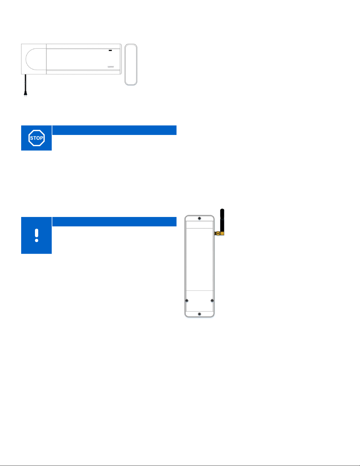
A380265A Controller (X-265)
with Antenna (A-265)
Figure 3-6: A380265A Controller
(X-265) with Antenna (A-265)
Warning!
Per Table 3-1, use Uponor 24V actuators to ensure
compatibility with the Controller.
The Controller operates the actuators, which, in turn,
affect the flow of the supply water to change the
indoor temperature using information transmitted from
registered thermostats and system parameters.
The Controller, which is typically located near the system
manifolds, operates up to six (6) thermostats and eight
(8) actuators.
Note
If using remote access to view and adjust
room temperatures along with other smart
home settings, the system must include one
Communication Module.
Main Features
• Integrated Dynamic Energy Management functions, such
as autobalancing (on by default)
• Electronic control of 24V actuators
• Connects up to eight (8) actuators
• Two-way communication with up to six (6) thermostats
• Heating outputs for Boiler and Pump operation
• General purpose input (GPI) for heating/cooling switch
over
• Valve and pump exercise
• Control of combined underfloor heating and cooling
• ECO mode provides lower indoor temperature in heating
mode and increased indoor temperature in cooling
mode; activated in all rooms at once using a dry contact
• Communication distances up to 98 ft. (30 m) away from
the controller when used as a sub-Controller
• 115V plug-in power cord (42")
Options
• Increase Controller functionality by adding an Expansion
Module that adds six (6) additional thermostats and six
(6) additional actuators
• Other functions such as comfort setting, room bypass,
and supply temperature monitoring requires (requires
Communication Module and Smatrix Pulse App)
• Modular placement (detachable Transformer)
• Free placement and orientation when installing the
controller (except the antenna; must be mounted
vertical)
• Heating/cooling outputs, and/or Comfort/ECO mode
switched by dry contact or Smatrix Pulse App (requires
Communication Module)
Included Components
• Controller with Antenna (part number A380265A)
• Power supply/Transformer (part number A3850050)
• DIN rail
• Mounting hardware
• End cap
A3801263 Relay Module (M-263)
The Relay Module adds two extra
output relays to the system.
These can be setup in different
combinations to control heating and
cooling operation.
The Relay Module can also be paired
with a thermostat to control a fan
coil or furnace and air-conditioning
combination, along with fan
operation. This application uses three
(3) relays.
Main Features
• Dry contacts (24 VAC, 5 A)
• Pump control and heating/cooling
Figure 3-7:
A3801263 Relay
Module (M-263)
output function
• Other combinations are available,
but require Communication Module
and Smatrix Pulse App
• Communication distances up to
98 ft. (30 m) away from Controller
10 l Smatrix Pulse | Installation and Operation Manual
Page 12
Chapter 4:
System Functionality
The Smatrix Pulse system provides a wide variety of
functionality and options to enhance the comfort and
operation for residential radiant heating and cooling
systems. Some of these features can only be accessed
or enabled with the installation of the Communication
Module.
Standard Functionality
Feature
Actuator Management
Autobalancing
Cloud Service
Comfort and Economy Mode
Cooling Operation
Cooling Options
Cooling – Second Stage
Forced Air/Fan Coils
Heating Cooling Offset
Heating Safeguard
Pump Management
Relative Humidity (RH) Control
Room Bypass
Room Bypass Time limit
System Clock
Table 4-1: Standard Functionality and Smart Home
Connectivity Features
Standard
Functionality
P P
P P
P P
P P
Actuator Management
Actuator management prevents too many actuators from
being open at the same time. This reduces the peak power
needs. Reduce peak current by delaying the opening of
some actuators (as they use most current while being
opened). Up to eight (8) actuators can be opened at the
same time. Additional actuators are queued and opened
in order.
Autobalancing
The Uponor Smatrix controller can operate the actuator
outputs by either on/off signals or by Autobalancing (on
by default), using pulse width modulation (PWM) signals.
Smart
Home
P
P
P
P
P
P
P
P
P
P
P
Autobalancing is a function where the system calculates
the actual energy need of single rooms or zones and
adapts the output power of each loop to its length. This
means a short loop might get 20% on time while a long
loop might get about 60%. The autobalancing continues
through the seasons and throughout the changing
conditions and usage patterns of the household, removing
the need for manual balancing. This gives more even floor
temperatures and faster system reaction times with lower
energy consumption than standard control systems.
Note
Default for Autobalancing is set to On. Setting this
value to Off requires the Communication Module.
Note
Autobalancing can be used in combination with
hydronic balancing.
Smart Home Connectivity
Note
Smart home connectivity requires the use of the
Communication Module (R-208) and the Uponor
Smatrix Pulse App.
Cloud Services
Use the Communication Module to connect to the
Uponor Cloud to access system information and settings,
including:
• Viewing and adjusting room temperatures
• Setting Home or Away status
• Changing mode of operation (heating/cooling)
• Viewing alarms
• Viewing weather forecast
• Viewing room temperature data (trends)
• Setting up Comfort/ECO profiles and assigning to rooms
• Setting low temperature limits (average)
Comfort and Economy (ECO) Modes
Using the Communication Module and Smatrix Pulse
App, it is possible to change the temperature setpoints
between two different temperatures. The available modes
are Comfort and ECO (economy). Use the Smatrix Pulse
App to switch between Comfort and ECO modes and also
create a schedule and apply it to one or multiple zones.
uponor.com l 11
Page 13
0:00 6:00 24:0018:0012:00
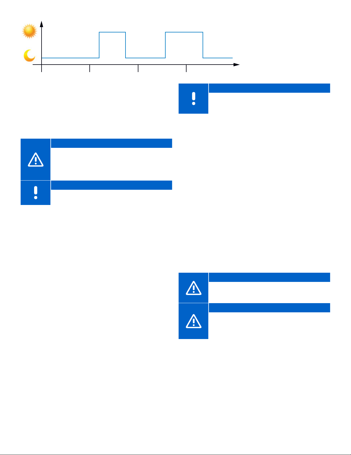
Figure 4-1: Comfort and ECO mode examples
Figure 4-1 shows the system delivers heating in Comfort
mode in the morning and late afternoon but enters
ECO mode at night and in the middle of the day when
the house is normally unoccupied and energy can be
conserved.
Caution!
Connecting an external Comfort/ECO switch to
the GPI terminals on the Controller will override the
time schedules in the Smatrix Pulse App when the
switch is closed. This feature will require setup in
the app.
Note
Use only one Comfort/ECO switch in the system.
Cooling Operation
The controller can operate underfloor cooling installation
based on customer needs. Adjust temperatures with
thermostats or by using the Smatrix Pulse App.
As soon as the temperature measured at a thermostat is
higher than the setpoint temperature, a demand to cool
the room or zone is created and sent to the Controller. The
Controller will open the actuators or turn on the cooling
terminals on the relay according to the current operating
mode and settings. Once the set temperature is reached,
the actuators will close, or the air cooling will turn off.
Cooling Options
Use the Smatrix Pulse App to set up the following two
cooling methods.
• Underfloor cooling (delivered via hydronic loops in the
floor)
• Air cooling (delivered via conventional air conditioning or
fan coil units connected to a relay module registered to a
room thermostat)
Note
If selecting air cooling as the primary method to
cool the room or zone, it is important to turn off the
Autobalancing feature.
Cooling – Second Stage
The Smatrix Pulse system can control a second stage of
cooling. In rooms where underfloor cooling is installed and
a fan coil is also available, underfloor cooling is started
when the room temperature rises above setpoint (first
stage), and the fan-coil cooling is started or activated
depending on how fast the room temperature is
increasing. Second-stage cooling will end once the room
temperature is at or below the set temperature.
The relay must be registered to a thermostat directly for
operation of air-system control. See page 28 for additional
information about registering the thermostat to a relay.
Forced Air/Fan Coils
Use the Relay Module (M-263) (part number A3801263)
to control air heating and cooling. The air heating and
cooling equipment is wired to a relay module and
registered (linked) to a thermostat. The operation is
dependent on the settings in the Smatrix Pulse App.
Caution!
Limit of four (4) Relay Modules for forced air
systems/fan coils per Controller to ensure system
performance.
Caution!
When connecting a Relay Module to control air
heating or cooling, make sure an actuator is not
connected to the first channel the thermostat is
assigned to.
12 l Smatrix Pulse | Installation and Operation Manual
Page 14

Heating/Cooling Offset
Uponor uses an offset temperature to adjust the setpoints
when switching between heating and cooling. This
improves the performance of the system and reduces the
need for manual setpoint adjustments when switching
between heating and cooling. The offset is 4°F (2°C) and is
used to increase the setpoints when switching to cooling.
When switching back to heating, the value is used to
reduce the setpoint.
Heating Protection
If the connection to one thermostat or multiple
thermostats is lost (i.e., no longer communicating to a
Controller), the Controller activates a safety feature for
the affected loop(s) and the actuators are run with a
set interval to deliver heating to the room or zone. This
function deactivates when the thermostat(s) reconnect
or unregister from the Controller.
Pump Management
Each controller includes a pump relay to connect
a circulation pump. Default operating mode of the
circulation pump is set to Individual mode. Use the
Smatrix Pulse App (requires Communication Module) to
change the setting, if needed. Available settings are Not
Configured, Common and Individual.
• Common mode: Relay function is set on a system-wide
basis. One circulation pump per system is connected to
the Primary Controller only or Controller that is connected
to the Communication Module. When there is a demand
anywhere in the system, the pump wired to the Primary
Controller is started.
• Individual mode: Relay function is set on a Controller
basis. One circulation pump per Controller is connected.
When there is a demand to a specific Controller, only the
pump connected to that controller is started.
• Relay module (optional): When using the relay module
to control a pump, the mode of the pump control is set
through in the Smatrix Pulse App.
Relative Humidity/Condensation Control
To avoid condensation when operating underfloor cooling,
Uponor recommends measuring the relative humidity (RH)
in the rooms. The relative humidity is measured with one
or more thermostats.
Cooling is shut off on a per-room or zone basis when the
RH limit is reached (set in the Smatrix Pulse App, default
75%). If a dehumidifier is installed, one per controller, it will
be activated when the dehumidifier start limit is reached.
Cooling will start again, and the dehumidifier is
deactivated when the relative humidity falls below a
hysteresis set in the Smatrix Pulse App (“dead zone”,
default 5%) and has run for a minimum of 30 minutes.
Room Bypass
The system can use up to two rooms (per controller), when
in heating mode, as bypass to maintain minimum flow in
the system. Rooms can be selected manually or by using
the Room Bypass Time Limit function.
Room Bypass Time Limit
The Room Bypass Time Limit function prevents run times
shorter than 30 minutes in the system. It does this by
analyzing system data (if a room is close to a demand,
setpoints, room temperatures, etc.) and chooses suitable
rooms to use as bypass.
System Clock
To facilitate accurate log data, scheduling and different
timer settings, the Controller receives the correct time and
date from Uponor Cloud services. The clock can be set to
automatically switch between summer and winter time.
Caution!
Changing operation of the pump control (and/or
cooling allowed) in the Smatrix Pulse App will set
all relays to Not Configured, and they will need to
be reconfigured.
Note
In systems with multiple Controllers (Primary/
sub-configuration), all relays are initially set to
Not Configured and require configuration during
the installation.
uponor.com l 13
Page 15
Chapter 5:
Hardware Installation
Installation Procedure
Uponor recommends the following steps to provide the
best possible installation results:
• Prepare for Installation (see page 15)
• Install Controller(s) (see page 16)
• Install Communication Module or Antenna
(see pages 17-18)
• Install the Relay Module (see page 18)
• Install Thermostats (see page 19)
After installing the hardware, Chapter 6: Wiring will
describe how to wire the system components, connect
the wireless devices, and finalize setup using the Smatrix
Pulse App.
Prepare for Installation
• Verify the contents of the package with the packing list.
• Check whether an external temperature sensor (e.g., floor
sensor) is to be installed with a thermostat.
• Review the wiring diagram in the manual or inside the
Controller cover.
• Ensure the Controller can be installed near the manifold.
Note that each manifold should have its own controller
(unless the manifold is a single zone).
• Ensure all Smatrix Pulse components are protected from
exposure to water.
Required Tools
Refer to the following list of tools required to install the
Smatrix Pulse hardware:
• Wire cutters
• Small Phillips screwdriver
• Flathead screwdriver
• T-10 bit (wiring compartment on the controller)
• Level
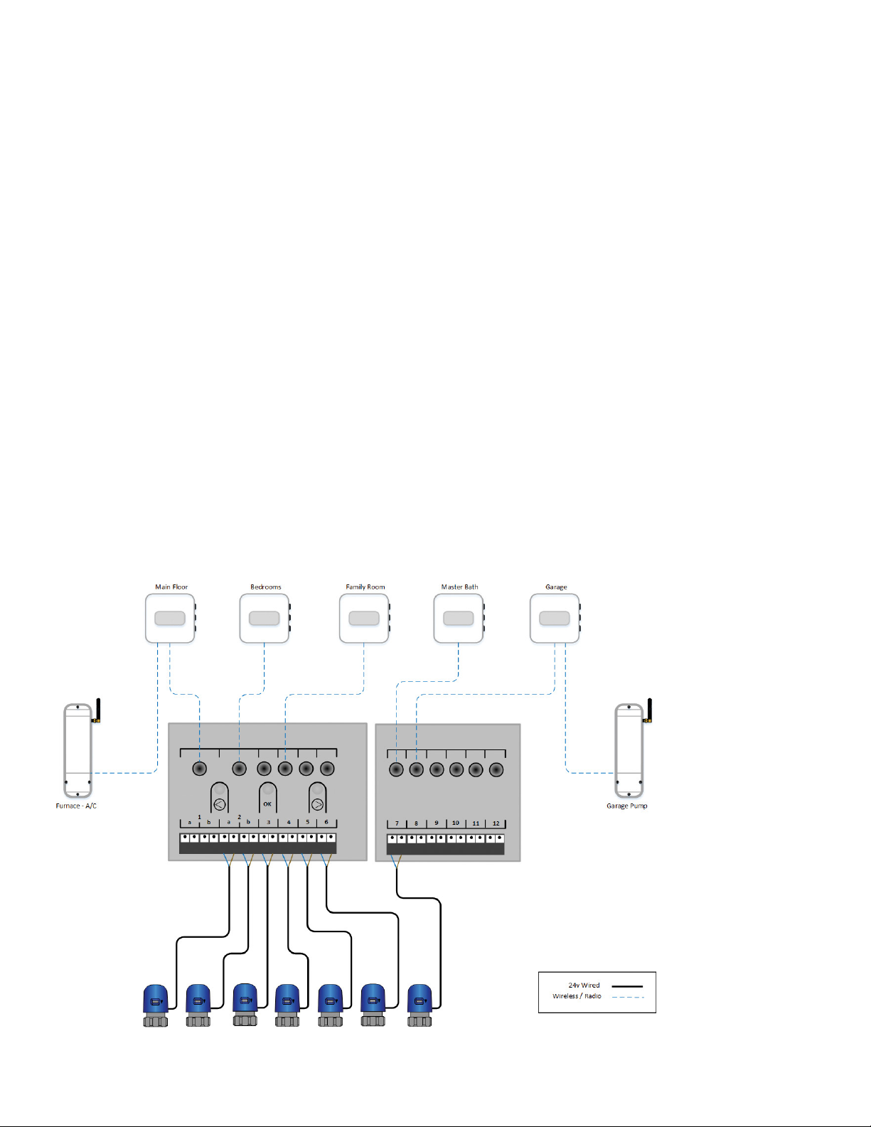
Installation Example
Figure 5-1: Installation example
uponor.com l 15
Page 16
Installation Overview
• The example system has five (5) heating zones and one
(1) cooling zone (Main Floor).
• The Main Floor is registered to Channel 1 but has no
actuator(s). This is due to the system controlling forcedair heating and cooling but no radiant. In instances like
this, the thermostat needs to be assigned to a channel
(in this case, 1) and registered to the relay.
• Bedrooms thermostat is assigned to Channels 2 and 3
and will control actuators connected to 2A, 2B, and 3.
• Family Room heating will open actuators connected to 4
through 6.
• Master Bath heating will open actuators connected to 7.
• Garage thermostat is assigned to Channel 8, but no
actuator is connected. The Garage thermostat is also
linked to a relay module to operate a zone pump on a
call for heating.
Caution!
All thermostats need to be registered to a
controller for it to appear in the app
Hardware Handling
• The Primary Controller is the device that is connected to
the Communication Module. All others are sub-Controllers.
• A system does not require a Primary Controller, however,
system functionality will be limited.
• Sub-Controllers can only be registered to the Primary
Controller.
• Relay modules can be registered to both Primary and
sub-Controllers.
• The Digital Thermostat (T-169) (part number A3800169) is
the only thermostat that can connect to a Relay Module.
• A thermostat can only be linked to one Controller.
• The Controller will time out after 10 minutes of inactivity
and revert to normal operation. The timer is reset when a
button has been pressed.
• If programmed schedules exist, individual rooms may
operate without following a schedule.
• Setting up a system for remote access and connectivity
will require a mobile device (e.g., smartphone, tablet,
etc.).
A380265C/A380265A Controllers
Controllers are designed for modular installation, meaning
the individual parts (Transformer, Controller, Expansion
Module, and end cap) easily snap together. However,
should the installation require it, the power supply, or
Transformer (part number A3850050), can be mounted
separately.
Caution!
The Transformer is heavy and might detach if the
Controller is held in a vertical position (or upside
down) without the cover on.
Caution!
The Expansion Module must be attached by
snapping it into place due to connection pins used
for connecting to the Controller.
Note
Wires between the Transformer and the Controller
must be disconnected prior to detaching the
Transformer.
The components can snap on or off without needing to
remove the covers or by sliding them into place when the
covers are removed.
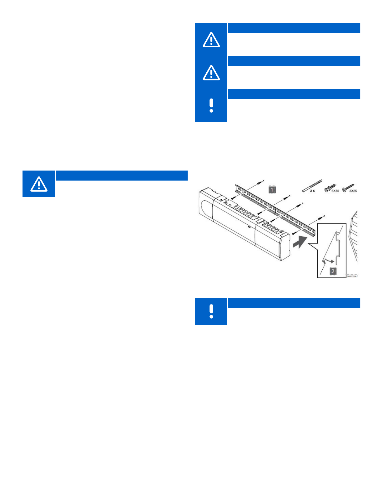
Figure 5-2: Mounting the Controller
Note
Only one Expansion Module is supported per
controller.
Mounting the Controller
• Find a suitable location in proximity to the manifold and
115V power supply/outlet.
• Remove the DIN rail from the package and place on the
wall and level. Note that the DIN rail included will support
both the Controller and the Transformer.
• Mark a minimum of two locations per DIN rail for screw or
anchor locations.
• Install the DIN rail onto the wall surface using the
necessary hardware.
• Assemble or connect all components prior to installing
on to the DIN rail.
• Snap the assembled hardware onto the DIN rail.
16 l Smatrix Pulse | Installation and Operation Manual
Page 17
Removing the Controller from the DIN Rail
• Looking at the bottom of the controller, locate two black
tabs with holes in the center.
• Using a flathead screwdriver, insert the bit into the hole
and apply gentle pressure against the case to extend
the tab.
• Angle the Controller away from the wall.
• Remove the Controller from the DIN rail.
A3801262 Expansion Module (M-262)
Mounting the Expansion Module
• Remove the DIN rail from the package and place at the
end of the rail for the Controller and level.
• Mark a minimum of two locations per DIN rail for screw or
anchor locations.
• Install the DIN rail onto the wall surface using the
necessary hardware.
• Connect the Expansion Module to the Controller and
install on the DIN rail.
• Snap the assembled hardware onto the DIN rail.
Separating the Expansion Module from
the Controller
• Insert a flathead screwdriver in the seam (or slot)
between the Controller and Expansion Module towards
the top.
• Twist the screwdriver until the “snap lock” releases.
• Repeat the same previous steps towards the bottom of
the seam.
• Remove the Expansion Module. Use caution not to
damage or bend the connector pins.
Removing the Expansion Module from the
DIN Rail
• Use the step above to separate the Expansion Module
from the Controller
• Looking at the bottom of the Expansion Module, locate
the black tab with a hole in the center.
• Using a flathead screwdriver, insert the bit into the hole
and apply gentle pressure against the case to extend the
tab.
• Angle the Expansion Module away from the wall.
• Remove the Expansion Module from the DIN rail.
Communication Module (R-208)
The Communication Module contains both an antenna for
internal connections to thermostats and sub-controller
and a local network (LAN) module for Wi-Fi or Ethernet
communication.
Mounting the Communication Module
Caution!
Do not install a Communication Module inside a
manifold cabinet.
Caution!
Install the Communication Module vertically to
ensure the best communication.
• Remove from the packaging and separate the
Communication Module from its removable back mount.
• Attach the back mount to the wall using the hardware
included in the packaging.
• The back can be attached to the wall using adhesive
tape, screws, wall anchors, or DIN rail.
• If using DIN rail, use the extra back mount included in the
packaging with the black tab.
• Connect the Communication Module to the Controller
prior to reinstalling into the back mount.
Note
Only one Communication Module is needed per
system..
Connecting the Communication Module
The communication
cable and optional
Ethernet cable is
routed differently to
the Communication
Module, depending on
which back mount is
being used.
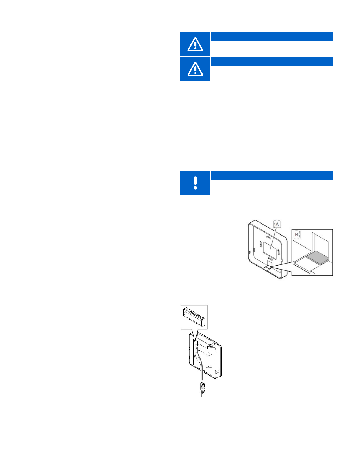
Figure 5-3: Breakout tab
Option 1: Standard Back-Mount Case
• Remove the breakout tab (B) on the
bottom of case (A).
• Attach the back mount to the wall
using the hardware (included).
• Insert the Ethernet cable through
the opening and connect to the
Communication Module.
• There are two connections on the
back of the Communication Module.
Connect to the port showing the
picture of the Controller.
• Install the Communication Module into
the back mount.
Figure 5-4: Route
Ethernet cable
uponor.com l 17
Page 18
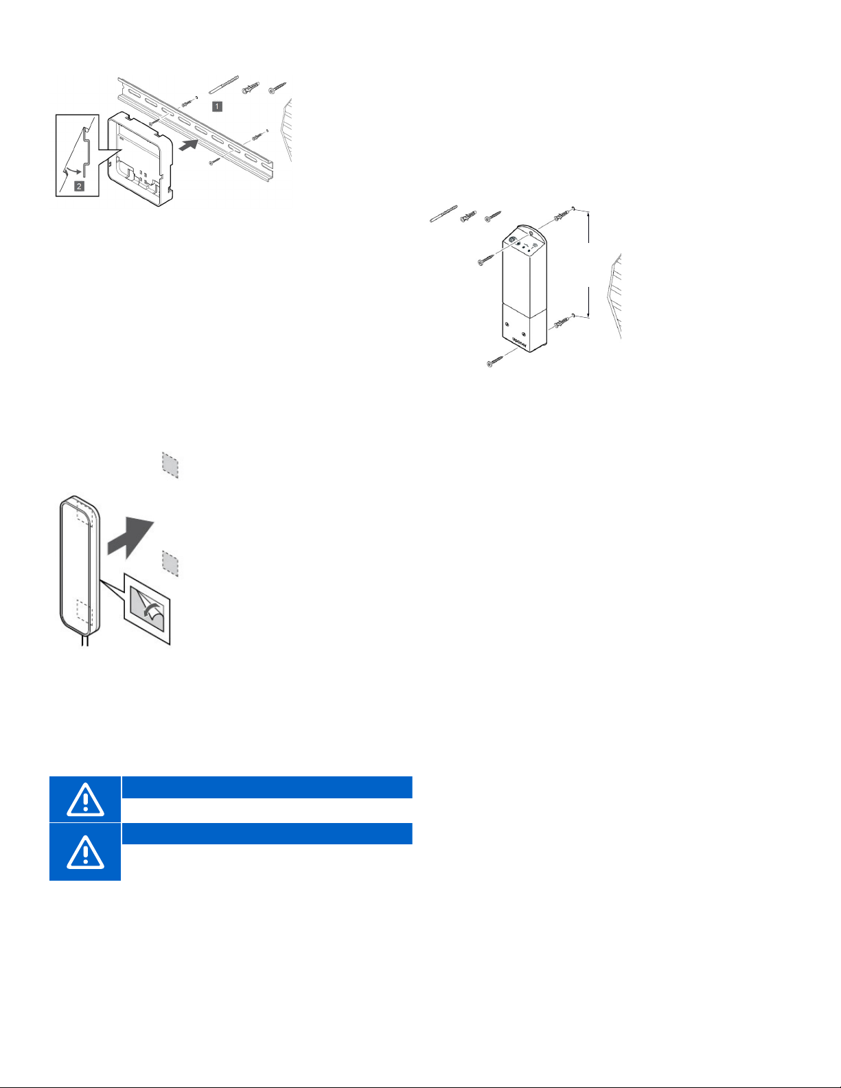
Option 2: DIN Rail Back-Mount Case
• Attach the
DIN rail to the
wall using the
appropriate
hardware.
• Snap the back
mount onto the
DIN rail.
Figure 5-5: Attaching case to DIN rail
• Route the Ethernet cable through the left opening on the
bottom of the case and connect to the Communication
Module
• There are two connections on the back of the
Communication Module. Connect to the port showing
the picture of the Controller.
• Install the Communication Module into the back mount.
• A click should be audible with a completed connection.
• Apply gentle pressure pulling down on the Ethernet cable
to ensure the connection is secure.
Antenna (A-265)
The Antenna is packaged with
a Controller in part number
A380265A. The Smatrix Pulse
system can be installed
with antennas only and no
Communication Module, so be
aware that system functionality
will be limited (see Chapter 4:
System Functionality). When
installing a system solely with
antennas, each Controller will
Figure 5-6: Antenna
installation
Caution!
Install the Antenna outside a manifold cabinet.
Caution!
Install the Antenna vertically to ensure the best
communication.
operate independently. When
installing and linking a Controller
in a system with a Controller that
is connected to a Communication
Module (primary), additional
Controllers with Antennas become
sub-Controllers.
Connecting the Antenna
• Route the Ethernet cable attached to the Antenna and
plug it into the connection on the bottom right hand of
the Controller.
• A click should be audible with a completed connection.
• Apply gentle pressure pulling down on the Ethernet cable
to ensure the connection is secure.
A3801263 Relay
Module (M-263)
Using a Relay Module
6.375" (162 mm)
Figure 5-7: Relay
Module installation
Different functionality combinations are available when
using the Relay Module. To access these requires the
Communication Module.
Placing the Relay Module
Use the following recommendations when determining the
location of the Relay Module:
• Locate the Relay Module close to the device it will control.
• Place the Relay Module above the device(s) to avoid
potential water damage.
• Ensure the Relay Module is protected from exposure to
water.
• Check to make sure the cover can be easily removed
(there is proper clearance) and the terminals are easily
accessible.
Mounting the Relay Module
• Attach the Relay Module to the wall or surface.
• Use suitable hardware included in the packaging to
secure the Relay Module to the determined locations.
helps integrate other
systems (forced air/
fan coils, etc.), simplifies
or reduces wiring
complexity, and provides
a solution where it is
difficult to run wires to
activate heating (and
cooling) equipment.
Mounting the Antenna
• Attach the Antenna to the wall using the adhesive strips
included in the packaging.
18 l Smatrix Pulse | Installation and Operation Manual
Page 19
Thermostats
V1.0
Smatrix Pulse thermostats provide information that is
transmitted via wireless signal to Controllers and/or Relay
Modules. This information is used to determine whether
heating or cooling is needed for the individual zones and
operate the appropriate devices.
Use the following instructions for both the Digital
Thermostat (T-169) (part number A3800169) and the Mini
Sensor (T-161) (part number A3800161).
Placing the Thermostats
• Make sure the thermostat is placed within the room or
area(s) it will control.
• Select an indoor wall and a position 5 ft. (1.5 m) above
the floor or at eye level.
• Ensure the thermostat is away from direct sunlight and
unaffected by solar gain.
• Ensure the thermostat is away from any source of heat
(television set, electronic equipment, fireplace, spotlights,
etc.).
• Ensure the thermostat is away from any sources of water
or excessive humidity.
• Ensure the thermostat is positioned at least 16" (40 cm)
away from the Controller to avoid interference.
Labeling the Thermostats
Due to the nature of a completely wireless thermostat, it is
easy for thermostats to get placed in the wrong room or
zone. Uponor recommends labeling the thermostat during
installation to alleviate any confusion. If installing multiple
Controllers, include a number reference or location for the
specific Controller. This will help once it is time to begin
the registration process of linking the thermostats to the
correct devices.
Figure 5-8: Breakout tab
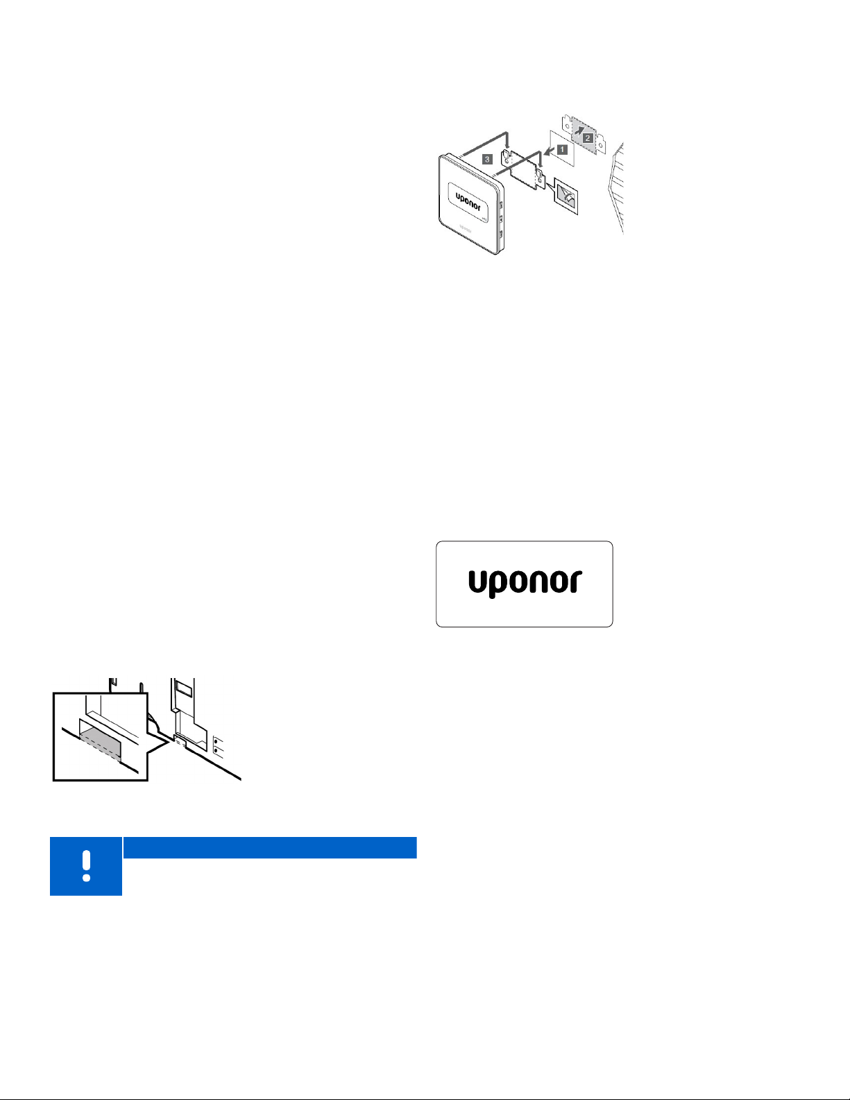
Attaching the Thermostat to a Wall
The thermostat
packaging includes
hardware for the
following three
attachment options:
• Wall bracket and
anchors
• Wall bracket and
adhesive strips
• Directly mounting
Figure 5-9: Attach thermostat
Once all the mounting brackets are in place and mounted
to the wall, make sure each thermostat is labeled for
identification. Be sure to take the thermostats with you.
This will make registering them to the Controller(s) an
easier process.
on the wall
Powering Up the Thermostats
Remove the plastic transportation strip from the battery to
start the thermostat.
The thermostat uses a single CR2032 3V button cell lithium
battery which provides about two (2) years of battery life if
it is positioned within radio range of the controller. Ensure
that the battery is correctly inserted in the thermostat.
• The Mini Sensor (T-161)
(part number A3800161)
will perform a self-test
for approximately 10
seconds when starting
Figure 5-10: Digital
Thermostat (T-169)
display at startup
up, and the LED flashes
during this period.
• The Digital Thermostat
(T-169) (part number
A3800169) will
perform a self-test
for approximately 10
seconds when starting
up and will display
the current software
version.
Note
Remove the breakout tab on the thermostat case
when installing a floor sensor.
uponor.com l 19
Page 20
Chapter 6:
Wiring
This section explains how to wire various hardware
components in the Smatrix Pulse system. Before beginning
the wiring process, ensure all hardware is mounted and
installed per the instructions in Chapter 5: Installation.
Controller
Connecting the Actuators
Refer to the following information to properly connect the
actuators.
Note
Each thermostat can control one or more channels
and will control the associated actuator output.
To simplify installation and maintenance, Uponor
recommends wiring actuators controlled by the
same thermostat in sequence to the channels.
Note
Uponor recommends identifying the thermostat
room name or zone number with individual loops
to be controlled on the manifold.
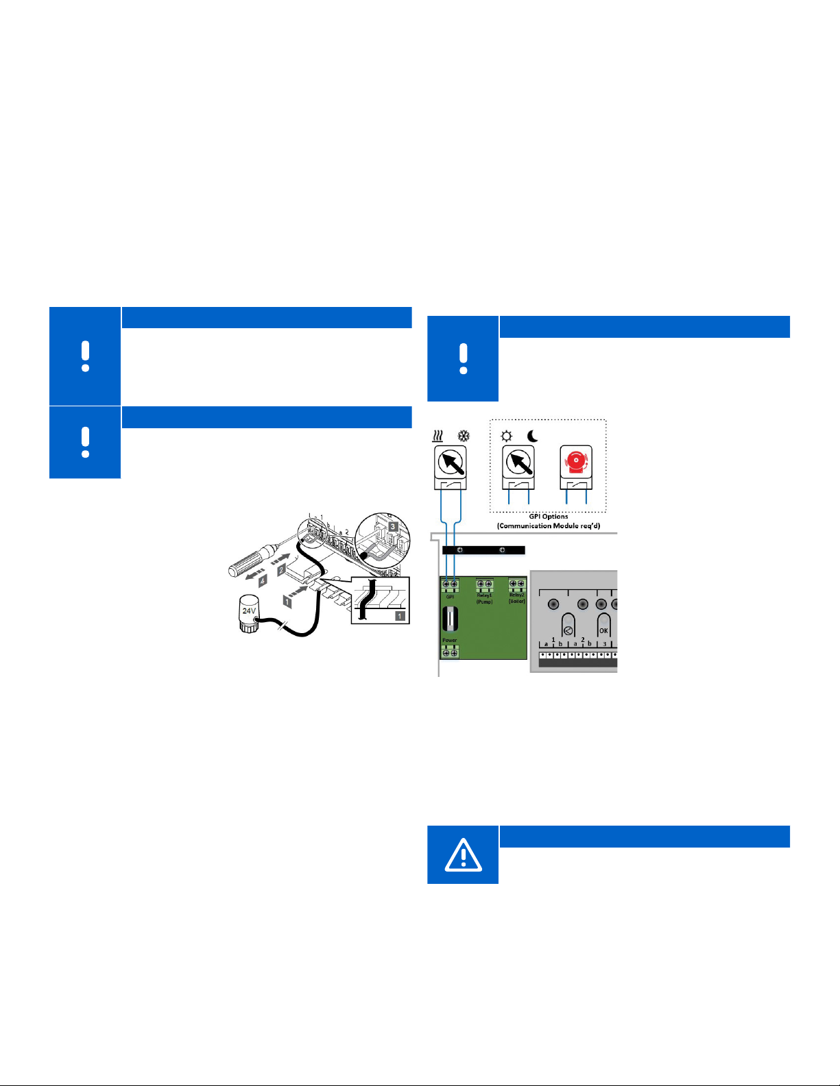
1. Remove the cover
from the controller
(and Expansion Module,
if installed).
2. Route the wires from
the actuator through
the cable entries in
the bottom of the
Controller case.
3. Ensure the two actuator
wires are stripped to
approximately
4. Using a small screwdriver, press and hold the white
button on the quick connector.
5. Insert the wire into the opening.
6. Remove the screwdriver from the quick connector.
7. Repeat for the second wire and for the additional
actuators.
/88" (9.5 mm).
Figure 6-1: Connecting
actuators
General Purpose Input (GPI) Switch
The controller includes a set of terminals that can be
used to change system operation. The default operation
is set for Heating/Cooling switchover. When the switch is
open, the system will be in Heating mode. When closed,
it switches the system over to Cooling mode. The GPI can
also be used to change the system from Comfort to ECO
mode (setback) but will require the installation of the
Communication Module and the Smatrix Pulse App to
change this setting.
Note
In systems where a Communication Module is
installed, the functionality of the GPI is selected
in the Installer Settings or in the System Settings
Menu.
• Ensure the power is
disconnected from both
the Controller and the
Heating/Cooling switch
source
• Remove the cover from
the Controller.
• Open the wiring
compartment using a
T-10 bit.
• Route the wires from the
Heating/Cooling switch
through the cable entry
above the contacts.
• Ensure the two actuator
Figure 6-2: GPI wiring
Caution!
If using the GPI for Comfort/ECO mode, use only
one switch for the entire system.
wires are stripped to
approximately
(9.5 mm).
• Insert the wires into the
terminal blocks and
tighten with a small
screwdriver.
/88"
uponor.com l 21
Page 21
Output Relays
The Controller includes sets of output terminals that can
be operated independently to control external equipment,
such as a pump or boiler (default). Table 6-1 shows the
various options for these outputs if a Communication
Module is installed in the system. This table applies to
options for the Primary Controller (connected to the
Communication Module).
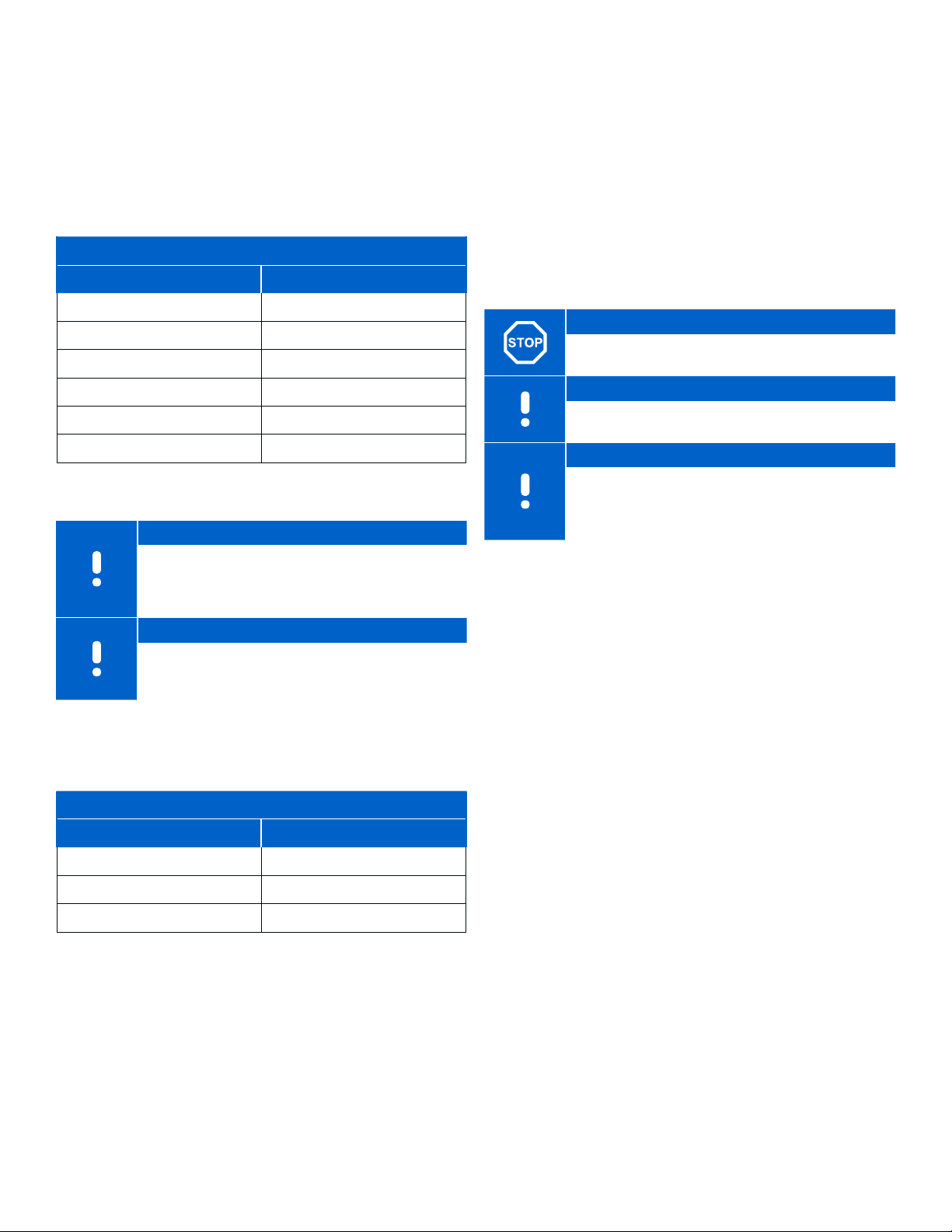
Primary Controller
Relay 1 Relay 2
Pump (default)
Pump
Pump
Chiller
Pump
1
1
1
1,3
1
Not Configured Not Configured
Table 6-1: Relay Outputs
Note
A Relay Module can be used in installations where
the distance between the device(s) and the
Controller makes wiring difficult or if more outputs
are needed.
Note
All relays are dry contacts and require a power
source.
If a Controller is installed in the system as a sub-Controller
(connected to an Antenna), the options for assigning
functionality is different and limited.
Sub-Controller
Boiler (default)
H/C Switch
3
Dehumidifier
Boiler
Comfort/EC0
5
6
Relay Functionality Notes for Tables 6-1
and 6-2
1
H/C Switch and Chiller is only available when cooling is activated
2
Function only available when Pump management is set to Individual,
otherwise "Not used" is shown in the Smatrix Pulse App.
3
Function only available when cooling is activated.
4
Function only available when cooling is activated, otherwise "Not used" is
shown in the Smatrix Pulse App.
5
Function only available during relative humidity control (in cooling, no
fan coils).
6
This function is also used when connecting a ventilation unit.
Relays 1 and 2
Warning!
Risk of electrical shock! Disconnect or remove
power prior to making electrical connections.
Note
Additional relay will be required when wiring to a
pump or circulator. See wiring schematics.
Note
Chiller relay function requires a Communication
Module and must be set in Installer Settings during
initial configuration, or in the System Settings
Menu.
• Remove the cover from the Controller.
• Open the wiring compartment using a T-10 bit.
• Route the wires from the pump relay through the cable
entry above the contacts.
• Ensure wires are stripped to approximately
• Insert wires into terminal blocks and tighten with a small
screwdriver.
Relay 1 can be wired to a pump (default) or chiller as
shown in Figure 6-3 and will require the Communication
Module to change the default functionality.
/88" (9.5 mm).
Relay 1 Relay 2
2
Pump
Pump
2
H/C Switch
Dehumidifier
Not Configured Not Configured
Table 6-2: Relay Outputs
22 l Smatrix Pulse | Installation and Operation Manual
4
5
Page 22
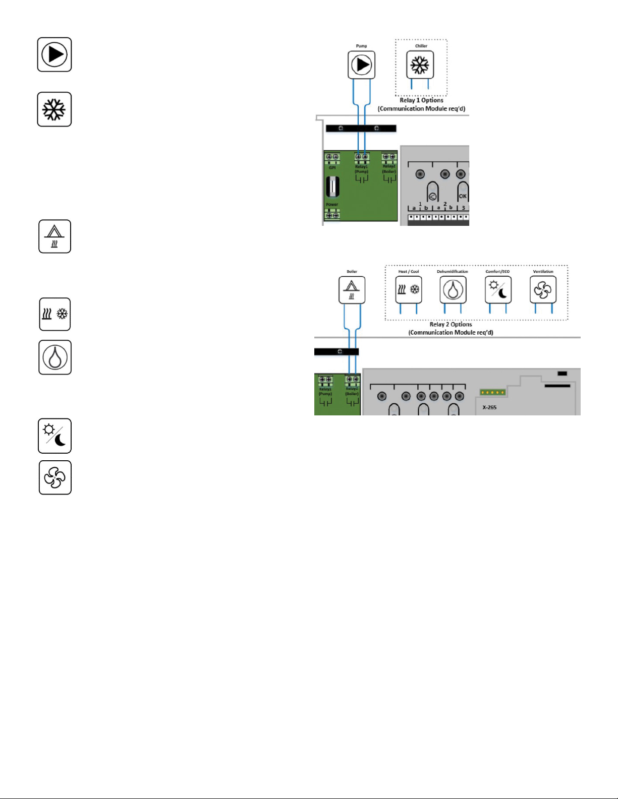
Pump: The output will close (turn on) when there
is a demand for heating or cooling. The relay will
open when the heating or cooling demand has
ended.
Chiller: The output will close (turn on) when the
system mode is set to cooling and there is a
cooling demand. The relay will open when the
cooling demand is met, or the mode is changed
to heating.
Relay 2 can be wired to a boiler (default) or other
options as shown in Figure 6-4 and will require
the Communication Module to change the default
functionality.
Boiler: The output will close (turn on) when there
is a heating demand. The relay will open when
the heating demand has ended. See Pump
Management section on page 13 for additional
information on setting pump operation to
Individual or Common.
Heat/Cool: Heating is activated when the relay
is open; cooling is activated when the relay is
closed.
Figure 6-3: Relay 1 options
Dehumidification: The dehumidifier starts (relay
closed) when the relative humidity setpoint
is reached when in cooling mode. It will open
when the minimum run time of 30 minutes has
finalized and when the relative humidity has
decreased below the defined RH setpoint.
Comfort/ECO: The relay closes when ECO mode
is activated and open when the system returns
to Comfort mode.
Ventilation: The relay is closed when the
system is set to ECO. The ventilation unit must
be setup to lower its speed (see manufacturer’s
specifications) when the input is closed (ECO),
and to switch back when the input is opened
again (Comfort).
After all actuator and wiring connections are complete,
it is now time to power up the controller. Close the wiring
compartment and plug the controller into a 115V wall
outlet.
Figure 6-4: Relay 2 options
Relay Module (M-263)
The relay module adds two extra output relays to the
controller increasing the total amount of controller output
relays to four (4). This presents an option to control remote
components (within radio range) otherwise wired to the
Controller and/or up to four (4) components by the same
Controller.
If more than one Controller is available in the system, one
Relay Module per Controller can be used.
If conventional forced-air heating and cooling equipment
or fan coils are installed, a maximum of four (4) Relay
Modules can be used per Controller.
The function for the Relay Module is set in Installer Settings
during setup (requires a Communication Module). The
tables below show the available functionality depending
on the device it is linked to.
uponor.com l 23
Page 23
Primary Controller
Relay 1 Relay 2 Relay 3
Pump (default)
Pump
Pump
Chiller
Pump
1
Boiler (default) Not Configured
1
1
1, 3
1
H/C Switch
Dehumidifier
Boiler Not Configured
Comfort/EC0
2
5
6
Not Configured
Not Configured
Not Configured
• Remove the cover from the relay module using a small
flathead or Phillips screwdriver.
• Route the wires from the heating/cooling equipment
through the cable entry below the contacts.
• Ensure the two actuator wires are stripped to
approximately
/88" (9.5 mm).
• Insert the wires into the terminal blocks and tighten.
• Replace the cover.
• Apply 24V power supply to the Relay Module.
Not Configured Not Configured Not Configured
Table 6-3: Primary Controller Relay outputs
Sub-Controller
Relay 1 Relay 2 Relay 3
2
Pump
2
Pump
Not Configured Not Configured Not Configured
H/C Switch
Dehumidifier
2
5
Not Configured
Not Configured
Table 6-4: Sub-Controller Relay outputs
Forced Air/Fan Coils
Relay 1 Relay 2 Relay 3
Heating Cooling Fan
Table 6-5: Forced Air/Fan Coils Relay outputs
Caution!
Make sure the power is off (or disconnected from
the device(s) being wired to the Relay Module.
Note
Additional Relay Module will be required when
wiring to a pump or circulator. See wiring
schematics.
Note
Chiller relay function requires a Communication
Module and must be set in Installer Settings during
initial configuration, or in the System Settings Menu.
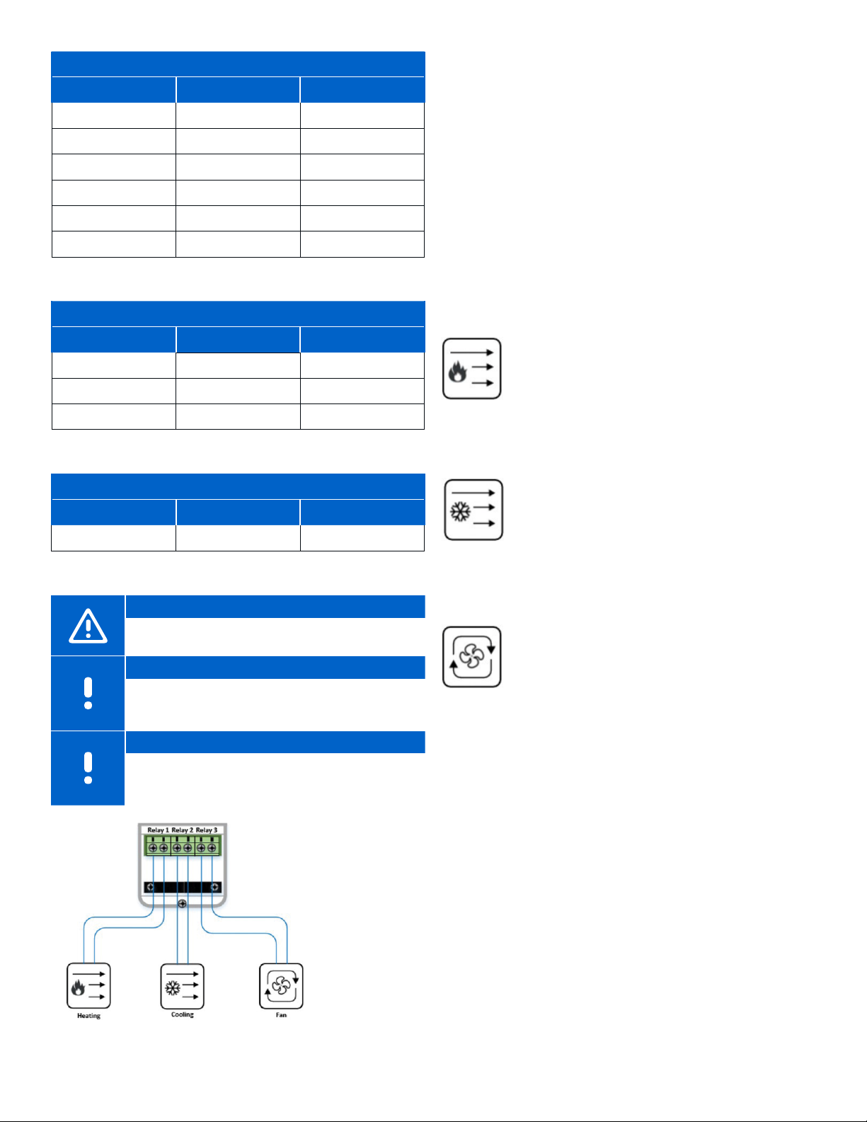
The Relay Module can be wired to a furnace/air
conditioning system or fan coil unit as shown in Figure
6-5 and will require the Communication Module to set up
this functionality. The Relay Module outputs provide the
following operation:
Heating: The output will turn on (close) for
forced air heating in Heating mode when the
room temperature linked to the Relay Module
falls below its set temperature. Activation will
depend on the rate that the temperature is
falling. The Relay Module will open once the
room temperature reaches the desired set
temperature.
Cooling: The output will close for forcedair cooling in Cooling mode when the room
temperature linked to the Relay Module rises
above its set temperature. Activation will
depend on the rate that the temperature is
rising. The Relay Module will open once the
room temperature reaches the desired set
temperature.
Fan: This output will close when a need for
heating or cooling is active on the Relay
Module and open when the active function
has ended. If recirculation is needed, the fan
operation can be set manually through the
Smatrix Pulse App.
When the relay module is successfully powered up, the LED
will flash red and then turn solid green to indicate normal
run mode. The relay LED will turn red when there is an
active call for heating and blue for cooling.
Figure 6-5: Relay Module wiring
24 l Smatrix Pulse | Installation and Operation Manual
Page 24
Thermostats
The external temperature sensor input can be used
to connect a floor temperature sensor on the Digital
Thermostat (T-169) (part number A3800169) and Mini
Sensor (T-161) (part number A3800161). This sensor can
be used to maintain minimum floor temperatures and
protect wood flooring. Minimum and maximum values
can be set or modified through the Smatrix Pulse App or
on the Digital Thermostat if no Communication Module is
installed in the system.
Wiring the Floor Sensor (optional)
Caution!
If more than one hour has passed between
startup of the thermostat, and the sensor
wires are connected, remove the battery from
the thermostat, wait 30 seconds, and reinsert
the battery again. The thermostat will now be
configured with a floor sensor.
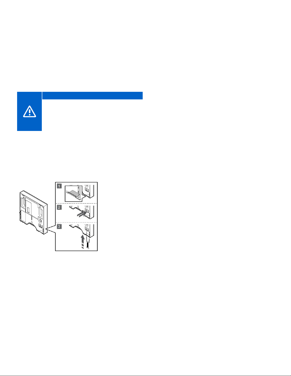
• Remove the breakout plastic on the back of the
thermostat.
• Press the push buttons on the connection terminals.
• While pressing the push buttons, insert the two wires from
the sensor cable (non-polarized) into the connection
terminal.
Powering Up the Thermostats
Remove the plastic transportation strip from the battery to
start the thermostat.
The thermostat uses a single CR2032 3V button cell lithium
battery which provides about two (2) years of battery life if
it is positioned within radio range of the controller. Ensure
that the battery is correctly inserted in the thermostat.
The A3800169 Digital Thermostat (T-169) will perform a
self-test for 10 seconds when the transportation strip or
the battery has been inserted. Allow the thermostat to
complete the self-test prior to linking to a Controller.
The A3800161 Mini Sensor (T-161) will also perform a selftest for 10 second when the transportation strip or the
battery has been inserted. The LED on the front will flash
during start up. Allow the sensor to complete the self-test
prior to linking to a Controller.
Figure 6-6: Floor sensor wiring
uponor.com l 25
Page 25
Chapter 7:
Connecting Wireless Devices
After mounting the hardware and wiring the devices,
the next step in the installation is connecting the various
devices wirelessly.
With the Smatrix Pulse system, the true wireless features
make the hardware more flexible and easier to install. This
section will take the user through the various options to
“link” the devices together given the following options:
• Linking a thermostat to a Controller
• Linking a thermostat to a Relay Module
• Linking a Controller to a Relay Module
• Linking a sub-Controller to a Primary Controller
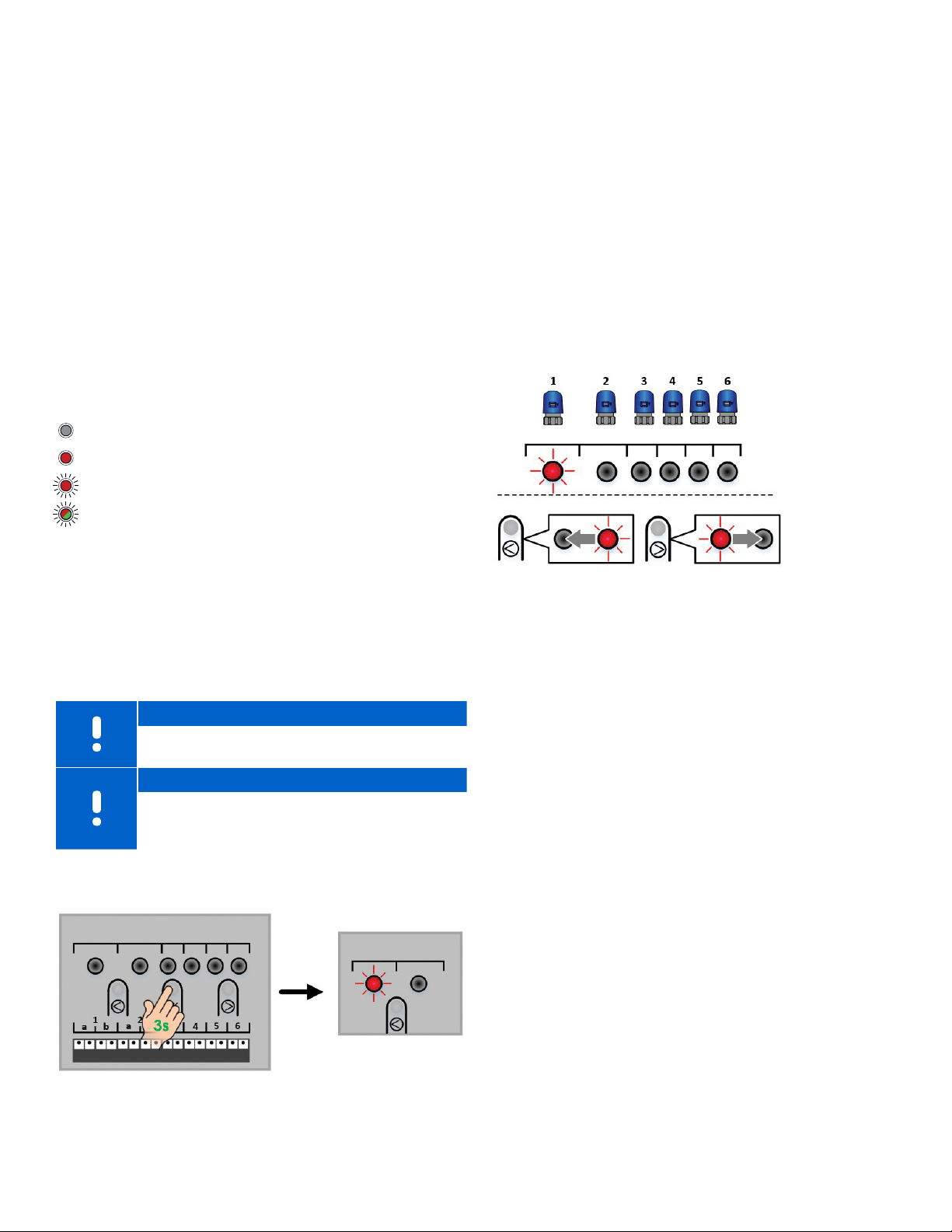
LED Guide
LED is unlit and dark (no color)
LED is on solid
LED is on flashing
LED is alternating colors
Linking a Thermostat to a Controller
It is necessary to link a thermostat to a Controller so the
thermostat can pass information to the Controller about
room temperatures, set temperatures, etc. The Controller
will process the information and make decisions based on
the system configuration and mode to operate the various
heating and cooling components.
Note
A thermostat can only be linked to a single
Controller.
Note
Thermostats must be linked to a Controller for
them to appear on the Smatrix Pulse App.
Use the following steps to link a thermostat to a Controller.
• Activate the registration mode by pressing the OK button
on the Controller for three (3) seconds. The Power LED
changes from solid green to solid red.
• The Controller is in registration mode when the LED for
Channel 1 flashes red. If a thermostat has already been
linked, the first channel available will flash red.
A previously linked channel will appear solid green.
• If the LED (or channel) flashing is not correct for the
actuator the thermostat will control, used the < and >
buttons to move the flashing red LED to the preferred
channel.
Figure 7-2: Assigning a thermostat
• Press the OK button to enter or assign that thermostat.
The link will be confirmed with LED turning solid green,
and the next available channel LED will begin to flash red.
• If more than one channel will be assigned to a
thermostat, select the next channels to be registered to
the thermostat and press OK. Once all selected channel
LEDs are solid green, go to the thermostat.
• Put the thermostat into “pairing” or registration mode:
• Digital Thermostat: Press and hold the ▲ and ▼ buttons
on the side of the thermostat until a symbol for an
antenna appears in the display. A check will briefly
appear when the registration is complete and then
revert to current room temperature.
• Mini Sensor: Press the button and hold on the back of
the thermostat for five (5) seconds. The LED on the front
of the stat will begin to flash. The LED will turn off when
the registration is complete.
• Once the registration between the thermostat and the
Controller is complete, the LED (or LEDs) set up previously
will turn solid green, and the next available (or open)
channel will flash red.
• Repeat these steps for additional thermostats.
Figure 7-1: Linking a thermostat to a Controller
uponor.com l 27
Page 26
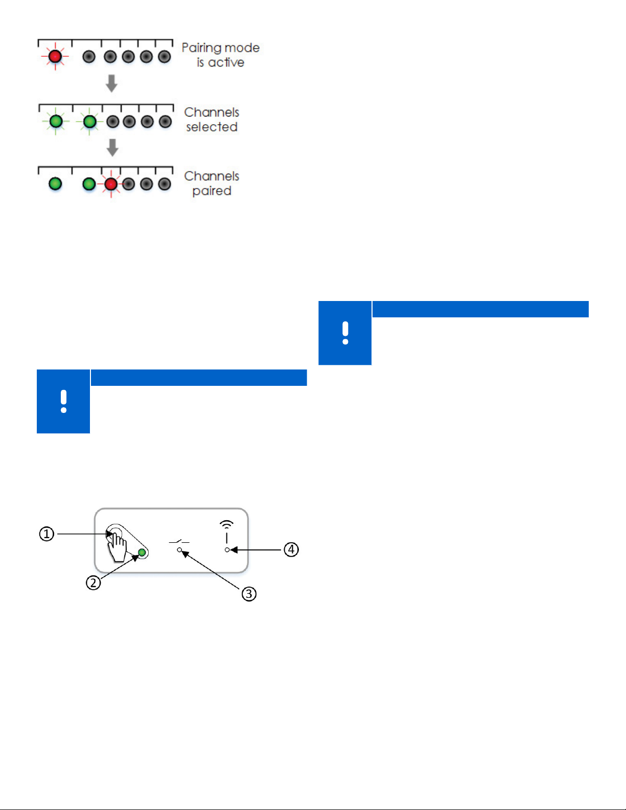
Figure 7-3: Pairing the thermostats
Linking a Thermostat to a Relay Module
The A3800169 Digital Thermostat (T-169) can be
linked directly to a Relay Module. This can be useful
in installations when the thermostat will control a
conventional forced-air system with air conditioning
or a fan coil or in instances where getting wiring back
to the mechanical room for a zone pump in a garage
application is an issue. The Relay Module, depending
on the system mode, will turn on the relays required for
heating and cooling.
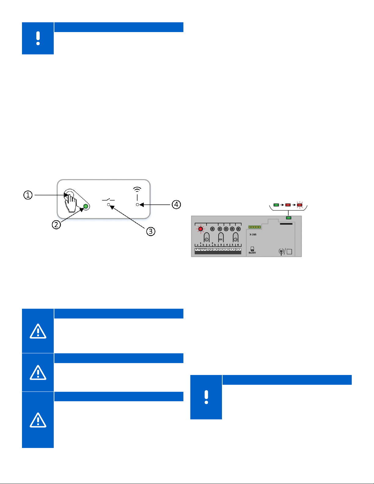
1. This will be used to place the Relay Module into pairing
mode or to clear a link or registration to a thermostat
2. This will show the status of the Relay Module based on
the various modes of operation. During power-up, this
LED will flash red and green for a short duration. Once
the Relay Module is ready for operation, this LED will turn
green.
3. During normal operation, a solid red LED will indicate
active operation of the heating equipment and the
appropriate Relay Module(s) close. A solid blue LED
indicates active cooling.
4. This LED is used during the linking process of the
thermostat to the Relay Module (along with relay to the
Controller). This LED has the following states:
• Dark or unlit – Relay Module is not in the linking
(or pairing) mode.
• Slow flashing red – Relay Module is in linking mode.
• Fast flashing red – Relay Module is completing the
linking process with the thermostat.
Note
To change the Relay Module operating mode,
power down the Relay Module and wait for 10
seconds. Press and hold the button while restoring
power and the LED will flash once (normal).
Note
The thermostat should be linked (or registered) to
the Controller first, even though it will not control
actuators. See the previous step for Linking a
Thermostat to a Controller.
Before proceeding to linking the devices, familiarize
yourself with the various items on the Relay Module
and their status/operation:
Figure 7-4: Relay Module status items
28 l Smatrix Pulse | Installation and Operation Manual
Page 27
Use the following steps to link a thermostat to a Relay
Module:
• Ensure the Relay Module is powered up and the LED is on.
• Activate the registration mode on the Relay Module by
pressing the button for three (3) seconds. When done
correctly, the linking LED will begin to slow flash red.
Caution!
If no button on the thermostat is pressed for about
eight (8) seconds, while in a sub menu, the current
values will be saved, and the software exits to the
Settings Menu. After 60 seconds, the Relay Module
will return to normal run mode.
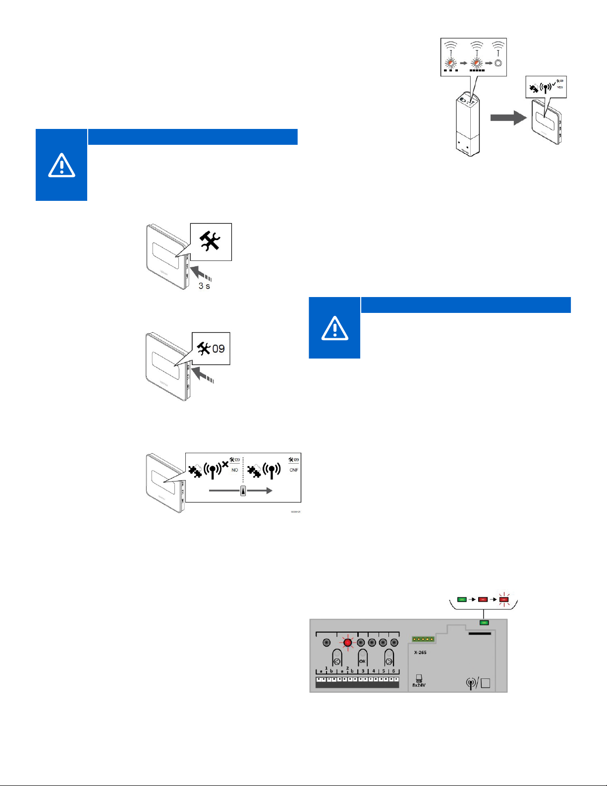
• Enter the
configuration
mode on the
Digital Thermostat
by pressing and
holding the middle
button for about
three (3) seconds.
Figure 7-5: Press and hold middle
button for three (3) seconds
• Once the menu is
activated, press the
up (or top) button
until 09 is shown in
the top right corner.
Figure 7-6: Press top
button until 09 is shown
in right top corner
• Press the middle
button and a line will
appear under 09.
• Press the top
button until “CNF”
is displayed in the
screen.
Figure 7-7: Press top button until
CNF displays on the screen
• Once successfully paired,
the LED will flash quickly
on the relay and a
check will appear on the
thermostat screen.
• Press the OK (middle)
button to confirm the
change.
• Exit the Settings Menu by
pressing and holding the
OK button for three (3)
Figure 7-8: Successful pairing
seconds.
Linking a Relay Module to a Controller
A Relay Module can directly link to a Controller. Each
Controller can only have one Relay Module linked to it to
mirror or duplicate the pump and boiler outputs. This can
be useful in installations when getting wiring back to the
mechanical room for a zone pump and/or boiler is an
issue in retrofit or remodel applications.
Caution!
When linking a Relay Module to a Controller
and using the “second layer” of pairing, other
Controllers will pair to Channel 1 and the Relay
Module will pair to Channel 2.
Use the following steps to link or register a Relay Module to
a Controller:
• Enter the pairing mode. Press and hold the OK button on
the Controller until the LED for the first available channel
begins to flash Red.
• Using the < or > buttons, move the flashing LED from the
channels to the power LED on the Controller. The LED will
begin to flash red. This secondary layer is for linking Relay
Modules and other controls to Controllers.
• Press the OK button and the LED for Channel 1 will begin
to flash red.
• If done correctly, the LED for Channel 1 will begin to flash
red and the power LED will start flashing in a pattern (long
flash, short unlit flash, long flash, etc.).
• Press the > button to move the flashing red LED to
Channel 2.
Figure 7-9: Enter pairing mode
uponor.com l 29
Page 28
Note
The Relay Module will only link to Channel 2 on
Controllers.
• Select (or lock) the channel by pressing the OK button.
The LED should begin to flash green.
• Make sure the Relay Module is powered up and the power
LED (2) is on solid green.
• Activate the registration mode on the Relay Module by
pressing the registration button (1) for three (3) seconds.
When done correctly, the link LED (4) will begin to slow
flash red.
• The link LED (4) on the Relay Module will begin to
begin flashing faster, and the LED for Channel 2 on the
Controller will turn to solid green. At this time, the Relay
Module is paired with the Controller.
• Press and hold the OK button to exit pairing mode. When
done correctly, the power LED will be solid green.
To link a sub-Controller to a Primary Controller, use the
following steps:
• Enter the pairing mode on the Primary Controller (one
connected to the Communication Module). Press and
hold the OK button on the Controller until the LED for the
first available channel begins to flash red.
• Using the < or > buttons, move the flashing LED from the
channels to the power LED on the Controller and it will
begin to flash red.
• Press the OK button.
• If done correctly, the LED for Channel 1 will begin to flash
red, and the power LED will start flashing in a pattern
(long flash, short flash, long flash, etc.).
• Repeat the steps for the sub-Controller to be paired with
Primary Controller.
• Enter the pairing mode on the sub-Controller. Press and
hold the OK button on the Controller until the LED for the
first available channel begins to flash red.
• Using the < or > buttons, move the flashing LED from the
channels to the power LED on the Controller, and it will
begin to flash red.
Figure 7-10: Relay Module status items
Linking a Controller to a Sub-Controller
When multiple Controllers are installed in a system, only
one can be connected to a Communication Module.
This unit is considered the Primary Controller. All other
Controllers will connect to Antennas and are considered
sub-Controllers.
Caution!
For thermostat information to appear on the
Smatrix Pulse App or for Over The Air (OTA)
updates to be installed and updated, all subControllers will need to be linked to the Primary
Controller.
Caution!
The Controller will time out after about 10 minutes
of inactivity and revert to normal operation. The
timer will be reset when a button is pressed or if a
device has been Registered.
Caution!
If a Controller has been connected to a
Communication Module, disconnect the
Communication Module, and restore it to the
sub-Controller state by performing a factory reset.
Existing sub-Controllers in the system must then
either reset system device Channel 01 or register to
another Primary Controller.
Figure 7-11: Pair a sub-Controller to
a Primary Controller
• Press the OK button.
• If done correctly, the LED for Channel 1 will begin to flash
red, and the power LED will start flashing in a pattern
(long flash, short flash, long flash, etc.).
• Select Channel 1 and press OK to lock in the channel.
• Channel 1 LED on both the sub-Controllers turns solid
green and the registration is complete. Channel 1 LED on
the Primary Controller will continue to flash as additional
sub-Controllers can be paired during this time.
• Exit the pairing mode by pressing OK for three (3)
seconds on both controllers.
Note
The next sub-Controller can be registered within
10 minutes without the need to activate Channel 1
on the Primary Controller again. If the registration
times out, the process can begin again without
overwriting existing sub-Controller registrations.
30 l Smatrix Pulse | Installation and Operation Manual
Page 29
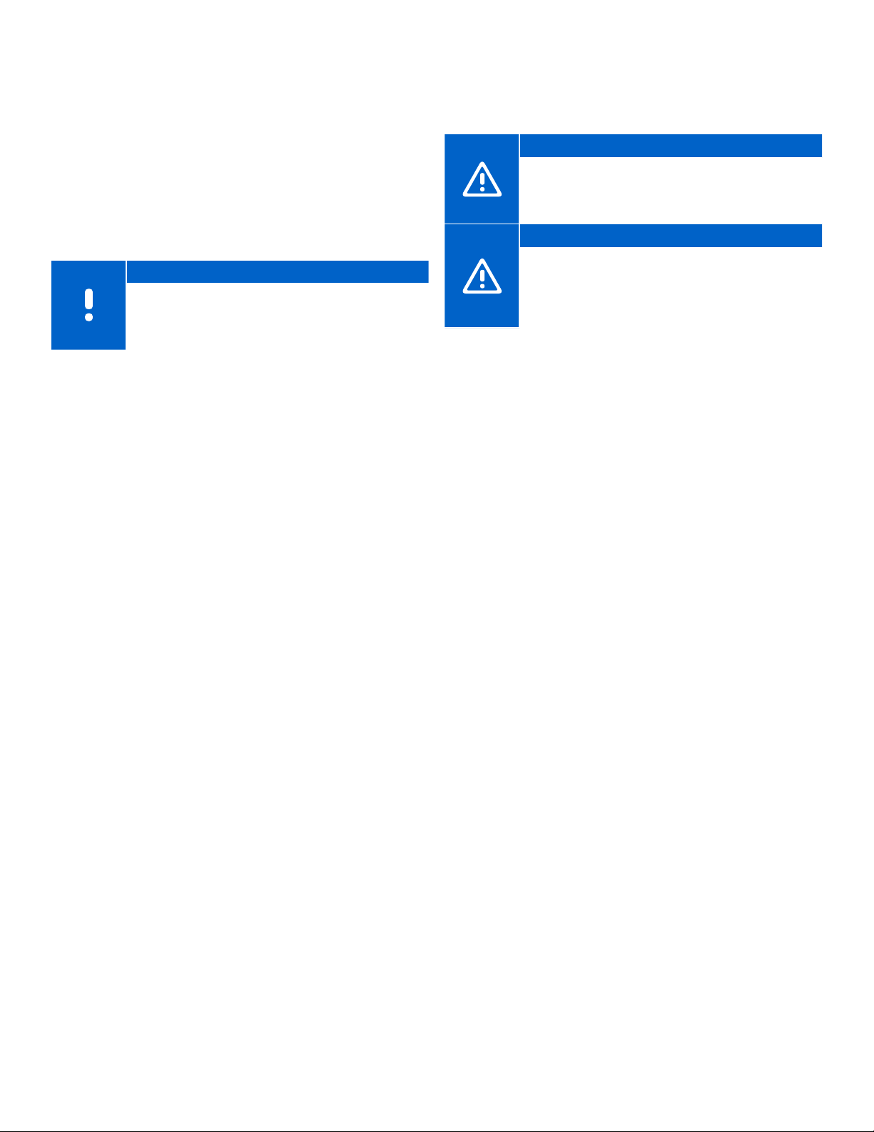
Chapter 8:
Clearing Setup Information or Resetting Devices
It may be necessary during the installation process to
clear portions of the setup and start over. The following
section will take the user through the steps needed
change the setup or restore the individual parts back to
their original factory settings.
Controller
Note
When removing the link between devices
(e.g., thermostats and Relay Module), Uponor
recommends performing the unpairing process
on both pieces of hardware.
Refer to the two options below to remove setup
parameters on Controllers that were done incorrectly.
Unpairing a Channel
Use this process when a channel is incorrectly assigned to
a thermostat.
• Enter the registration mode by pressing the OK button on
the Controller for three (3) seconds. The first unassigned
channel will begin to flash red.
• LEDs that are solid green are available to be unassigned.
• Using the < or > buttons, move the flashing red LED to
the channel you wish to remove. The LED will alternate
between green and red.
• Press and hold the < and > buttons for five (5) seconds.
• When the channel is unregistered, the LED will flash red.
• Press and hold the OK button on the Controller until the
LEDs turn off. The Controller has returned to normal run
mode.
• If unpairing a thermostat, Uponor recommends resetting
this device as well.
Clearing All Setup Information
Refer to this procedure to clear all setup information and
return the Controller to its factory, or default, state. This will
remove links to all devices in the system: Controllers, Relay
Modules, thermostats, etc.
Caution!
Resetting the Controller removes all registration
information and settings. Registration of
thermostats and system devices are once again
required.
Caution!
If resetting a sub-Controller, all remaining subControllers must be unregistered from the Primary
Controller (system device Channel 1). Register
the remaining sub-Controllers to the Primary
Controller again when finished.
• Make sure the Controller is in run mode (green LED in
upper-right hand corner of the Controller).
• Press and hold the <, OK, and > buttons for approximately
10 seconds until the power LED flashes and all channel
LEDs turn off.
• All parameters and settings are erased, and the
Controller will return to run mode.
Removing a Paired Relay Module
• Press and hold the OK button on the Controller until the
LED for the first available channel begins to flash red to
enter the pairing mode on the Controller and the power
LED will change from green (normal operation) to red
(linking mode).
• Using the < or > buttons, move the flashing LED from the
channels to the power LED on the Controller, and it will
begin to flash red.
• Press the OK button.
• If done correctly, the LED for Channel 1 will begin to flash
red and the power LED will start flashing in a pattern
(long flash, short flash, long flash, etc.).
• Press the > button to move to Channel 2 and this LED will
begin to flash green.
• Press and hold the <, OK, and > buttons for approximately
10 seconds until the power LED flashes and Channel 2 LED
will turn off.
• Press and hold the OK button on the Controller until the
power LED returns to green. The controller has returned to
normal run mode.
uponor.com l 31
Page 30
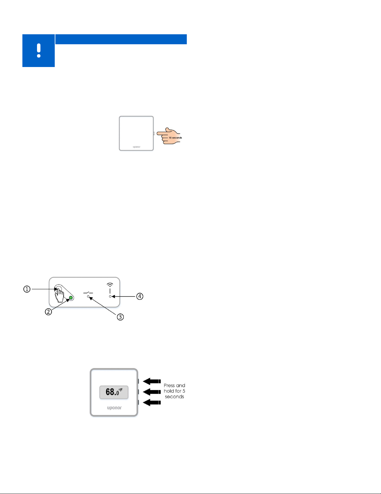
Resetting the Communication Module
Note
Performing this function will not affect the
Controller and thermostat-related settings.
This function resets the Communication Module to factory
settings and is mostly used when transferring the installed
system to a new owner. Some setup information will be
reset, such as room names.
• Press the button for about 10
seconds until the function LED
turns off.
• Release the button and the
Communication Module
reboots to factory settings.
• When the LED starts flashing
red, unplug and plug in the
controller to send installation data to the Communication
Module.
Figure 8-1: Resetting the
Communication Module
Resetting the Relay Module
The following procedure will remove any pairing or reset to
the factory (default) state.
• Press and hold the registration button (1) until all the LEDs
on the Relay Module start flashing.
• Release the button (1) after all LEDs have turned off.
• The Relay Module has now cleared any registrations and
is reset to factory values.
Resetting the Mini Sensor (T-161)
• Remove the thermostat from the wall.
• Remove the battery.
• Press and hold the registration button on the back of the
thermostat while re-inserting the battery.
• Release the button after 10 seconds when the LED begins
to flash.
Finishing the Installation
Prior to making the system operational, perform a
complete review of the installation.
• Ensure the thermostats are working and the batteries
are installed. Turn thermostat setpoints to maximum to
obtain a heating demand and make sure the actuators
are opening.
• Set thermostats to the desired room set temperatures
• Close the covers of the Controller.
• Make sure all thermostats are in the room or space which
they will control.
• Print and fill in the “Installation report” (separate
downloadable document).
• Provide the manual QR code, app information, and the
Installation Report to the end user.
Actuator Test Mode
During the final steps of the installation process, it may be
necessary to test or cycle the actuators. Some actuators
may ship in a semi-open state to allow easier installation
on the manifolds. Failure to fully cycle the actuators could
lead to overheating. To enter the Actuator Test Mode, use
the following steps:
Figure 8-2: Resetting the Communication Module
Resetting the Digital Thermostat (T-169)
• Press and hold all three (3) buttons on the side of the
thermostat for five (5) seconds
• The screen will go
blank temporarily
and restart showing
the software version.
• Once this is
complete, the
screen will show
the current room
temperature.
Figure 8-3: Resetting the
Digital Thermostat (T-169)
• Press the > button while in run mode (normal operation)
to access the Actuator Test Mode. If not in run mode,
press and hold the OK button for three (3) seconds to exit
to run mode
• Select a channel using the < and > buttons to move the
pointer (LED flashes red) to the preferred channel.
• Press the OK button to activate the Actuator Test Mode
for the selected actuator.
• To end the Actuator Test Mode, select the active channel
and press the OK button.
32 l Smatrix Pulse | Installation and Operation Manual
Page 31
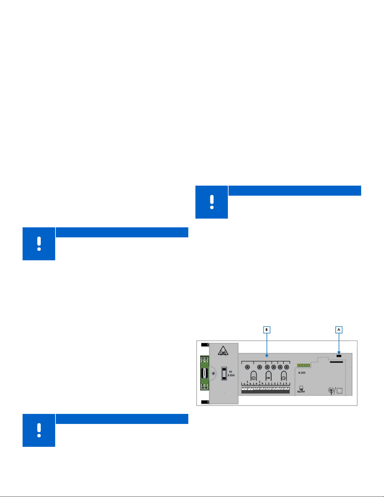
Chapter 9:
System Operation
The Controller operates the underfloor heating/cooling
installation according to customer needs. The user adjusts
temperatures via thermostats located in each room, or
if installed with the Smatrix Pulse App (which requires a
Communication Module).
As soon as the temperature measured at a thermostat
is lower (heating mode) or higher (cooling mode) than
the setpoint temperature, it creates a demand to the
Controller to change the room temperature. The Controller
opens the actuators according to current operating mode
and other settings. Once the thermostats signal that the
set temperature is reached, this information is sent to the
Controller, and the actuators are closed.
The system supports different types of cooling methods
and is setup in the Smatrix Pulse App. Available cooling
methods in the Smatrix Pulse App include:
• Underfloor cooling via hydronic radiant loops
• Fan coils or conventional forced-air heating and cooling
equipment (connected to a relay module registered to a
room thermostat)
Note
Be sure to disable Autobalancing (in Installer
Settings) when air cooling or heating is installed
and configured.
In rooms where radiant cooling is allowed and a fan coil
is installed, radiant cooling is activated depending on the
rate the temperature is rising in the room. Second-stage
cooling (if installed) will activate based on the rate the
room temperature is rising.
Refer to the Smatrix Pulse App for more information about
these individual functions.
Operation with Schedules
Scheduling programs provide an option to switch
selected rooms between Comfort and ECO mode using
a 7-day program. This optimizes the installation and
conserves energy. When in the comfort mode, the rooms
/ thermostats will control room temperature based on
the user defined set temperature. When in ECO mode, all
zones or thermostats that are attached or assigned to a
schedule, the set temperature will change based on the
offset value, or ECO setback.
For example, if the ECO setback is set to 5, and the Comfort
set temperature is 68°F, the new room temperature the
system will control to is 63°F (68 – 5 = 63°F). In cooling
mode, the ECO setback would be added to the cooling
room set temperature.
Note
The Communication Module is required to access
the Smatrix Pulse App to create and adjust
schedules.
Controller LED Status
If not using the Smatrix Pulse App, Uponor recommends
occasionally checking the power LED on the Controller
for system status and alarms. The power LED flashes
continuously for general alarms. Determine which
thermostats are issuing alarms by removing the cover. If a
channel LED is indicating an error, check the function and
batteries of the registered thermostat.
Refer to the following information to determine the LED
status of the power (A) and channel LEDs (B) depending
on the mode of operation.
Normal Operation without using Schedules
When the system is running in normal mode:
• In Heating mode, the actuators are open when room
temperatures are lower than the temperatures set on
the thermostats.
• In Cooling mode, the actuators are open when room
temperatures are higher than the temperatures set on
the thermostats.
Note
If autobalancing is enabled, actuators could be
closed during a demand.
Figure 9-1: Controller LED locations
uponor.com l 33
Page 32
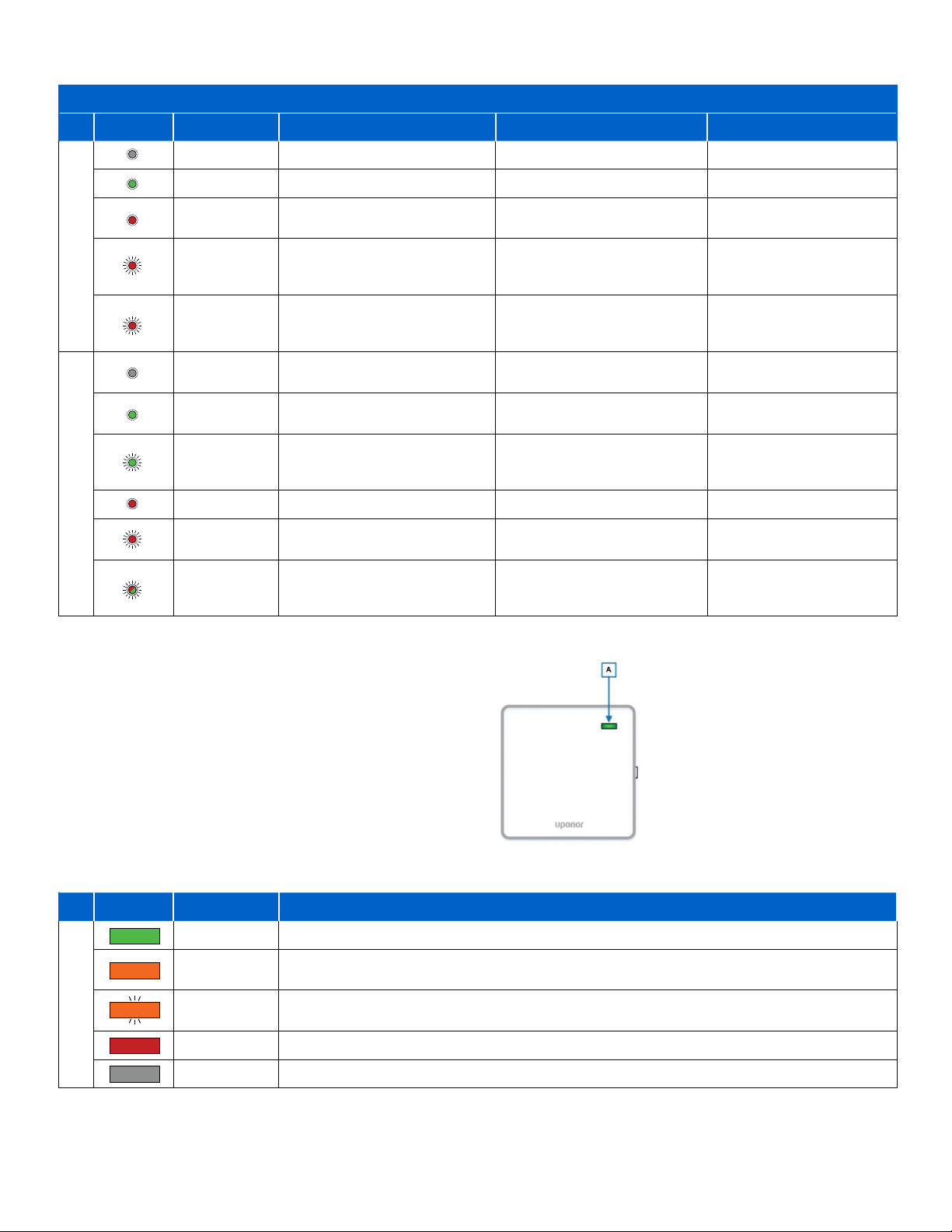
Controller LED Mode of Operation
Primary Controller
LED Status Description Run Registration Actuator Test
Dark (unlit) No power – –
Solid Green Controller is powered on – Power is On
Solid Red –
Power LED (A)
Channel LED(s) (B)
Flashing Red
Slow Flashing
Flashing Green –
Flashing Red
Red
Dark (unlit) No heating or cooling demand
Solid Green –
Solid Red Actuator is activated – The actuator is activated
Flashing
Green/Red
A problem has occurred
(e.g., lost thermostat)
Channel waiting to be activated
or thermostat communication
Table 9-1: Controller LED mode of operation
Registration active for linking
thermostats (first layer)
Registration active for linking
Controllers or Relay Module
(second layer)
Registration ready to link
–
–
Controllers (Channel 1 LED) or
Relay Module (Channel 2 LED)
Selector not pointed at the
channel or not registered
Thermostat is registered
to the channel(s)
Channel is available and
awaiting for thermostat
registration
–
Selector is pointed at a channel
that is already registered to a
thermostat
Selector is not pointed at
the channel or activated
Selector is pointed at the
–
–
–
–
–
channel
–
Communication Module
Like the Controller(s), the Communication Module
incorporates an LED that will provide feedback to the
status of the Smatrix hardware connecting to the Cloud.
Understanding the various colors of the status LED (A)
on the Communication Module will be beneficial in
troubleshooting issues with remote connectivity.
The following table shows the communication status
based on the color and state of the LED (A).
Communication Module LED Mode of Operation
LED Status Description Status
Solid Green Communication Module cloud connected with the user account created and internet access
Solid Orange
Flashing
Orange
Solid Red No connection to the router has been established
Status Indicator (A)
Dark (unlit) Power is off
Table 9-2: Communication Module LED mode of operation
Wi-Fi (or Ethernet) connection is established to the router with no internet access
(no user account created or there is a user account, but no internet access)
The Access Point is open, connected, and communication available connecting phone/tablet
via Wi-Fi.
Figure 9-2: Communication Module LED location
34 l Smatrix Pulse | Installation and Operation Manual
Page 33
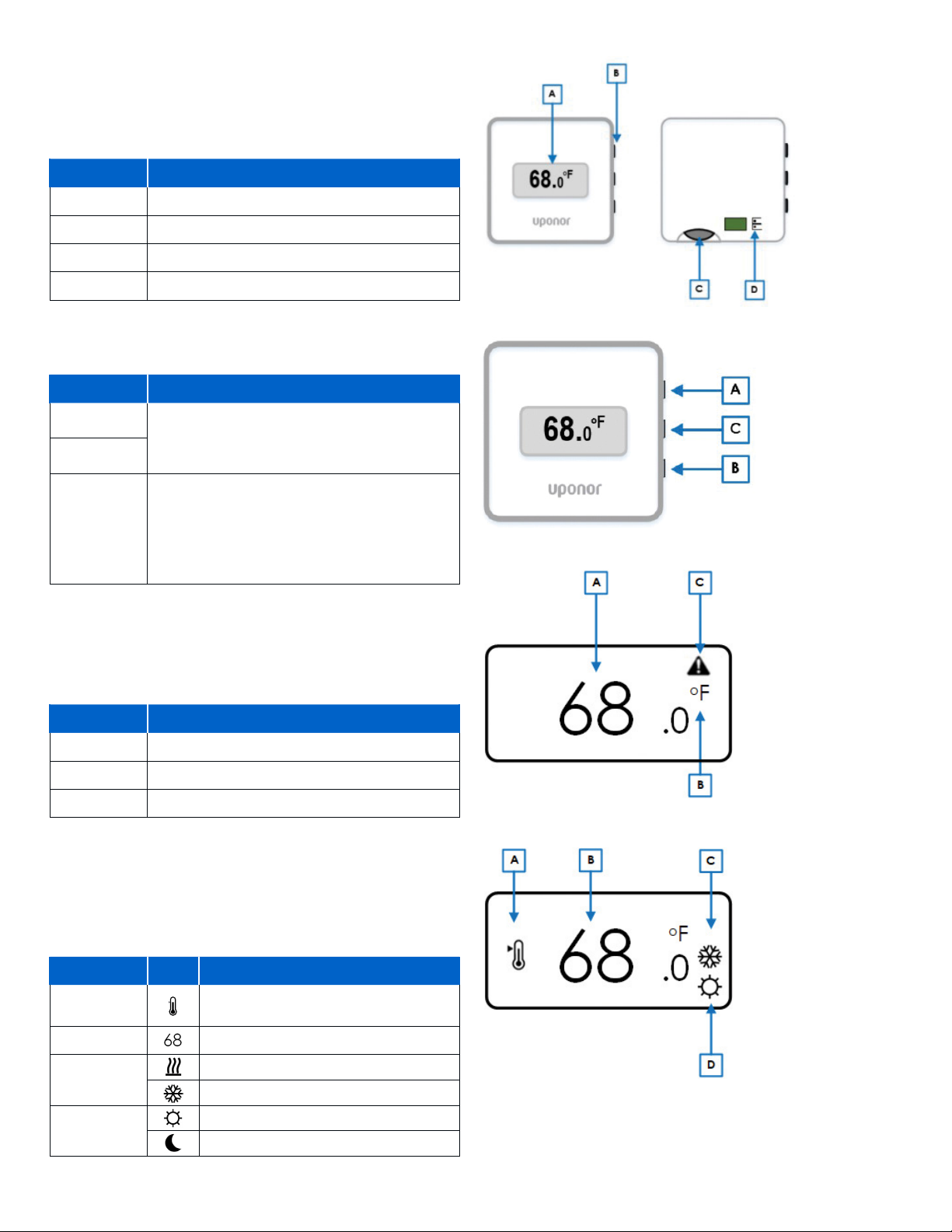
Digital Thermostat (T-169) Operation
The following are the key parts of the Digital Thermostat
(T-169).
Components
Reference Description
A Display
B Buttons
C Battery (CR 2032V)
D Sensor terminals (non-polarity sensitive)
Table 9-3: Digital Thermostat (T-169) components
Button Functions
Button Function(s)
A
B
C
The ▲ and ▼ for the following functions:
• Adjust setpoint temperature
• Modify settings menu parameters
The OK button is used to:
• Toggle between the current status and the
values of available sensors connected to the
thermostat
• Enter and exit the settings menu
• Confirm a setting
Table 9-4: Digital Thermostat (T-169) button functions
Display Mode
Figure 9-5 shows the different symbol and characters that
can be displayed when the thermostat is in the run mode.
Reference Description
A Room temperature
Figure 9-3: Operation components
Figure 9-4: Button functions
B Temperature units (°F or °C)
C Alarm warning
Table 9-5: Display mode
Changing Temperature Settings
Figure 9-6 shows all the possible symbols and characters
that can be shown on the display when changing the
desired set temperature.
Reference Icons Description
A
B Room set temperature
C
D
Table 9-6: Changing temperature settings
Indicates changing the setpoint
temperature
Heating demand
Cooling demand
Comfort mode
ECO (setback) mode
Figure 9-5: Display mode
Figure 9-6: Changing temperature settings
uponor.com l 35
Page 34
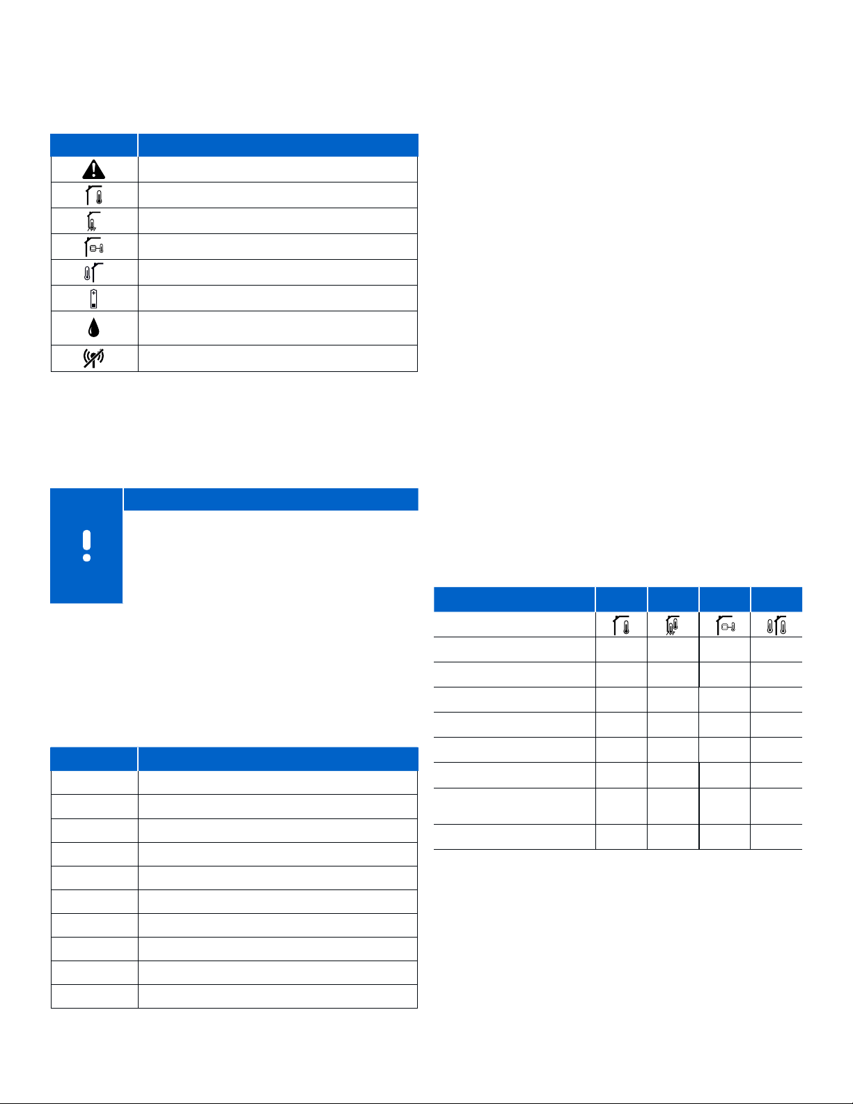
Alarms
This figure shows all the possible symbols and characters
that can be shown for an alarm on the display along with
the cause/meaning.
Icons Description
Alarm mode (shown with the following:)
Faulty indoor sensor
Faulty floor sensor
Faulty remote sensor
Faulty outdoor sensor
Low battery indicator
Relative humidity high limit (only shown in
cooling mode and if RH control is setup)
Communication failure
Table 9-7: Alarms
Menus for Digital Thermostat (T-169)
This section shows all the setting options for operating the
Digital Thermostat (T-169).
Note
If no button on the thermostat is pressed for about
eight (8) seconds, while in a sub menu, the current
values will be saved, and the software exits to the
Settings menu. About 60 seconds later, it exits to
run mode where the current room temperature is
displayed.
Menu 02: Heating/Cooling Changeover
This menu is not visible if the thermostat is registered to a
Controller. Heating/cooling changeover will be controlled
by a physical heating/cooling switch or in the Smatrix
Pulse App (requires Communication Module).
Menu 03: ECO Mode Setback Value
Default value: 39°F (4°C)
Setting range: 32 – 52°F (0 – 11°C), 1°F (0.5°C) increments
This is the setback temperature for whenever the system
is in ECO. The setting adjusts the current setpoint with the
set value. In Heating mode, the setpoint is reduced, and in
cooling mode it is increased. If the setback temperature
is set to 0, the thermostat will remain unaffected if a
program sets the system in ECO mode.
This menu is not visible if a Communication Module is
connected to the system. The setting is then available in
the Smatrix Pulse App.
Menu 04: Control Mode
This menu set the way an external sensor (if attached)
is used (remote, outdoor, etc.). If an external sensor
is connected to the thermostat, a control mode must
be chosen to accommodate the extra functionality of
the sensor. Current control mode options are Room
Temperature RT (default), Room and Floor Temperature
RFT, Remote Sensor RS or Room and Outdoor Sensor RO.
Refer to the table below for available information based
on the control mode selected.
RT RFT RS RO
To enter the Settings menu, use the following steps:
• Press and hold the OK button for about three (3) seconds.
• The settings icon and menu number are displayed in the
top-right corner of the display.
• Use the < or > button to change the numbers to locate a
sub menu (see list below).
Menu # Description
02 Heating/cooling changeover
03 ECO mode setback value
04 Control mode
05 High temperature floor limit
06 Low temperature floor limit
07 Cooling allowed
08 Display units
09 Relay Module integration
11 Room temperature calibration
12 Invert screen
Table 9-8: Digital Thermostat (T-169) menu descriptions
36 l Smatrix Pulse | Installation and Operation Manual
Room temperature
Alarm (if active)
Floor temperature
Remote temperature
Outdoor temperature
ECO/Comfort mode status
Active demand
(heating or cooling)
Relative humidity
Table 9-9: Control Mode menu
P P P P
P P P P
P P P P
P P P P
P P P P
P
P
P
Page 35
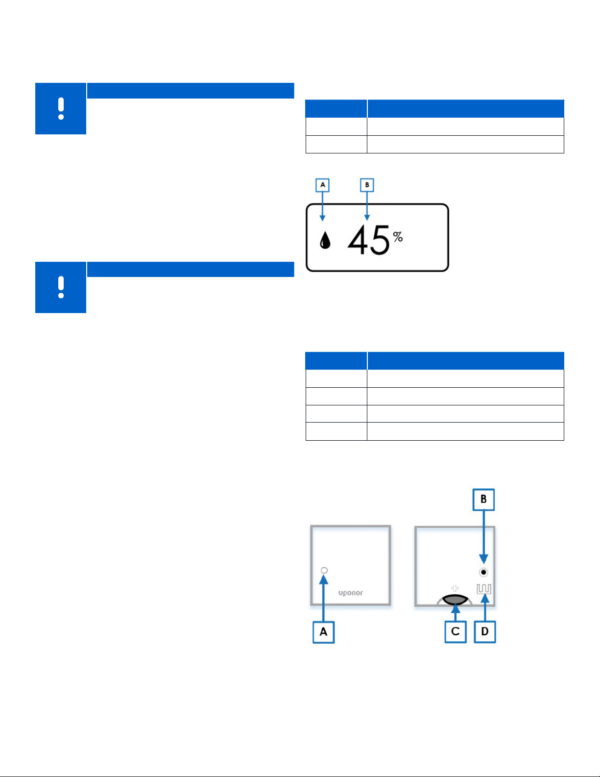
Menu 05: High Floor Temperature Limitation
Default: 78°F (26°C)
Setting range: 38 – 95°F (20 – 35°C), 1°F (0.5°C) increments
Note
This parameter cannot be set lower than the set
value in settings Menu 06 (low floor temperature
limitation).
Relative Humidity
The Digital Thermostat (T-169) also displays the relative
humidity level in the room or space. Pressing the OK button
three (3) times will display the following information:
Reference Description
A Relative humidity
In this menu, a limit on the highest allowable floor
temperature is set. This menu is only visible if control
mode RFT is activated in Menu 04. For systems with a
Communication Module, this menu only shows the set
value. Changes are done in the Smatrix Pulse App.
Menu 06: Low Floor Temperature Limitation
Default: 68°F (20°C)
Setting range: 50 - 86°F (10 – 30°C), 1°F (0.5°C) increments
Note
This parameter cannot be set higher than the set
value in settings Menu 05 High floor temperature
limitation.
In this menu a limit on the lowest allowable floor
temperature is set. This menu is only visible if control
mode RFT is activated in Menu 04. For systems with a
Communication Module, this menu only shows the set
value. Changes are done in the Smatrix Pulse App.
Menu 07: Cooling Allowed
This menu sets whether a room will receive cooling or not.
This menu is not visible if a Communication Module is
connected to the system. The setting is then available in
the Smatrix Pulse App.
B Relative humidity reading
Table 9-10: Relative humidity displays
Mini Sensor (T-161) Operation
During normal operation, the thermostat settings and
control is performed via the Uponor Smatrix App (requires
the Communication Module).
Reference Description
A Status LED
B Registration button
C Battery CR2032
D Terminals for external sensor
Table 9-11: Mini Sensor (T-161) components
Menu 08: Display Units
This menu sets the temperature information in °F or °C.
Menu 09: Relay Module Integration
Use this menu to link a thermostat to a Relay Module for
controlling a forced-air heating and cooling system or fan
coil unit.
Menu 11: Room Temperature Calibration
Default: 0.0
Setting range: -6.0 – 6.0, 0.1 increments
This menu adjusts the temperature in the display if there
is a difference between the displayed versus the actual
temperature.
Menu 12: Invert Screen
This menu inverts the color in the display. The background
is black, and the numbers and icons are white.
Figure 9-8: Mini Sensor (T-161) operation
uponor.com l 37
Page 36

Chapter 10:
Maintenance
Replacing Batteries
The Digital Thermostat (T-169) and Mini Sensor (T-161)
both use a CR2032V battery to power the display, LED, and
wireless communication. These batteries will need to be
replaced throughout the life of the Smatrix Pulse system.
• The Digital Thermostat (T-169) will need a new battery
when the low-battery icon appears on the display. This
will also be displayed in the app.
• The Mini Sensor (T-161) will need a new battery when
the LED flashes once every two hours. This will also be
displayed in the app.
To replace the batteries:
1. Remove the thermostat from the wall.
2. On the back of the thermostat, there is a slot above
the battery compartment to use a pointed object
(pen, screwdriver, etc.) to remove the battery.
3. Replace the battery. Insert the new battery with
the + side facing the back of the thermostat.
Software Updates
Users will be notified when an update is available
through the Smatrix Pulse App. This may include system
enhancements, app updates, or minor bug fixes. To
ensure the highest level of operation, updates should be
accepted and installed in a timely manner. History has
shown that a high percentage of technical support calls
could have been averted if the updates were accepted
and installed. This only applies to systems that are
connected to the Uponor Cloud, have internet access, and
have an account created.
Caution!
It is important that all Controllers are operating
with the same version of software. Open the
Smatrix Pulse App and click the menu icon (three
horizontal lines). Then, select System Settings, and
then select System Information.
New versions of software will automatically download
when available using Over The Air (OTA) updates. This
file will download to the main controller (connected to
the Communication Module) and distribute this to other
controllers without interrupting system operation. Once
the update is fully downloaded to all devices, the user/
owner will receive a prompt on the app asking to install
the update. Once this is accepted, installing the update
will interrupt system operation for 5-10 minutes. Once
completed, the system will return to normal operation
based on the last mode (heating or cooling).
Alarms
If an alarm is triggered, it will be shown as an alert in
the Smatrix Pulse App. Information about the alarm and
possible solutions are presented in the app. If connected
to Uponor Cloud services, the mobile phone will also
receive the alarm as a push notification. Also see Chapter
12: Troubleshooting for additional information.
uponor.com l 39
Page 37
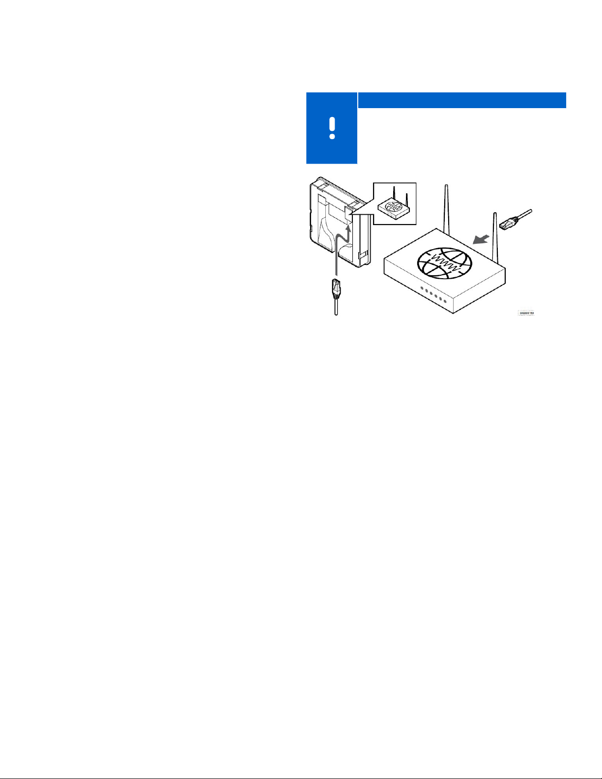
Chapter 11:
System Connectivity
The Smatrix Pulse system can connect to the Uponor
Cloud in standard home networks via the mobile app.
Due to security concerns, closed ports and firewalls will
prevent Smatrix Pulse systems from connecting to the
Uponor Cloud in office networks. Please review the list
of requirements for both router settings and network
requirements needed to successfully connect the Smatrix
Pulse system to the Uponor Cloud.
Smatrix Pulse Mobile App
Available for download from the App Store or Google Play,
the Smatrix Pulse App extends the flexibility and comfort of
an Uponor radiant system by adding remote access to its
range of possibilities.
Local access: When near the Communication Module
(R-208), the radiant system provides direct access.
There is no need for an Internet connection. However,
for maximum ease, the system can be accessed via the
Smatrix Pulse App.
Remote access: When away, the system can be accessed
via the Smatrix Pulse App or website on a smartphone,
tablet, or PC.
Router Requirements
• DHCP (IP address assignment) is activated in the router.
• Wi-Fi protected access is setup as WPA2-Personal or
WPA/WPA2-Personal.
• Wi-Fi connectivity is set at 802.11 b/g/n @2.4Ghz.
• MAC address is not blocked.
Note
The Communication Module can only
communicate with the Wi-Fi router at the 2.4 GHz
band. Make sure to connect to a SSID supporting
2.4 GHz or connect using an Ethernet cable. Mobile
hotspot 2.4GHz is supported.
Figure 11-1: Network requirements
• The system requires a minimum signal strength of -60
dBm. For typical connections, two bars will indicate a
signal strength in the -60 to -70 dBm range. However,
be aware that the signal may not be strong enough
for a stable connection. To get an exact dBm number
for signal strength, see the technical bulletin for more
information.
Network Requirements
• Open network without network security.
• SSID is distributed and not hidden.
• Repeaters are turned off during the Uponor Cloud
connection process, so the smartphone or tablet does
not connect to the repeaters.
• Wi-Fi repeaters should use the same SSID and password
of the main Wi-Fi.
• Once the user account is created and the system is
connected to the Uponor Cloud, the repeaters can be
switched on.
uponor.com l 41
Page 38
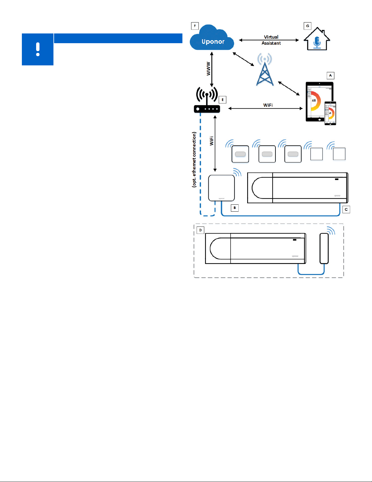
Network Connectivity
Note
Setting up a system with a Communication
Module requires a mobile device (smartphone/
tablet).
Set up and connect the Controller (C) using the Uponor
Smatrix Pulse App (A) and Communication Module (B) via
multiple connection methods.
Direct Connection (no Wi-Fi)
For installing and setting up a system and during normal
operation when there is no Wi-Fi network available,
the Uponor Smatrix Pulse App (A) communicates with
the room controller (C) via direct connection to the
Communication Module (B). The sub-Controller (D)
communicates via the Primary Controller (C).
Local Wi-Fi Connection
During normal operation when connected to the same
local Wi-Fi network, the Uponor Smatrix Pulse App (A)
communicates with the Controller (C) and the mobile
device connects to the same Wi-Fi router (E) as the
Communication Module (B). The Communication Module
(B) and Wi-Fi router (E) connect using either Wi-Fi or
Ethernet. The sub-Controller (D) communicates via the
Primary Controller (C).
Remote Connection (outside local Wi-Fi network)
During normal operation outside the local Wi-Fi network,
the Uponor Smatrix Pulse App (A) communicates with the
Controller (C) via a remote connection. The mobile device
connects to Uponor Cloud services (F) over internet (via
local Wi-Fi or mobile network). Uponor Cloud services (F)
connect to the Communication Module (B) via the WiFi router (E). The Communication Module (B) and Wi-Fi
router (E) are connected using either Wi-Fi or Ethernet.
The sub-Controller (D) communicates via the Primary
Controller (C).
Virtual Assistants (Amazon Alexa or Google Home)
Virtual assistants (G) communicate with the Controller
(C) via an Application Programming Interface (API) to
communicate with Uponor Cloud services (F). Uponor
cloud services (F) connect to the Communication Module
(B) via the Wi-Fi router (E). The Communication Module
(B) and Wi-Fi router (E) are connected using either Wi-Fi
or Ethernet. The sub-Controller (D) communicates via the
Primary Controller (C).
Figure 11-2: Network diagram
42 l Smatrix Pulse | Installation and Operation Manual
Page 39

Chapter 12:
Troubleshooting
This section covers general issues and alarms that can occur with the Smatrix Pulse system, along with the cause and
solutions. A common cause of a problem may be due to improperly installed loops or mixed up or incorrectly installed
thermostats.
Alarms
Issue Cause Resolution
Reoccurring alarms The antenna is installed inside a metal cabinet or
too close to other shielding objects.
The Communication Module is installed inside a
metal cabinet or too close to other shielding objects.
Building structure is unfavorable for radio
transmission.
Radio transmission error
icon is displayed in the
alarm list
Relative humidity icon is
displayed in the alarm list
Floor temperature sensor
icon is displayed in the
alarm list
Outdoor temperature
sensor icon is displayed in
the alarm list
Indoor temperature sensor
icon is displayed in the
alarm list
Remote temperature
sensor icon is displayed in
the alarm list
The transmitter is working with reduced signal
intensity.
The Antenna is installed inside a metal cabinet or
too close to other shielding objects.
The Communication Module is installed inside a
metal cabinet or too close to other shielding objects.
New installations in the building are shielding radio
signals (for example, a metal door safe).
The transmitter in the thermostat is faulty. • Force the thermostat to transmit by changing
The relative humidity limit is reached. • Lower the humidity level by increasing the
Incorrect thermostat control mode or temperature
sensor not connected.
There is a faulty temperature sensor. • Check the connection of the floor sensor.
Incorrect thermostat control mode or temperature
sensor not connected.
There is a faulty temperature sensor. • Check the connection of the outdoor sensor.
There is a faulty temperature sensor. • Contact the installer or replace the
Incorrect thermostat control mode or temperature
sensor not connected.
There is a faulty temperature sensor. • Check the connection of the remote sensor.
• Change the Antenna location.
• If the problem persists, contact the installer.
• Change the Communication Module location.
• If the problem persists, contact the installer.
• Change the Antenna location.
• If the problem persists, contact the installer.
• Force the thermostat to transmit by changing
the temperature setpoint.
• Replace the thermostat.
• Change the Antenna location.
• If the problem persists, contact the installer.
• Change the Communication Module location.
• If the problem persists, contact the installer.
• Try to find a new position for the thermostat
and/or the Antenna, or, if possible, move the
shielding object.
the temperature setpoint.
• Replace the thermostat.
ventilation or activating a dehumidifier.
• Select the correct thermostat control mode in
settings Menu 04.
• Disconnect the temperature sensor and check
it with an ohmmeter. Make sure the value
aligns with the temperature sensor diagram.
• Select the correct thermostat control mode in
settings Menu 04.
• Disconnect the temperature sensor and check
it with an ohmmeter. Make sure the value
aligns with the temperature sensor diagram.
thermostat.
• Select the correct thermostat control mode in
settings Menu 04.
• Disconnect the temperature sensor and check
it with an ohmmeter. Make sure the value
aligns with the temperature sensor diagram.
uponor.com l 43
Page 40
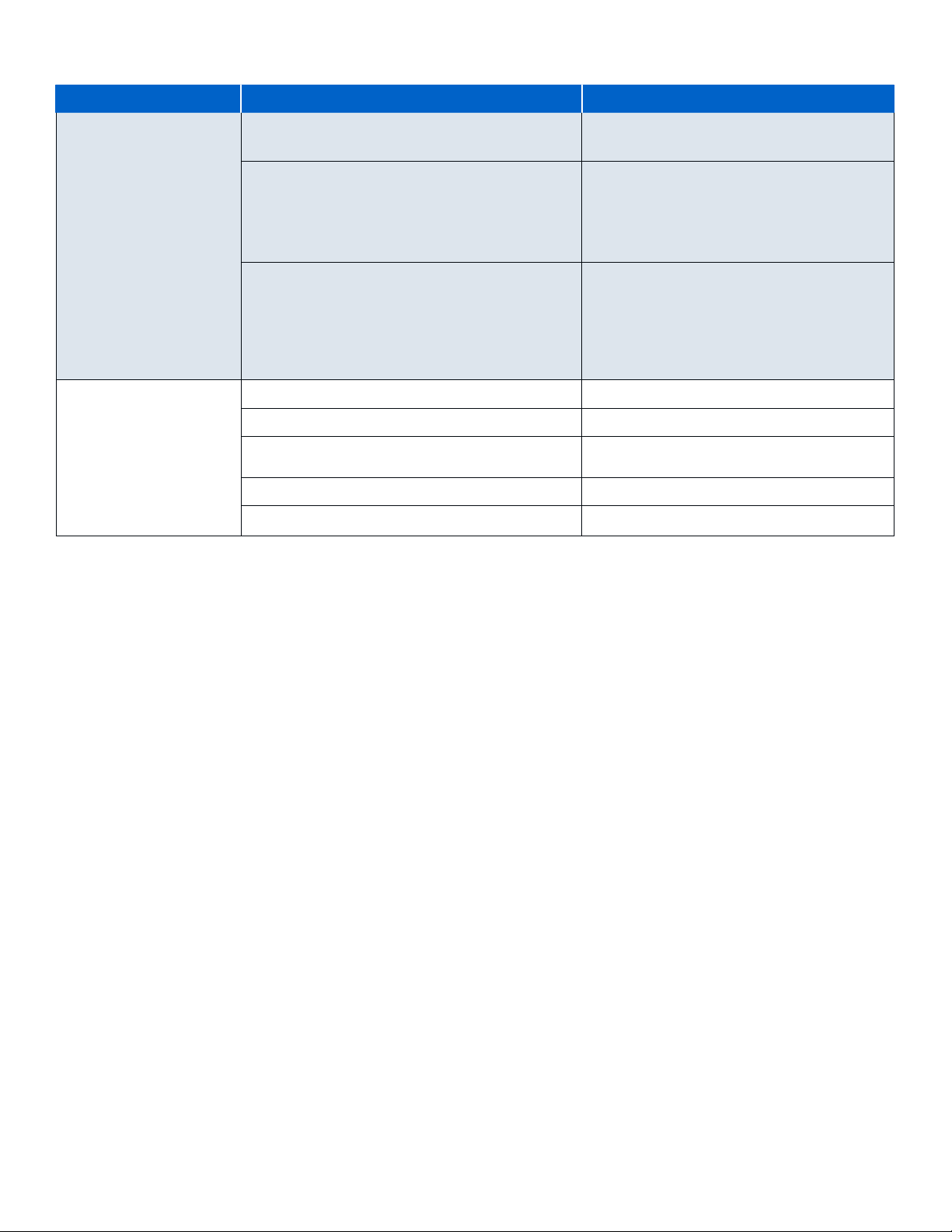
Cloud Connectivity
Issue Cause Resolution
Connection error during
setup
Communication error
connecting to the Uponor
Cloud
Important: For all
communication issues,
use the Help Wizard in
the Smatrix Pulse App to
restore the connection
Incorrect Wi-Fi password • Enter the correct password.
• If unknown, reset the router.
Poor signal strength • Check that the Communication Module is
mounted vertically.
• Verify the signal strength meets the minimum
requirements (< -60 dBM).
• Disconnect any repeaters.
Error creating user account • If user account already exists, login and add
the new installation.
• Verify the smartphone or tablet is connected
to the same network as the Communication
Module.
• Verify the network has internet access.
Internet locked down • Verify network requirements.
Wi-Fi password change • Enter the new password.
Router change • Change the Uponor Cloud connection in the
Smatrix Pulse App.
No power to the router • Restore power to the router.
No power to the Smatrix Pulse hardware • Restore power to the Smatrix Pulse hardware.
44 l Smatrix Pulse | Installation and Operation Manual
Page 41

Communication
Issue Cause Resolution
No communication or
receiving a communication
error
Thermostat lost The controller is having problems communicating
No floor temperature limit
settings available for the
room where the thermostat
is registered (Digital
Thermostat T-161 only)
Controller lost (primary) Communication failure with the controller. The
Registration is lost between devices. • Check the status of the Controller.
Controller software versions are incompatible. • Contact the installer.
The antenna is installed inside a metal cabinet
or too close to other materials that will shield
communication.
The thermostat or Relay Module is placed too far
from the Communication Module or antenna.
with the thermostat.
No floor temperature sensor is connected to the
thermostat.
More than one hour has passed between startup of
the thermostat and the sensor being inserted.
controller LED is flashing red.
• Contact the installer.
• Check the software versions of the controllers
using the Smatrix Pulse App.
• Change the Antenna location.
• If the problem persists, contact the installer.
• Change the location of the Communication
Module/Antenna, thermostat, thermostatic
head, and/or Relay Module.
• If the problem persists, contact the installer.
Force the thermostat to transmit by changing
the temperature setpoint.
If the problem persists:
• The thermostat is out of range. Try to find a
new position for the thermostat and/or the
Antenna, or, if possible, move any shielding
objects.
• New installations in the building are shielding
radio signals (for example, a metal door safe).
Try to find a new position for the thermostat
and/or the Antenna, or, if possible, move the
shielding object.
• Low radio signal detected (sporadic
communication with the connected unit).
The transmitter is working with reduced signal
intensity.
• The transmitter in the thermostat is faulty.
Replace the thermostat.
1. Connect the floor temperature sensor to
the thermostat.
2. Remove the battery from the thermostat.
3. Wait about 30 seconds.
4. Insert the battery again.
1. Remove the battery from the thermostat.
2. Wait about 30 seconds.
3. Insert the battery again.
• Make sure the controller is powered on.
• Make sure the cable between the
Communication Module and the Controller is
connected and not damaged.
• Restart the Controller if a factory reset of
the Communication Module was performed
(unplug and plug in the Controller from the
wall socket).
• If none of the above actions remedy the
situation, contact the installer.
uponor.com l 45
Page 42

Communication (continued)
Issue Cause Resolution
Controller lost (sub
controller)
Communication error with
Communication Module
Software update failed
The Communication
Module has lost
communication with
Uponor Cloud services.
Note: This alarm will only
be received as a push
notification and/or SMS
(if activated) to the mobile
phone number registered
to the customer account in
Uponor Cloud services.
Software update failed The Controller software update has failed. • Make sure all sub-Controllers are within radio
Relay Module lost Communication failure with the Relay Module. • Make sure the Relay Module is powered on.
Communication Module
does not power up
Bad Wi-Fi connection The Communication Module loses connection with
Communication failure with the controller. • Make sure the controller is powered on.
• Make sure the Antenna is connected to the
Controller and not damaged.
• Try registering the sub-Controller to the
Primary Controller again.
• If none of the above actions remedy the
situation, contact the installer.
There is a communication error with the
Communication Module. The controller LED is
flashing red.
There is a communication error between the
Communication Module and Uponor Cloud
services. The Communication Module LED is fixed
red, fixed orange, or flashing orange. Once the
communication between the Communication
Module and Uponor Cloud services is re-established,
the communication module LED is fixed green.
There is no power to the Communication Module. • Check the communication cable between the
the Wi-Fi network.
• Restart the Controller and Communication
Module (unplug and plug in the Controller
from the wall socket) and try again.
• Make sure the Communication Module is
connected to an internet-connected router,
via either Wi-Fi or Ethernet.
• Make sure the Communication Module is
connected to the Controller.
• Restart the router, if needed.
• Restart the Controller and Communication
Module, if needed (unplug and plug in the
Controller from the wall socket).
• Request help in the Smatrix Pulse App and
follow the wizard to determine the root cause.
range and not shielded by any object.
• Restart the Controller (power off and on
again).
• Contact the installer if the problem persists.
• Register the Relay Module again to the
Primary Controller.
• Contact the installer.
Controller and Communication Module. Make
sure it is connected properly.
• Replace the communication cable, if needed.
• Replace the Communication Module.
• Contact the installer.
• Connect the Communication Module to the
local network using an Ethernet cable.
• Refer to the Connect the Communication
Module section in Chapter 5: Installation for
information about connecting the Ethernet
cable.
46 l Smatrix Pulse | Installation and Operation Manual
Page 43

Controller
Issue Cause Resolution
Power indicator in the
controller is off
There is no power in the
115V wall outlet
Channel LEDs in the
controller continue flashing
Power LED and channel LED
on the Controller flashes
There is no AC power to the Controller. • Check that the Controller is connected to
AC power.
• Check the wiring in the 24V wiring
compartment.
• Check that there is 115V power at the wall
outlet.
A fuse is blown. • Reset the circuit breaker or replace the fuse.
• Correct the wiring issue.
There is faulty power supply or connections. • Replace the Transformer.
• Correct the wiring issue inside the 24V wiring
compartment.
The thermostat is not correctly positioned. • Check the placement of the thermostat so the
signal is not shielded by another object.
The Antenna is not correctly installed or positioned. • Check the wiring and Antenna connection.
• Make sure the Antenna is mounted in the
vertical position.
The Antenna is installed inside a metal cabinet or
too close to other shielding objects.
The Communication Module is installed inside a
metal cabinet or too close to other shielding objects.
The antenna is out of position, or a wire is
disconnected.
• Change the Antenna location.
• If the problem persists, contact the installer.
• Change the Communication Module location.
• If the problem persists, contact the installer.
• Install the Antenna in a correct position with
the cable correctly connected.
uponor.com l 47
Page 44

Room Temperature
Issue Cause Resolution
Floor temperature is
changing abnormally
between hot and cold in
heating mode
Room temperature does
not match setpoint on
thermostat and actuators
shut on/off on a fixed
interval
Room temperature does
not match setpoint on
thermostat
The room is too cold (or too
warm in cooling mode)
The temperature displayed
on the thermostat changes
after the thermostat is
moved
Installation report and
Controller/channel
numbering on the
thermostat label do not
match
All rooms are cold (or warm
in cooling mode)
Supply water temperature is too high. • Check the mixing control or boiler to verify the
temperature is set correctly.
• Run a supply diagnostic test from the Smatrix
Pulse App.
Heating Protection function is activated due to lost
communication with the thermostat.
The thermostat is placed in direct sunlight or close
to other heat sources.
The thermostat is placed in the wrong room.
Thermostat setpoint is too low. • Change the temperature setpoint.
The thermostat may be influenced by an external
heat source.
The thermostats of individual rooms are incorrectly
registered.
System is in ECO mode. • Reduce the ECO setback value for the
System is in the wrong operating mode. • Set the system to correct mode of operation
A mechanical device requires service. • Call the installer.
• Check thermostat(s) connections.
• Check batteries in the thermostat.
• Check the Smatrix Pulse App for a thermostat
communication error.
• Reconnect the lost thermostat.
• Check placement of the thermostat according
to installation instructions and change
location, if needed.
• Use maximum and minimum settings in the
Smatrix Pulse App to protect the system from
consequences of unreasonable temperature
settings.
Change the location of the thermostat.
Place the thermostat in the correct room or
change the thermostat registration in the
controller.
thermostat.
• Reduce the General ECO setback value in the
Smatrix Pulse App.
• Change the ECO profile or assign another
profile to the room.
• Cancel ECO mode and change to Comfort.
(heating or cooling).
• Check the boiler and/or pump operation.
48 l Smatrix Pulse | Installation and Operation Manual
Page 45

System
Issue Cause Resolution
Pump is turning on when
there is no demand
System not switching
between Comfort and ECO
mode
High supply temperature
(This alarm only displays
if Supply Diagnostics is
enabled in the Smatrix
Pulse App.)
Low supply temperature
(This alarm only displays
if Supply Diagnostics is
enabled in the Smatrix
Pulse App.)
Loop is warm even after an
extended period without
heat call
Low average temperature Thermostat setpoints are too low. • Increase the setpoints on the thermostats in
The system is running the pump in "Exercise" mode. • No action is required.
More than one Comfort/ECO switch is connected to
the system (to the GPI).
The supply temperature is too high. • Check the heat source or supply temperature
The supply temperature is too low. • Check the heat source or supply temperature
The actuator(s) are not closing. • Contact the installer.
The actuator(s) may still be in the initial factory
default position (partially open).
The supply temperature is too low. • Check the heat source or supply temperature
The average temperature limit is too low. • Increase the average temperature limit.
A window or door is open. • Close any windows or doors that might affect
• Select one GPI switch and uninstall the others
(only one switch in the system is supported).
controller to lower the supply temperature.
• Contact the installer if the problem persists.
controller to increase the supply temperature.
• Other potential causes may be too low flow on
the supply line or a malfunctioning circulation
pump.
• Contact the installer if the problem persists.
• Check that the actuator is installed correctly.
• Replace the actuator.
• Adjust setpoint temporarily to maximum
setting so the actuators fully open (channel
LED is red) to deactivate the default position.
• Manually cycle the actuator.
the rooms where the average temperature is
calculated.
controller to increase the supply temperature.
• Other possible causes may be too low flow on
the supply line or a malfunctioning circulation
pump.
• Contact the installer if the problem persists.
the measured temperature.
uponor.com l 49
Page 46

Thermostat
Issue Cause Resolution
Setpoint temperature
displayed in the room
information menu is lower
than the temperature set
on the thermostat
The display for the Digital
Thermostat (T-169) is not
showing any information
The LED on the Mini Sensor
(T-161) flashes every two
hours, or low battery alarm
displayed in the Smatrix
Pulse App
Thermostat battery level
low
Low radio signal detected
(sporadic communication
with the connected unit)
Faulty temperature sensor An error has been detected with the internal
Faulty external temperature
sensor
Faulty relative humidity
sensor
Relative humidity sensor
limit
Incorrect minimum/maximum limitation • Change the minimum/maximum limitation in
The battery is discharged, or the wrong type of
battery is used.
The battery is installed incorrectly (reverse polarity). • Install the battery correctly.
Thermostat battery power is running low. • Replace the battery.
The thermostat battery power is running low. • Replace the battery.
The thermostat is out of range. • Force the thermostat to transmit by changing
New installations in building shield radio signals (for
example, a metal door safe).
The transmitter is working with reduced signal
intensity.
The transmitter in the thermostat faulty. • Replace the thermostat.
temperature sensor in the thermostat
An error has been detected with the external sensor
connected to the thermostat.
An error has been detected with the internal relative
humidity sensor in the thermostat.
The relative humidity limit is reached. • Lower the humidity level by starting a
the Smatrix Pulse App.
• Replace the battery (CR 2023V).
the temperature setpoint.
• Try to find a new position for the thermostat
and/or the Antenna, or, if possible, move the
shielding object
• Replace the thermostat.
• Replace the thermostat.
• Make sure the correct thermostat control
mode in settings Menu 04 is set in the Digital
Thermostat (T-169).
• Check the connection of the external sensor.
• Disconnect the external sensor and check it
with an ohmmeter. Make sure the value aligns
with the temperature sensor diagram.
• If the error persists, replace the external
sensor.
• Replace the thermostat.
dehumidifier or increasing the supply
temperature setpoint.
50 l Smatrix Pulse | Installation and Operation Manual
Page 47

Chapter 13:
Technical Data
Thermostats
Part numbers A3800169 Digital Thermostat (T-169)
A3800161 Mini Sensor (T-161)
IP IP20, Class III (IP: degree of inaccessibility to active parts of the
product and degree of water)
Maximum ambient RH (relative humidity) 85% at 68°F (20°C)
ERP IV
Low voltage tests EN 60730-1* and EN 60730-2-9***
EMC (electromagnetic compatibility requirements) tests EN 60730-1 and EN 301-489-3
ERM (electromagnetic compatibility and radio spectrum
matters) tests
Power supply 1 x CR2032 3V
Voltage 2.4 V to 3.6 V
Rated impulse voltage 0.33 kV, OVC I
Pollution degree 2
Software class A
Operating temperature 32°F to 113°F
Storage temperature 14°F to 149°F
Radio frequency 912.0 MHz
Transmitter duty cycle <1%
Connection terminals 18 - 24 AWG
EN 300 220-3
(0°C to 45°C)
(-10°C to 65°C)
uponor.com l 51
Page 48

Relay Module
Part number A3801263 Relay Module (M-263)
IP IP20, Class II (IP: degree of inaccessibility to active parts of the
product and degree of water)
Maximum ambient RH (relative humidity) 85% at 68°F (20°C)
ERP IV
Low voltage tests EN 60730-1* and EN 60730-2-1**
EMC (electromagnetic compatibility requirements) tests EN 60730-1 and EN 301-489-3
ERM (electromagnetic compatibility and radio spectrum
matters) tests
Power supply 24VAC +10/-15%, 50 Hz or 60 Hz
Pollution degree 2
Software class A
Operating temperature 32°F to 122°F
Storage temperature -4°F to 158°F
Radio frequency 912.0 MHz
Transmitter duty cycle <1%
Relay outputs 24VAC +10/-15%, 2.5 A maximum
Power connection 16" XM flexible cord connected to the Relay Module
Connection terminals 18 - 24 AWG
Antenna
Part number A3800265 Antenna (A-265) (replacement part)
IP IP20, Class III (IP: degree of inaccessibility to active parts of the
Maximum ambient RH (relative humidity) 85% at 68°F (20°C)
EN 300 220-3
(0°C to 50°C)
(-20°C to 70°C)
Micro gap, normally open
product and degree of water)
Power supply From Controller
Radio frequency 912.0 MHz
Transmitter duty cycle <1%
Receiver class 2
52 l Smatrix Pulse | Installation and Operation Manual
Page 49

Communication Module
Part number A3801208 Communication Module (R-208) (replacement part)
IP IP20, Class III (IP: degree of inaccessibility to active parts of the
product and degree of water)
Maximum ambient RH (relative humidity) 85% at 68°F (20°C)
Low voltage tests EN 60730-1* and EN 60730-2-9***
EMC (electromagnetic compatibility requirements) tests EN 60730-1 and EN 301-489-3
ERM (electromagnetic compatibility and radio spectrum
matters) tests
Power supply From Controller
EN 300 220-3
uponor.com l 53
Page 50

Controllers
Part number A360265A Controller (X-265) with Antenna (A-265)
A360265C Controller (X-265) with Communication Module
R-208)
IP IP20, Class II (IP: degree of inaccessibility to active parts of the
product and degree of water)
Maximum ambient RH (relative humidity) 85% at 68°F (20°C)
Low voltage tests EN 60730-1* and EN 60730-2-9***
EMC (electromagnetic compatibility requirements) tests EN 60730-1 and EN 301-489-3
ERM (electromagnetic compatibility and radio spectrum
EN 300 220-3
matters) tests
Power supply 115 VAC +10/-15%, 50 Hz or 60 Hz
Internal fuse T5 F3.15AL 250 V, 5x20 3.15A quick acting
Rated impulse voltage 2.5 kV, OVC II
Pollution degree 2 2
Software class A A
Operating temperature 0°C to +45°C 32°F to 113°F
(0°C to 45°C)
Storage temperature -20°C to +70°C -4°F to 158°F
(-20°C to 70°C)
Maximum consumption 45 W
Pump and boiler relay outputs 24 VAC +10/-15%, 8 A maximum
Micro gap, normally open
General purpose input (GPI) Only dry contact
Valve outputs 24 VAC, 0.2 A average, 0.4 A peak
Power connection XM flexible cord with plug, which is connected to the controller
Connection terminals for pump, GPI, and boiler 18 - 24 AWG
Connection terminals for valve outputs 18 - 24 AWG
* EN 60730-1 Automatic electrical controls for household and similar use -- Part 1: General requirements
** EN 60730-2-1 Automatic electrical controls for household and similar use -- Part 2-1: Particular requirements for electrical controls for electrical
household appliances
*** EN 60730-2-9 Automatic electrical controls for household and similar use -- Part 2-9: Particular requirements for temperature sensing controls
54 l Smatrix Pulse | Installation and Operation Manual
Page 51
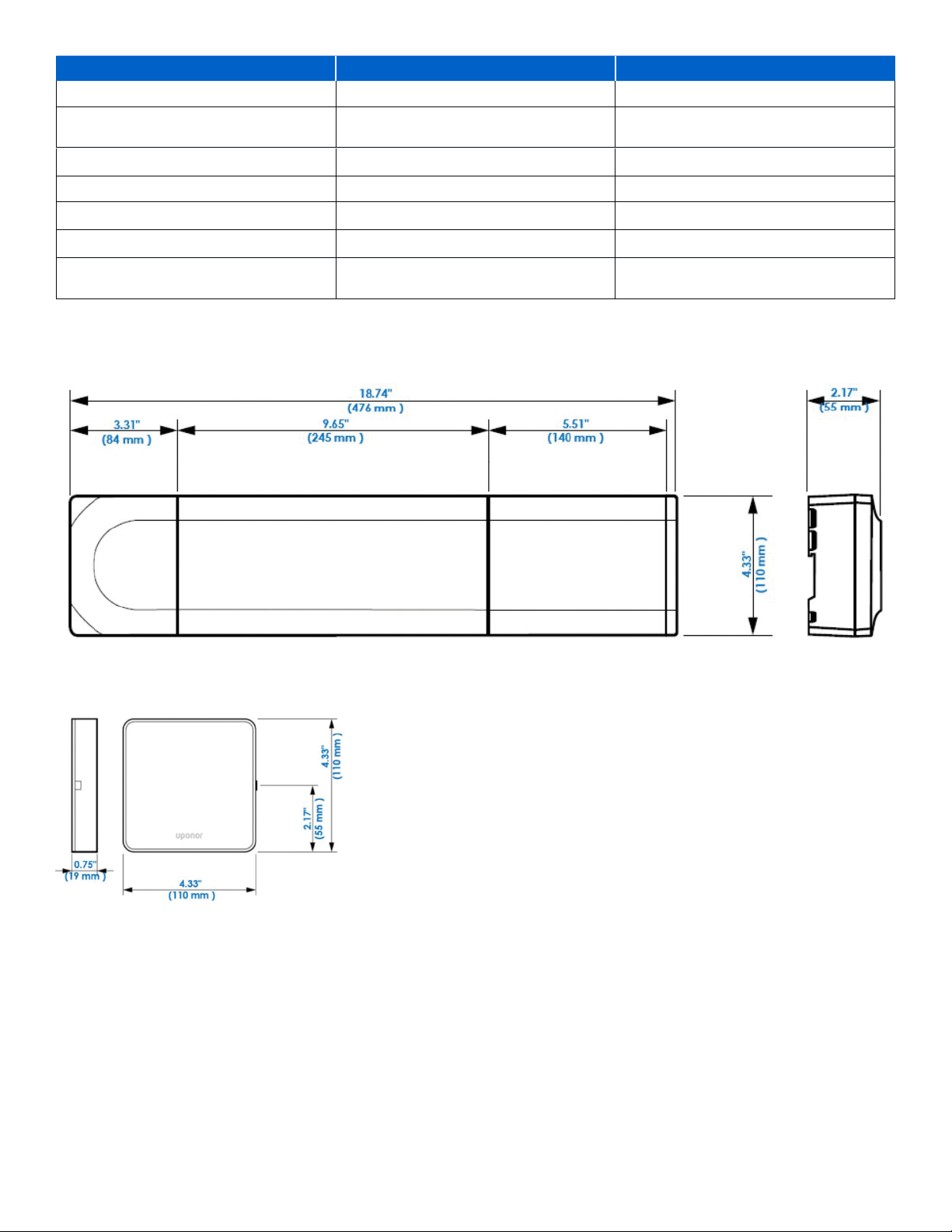
Cables Maximum Length Wire Gauge/Type
Cable from Controller to antenna 16.4' (5 m) CAT5e or CAT6, RJ 45 connector
Cable from Controller to Communication
Module
Cable from Controller to actuator 65' (20 m) 18 - 24 AWG
External sensor cable to thermostat 16.4' (5 m) 18 - 24 AWG
Floor sensor cable to thermostat 16.4' (5 m) 18 - 24 AWG
Outdoor sensor cable to thermostat 16.4' (5 m) 18 - 24 AWG, twisted pair
16.4' (5 m) CAT5e or CAT6, RJ 45 connector
Cable from relay switch to Controller GPI
input
Product Dimensions
Controller (X-265)
Figure 13-1: Controller (X-265)
Communication Module (R-208)
65' (20 m) 18 - 24 AWG
Figure 13-2: Communication Module (R-208)
uponor.com l 55
Page 52
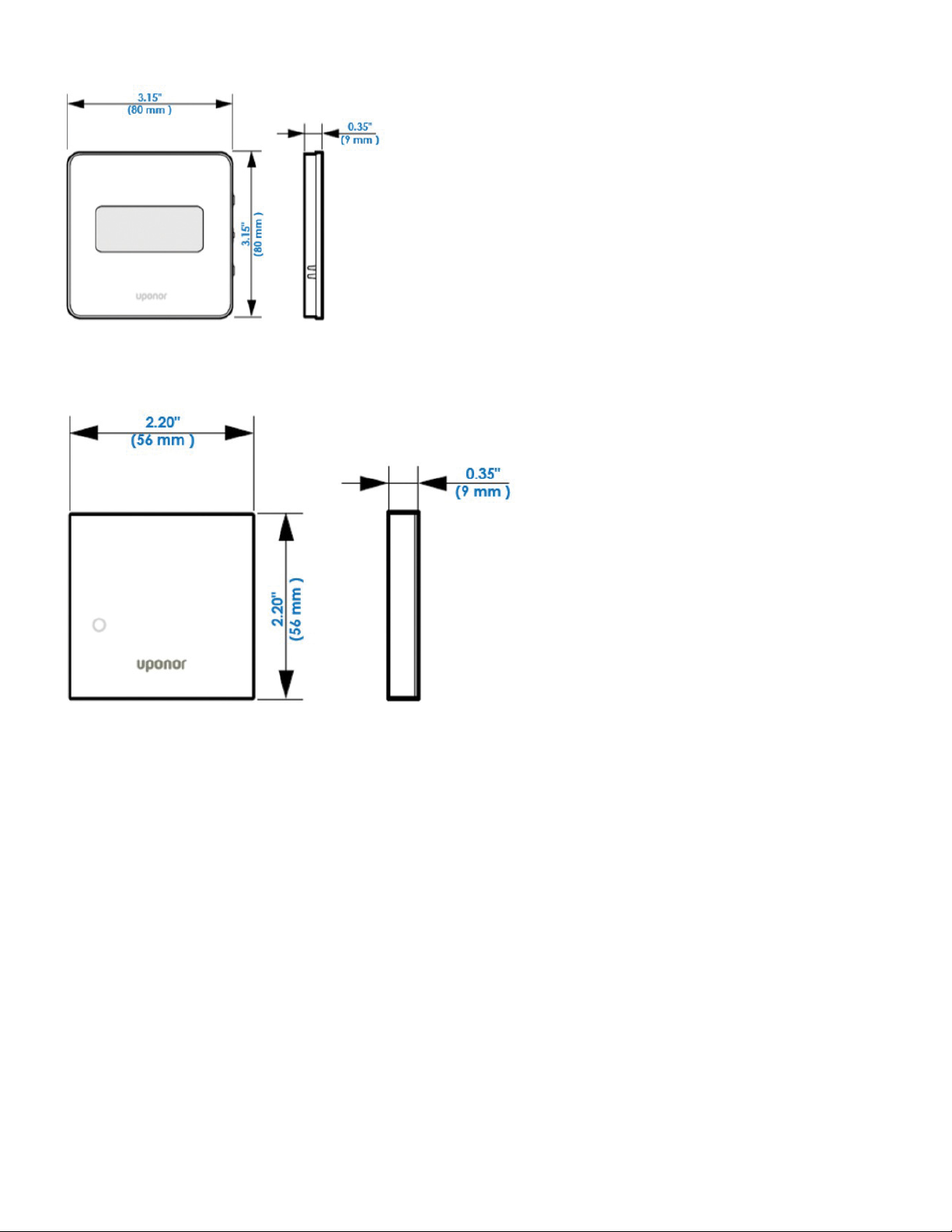
Digital Thermostat (T-169)
Figure 13-3: Digital Thermostat (T-169)
Mini Sensor (T-161)
Figure 13-4: Mini Sensor (T-161)
56 l Smatrix Pulse | Installation and Operation Manual
Page 53

Temperature vs. Resistance
Temperature Resistance
°F °C Ω
-50 -46 490,813
-45 -43 405,710
-40 -40 336,606
-35 -37 280,279
-30 -34 234,196
-25 -32 196,358
-20 -29 165,180
-15 -26 139,402
-10 -23 118,018
-5 -21 100,221
0 -18 85,362
5 -15 72,918
10 -12 62,465
15 -9 53,658
20 -7 46,218
25 -4 39,913
30 -1 34,558
35 2 29,996
40 4 26,099
45 7 22,763
50 10 19,900
55 13 17,436
60 16 15,311
65 18 13,474
70 21 11,883
75 24 10,501
80 27 9,299
85 29 8,250
Temperature Resistance
°F °C Ω
90 32 7,334
95 35 6,532
100 36 5,828
105 41 5,210
110 43 4,665
115 46 4,184
120 49 3,760
125 52 3,383
130 54 3,050
135 57 2,754
140 60 2,490
145 63 2,255
150 66 2,045
155 68 1,857
160 71 1,689
165 74 1,538
170 77 1,403
175 79 1,281
180 82 1,172
185 85 1,073
190 88 983
195 91 903
200 93 829
205 96 763
210 99 703
215 102 648
220 104 598
225 107 553
uponor.com l 57
Page 54

Notes
58 l Smatrix Pulse | Installation and Operation Manual
Page 55

Notes
uponor.com l 59
Page 56

Uponor Inc.
5925 148th Street West
Apple Valley, MN 55124
USA
Uponor Ltd.
6510 Kennedy Road
Mississauga, ON L5T 2X4
CANADA
T 800.321.4739
F 952.891.2008
T 888.594.7726
F 800.638.9517
uponor.com
SmatrixPulse_manual_0323, Copyright © 2023 Uponor. Printed in the United States.
 Loading...