

Page 1

Single-zone snow
melt control
installation and
operation manual
The Uponor Single-zone Snow Melt Control
(A3040654) is designed to operate hydronic
equipment to melt snow or ice from any
surface including driveways, walkways,
patios, business entrances, parking ramps,
loading docks, hospital entrances, helipads
or car wash bays.
The surface temperature for snow melting
is controlled automatically to reduce
operating energy costs. The control has
an automatic start and stop function when
used with the Pavement Snow and Ice
Sensor (A3040090).
Automatic start with a timed stop is
available when used with the Aerial
Snow Sensor (A3040095). The control
can operate a dedicated hydronic boiler.
Isolation relays are required to operate
line voltage pumps.
Features
• Automatic snow/ice detection
• Supports both in-slab and retrot aerial
snow sensors
• Mixing with modulating boiler
• Manual start with timer
• Warm weather shut down
• Cold weather cut out
• Idling
• Slab protection
• EconoMelt
• Manual override
• Exercising
• Alert output
Page 2
2 | uponorpro.com
Important safety information
Warning
It is your responsibility to ensure that this control is safely installed according to all applicable codes
and standards. Uponor is not responsible for damages resulting from improper installation and/or
maintenance.
Radio frequency interference
The installer must ensure this control and its wiring
are isolated and/or shielded from strong sources of
electromagnetic noise. Conversely, this Class B digital
apparatus complies with Part 15 of the FCC Rules and
meets all requirements of the Canadian InterferenceCausing Equipment Regulations. However, if this
control causes harmful interference to radio or television
reception, (determined by turning the control off and
on) try to correct the interference by re-orientating or
relocating the receiving antenna, relocating the receiver
with respect to this control, and/or connecting the control
to a different circuit connected to the receiver.
Single-zone snow melt control installation and operation manual is published by
Uponor Inc.
5925 148th Street West
Apple Valley, MN 55124
USA
T 800.321.4739
F 952.891.2008
uponorpro.com
© 2017 Uponor. All rights reserved.
Second Edition
Second printing August 2017
Printed in Canada
Uponor Ltd.
6510 Kennedy Road
Mississauga, ON L5T 2X4
CANADA
T 888.994.7726
F 800.638.9517
uponorpro.com
Uponor has used reasonable efforts in collecting, preparing and
providing quality information and material in this manual. However,
system enhancements may result in modication of features or
specications without notice. Uponor is not liable for installation
practices that deviate from this manual or are not acceptable
practices within the mechanical trades.
To avoid serious personal injury and damage to the equipment:
• Read manual and all product labels before
using the equipment. Do not use unless
you know the safe and proper operation
of this equipment.
• Keep this manual available for easy access
by all users. Replacement manuals are
available at uponorpro.com.
• Disconnect all power before opening
the control.
• Safely install this control according to all
applicable codes and standards. Improper
installation and operation of this control
could result in damage to the equipment
and possibly even personal injury or death.
• Only place controls that are intended and
certied as safety limits into the control
circuit. This electronic control is not intended
for use as a primary limit control.
• Do not attempt to service the control. There
are no user serviceable parts inside the control.
Attempting to do so voids the warranty.
Page 3

Single-zone snow melt control installation and operation manual | 3
Table of contents
Important safety information ................. 2
Installation .............................................. 4
Preparation ............................................. 4
Physical dimensions ............................... 4
Installation location ................................. 4
Rough-in wiring ...................................... 4
Sizing the transformer ........................... 5
Control wiring ........................................ 5
Sensor wiring ........................................ 7
Testing the sensor wiring ....................... 9
Testing the control wiring ....................... 9
Manual override — maximum heat ........ 10
Manual override — test .......................... 10
Manual override — purge ..................... 10
Manual override — off .......................... 11
Switch settings ....................................... 11
User interface ......................................... 12
Display .................................................... 12
Operation eld ........................................ 12
Status eld.............................................. 12
Symbols .................................................. 12
Programmable settings .......................... 13
Programming menus .............................. 13
Access levels and access level lock ...... 14
View menu ............................................. 14
Set Temp menu ..................................... 16
Monitor menu ......................................... 17
Display menu ......................................... 18
Toolbox menu ........................................ 18
Override menu ....................................... 19
System menu ......................................... 20
Boiler menu ............................................ 21
Sequence of operation ........................... 22
Snow melting overview .......................... 22
Slab temperature control ........................ 22
Melt operation ........................................ 22
Manual start and timed stop .................. 23
Automatic start and stop ....................... 23
Automatic start and timed stop .............. 24
EconoMelt .............................................. 24
Additional melting time ........................... 25
Idle operation ........................................ 25
Warm weather shut down ...................... 26
Cold weather cut out ............................. 26
Away key ................................................ 27
Slab protection ....................................... 27
Application modes .................................. 27
Electric operation ................................... 28
Pulse width modulation operation .......... 28
Boiler operation ...................................... 28
Exercising ............................................... 30
Alert relay ............................................... 30
Pump post purge .................................... 30
Troubleshooting...................................... 30
Error messages ...................................... 30
Symptoms and solutions ........................ 32
Job record .............................................. 33
Technical data ....................................... 34
Getting started
Congratulations on the purchase of your new Uponor Single-zone Snow Melt Control.
This manual covers installation, programming, sequence of operation, instruction on
testing, commissioning and troubleshooting.
Page 4

4 | uponorpro.com
Installation
Preparation
Tools required
• Jeweller screwdriver
• Phillips head screwdriver
• Needle-nose pliers
• Wire stripper
Materials required
• 18 AWG LVT solid wire
(low-voltage connections)
• 24 VAC transformer
Physical dimensions
Installation location
When choosing the location for
the control, consider the following:
• Interior wall
• Keep dry; avoid potential leakage onto
the control
• Relative humidity less than 90%;
non-condensing environment
• No exposure to temperatures below -4ºF
(-20ºC) or above 122ºF (50ºC)
• No draft, direct sun or other cause for
inaccurate temperature readings
• Away from equipment, appliances or other
sources of electrical interference
• Easy access for wiring, viewing
and adjusting the display screen
• Maximum wire length of 500 feet (150m)
• Approximately 5 feet (1.5m) off the
nished oor
• Strip wire to ⅜" (10mm) for all terminal
connections
• Use standard 8-conductor, 18 AWG wire
Rough-in wiring
Low-voltage wiring
Pull each cable from the equipment to the
control’s plastic enclosure. All low-voltage
wiring connections enter the enclosure
through the square knockout on the rear.
Uponor recommends labeling each cable
for easy identication. Strip all low-voltage
wires to a length of ⅜" (9mm) to ensure
proper connection to the control.
Front view
5"
Side view Mounting base
Brn
slab
Mod
+
Aux Ht R C
-
Out
Blk
com
Yel Blu Red Sup
No power
CL
CL
CL
3¼"
(82mm)
15
⁄16"
(23mm)
13
⁄16"
(20mm)
29
⁄32"
(23mm)
1½"
(38mm)
4"
(102mm)
9
⁄16"
(14mm)
1⅞"
(47mm)
2½"
(64mm)
¾"
(19mm)
3¼"
(83mm)
Page 5

Single-zone snow melt control installation and operation manual | 5
Pull 4-conductor, 18 AWG LVT cable up to
500 feet (150m) for the Aerial Snow Sensor
(A3040095).
Pull 5-conductor, 18 AWG LVT cable up to
500 feet (150m) for the Pavement Snow
and Ice Sensor (A3040090).
Pull 2-conductor, 18 AWG LVT cable up to
500 feet (150m) for the following equipment:
• 24 VAC power from transformer
• Outdoor temperature sensor
• Supply sensor (if applicable)
• On/off boiler (if applicable)
• Modulating boiler 0-10 VDC or 4-20 mA
(if applicable)
• Alert output (if applicable)
Sizing the transformer
The control requires an external transformer.
The total power capacity of the power supply
should be larger than the total load of all the
devices connected to the control. This total
load must not exceed 100 VA.
Control wiring
Pavement Snow and
Ice Sensor (A3040090)
Aerial Snow Sensor
(A3040095)
Slab Sensor
for Aerial
Snow Sensor
(A3040073)
Snow
Sensor
095
Pavement Snow and Ice Sensor (A3040090)
Outdoor and supply sensors Modulating boiler output
Aerial Snow Sensor (A3040095) and Slab Sensor
for Aerial Snow Sensor (A3040073)
Outdoor
sensor
Supply
sensor
– +
Modulating boiler
Brn
slab
Mod
+
Aux Ht R C
-
Out
Blk
com
Yel Blu Red Sup
No power
Brn
slab
Mod
+
Aux Ht R C
-
Out
Blk
com
Yel Blu Red Sup
No power
Brn
slab
Mod
+
Aux Ht R C
-
Out
Blk
com
Yel Blu Red Sup
No power
Brn
slab
Mod
+
Aux Ht R C
-
Out
Blk
com
Yel Blu Red Sup
No power
Page 6

6 | uponorpro.com
Control wiring
Alert relay output
Alert
equipment
Brn
slab
Mod
+
Aux Ht R C
-
Out
Blk
com
Yel Blu Red Sup
No power
Transformer and relays
Alert
equipment
24 VAC relay 24 VAC relay
System
pump
2
1
8
7
3
4
5
6
2
1
8
7
3
4
5
6
Transformer
L
N
C
R
On/off boiler
TT
LNG
115 VAC
Brn
slab
Mod
+
Aux Ht R C
-
Out
Blk
com
Yel Blu Red Sup
No power
Brn
slab
Mod
+
Aux Ht R C
-
Out
Blk
com
Yel Blu Red Sup
No power
Brn
slab
Mod
+
tN4
-
Out/
bret
Blk
com
Yel Blu Red Sup
No power
Page 7

Single-zone snow melt control installation and operation manual | 7
Wiring the outdoor sensor
Wires from
outdoor sensor to
controlʼs outdoor
sensor and sensor
common terminals
Sensor is built into
the enclosure
Sensor wiring
Mounting the outdoor sensor
Note: The temperature sensor (thermistor)
is built into the sensor enclosure.
• Remove the screw and pull the front cover
off the sensor enclosure.
• Mount the outdoor sensor directly onto a
wall or a 2" x 4" electrical box. When wall
mounting the outdoor sensor, the wiring
should enter through the back or bottom of
the enclosure. Do not mount the outdoor
sensor with the conduit knockout facing
upward as rain could enter the enclosure
and damage the sensor.
• To prevent heat through the wall from
affecting the sensor reading, it may be
necessary to install an insulating barrier
behind the enclosure.
• Mount the outdoor sensor on a wall
which best represents the heat load
on the building (a northern wall for most
buildings and a southern-facing wall for
buildings with large south-facing glass
areas). Do not expose the outdoor sensor
to heat sources such as ventilation or
window openings.
• Install the outdoor sensor at an elevation
above the ground that will prevent
accidental damage or tampering.
Wiring the outdoor sensor
• Connect 18 AWG or similar wire to the two
terminals provided in the enclosure and
run the wires from the outdoor sensor to
the control. Do not run the wires parallel to
telephone or power cables. If the sensor
wires are located in an area with strong
sources of electromagnetic interference
(EMI), use shielded cable or twisted pair or
run the wires in a grounded metal conduit.
If using shielded cable, connect the shield
wire to the Com or Com Sen terminal on
the control and not to earth ground.
• Follow the sensor testing instructions
in this manual and connect the wires
to the control.
• Replace the front cover of the
sensor enclosure.
Sensor with
bottom-entry wiring
Sensor with
rear-entry wiring
Sensor mounted
onto 2" x 4"
electrical box
Mounting the outdoor sensor
Page 8

8 | uponorpro.com
Strapping to pipe
Strap the sensor directly to the pipe using
the cable tie provided. Place insulation
around the sensor to reduce the effect of
air currents on the sensor measurement.
Immersion well
If mounting a sensor onto 1" (25mm)
diameter, Type L copper pipe, there is
approximately an 8-second delay between
a sudden change in water temperature
and the time the sensor measures the
temperature change. This delay increases
considerably when using mild steel
(black iron) pipe. Uponor recommends
using a temperature well for steel pipe
of diameter greater than 1¼" (32mm).
Uponor also recommends temperature
wells when using large-diameter pipes
and uid stratication is present.
Sensor mounted
onto 2" x 4"
electrical box
Wires from outdoor
sensor to control’s
outdoor sensor
and sensor
common terminals
Sensor is built into
the enclosure
Mounting the sensor
Sensor
Cable tie
Sensor well
Retaining
clip
Sensor
Bottom of
enclosure
Mounting the slab sensor
Note: The Slab Sensor for Aerial Snow
Sensor (A3040073) can mount on a pipe
or in a temperature immersion well.
Place the sensor downstream of a pump
or after an elbow or similar tting. This is
especially important if the system uses
large-diameter pipes, as the thermal
stratication within the pipes can result in
erroneous sensor readings. Proper sensor
location requires the uid is thoroughly
mixed within the pipe before it reaches
the sensor.
Page 9

Single-zone snow melt control installation and operation manual | 9
Conduit connection
The slab sensor and slab sensor
enclosure (sold separately) are specically
designed to mount onto a ⅜" (10mm) I.D.
temperature well that is supplied with an
end groove. To install the well, plumb a ‘T’
into the pipe and x the well into the ‘T’.
Remove the ⅞" (22mm) back knockout to
place the enclosure over the temperature
well. Then insert the universal sensor
into the well and snap the retaining clip
supplied with the enclosure onto the well
end groove. If the well has a threaded end,
add a standard threaded conduit retaining
ring. The two wires from the sensor are
connected to the terminal block provided
in the enclosure. The other side of the
terminal block is used to connect wires
from the control.
Testing the sensor wiring
A good-quality test meter capable of
measuring up to 5,000 kΩ (1 kΩ = 1000
Ω) is required to measure the sensor
resistance. In addition to this, the actual
temperature must be measured with either
a good quality digital thermometer, or if
a thermometer is not available, a second
sensor can be placed alongside the one to
be tested and the readings compared.
First measure the temperature using
the thermometer and then measure the
resistance of the sensor at the control. The
wires from the sensor must not be connected
to the control while the test is performed.
Using the chart below, estimate the
temperature measured by the sensor. The
sensor and thermometer readings should
be close. If the test meter reads a very high
resistance, there may be a broken wire, a
poor wiring connection or a defective sensor.
If the resistance is very low, the wiring may
be shorted, there may be moisture in the
sensor or the sensor may be defective. To
test for a defective sensor, measure the
resistance directly at the sensor location.
Testing the control wiring
Testing the power
1. Remove the front cover from
the control.
2. Use an electrical test meter to
measure AC voltage between the
R and C terminals. The reading
should be 24 VAC +/– 10%.
3. Install the front cover.
Temp. Resistance Temp. Resistance Temp. Resistance Temp. Resistance
ºF ºC Ω ºF ºC Ω ºF ºC Ω ºF ºC Ω
-50 -46 490,813 20 -7 46,218 90 32 7,334 160 71 1,689
-45 -43 405,710 25 -4 39,913 95 35 6,532 165 74 1,538
-40 -40 336,606 30 -1 34,558 100 38 5,828 170 77 1,403
-35 -37 280,279 35 2 29,996 105 41 5,210 175 79 1,281
-30 -34 234,196 40 4 26,099 110 43 4,665 180 82 1,172
-25 -32 196,358 45 7 22,763 115 46 4,184 185 85 1,073
-20 -29 165,180 50 10 19,900 120 49 3,760 190 88 983
-15 -26 139,403 55 13 17,436 125 52 3,383 195 91 903
-10 -23 118,018 60 16 15,311 130 54 3,050 200 93 829
-5 -21 100,221 65 18 13,474 135 57 2,754 205 96 763
0 -18 85,362 70 21 11,883 140 60 2,490 210 99 703
5 -15 72,918 75 24 10,501 145 63 2,255 215 102 648
10 -12 62,465 80 27 9,299 150 66 2,045 220 104 598
15 -9 53,658 85 29 8,250 155 68 1,857 225 107 553
Do not apply voltage to a
sensor at any time as damage
to the sensor may result.
Page 10

10 | uponorpro.com
Testing the relay outputs
The control includes an Override menu to
check if the control’s relays are operating
and that the control is wired correctly to the
snow melting equipment.
1. Press and hold the Home button for
3 seconds.
2. Press NEXT to navigate to the Override
menu.
3. Press ENTER to enter the Override
menu.
4. Select Manual Override to Hand.
5. For hydronic systems, set System Pump
to On. The system pump should now be
operating.
6. Set Heat Relay to On. The boiler or
electric heating cables should start
heating.
7. For modulating boilers, change the Boiler
Percent from 0 to 100%. The boiler
should be ring.
8. Select the Override Time after which the
control resumes normal operation.
9. Exit the Manual Override by selecting
Auto.
Manual override —
maximum heat
In hydronic application modes, the control
includes a Maximum Heat operation where
the control operates the snow melting
system to maintain the maximum allowed
heating setpoints. This allows testing of the
snow melting system during warm weather.
1. Press and hold the Home button for
3 seconds.
2. Press NEXT to navigate to the Override
menu.
3. Press ENTER to enter the Override
menu.
4. Select Manual Override to Max.
5. Select the Maximum Heat Time after
which the control resumes normal
operation.
6. Exit the Manual Override by selecting
Auto.
Manual override — test
When operating an electric snow melting
system, the control includes a Test
operation where the electrical heating
cables can be energized for 10 minutes
after which the control resumes normal
operation. This allows testing of the electric
snow melting system during warm weather.
1. Press and hold the Home button for
3 seconds.
2. Press NEXT to navigate to the Override
menu.
3. Press ENTER to enter the Override
menu.
4. Select Manual Override to Test.
5. Exit the Manual Override by selecting
Auto.
Manual override — purge
When operating a hydronic snow melting
system, it is necessary to purge and
bleed all air out of the system. The control
includes a Purge operation where the
System Pump is turned on to assist in
purging air from the system.
1. Press and hold the Home button for
3 seconds.
2. Press NEXT to navigate to the
Override menu.
3. Press ENTER to enter the
Override menu.
4. Select Manual Override to Purge.
5. Select the Maximum Purge Time
after which the control resumes
normal operation.
6. Exit the Manual Override by
selecting Auto.
Page 11

Single-zone snow melt control installation and operation manual | 11
Switch settings
Back of control
Power: 24 V (ac) ±10%, 60 Hz, Class 2,
16 VA standby, 100 VA fully loaded
Relays: 24 V (ac) 2 A, 3.5 A combined
1058-05
Switch
settings
Designed and assembled in Canada
Meets Class B: ICES & FCC Part 15
Lock
Unused
Unlock
ON
1
2
HxxxxA
Single-zone
Snow Melt Control
Switch Position Action
1
ON
Lock access level – The control
is locally locked and the access
level cannot be changed. Set to
Lock when installation has been
completed.
OFF
Unlock access level – The
control is unlocked and the
access level may be changed. Go
to the Toolbox menu to change
the access level. Set to Unlock
during the installation process.
2
ON Not used
OFF Not used
Manual override — off
The snow melting system can be manually
turned off and the control remains off until
manually changed back to Auto. This allows
the installer or end user to permanently
disable the snow melting system without
removing power from the control.
1. Press and hold the Home button for
3 seconds.
2. Press NEXT to navigate to the Override
menu.
3. Press ENTER to enter the Override
menu.
4. Select Manual Override to Off.
5. Exit the Manual Override by selecting
Auto.
Page 12
12 | uponorpro.com
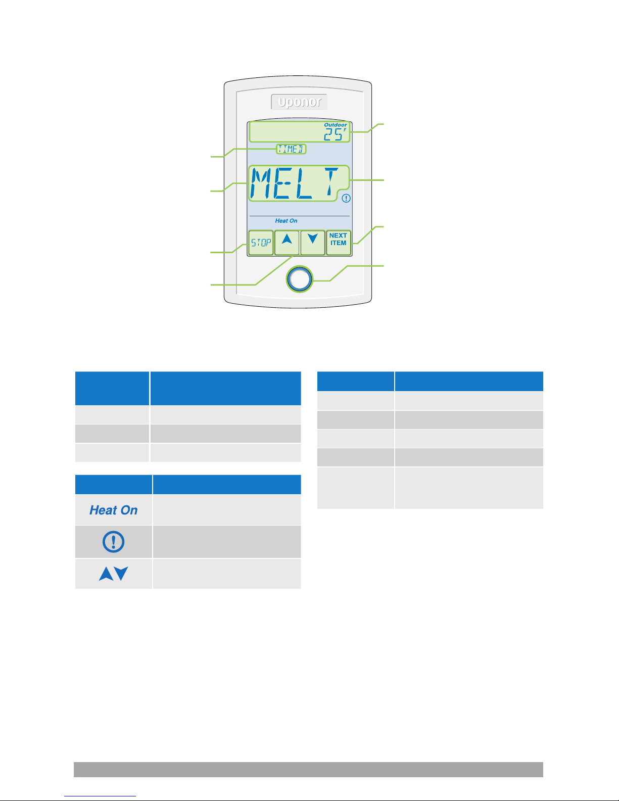
Home
button
ENTER
Status field
Touch to display
run time, outdoor
and slab temperature
Touch to quickly
enter the view menu
Touch to go to the next setting
Home button returns to the
Home screen; press and hold
for 3 seconds to access
programming menus
Operation field
Touch to melt or stop
Touch to adjust settings
User interface
Display
Operational
field
Action
MELT System is melting snow or ice.
IDLE System is idling.
OFF System is off.
Status field Action
WWSD System is melting snow or ice.
CWCO System is idling.
TIMED System is in storm operation.
WARM System is off.
PEND
Pending; the system has
detected water, but it is too
cold to operate.
Symbols Definition
HEAT ON
Heat is turned up.
WARNING SYMBOL
An error is present.
ARROWS
Adjusts the displayed setting.
Page 13
Single-zone snow melt control installation and operation manual | 13
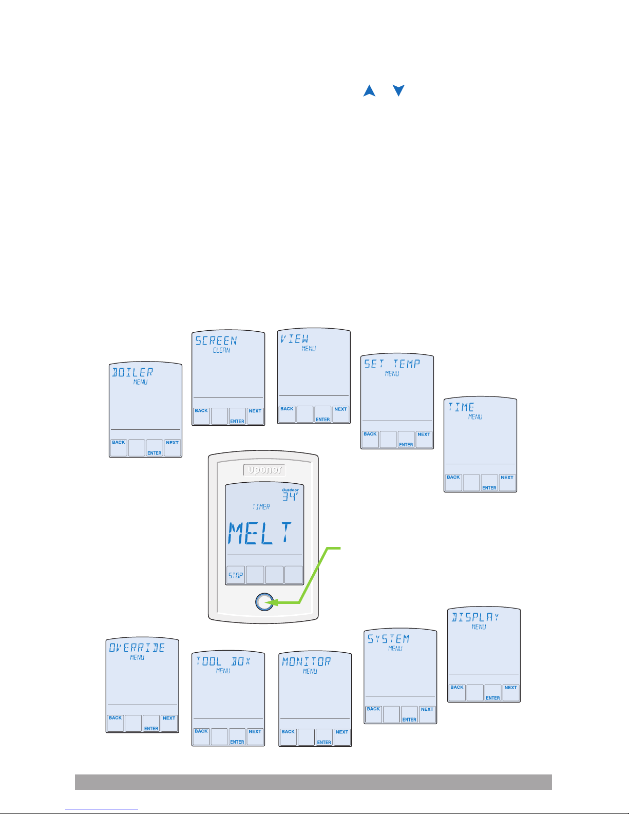
Programmable settings
Programming menus
Press and hold the Home button for 3
seconds to enter the programming menus.
The control returns to the last programming
menu previously used.
Select a programming menu
• Touch NEXT to advance
(clockwise in below illustration)
to the next menu.
• Touch BACK to go backwards
(counterclockwise in below illustration)
through the menus.
• Touch ENTER to enter a menu.
Setting items
• Touch or arrows to adjust the setting
if required.
• Touch NEXT ITEM to advance to the next
item within the menu.
• Touch BACK ITEM to go backwards to
the previous item within the menu.
• To return to the parent menu after
changing a setting, press and release
the Home button.
• To return to the Home screen, press and
release the Home button twice or wait
30 seconds to automatically return to
the Home screen.
Press and hold for
3 seconds to access
the programming menus.
Page 14

14 | uponorpro.com
Access levels and access
level lock
The control is shipped pre-programmed
with common settings. The control has an
Installer access level that allows full access
to all settings and a user access level that
restricts the number of settings available.
The control defaults to the User access
level after 12 hours of operation.
To change to the Installer access level:
• In the Toolbox menu, locate Access.
• Adjust the access level to Installer by
pressing the up or down button. This will
permit setting changes to the control.
View menu (1 of 2)
The View menu displays the current operating temperatures and status information
of the system.
Field
Range Access Description Set to
– – –,
-76 to 149ºF
(-60 to 65ºC)
User
Installer
OUTDOOR — Current outdoor air temperature
as measured by the local outdoor sensor.
Conditions: Application Mode is set to PWM,
Boil or Elec.
– – –,
-76 to 149ºF
(-60 to 65ºC)
Installer
SLAB TARGET — This field displays the
calculated slab target of the snow melting
system. Three dashes (– – –) display when
the snow melt control is off.
Conditions: Application Mode is set to PWM,
Boil or Elec and a snow/ice sensor or slab
sensor is installed.
-76 to 149ºF
(-60 to 65ºC)
User
Installer
SLAB — Current slab temperature as
measured by the control.
Conditions: Application Mode is set to PWM,
Boil or Elec and a snow/ice sensor or slab
sensor is installed.
DRY or WET
User
Installer
WATER SENSOR — Current status of the
water detection sensor.
Conditions: A snow/ice sensor or snow
sensor is installed.
– – –,
70 to 200ºF
(21.0 to 93.5ºC)
Installer
BOILER TARGET — This field displays
the calculated boiler target of the snow
melt system. Three dashes (– – –) display
when the snow melt control is not operating
the boiler.
Conditions: Application Mode is set to Boil.
-58 to 212ºF
(50.0 to
100.5ºC)
Installer
SUPPLY — Shows the current system supply
temperature as measured by the control.
Conditions: Application Mode is set to PWM
or Boil.
Page 15

Single-zone snow melt control installation and operation manual | 15
View menu (2 of 2)
The View menu displays the current operating temperatures and status information
of the system.
Field
Range Access Description Set to
0 to 100% Installer
BOILER RATE — Shows the current firing
rate of the modulating boiler.
Conditions: Application Mode is set to Boil
and Boiler Type is set to Mod (modulating
boiler).
OFF or ON
User
Installer
HEAT RELAY — Shows the current status of
the heat relay. The boiler or pump is on when
ON is displayed. The boiler or pump is off
when OFF is displayed.
Conditions: Application Mode is set to PWM,
Boil or Elec.
0 to 100% Installer
PWM RATE — Shows the current duty cycle
rate of the zone or boiler for each 20 minute
cycle.
Conditions: Application Mode is set to PWM
or Elec. Not visible when Manual Override is
not Auto.
OFF or ON
User
Installer
SYSTEM PUMP RELAY — Shows the current
status of the system pump relay.
Conditions: Application Mode is set to PWM
or Boil and Auxiliary Relay is set to SYS
(system pump).
OFF or ON
User
Installer
ALERT RELAY — Shows the current status
of the alert relay.
Conditions: Application Mode is set to PWM
or Boil and Auxiliary Relay is set to ALRT
(alert) or Application Mode is set to Elec.
00:00 to
24:00 hours
User
Installer
MANUAL MELT TIME — When manually
started, the display shows the remaining run
time before shutting off.
Conditions: Application Mode is set to PWM,
Boil or Elec.
00:00 to
6:00 hours
User
Installer
ADDITIONAL MELT TIME — When
automatically started by the Pavement
Snow and Ice Sensor, the display shows the
remaining run time before shutting off.
Conditions: Application Mode is set to PWM,
Boil or Elec and the Pavement Snow and Ice
Sensor (A3040090) is installed.
Page 16

16 | uponorpro.com
Set Temp menu
The Set Temp menu selects the operating temperatures of the snow melt system.
Field
Range Access Description Set to
32 to 95ºF
(0.0 to 35.0ºC)
Default = 36ºF
(2.0ºC)
User
Installer
MELTING — Selects the desired surface
temperature of the snow melt surface
when melting.
Conditions: Application Mode is set to PWM,
Boil or Elec.
OFF, 20 to
95ºF
(-6.5 to 35.0ºC)
Default = OFF
Installer
IDLING — Selects the desired surface
temperature of the snow melt surface when
idling. Idling pre-heats the slab when the
slab is dry but cold and allows faster reaction
time to reach the melting temperature.
(Recommended for commercial use only.)
Conditions: Application Mode is set to PWM,
Boil or Elec.
0:30 to
24:00 hours
Default =
4:00 hours
User
Installer
MANUAL MELT RUN TIME — Selects
the amount of running time when manually
starting the system.
Conditions: Application Mode is set to PWM,
Boil or Elec.
0:00 to
6:00 hours
Default =
0:00 hours
Installer
ADDITIONAL MELT TIME — Selects the
amount of additional melting time after the
Pavement Snow and Ice Sensor is dry. This
allows low spots on the slab to fully dry before
the snow melting system is shut off.
Conditions: Application Mode is set to
PWM, Boil or Elec and a Snow/Ice Sensor
is set to 090.
AUTO, MIN, -2,
-1, MID, +1, +2,
MAX
Default = AUTO
Installer
WATER SENSITIVITY — Selects how
sensitive the Pavement Snow and Ice
Sensor or the Aerial Snow Sensor is to
water detection.
Conditions: Snow/Ice Sensor is set to the
Pavement Snow and Ice Sensor or Aerial
Snow Sensor.
AUTO, 32 to
95ºF
(0.0 to 35.0ºC)
Default =
AUTO
Installer
WARM WEATHER SHUT DOWN — Selects
the temperature at which to shut down the
snow melting system during warm weather.
This allows the snow or ice to melt off the
slab naturally.
Conditions: Application Mode is set to PWM,
Boil or Elec.
OFF, -30 to
50ºF
(-34.5 to
10.0ºC)
Default = 10ºF
(-12.0ºC)
Installer
COLD WEATHER CUT OUT — Selects the
temperature at which to shut down the snow
melting system during extremely cold weather.
Below this temperature, the heat loss of the
slab exceeds the capacity of the boiler or
heating appliance.
Page 17

Single-zone snow melt control installation and operation manual | 17
Monitor menu
The Monitor menu provides information about the system’s operation and performance.
The Monitor menu is not available when the Application Mode is set to the Pavement
Snow and Ice Sensor.
Field
Range Access Description Set to
0 to 9999
hours
User
Installer
HEAT HOURS — Records the number of running
hours since the item was last reset. Touch the
number and then the ENTER key to reset to zero.
0 to 9999
hours
Installer
HEAT CYCLES — Records the numbers of
cycles of the heat relay since the item was last
reset. Touch the number and then the ENTER
key to reset to zero.
0 to 9999
hours
User
Installer
SYSTEM PUMP HOURS — Records the system
pump running hours since the item was last reset.
Touch the number and then the ENTER key to
reset to zero.
Conditions: Auxiliary Relay is set to SYS
(system pump).
-58 to 167ºF
(-50.0 to
75.0ºC)
Installer
SLAB HIGH — Records the highest slab
temperature since the item was last reset. Touch
the number and then the ENTER key to reset.
Conditions: Sensor is set to the Pavement Snow
and Ice Sensor or Slab Sensor is set to On.
-58 to 167ºF
(-50.0 to
75.0ºC)
Installer
SLAB LOW — Records the lowest slab
temperature since the item was last reset. Touch
the number and then the ENTER key to reset.
Conditions: Snow/Ice Sensor is set to the
Pavement Snow and Ice Sensor or Slab Sensor
is set to On.
-58 to 212ºF
(-50.0 to
100.0ºC)
Installer
OUTDOOR HIGH — Records the highest outdoor
temperature since the item was last reset. Touch
the number and then the ENTER key to reset.
-58 to 212ºF
(-50.0 to
100.0ºC)
Installer
OUTDOOR LOW — Records the lowest outdoor
temperature since the item was last reset. Touch
the number and then the ENTER key to reset.
-58 to 212ºF
(-50.0 to
100.0ºC)
Installer
SUPPLY HIGH —Records the highest supply
temperature since the item was last reset. Touch
the number and then the ENTER key to reset.
Conditions: Application Mode is set to PWM
or Boil.
-58 to 212ºF
(-50.0 to
100.0ºC)
Installer
SUPPLY LOW — Records the lowest supply
temperature since the item was last reset. Touch
the number and then the ENTER key to reset.
Conditions: Application Mode is set to PWM
or Boil.
Page 18

18 | uponorpro.com
Toolbox menu
The Toolbox menu is a location for system information and Test functions. If any errors are
present on the system, they will be located at the beginning of this menu.
Field
Range Access Description Set to
Installer (INST)
User (USER
Default = INST
User
Installer
ACCESS LEVEL — Selects the access level
of the control, which determines which menus
and items are available.
Conditions: Adjustable only when control
switch setting is set to UNLOCK.
Software
J1236A
Type 1058
User
Installer
SOFTWARE VERSION AND TYPE
NUMBER — Selects the access level of the
control, which determines which menus and
items are available.
Not applicable Installer
FACTORY DEFAULTS — Loads the factory
default settings. Press ENTER to load defaults.
See
Troubleshooting
Guide on p. 30
Installer
HISTORY - 1 THROUGH 5 — Displays a
history of any past errors that have occurred
on the system. Will clear after 30 days, or
press Up and Down buttons for one second to
manually clear. The last five history items will
display if present.
Display menu
The Display menu selects the temperature units and backlight options.
Field
Range Access Description Set to
or ºC
Default = ºF
User
Installer
UNITS — Selects Fahrenheit or Celsius as the
temperature units.
ON,
ON MELT,
OFF
Default =
ON MELT
User
Installer
BACKLIGHT — Selects how the display
backlight operates.
ON = Always on
ON MELT = On when melting, off when not
melting
This provides a visual indicator to occupants that
the snow melting system is currently melting.
OFF = Always off
Page 19

Single-zone snow melt control installation and operation manual | 19
Override menu
The Override menu allows an operator to manually test each relay and manually start the
system.
Field
Range Access Description Set to
Hydronic
AUTO,
HAND,
MAX,
PRGE, OFF
Electric
AUTO, AND,
TEST, OFF
Default =
AUTO
Installer
MANUAL OVERRIDE — Manually overrides
the normal automatic operation of the control to
test the equipment or operate the system at the
maximum temperature limits.
AUTO = Normal operation
HAND = Manual override of each relay output
MAX = Operate hydronic system at maximum heat
TEST = Operate electric system for 10 minutes
PRGE = Hydronic system purge operates pumps
to help bleed air from the system
OFF or ON
Default =
OFF
Installer
SYSTEM PUMP RELAY — Manually turns on the
system pump during the HAND Manual Override.
OFF or ON
Default =
OFF
Installer
HEAT RELAY — Manually turns on the heat
during the HAND Manual Override.
0 to 100%
Default =
0%
Installer
BOILER PERCENT — Manually sets the
modulating boiler firing rate during the HAND
Manual Override.
Conditions: Application Mode is set to Boil.
OFF or ON
Default =
OFF
Installer
ALERT RELAY — Manually turns on the alert
relay during the HAND Manual Override.
Conditions: Application Mode is set to PWM or
Boil and Alert Relay is set to ALRT (alert) or the
Application Mode is set to Elec.
0:10 to
72:00 hours
Default =
0:10 hours
Installer
OVERRIDE TIME — Selects the amount of time
that the HAND Manual Override is in effect before
returning to Automatic operation.
0:10 to
72:00 hours
Default =
24:00 hours
Installer
MAXIMUM PURGE TIME — Selects the amount
of time that the PURGE Manual Override is in
effect before returning to Automatic operation.
Conditions: Application Mode is set to PWM
or Boil.
0:10 to
72:00 hours
Default =
24:00 hours
Installer
MAXIMUM HEAT TIME — Selects the amount
of time that the MAX HEAT Manual Override is in
effect before returning to Automatic operation.
Conditions: Application Mode is set to PWM
or Boil.
Page 20

20 | uponorpro.com
System menu
The System menu provides settings on how to congure and operate the mechanical
equipment.
Field
Range Access Description Set to
PWM, BOIL,
ELEC,
Default =
PWM
Installer
APPLICATION MODE — Select the control
application mode.
PWM = Hydronic pulse width modulation
BOIL = Hydronic boiler heats snow melting system
ELEC = Electric snow melt
NONE, 090,
095
Default =
090
Installer
SNOW/ICE SENSOR — Selects if a Pavement
Snow and Ice Sensor or Aerial Snow Sensor is
installed.
OFF or ON
Default =
ON
Installer
SLAB SENSOR — Selects if a Slab Sensor for
Aerial Snow Sensor is installed to measure the
slab temperature.
Conditions: Application Mode is set to PWM,
Boil or Elec and Snow/Ice Sensor is set to None
or 095.
OFF or ON
Default =
ON
Installer
SLAB PROTECTION — Select if the slab should
be protected from large temperature differentials
to avoid cracking the concrete due to high tensile
stress.
Conditions: Application Mode is set to Boil and
Snow/Ice Sensor is set to 090 or Slab Sensor is
set to On.
OFF or ON
Default =
OFF
Installer
ECONOMELT — EconoMelt allows the user to
mechanically remove snow then manually start
the system to melt the thin snow layer or ice.
Conditions: Application Mode is set to PWM,
Boil or Elec.
SYS
(System
Pump)
or ALRT
(Alert)
Default =
SYS
Installer
AUXILIARY RELAY — Select if the auxiliary
relay should function as system pump or as
an alert.
Conditions: Application Mode is set to PWM
or Boil.
0.5 to 7.0
days, OFF
Default = 3.0
days
Installer
MAXIMUM MELT TIME — Select to limit
the amount of melting run time after snow is
automatically detected by the Pavement Snow
and Ice Sensor or Aerial Snow Sensor.
Conditions: Application Mode is set to PWM,
Boil or Elec.
Page 21

Single-zone snow melt control installation and operation manual | 21
Boiler menu
The Boiler menu provides settings on how to congure and operate the boiler.
Field
Range Access Description Set to
App mode =
Boil
MOD,
1STG,
EMS1,
EMS2
Default =
MOD
Installer
BOILER TYPE — Shows the type of boiler
connected to the control.
MOD = Modulating boiler
1STG = Single one-stage on-off boiler
EMS1 = Boiler staging controls
EMS2 = Viessmann modulating boilers with 0-10
V OpenTherm Module
0-10 or 4-20
Default =
0-10
Installer
BOILER MODULATION TYPE — Selects if the
modulating boiler accepts a 0-10 VDC or 4-20
mA input signal to control the boiler firing rate.
Conditions: Boiler Type is set to MOD
(modulating boiler).
0 to 50%
Default =
0%
Installer
BOILER MINIMUM MODULATION — Shows the
minimum-percent modulation of the boiler burner.
Conditions: Boiler Type is set to MOD
(modulating boiler).
OFF, 10 to
180 seconds
Default =
OFF
Installer
BOILER MODULATION DELAY — Shows the
delay time between the burner firing and the
boiler releasing to modulation.
Conditions: Boiler Type is set to MOD
(modulating boiler).
30 to 230
seconds
Default =
30 seconds
Installer
BOILER MOTOR SPEED — Shows the time
required for the modulating actuating motor to
fully open the gas valve or ramp the burner fan
from off to full speed on a modulating boiler. Set
to 30 seconds unless otherwise recommended
by the boiler manufacturer.
Conditions: Boiler Type is set to MOD
(modulating boiler).
AUTO, 2 to
42ºF
(1.0 to
23.5ºC)
Default =
AUTO
Installer
BOILER DIFFERENTIAL — Shows the
temperature differential that the control is to use
to cycle the boiler on and off (half above and half
below target).
Conditions: Boiler Type is set to MOD
(modulating boiler) or 1STG (one stage).
OFF, 50 to
180ºF
(10.0 to
82.0ºC)
Default =
OFF
Installer
BOILER MINIMUM — Shows the minimum
allowed boiler target temperature. Check the
boiler manufacturer’s manual for recommended
supply water temperatures.
Conditions: Application Mode is set to Boil.
Page 22

22 | uponorpro.com
Sequence of operation
Snow melting overview
A snow melting system can offer a safe,
convenient and cost-effective way to
remove snow and ice from surfaces.
Activating the snow melting system as
soon as the snow falls rather than waiting
for mechanical snow removal after snow
has accumulated is a safer alternative.
This eliminates slip hazards and reduces
the risk of injury by mechanized snow
melting equipment, thereby reducing
potential liability costs. Eliminating snow
plow equipment and corrosive salts also
reduces damage to the slab surface and to
the environment. Additionally, snow melting
systems, when controlled correctly, can be
cost competitive compared to mechanical
snow removal.
The snow melting control can operate in
one of three different ways:
• Melt: Heats the slab to melt snow or ice
• Idle: Pre-heats the slab just below freezing
to shorten the time required to melt snow
• Off: Snow melting system is off
The control display shows the control
operation in the home screen.
Slab temperature control
Controlling the slab temperature is critical
to minimizing the cost of snow melting. This
requires installation of the Pavement Snow
and Ice Sensor (A3040090) or Slab Sensor
for Aerial Snow Sensor (A3040073).
The sensor contains a built-in slab
temperature sensor. While the control
will continue to operate without a slab
sensor installed, operating costs will
be much higher.
The slab is operated using slab outdoor
reset. As the outdoor temperature gets
colder, the heat loss of the slab increases.
In order to keep the slab surface at a
constant temperature while operating, the
inner core of the slab must be heated above
the melt or idle temperature setting.
The amount that the slab inner core
temperature is above the melt or idle setting
is proportional to the outdoor temperature.
Since the slab sensor is installed below the
surface of the slab, it is not measuring the
true slab surface temperature, but rather the
inner core temperature.
The control automatically compensates for
this temperature difference. However, the
slab item in the View menu displays the
actual measured temperature, so it
is normal to view slab temperatures that
exceed the melt or idle temperature settings.
Melt operation
The snow melting system operates the
heating equipment to heat the slab from
a cold start or from the idle temperature
to reach the melt temperature setting to
melt snow or ice.
Melt operation can be triggered automatically
using the Pavement Snow and Ice Sensor,
the Aerial Snow Sensor or manually by
pressing a button. The melt temperature
setting affects calculated targets such as
the slab target and boiler target.
Surface temp. = 35˚F (1.7˚C)
Slab outdoor reset
Core (sensor) is warmer.
Decreasing air temperature
Slab surface temperature is constant.
Increasing slab core temperature
Page 23

Single-zone snow melt control installation and operation manual | 23
Manual start and timed stop
The snow melting system can be started
manually by touching the Melt key on the
control display.
Once manually started, the snow melting
system continues to operate until the time
set by the Manual Melt Run Time setting in
the Set Temp menu elapses.
If a manual start has been provided and a
sensor detects water, the control changes
from manual melt to automatic operation.
The snow melting system will continue
to operate until the sensor is dry and the
Additional Melt Time elapses.
Automatic start and stop
Automatic start and stop operation requires
the installation of a Pavement Snow and Ice
Sensor (A3040090). The control continually
monitors the sensor for the presence of
moisture and slab temperature conditions
in which snow or ice may be present. When
moisture is detected, the control will show
Sensor Water Wet in the View menu. When
the sensor is dry the control will show
Sensor Water Dry. The control includes a
Sensitivity setting in the Set Temp menu
that allows the installer to adjust the amount
of moisture required to start and stop
the melting operation. In areas with low
amounts of dust and/or air pollution, the
sensitivity may need to be increased.
The Sensitivity setting default is Auto,
and the control will automatically determine
the best suitable sensitivity setting for
the installation.
When moisture is detected and the slab
and outdoor temperatures are at or below
freezing, the control will automatically start
the snow melting system. As the snow or ice
melts and the slab dries off, the sensor also
dries off at the same time. When the sensor
is dry, the snow melt system automatically
shuts off. If there are low spots on the slab
surface that dry off slower than the sensor,
additional melting run time can be included
by adjusting the Additional Melt Time setting
in the Set Temp menu.
WWSD
Touch STOP key
Aerial Snow Sensor and slab dry
and MELT time elapses
Aerial Snow Sensor detects water
Touch MELT key
CWCO
Timed
melt
Idle
or
off
Touch
MELT
Melt
suspended
Enters
CWCO
Exits
CWCO
Pavement Snow
and Ice Sensor
(A3040090)
Pavement sensor and slab dry and
ADD MELT time elapses
Pavement sensor detects water
WWSD
Touch STOP key
Timed
melt
Idle
or
off
Touch MELT key
Page 24

24 | uponorpro.com
Melt
suspended
Enters
CWCO
Exits
CWCO
Pavement sensor and slab dry and
ADD MELT time elapses
Pavement sensor detects water
WWSD
Touch STOP key
Timed
melt
Idle
or
off
Touch MELT key
If the snow melting system is manually
stopped, the sensor must fully dry
before it is able to detect a new snow
fall and automatically start the snow
melting system.
EconoMelt
When a Pavement Snow and Ice
Sensor is installed, the installer can
choose to select to either automatically
or manually start the snow melting
system. Selecting EconoMelt to On
provides the option to remove the snow
using a snow plow or shovel and then
use the snow melting system to melt the
remaining thin layer of snow or ice that
mechanical snow removal methods are
unable to remove. The snow melting
system stops when the sensor is dry.
The factory default for EconoMelt is Off.
Melt
suspended
MeltOff
Enters
CWCO
WWSD
Touch STOP key
Touch START key
Pavement sensor and slab dry
and ADD MELT time elapses
Exits
CWCO
Automatic start and timed stop
Automatic start with a timed stop operation
requires the installation of an Aerial Snow
Sensor (A3040095). It is also highly
recommended to install a Slab Sensor for
Aerial Snow Sensor (A3040073) to regulate
the slab temperature and operate the snow
melting system at the highest possible
efciency.
The control continually monitors the sensor
for the presence of moisture and slab
temperature conditions in which snow
or ice may be present. When moisture
is detected, the control will show Sensor
Water Wet in the View menu. When the
sensor is dry the control will show Sensor
Water Dry. The control includes a Sensitivity
setting in the Set Temp menu that allows the
installer to adjust the amount of moisture
required to start and stop the melting
operation. In areas with low amounts of dust
and/or air pollution, the sensitivity may need
to be increased. The factory default is for
the Sensitivity setting is Auto. The control
automatically determines the best suitable
sensitivity setting for the installation.
Aerial
Snow Sensor
(A3040095)
Aerial
snow
sensor
Page 25

Single-zone snow melt control installation and operation manual | 25
Additional melting time
A Pavement Snow and Ice Sensor
(A3040090) automatically shuts off the snow
melting system when the water sensor is
dry. Due to the construction of the slab and
the layout of the heating pipe or electrical
cable, there may be areas that do not
melt completely. The Additional Melt
Time setting in the Set Temp menu allows
the installer to set additional melting time
after the sensor is dry.
Idle operation
When the snow melting system starts
from a cold temperature, there may be a
long time delay before the slab is warm
enough to melt snow. This time delay allows
snow to accumulate on the slab which is
not acceptable in some commercial and
institutional applications. To decrease the
start-up time, the slab can be pre-heated to
maintain a minimum temperature.
This is known as the Idle temperature.
Idling requires large energy consumption
and is generally recommended for
institutional and/or commercial installations
where safety concerns are paramount.
Idle is shown on the display when the
control is in idle operation.
When designing a snow melting system, an
engineer may specify the amount of allowed
snow accumulation as the Snow-free Area
Ratio. There are three different levels. A
Snow-free Area Ratio of 1 is dened as a
system that melts all snow as it falls with
no allowed accumulation. This requires
that the Idle temperature be set just below
freezing. Examples of these types
of applications include:
• Hospital emergency areas
• Helicopter landing pads
• Parking garage ramps
A Snow-free Area Ratio of 0.5 is dened
as a system with partial snow accumulation
on the slab but not in all areas.
These types of systems may also use idling
but usually set at a temperature several
degrees below freezing to reduce energy
consumption. Applications may include:
• Steep residential driveways
• Commercial sidewalks
• Loading docks
When moisture is detected and both
the slab and outdoor temperatures
are below the Melting setting, the
control automatically starts the snow
melting system. The snow melting
system operates to heat the slab
to the slab target temperature and
continues to operate until the time set
by the Manual Melt Run Time in the
Set Temp menu elapses.
Pavement snow
and ice sensor
Dry
WWSD
Touch STOP key
Aerial Snow Sensor and slab dry
and MELT time elapses
Aerial Snow Sensor detects water
Touch MELT key
CWCO
Timed
melt
Idle
or
off
Page 26

26 | uponorpro.com
A Snow-free Area Ratio of 0 is dened as
a system that allows snow accumulation.
These systems operate the snow melting
system from a cold start resulting in the
lowest energy consumption costs and the
longest times to start melting snow.
In this case, set the Idle to off. This
is recommended for most residential
applications:
• Flat residential driveways
• Patios
• Residential sidewalks
Some systems are designed for keeping
a slab surface free of ice rather than free
of snow. The most common applications
include:
• Car wash bays and aprons
• Aircraft hanger aprons
• Turf conditioning on golf course greens
These systems require the use of idling at
or near freezing throughout the winter and
may result in high energy consumption.
Warm weather shut down
During warm weather, the slab is warm
enough to naturally melt snow or ice. The
control has a Warm Weather Shut Down
(WWSD) setting in the Set Temp menu that
prevents the control from entering Melt or
Idle operation in order to conserve energy.
The control shows WWSD on the display
when WWSD is in effect.
Automatic (Auto)
The control enters WWSD when both
the slab temperature of the zone and the
outdoor temperature exceed the Melt
temperature setting by more than 2ºF (1ºC).
Manual WWSD
The control enters WWSD when the
outdoor air temperature exceeds the
WWSD setting by 1ºF (0.5ºC) and when
the slab temperature exceeds 34ºF (1ºC).
The control exits WWSD when the outdoor
air temperature falls 1ºF (0.5ºC) below the
WWSD setting or if the slab temperature
falls below 34ºF (1ºC). This allows the Melt
temperature setting to be set higher than
the WWSD. This is useful when high slab
temperatures are required to melt the snow
or ice. An example of this are installations
using paving bricks on top of sand and
concrete layers.
Cold weather cut out
Maintaining the melting or idling
temperature during extremely cold
temperatures is not only expensive but may
be impossible if the heat loss of the slab
exceeds the input capacity of the heating
plant or electric cable. The control turns the
snow melting system off when the outdoor
air temperature drops below the Cold
Weather Cut Out (CWCO) temperature
and the slab is below freezing. This is a
safety and energy-saving measure. The
control shows CWCO on the display when
CWCO is in effect. When the temperature
reaches the CWCO setting in an actively
melting system with a Pavement Snow and
Ice Sensor, melting is suspended until the
outdoor temperature rises above the CWCO
setting. If a Pavement Snow and Ice Sensor
is not installed, melting is permanently
stopped when CWCO is in effect. Melting
does not resume when the temperature
rises above the CWCO setting.
Page 27
Single-zone snow melt control installation and operation manual | 27
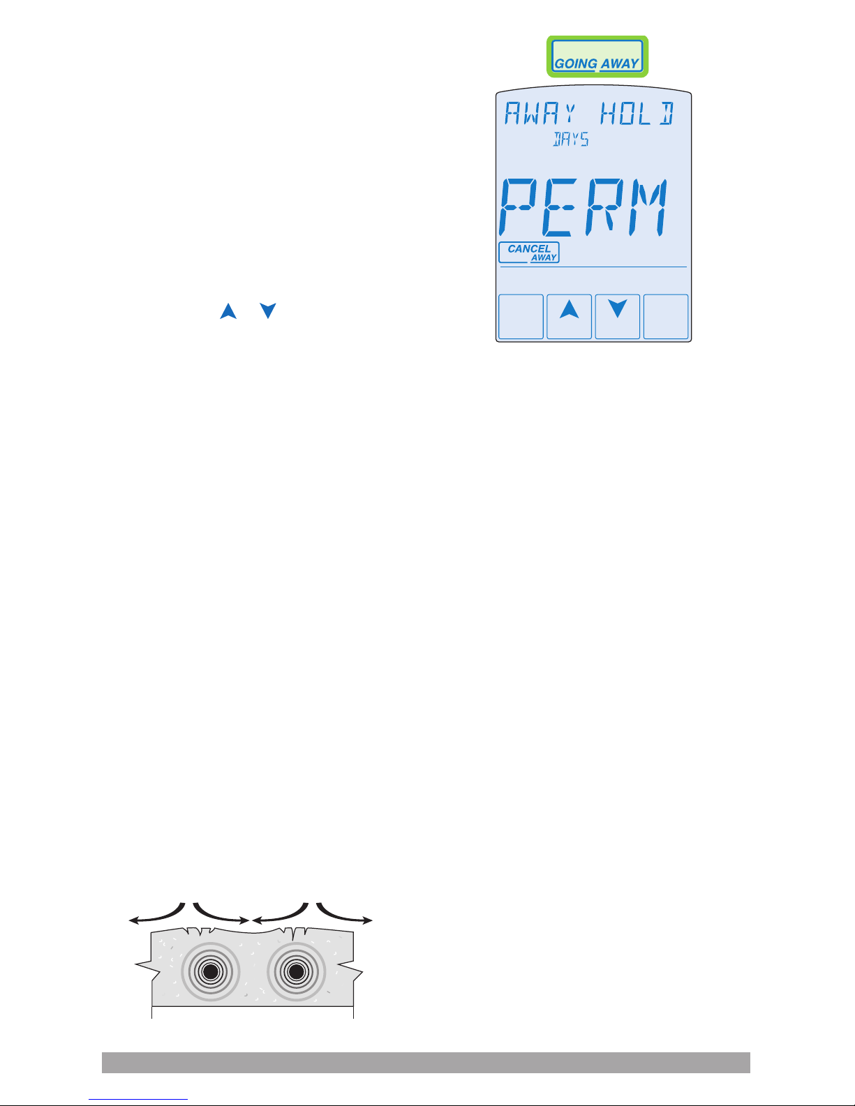
Away key
Disable the snow melting system with the
Away Key. To turn on the Away Key, go to
the Display menu.
• Select AWAY KEY.
• Select ON.
To activate the Away Override (once the
Away Key has been activated).
• Touch “Going Away” on the screen.
• Select PERM (permanent) or a number of
days using the or arrow. Range is 1
to 180 days.
• Press the home button to accept the
setting or leave the screen
untouched for several seconds.
• “Away” is displayed on the home screen
until the number of days expires.
• Touch “Cancel Away” to cancel at any time
Slab protection
In a hydronic snow melting system, the
boiler or heating plant capacity may be
much larger than the load of the snow
melting zones. This can result in large
temperature differentials between the
supply water temperature and the slab,
creating large tensile stresses on
the slab.
Concrete is weak to tensile forces and when
repeatedly exposed to tensile loads the
concrete may crack. This may be prevented
by selecting the Protect Slab setting in the
System menu to On. The control measures
and limits the temperature differential
between the supply water and the slab.
Application modes
The snow melting control can operate either
an electric or a hydronic snow melting
system. A hydronic system can be further
categorized as either boiler or pulse width
modulation (PWM) zone operation as well
as whether the boiler plant is dedicated or
non-dedicated for the snow melting system.
A dedicated boiler only provides heat from
the snow melting system. A non-dedicated
boiler provides heat for the snow melting
system in addition to the space heating and/
or domestic hot water system. The control
requires that one of the following Application
Modes is selected in the System menu:
• PWM: Pulse width modulation
• BOIL: Boiler operation
• ELEC: Electrical operation
Tensile stresses
Page 28

28 | uponorpro.com
Electric operation
The control operates the heat relay on
a 20-minute PWM cycle. The heat relay,
in turn, activates a line voltage electrical
contactor to energize the electrical cable
heater installed in the slab. The heat relay
on time is determined by the calculated
slab target and by the measured slab
temperature reading.
As the slab temperature reaches the
slab target, the on time per cycle of the
heat relay is reduced to prevent the slab
temperature from overshooting. If no
slab sensor is installed, the heat relay
remains on 100% of the time until the Melt
operation has completed. Idle operation
is not available when a slab sensor is not
installed. The electric operation requires
the installation of an outdoor sensor. A slab
sensor is highly recommended to reduce
operating costs.
Pulse width modulation
operation
The Application Mode should be set to
Pulse Width Modulation (PWM) when the
boiler or heat source is non-dedicated to
the snow melting system and there is no
mixing system. The snow melting system
is considered to be a zone together with
space heating and the domestic hot water
system. The control operates the heat
relay on a 20-minute PWM cycle. The
heat relay, in turn, activates the hydronic
heating system zone pump or zone valve.
The heat relay on time is determined by the
calculated slab target and by the measured
slab temperature reading. As the slab
temperature reaches the slab target, the on
time per cycle of the heat relay is reduced
to prevent the slab temperature from
overshooting. If no slab sensor is installed
the heat relay remains on 100% of the time
until the Melt operation has completed.
Idle operation is not available when a slab
sensor is not installed.
The hydronic PWM operation requires the
installation of an outdoor sensor and a
supply sensor. The supply sensor is
installed on the glycol antifreeze system
supply pipe and allows the control to
provide slab protection and as well as
supply zone priority. A slab sensor is highly
recommended to reduce operating costs.
Boiler operation
The Application Mode should be set to
Boil when the snow melting system has a
dedicated boiler or heat source. The boiler
is piped primary-secondary to the snow
melting loop, allowing the boiler to re
on and off while allowing continuous ow
through the snow melting system loop.
The control calculates a Boiler Target
based upon the Slab Target which,
in turn, is based upon the measured
outdoor temperature and the Melt or Idle
temperature setting. The control can
operate a boiler in one of four different
methods: single stage, modulating boiler,
EMS1 or EMS2. The Boiler Target is shown
in the View menu. Settings for the boiler
operation are located in the Boiler menu.
Note: The boiler operator, or aquastat,
remains in the burner circuit and acts
as a secondary upper limit on the
boiler temperature. The boiler aquastat
temperature setting must be adjusted
above 200ºF (93.5ºC) in order to
prevent short cycling of the burner.
Page 29

Single-zone snow melt control installation and operation manual | 29
Single stage on/off boiler (1STG)
The control turns the heat relay on or off
to re the boiler in order to maintain the
Boiler Target temperature. The boiler supply
temperature operates on a differential that is
half above and half below the boiler target.
The status of the boiler is shown by the Boil
Relay item in the View menu.
Modulating boiler (MOD)
The control can operate a single hot-water
modulating boiler using the Mod output and
the Heat contact. The control operates the
boiler by rst switching the heat contact to
allow the modulating boiler to go through
the ignition sequence (the heat contact may
not be required on all modulating boilers).
A 0-10 VDC or 4-20 mA analog signal is
then used to modulate the boiler ring rate
starting at 50% (5 VDC or 12 mA signal)
for 30 seconds. After the 30-second delay
has elapsed, the control will then allow the
boiler to modulate down to the Minimum
Modulation setting and hold it there for the
Modulation Delay time setting.
After the modulation delay has elapsed,
the control uses PID logic to change the
boiler ring rate signal in order to satisfy the
boiler target temperature. When the ring
rate signal is reduced down to the minimum
modulating setting and the boiler supply
temperature exceeds the boiler target by half
the differential, the control will shut off the
boiler burner. The modulating signal output
is shown by the Boil Rate in the View menu.
The Modulation Delay setting is determined
by the boiler manufacturer. It is the amount
of time that the burner must operate before
the internal boiler control allows an external
signal to operate the burner.
The Motor Speed sets the rate at which the
modulating electrical signal can change. For
most modulating boilers with an ECM fan,
the motor speed can be set to 30 seconds.
For commercial boilers with a mod motor,
set the motor speed according to the time
required by the mod motor to travel from the
closed to the open position.
EMS1
The EMS1 signal is a method for the snow
melting control to send the boiler target
temperature to a compatible boiler control
(if used). The control provides a 0-10 VDC
signal proportional to the boiler target and
turns on the heat relay to operate the boiler
to maintain the Boiler Target temperature.
EMS2
The EMS2 signal is a method for the snow
melting control to send the boiler target
to a Viessmann boiler that supports the
OpenTherm temperature targeting. Typical
boilers include the Viessmann Vitodens
100-W and 200-W. The boiler may require
an OpenTherm Input Module 0-10V.
Contact Viessmann for details.
The control provides a 0-10 VDC signal
proportional to the boiler target and turns
on the heat relay to operate the boiler to
maintain the Boiler Target temperature.
EMS1 conversion table
0-10 VDC Boiler target
0 – – – (Off)
1 50ºF (10ºC)
2 68ºF (20ºC)
3 86ºF (30ºC)
4 103ºF (39ºC)
5 121ºF (49ºC)
6 139ºF (59ºC)
7 157ºF (69ºC)
8 174ºF (79ºC)
9 192ºF (89ºC)
10 210ºF (99ºC)
Page 30
30 | uponorpro.com
Exercising
In a hydronic snow melting system, the
control operates the system pump every
three days to prevent pump seizure.
Alert relay
The control includes an auxiliary relay that
can be congured to be either a system
pump or an alert output. When the Auxiliary
Relay setting in the System menu is set to
Alert, the relay closes whenever there is a
local error code. The Alert Relay is connected
to the input power R and provides a 24 VAC
powered signal when closed. An isolation
relay may be installed if a dry contact switch
is required on the third-party equipment.
Pump post purge
After a zone has nished heating, the boiler
or heat source is shut off and the zone
continues to operate for 20 seconds to
post purge heat from the boiler to the zone.
Troubleshooting
It is recommended to complete all wiring to ensure trouble free operation. Should an error
occur, simply follow these steps:
1. Find: If the control ashes on the screen, it is indicating a problem on the system.
2. Identify: Hold the Home button for 3 seconds, touch the NEXT key to locate the Toolbox
Menu, then touch the ENTER key. The error code should appear as the rst item.
3. Solve: Use the chart below to match the error code to the one on the control. Use the
description to solve the problem
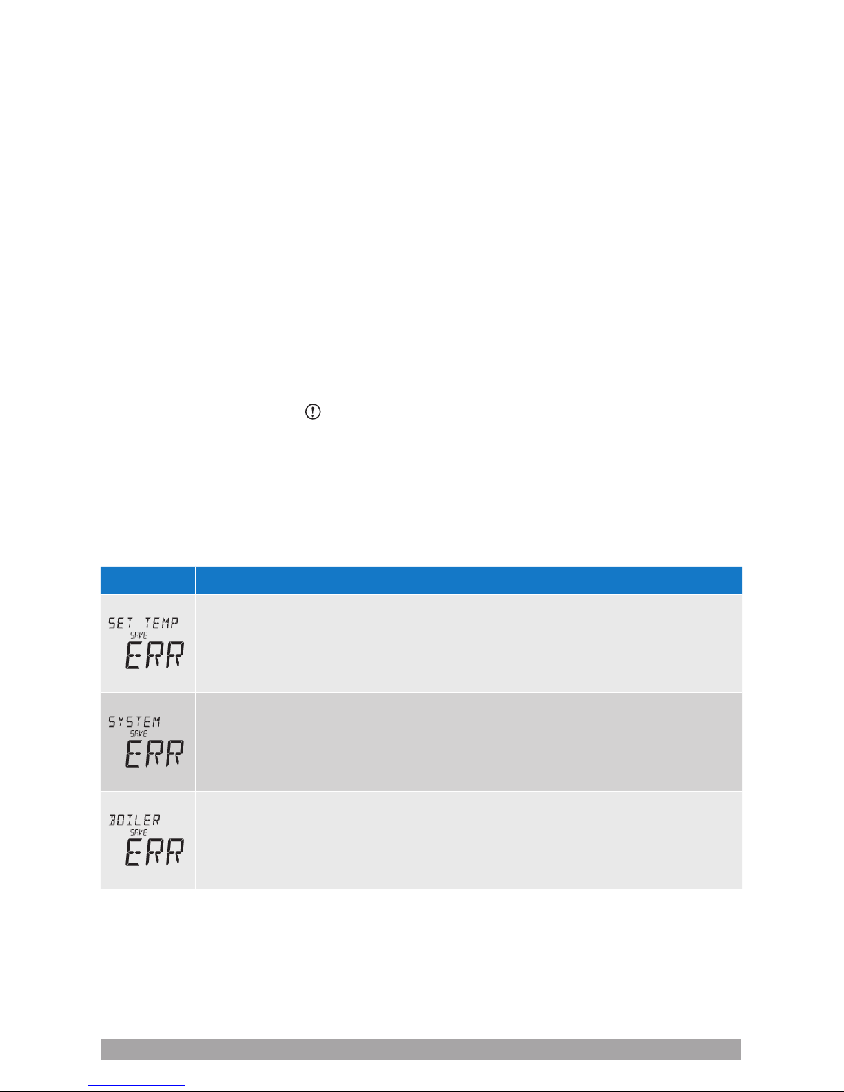
Error messages
Field
Description
SET TEMP MENU SAVE ERROR — The control failed to read the Set Temp menu
settings from memory and has reloaded the factory default settings. The control stops
operation until all settings in the Set Temp menu are checked.
To clear the error, set the access level to Installer and check all settings in the Set
Temp menu.
SYSTEM MENU SAVE ERROR — The control failed to read the System menu
settings from memory and has reloaded the factory default settings. The control
stops operation until all settings in the System menu are checked.
To clear the error, set the access level to Installer and check all settings in the
System menu.
BOILER MENU SAVE ERROR — The control failed to read the Boiler menu settings
from memory and has reloaded the factory default settings. The control stops
operation until all settings in the Boiler menu are checked.
To clear the error, set the access level to Installer and check all settings in the
Boiler menu.
Page 31

Single-zone snow melt control installation and operation manual | 31
Error messages
Field
Description
MAXIMUM MELT TIME ERROR — The control has operated in melting for the time
set by Maximum Melt Days setting located in the System menu. This error is usually
created when there is a mechanical system failure resulting in the snow melt slab not
heating correctly.
Clear the error message by touching the Cancel key while viewing the error
message. Use the Manual Override menu to manually check that each component of
the mechanical system is operating correctly.
If necessary, change the Maximum Melt Days setting to a longer time period or to Off.
OUTDOOR SENSOR SHORT CIRCUIT ERROR — Due to a short circuit, the control
is unable to read the outdoor sensor. The control continues to operate and assumes
an outdoor temperature of 32ºF (0ºC). Energy saving features such as Warm
Weather Shut Down (WWSD) and Cold Weather Cut Out (CWCO) are disabled.
Check the outdoor sensor wire for short circuits according to the sensor installation
manual. It may be necessary to replace the outdoor sensor. Once the error has been
corrected, the error message automatically clears.
OUTDOOR SENSOR OPEN CIRCUIT ERROR — Due to an open circuit, the control
is unable to read the outdoor sensor. The control continues to operate and assumes
an outdoor temperature of 32ºF (0ºC). Energy saving features such as Warm
Weather Shut Down (WWSD) and Cold Weather Cut Out (CWCO) are disabled.
Check the outdoor sensor wire for open circuits according to the sensor installation
manual. It may be necessary to replace the outdoor sensor. Once the error has been
corrected, the error message automatically clears.
SUPPLY SENSOR SHORT CIRCUIT ERROR — Due to a short circuit, the control
is unable to read the supply sensor. When set to App Mode Boiler, the control stops
operation and does not provide any heat. When set to App Mode PWM the control
continues melting or idling.
Check the supply sensor wire for short circuits according to the sensor installation
manual. It may be necessary to replace the supply sensor. Once the error has been
corrected, the error message automatically clears.
SUPPLY SENSOR OPEN CIRCUIT ERROR — Due to an open circuit, the control
is unable to read the supply sensor. When set to App Mode Boiler, the control stops
operation and does not provide any heat. When set to App Mode PWM the control
continues melting or idling.
Check the supply sensor wire for open circuits according to the sensor installation
manual. It may be necessary to replace the supply sensor. Once the error has been
corrected, the error message automatically clears.
SLAB SENSOR SHORT CIRCUIT ERROR — Due to a short circuit, the control is
unable to read the Slab Sensor for Aerial Snow Sensor (A3040073). Idling is disabled
and energy saving features such as Warm Weather Shut Down (WWSD) and Cold
Weather Cut Out (CWCO) are operated using the outdoor temperature only.
Check the slab sensor wire for short circuits according to the sensor installation
manual. It may be necessary to replace the slab sensor. Once the error has been
corrected, the error message automatically clears.
Page 32

32 | uponorpro.com
Symptoms and solutions
Symptom
Look for… Corrective action
LCD display is off Power to control Use electrical meter to measure 24 VAC voltage on input
power R and C terminals.
System pump
always on
Display shows idle Idle operation requires that the system pump operate
continuously while below the melting temperature setting.
Blue short Dirt or salt on
sensor
The sensor requires regular cleaning. Avoid using road
salt on the snow melting slab.
Slab is above melt
temperature
Slab target The slab is heated to the slab target.
Heat on not shown Check wiring of the system pump. The system pump
operates continuously during melt and idle operation.
The heat source must be wired to operate together with
the heat relay.
System running
with no snow
Idle Idling heats the slab when the temperature falls below
the Idle temperature.
Melt During Cold Weather Cut Out (CWCO), the system
is shut off. If shut off during a melt cycle, the system
resumes melting once the outdoor temperature is above
CWCO.
Timed melt System manually started.
Snow on slab but
system did not start
Off System has been manually stopped and the Pavement
Snow and Ice Sensor or the Aerial Snow Sensor never
dried, thereby preventing the system to automatically start.
Page 33

Single-zone snow melt control installation and operation manual | 33
Job record
Set Temp menu settings
Item
Setting
Melting
Idling
Manual melt run time
Additional melt time
Water sensitivity
WWSD
CWCO
System menu settings
Item
Setting
Application mode
Snow/ice sensor
Slab sensor
Slab protection
EconoMelt
Auxiliary relay
Maximum melt time
Warning: This product contains chemicals known to the State of California to
cause cancer and birth defects or other reproductive harm. For more information,
visit http://oehha.ca.gov/prop65.html.
Boiler menu settings
Item
Setting
Boiler type
Boiler modulation type
Boiler minimum
modulation
Boiler modulation
delay
Boiler motor speed
Boiler differential
Boiler minimum
Display menu settings
Item
Setting
Units
Backlight
Page 34

34 | uponorpro.com
Technical data
Control Microprocessor control; not a safety (limit) control
Packaged weight 1.3 lb. (590 g)
Dimensions 5" H x 3¼" W x 15⁄16" D (127mm x 82mm x 23mm)
Enclosure White PVC plastic, NEMA type 1
Ambient conditions
-4 to 122ºF (-20 to 50ºC), < 90% RH non-condensing, outdoor use permitted
when installed inside a NEMA 3 enclosure
Power supply 24 VAC ±10%, 60 Hz, Class 2, 16 VA standby, 100 VA fully loaded
Relay capacity 24 VAC 2 A, 3.6 A combined
Modulating output
0-10 VDC, 500 Ω minimum load impedance, 4-20 mA 1 kΩ maximum
load impedance
Sensors NTC thermistor, 10k @ 77ºF (25ºC ± 0.2ºC) ß=3892
Included Outdoor sensor and slab sensor
Optional
Pavement Snow and Ice Sensor (A3040090), Aerial Snow Sensor
(A3040095) and Slab Sensor for Aerial Snow Sensor (A3040073)
Page 35

Single-zone snow melt control installation and operation manual | 35
Page 36

uponorpro.com
SnMltControl_InstallOperMan_70162_0817, Copyright © 2017 Uponor. Printed in the United States.
Uponor Inc.
5925 148th Street West
Apple Valley, MN 55124
USA
T 800.321.4739
F 952.891.2008
Uponor Ltd.
6510 Kennedy Road
Mississauga, ON L5T 2X4
CANADA
T 888.994.7726
F 800.638.9517
 Loading...