

Page 1
Zone Control
Module Instructions
RADIANT HEATING SYSTEMS
ZONE CONTROL MODULE
INSTRUCTION SHEET
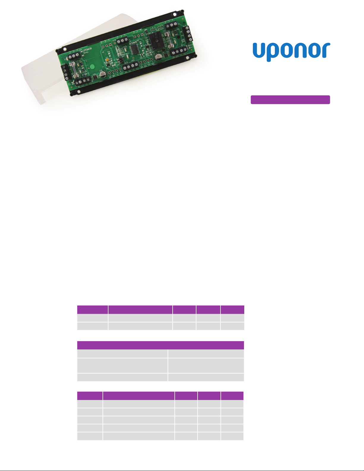
The Uponor Zone Control Module
is a printed circuit control and
diagnostic device designed for
use with Uponor Thermostats,
Motorized Valve Actuators (MVAs),
Thermal Actuators and Zone Valves.
Two-wire Compatibility
An interinal timer circuit was added
for use with the two-wire thermal
actuators. This timer will automatically
activate the red LED after three
minutes to ensure the actuator(s) are
open and will close the ES terminals
for external relays or devices.
The module provides the following:
• A connection to the power
supply transformer
• Interconnections between the
individual thermostats and their
respective MVAs, thermal actuators
or zone valves
• The connection between the end
switches and the pump or boiler relay
Part No. Part Description Width Height Depth
A3031003 Three-zone Control Module 7.25" 2.75" 1"
A3031004 Four-zone Control Module 7.25" 2.75" 1"
Table 1: Product Descriptions
Specifications
Power Input: 24VAC
End-switch Circuit: Dry contact equivalent nominal
Recommended Thermostat Wire Size: 18GA
Table 2: Specifications
Part No. Part Description 50VA 75VA 100VA
A3020522 Motorized Valve Actuator, four-wire 7 10 14
A3010522 Thermal Actuator, four-wire 12 18 25
A3020416 Thermal Actuator, two-wire 12 18 25
A3030522 Thermal Actuator, two-wire 12 18 25
A3030523 Thermal Actuator, two-wire 12 18 25
Table 3: Maximum Number of Actuators on a Transformer (Rating at 24VAC)
The modules are internally fused
for protection from over current or
direct shorts from the power supply
transformer. The end-switch circuit is
also protected from over current and
a 2-amp fuse is factory installed.
Note: Because the ES terminals are
completely isolated, the modules no
longer require separate transformers
on R, C and ES terminals. Pay careful
attention to transformer sizing if
using only one transformer.
Zone Configurations
The Uponor Zone Control Modules
are available in both three- and
four-zone configurations. Boards can
be ganged together to expand the
number of zones. Allow 1⁄4" between
boards when mounting end-to-end.
Connecting Instructions
Refer to the following instructions
to properly connect the module.
1. Connect modules in series via
a module jumper (provided).
24VAC, 2A maximum
2. Fasten the jumper within the
input and output blocks of
the corresponding modules
(see Figure 1 on page 2).
Wiring Instructions
Refer to the following instructions to
properly wire the module.
1. Strip 3⁄8" insulation from the wire.
2. Ensure the wire is fully seated in
the terminal and that it does not
short to adjacent wires.
3. Twist loose stranded wire tightly.
Ensure no loose strands are present.
4. Tighten the terminal nut.
Note: Each terminal is equipped with
a jamb plate for accommodating
stranded wire. When reconnecting
the terminal, it may be necessary to
push the jamb plate back into place
with a suitable round punch prior to
reinserting the stranded wires. The
maximum number of connections
per terminal is four. If more than four
wires are required at the terminal,
bundle or wire nut the wires together
and run one wire to the terminal.
Note: If using Uponor 500 Series
controls, use a minimum of threewire thermostat wire for proper
functioning of the thermostat.
(Four wire is recommended.)
Fuse Replacement
Replace fuses on the board following
the guidelines below.
• 2A fuse for 50VA transformer
• 3A fuse for 75VA transformer
• 4A fuse for 100VA transformer
Page 2
Heat-only Thermostat
A3030101
SetPoint 501s
A3041501
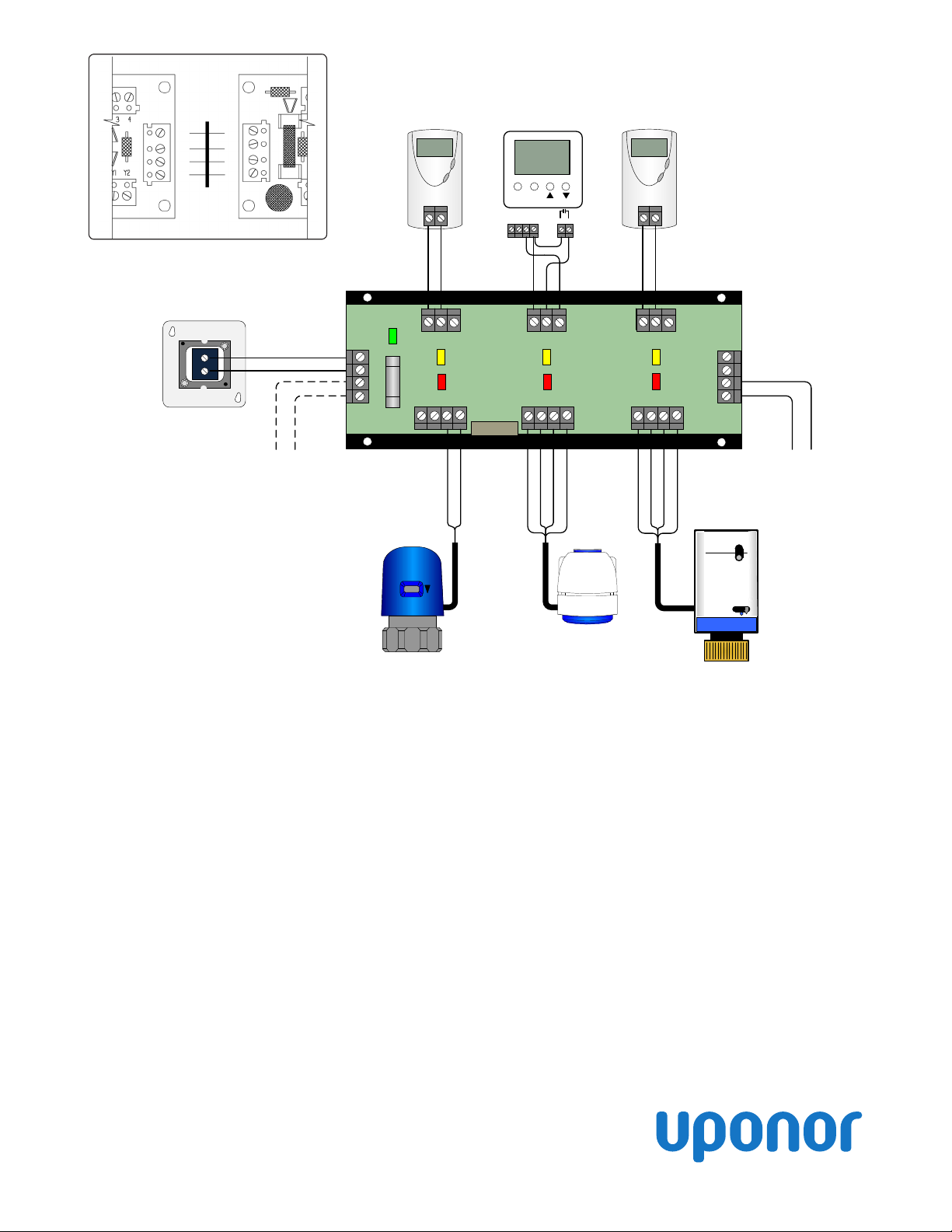
Figure 1: Module Jumper
24 VAC Transformer
A3050050
Figure 2: Wiring Diagram
Alternative wiring
connection to
pump relay, boiler, etc.
A3030522 Two-wire Thermal Actuator (EP)
A3030523 Two-wire Thermal Actuator (TruFLOW
A3020416 Two-wire Thermal Actuator
WRh
2 43
R
C
ES
ES
R 1 R2 Y1 Y2
Brown Wire
Menu Item
C RCom S1
5 6
2 43 2 43
R 1 R 2 Y 1 Y2 R 1 R2 Y1 Y2
Blue Wire
Red Wires
Yellow Wires
A3010522 Four-wire Thermal Actuator
3
⁄4" Zone Valve
A3010525
A3010526 1" Zone Valve
TM
)
WRh
R
C
ES
ES
Red Wires
Yelow Wires
A3020522 Four-wire MVA
3
⁄4" MVA Zone Valve
A3070525
A3070526 1" MVA Zone Valve
To Pump Relay, Boiler, etc.
ZoneCtrlMdl_IS_H300_0113, Copyright © 2013 Uponor, Inc. Printed in the United States
Operation
Power Up
The Power LED must be illuminated
Green for the Zone Control Module
to operate properly. If the Power
LED is not illuminated Green,
check the supply power (transformer)
and wiring.
Call for Heating
If a compatible thermostat calls for
heat, the LED below the terminal
block for that thermostat turns Yellow
(signaling the thermostat is on).
• If two-wire actuators are
connected, the associated LED will
begin to flash Red then turn solid
Red after 3 minutes.
Uponor, Inc.
5925 148th Street West
Apple Valley, MN 55124 USA
Tel: 800.321.4739
Fax: 952.891.2008
• If four-wire actuators are
connected, the associated LED will
begin to flash Red then turn solid
Red when the end switch closes.
Once the LED is on and lit solid
Red, the relay for ES terminals will
close, enabling a pump, boiler or
other heating component.
Ending a Call for Heating
If a compatible thermostat no longer
requires heat, the LED below the
terminal block for that thermostat
will turn off.
• Power will be removed from the Y1
and Y2 terminals, allowing the
actuator(s) to close.
Uponor Ltd.
2000 Argentia Rd., Plaza 1, Ste. 200
Mississauga, ON L5N 1W1 CANADA
Tel: 888.994.7726
Fax: 800.638.9517
• The Red LED will flash, indicating
the call for heat on that zone has
been removed and the actuator(s)
are closing.
• If using a fast-opening motor (e.g.,
a Motorized Valve Actuator), the
Red LED will turn off as soon as
the end switch opens.
The relay for ES terminals will open
when there are no Yellow LEDs lit
on the board (or boards if they are
ganged together).
www.uponorpro.com
 Loading...