

Page 1

netTV3 System
User Guide
Includes hardware installation,
management tools and software
configuration for netTV3 System
Page 2

Contents
INTRODUCTION.......................................................................................................................................3
INSTALLATION........................................................................................................................................4
Connection..........................................................................................................................................4
Configuration......................................................................................................................................6
MANAGEMENT......................................................................................................................................11
File......................................................................................................................................................12
Account..............................................................................................................................................14
T1........................................................................................................................................................17
T2........................................................................................................................................................19
About.................................................................................................................................................21
TEST TOOL.............................................................................................................................................22
CLIENT PLAYER....................................................................................................................................24
Windows App....................................................................................................................................24
Mac App............................................................................................................................................30
Mobile App........................................................................................................................................33
IPTV STB............................................................................................................................................37
Page 3

INTRODUCTION
The netTV3 System platform consists of the following elements:
§ Content Management System (CMS) — T1Box
T1Box is a system on chip (SoC) base device that integrated Account Manage and Content
Distribution functions. It uses the redundant structure to divide into main and backup. Generally,
backup is in standby status and does no work, and all the work is done by main. When main can't
provide service , backup will enable and provide the same service to take the place of main
temporarily until main restores its functionality.
§ Media Sever (Head-End) — T2Box
T2Box is also a system on chip device that integrated dual tuner, 2 channels H.264 encoder and
content delivery functions.
§ Client Player
netTV3 System provides multi-platform Player to meet the needs of a variety of device.
Customer can use the computer, smart phone, tablet and STB to enjoy watching TV.
Page 4

INSTALLATION
Connection
T1 Connection
Connect to network
Connect the ETHERNET port to the corresponding port on your Modem or Router using
the Ethernet cable.
When the NET indicator on the front panel is red, it means LAN functionality is enabled.
When it is green, either WAN or WAN+LAN functionality is enabled.
Connect Power Source
(Remember to place the step at last.)
Connect the supplied power adapter to the port labeled DC5.5V, and plug the power
adapter into an electrical outlet.
When T1 starting up, the PWR indicator on the front panel will turn green.
Page 5

T2 Connection
Connect cable or antenna
Connect the Coaxial/RF cable to the Antenna IN of T2.
Connect to network
Connect the ETHERNET port to the corresponding port on your Modem or Router using
the Ethernet cable.
When the NET indicator on the front panel is red, it means LAN functionality is enabled.
When it is green, either WAN or WAN+LAN functionality is enabled.
Connect Power Source
(Remember to place the step at last.)
Connect the supplied power adapter to the port labeled DC5.5V, and plug the power
adapter into an electrical outlet.
When T2 starting up, the PWR indicator on the front panel will turn green.
Page 6

Configuration
Before configuration you have to make sure that your PC and your T1 or T2 are connected to the
same router. If your network configuration mode is PPPoE and there is no router, please use the
Ethernet cable to connect your T1 or T2 and PC directly.
T1 Configuration
1. If your network mode is PPPoE, please skip Step 1. If it is Dynamic or Static IP, please login the
corresponding router to add four virtual server ports first.
Enter the router’s “Virtual Servers” page, and click the “Add New” button to add the service ports
3512/80/3514/3515 for T1 as following. Type the T1 IP Address in the IP Address field. The
protocols of ports 3512/80 are “UDP” and ports 3514/3515 is “TCP”.
Then it will display as following. You can use the management tool to diagnose if these four
ports can work normally.
✍
Port 3512/UDP is used for communication with T2;
Port 80/UDP is used for communication with Client;
Port 3514/TCP is used for communication with Main T1 (only available for Backup T1);
Port 3515/TCP is used for T1 login and management.
Page 7

is connected to a cable modem or
router, and network configuration is dynamic
“Static IP” and enter the static IP information
✍
If your network mode is Dynamic IP, you can
skip the following Step 2 ~ 6 and use T1 directly.
2. Double click the “ ” icon to start the
Configuration Tool net_Setup on your PC.
3. Select “T1 Network Configuration” as the
right picture, click “Next” to forward to the
next step.
4. Then enter the ID and password of T1 to
login and go to the network configuration
page.
5. There are three network connection types:
Dynamic IP, Static IP and PPPoE.
Dynamic IP:
If your T1
IP (DHCP). This is the same as default, so
you can skip the network setting steps and
use T1 directly.
Static IP:
If you are given a fixed IP, please select
provided by your ISP in the below blank
column, such as IP Address, Subnet Mask,
Default Gateway and DNS.
PPPOE:
If your ISP uses PPPoE protocol for Internet access, please select “PPPoE” and enter the
account and password provided by ISP.
Please select one of them to configure T1 according to your network type and click “Finish”.
Then T1 will restart for the configuration to take effect.
The NET indicator will become green if you set successfully.
6. If you select PPPoE, you have to plug out the Ethernet cable from PC and reconnect it to the
ADSL Modem, then replug the T1’s power. Please notice the order of the two steps: Connect
Ethernet cable first, then plug on the power.
Page 8

Select a T2 and
is connected to a cable modem or
and network configuration is dynamic
“Static IP” and enter the static IP information
search
T2 Cofiguration
1. Double click the “ ” icon to start
net_Setup.
2. Select “T2 Network Configuration” as the
right picture, click “Next” to forward to the
next step.
3. Then it will search T2 that have been under
the same Router, it will list the IP & MAC
Address of the searched T2.
click “Next” to go to the network
configuration page.
Note: If your T2 and PC are not under the
same LAN network, you can’t search out it.
4. There are four network connection types:
Dynamic IP, Static IP, PPPoE and WiFi.
Please select one of them to configure T2
according to your network type.
Dynamic IP:
If your T2
router,
IP (DHCP). This is the same as default, so
you can skip the network setting steps and
use T2 directly.
Static IP:
If you are given a fixed IP, please select
provided by your ISP in the below blank
column, such as IP Address, Subnet Mask,
Default Gateway and DNS.
PPPOE:
If your ISP uses PPPoE protocol for Internet access, please select “PPPoE” and enter the
account and password provided by ISP.
WiFi:
If your T2 is connected to the specified USB wireless adapter, please select “WiFi”. It will
the available wireless networks. The network name (SSID) and security setting (Open network
or Secured) of detected WiFi networks are displayed in the WiFi network section.
5. Port Forwarding: The default setting is UPnP Auto. If the effect of automatic port isn’t satisfying,
you can set AV port for yourself.
If the router supports UPnP, please don’t select DMZ or Virtual Server. If you select the item you
have to enter the corresponding ports in the following fields when set to DMZ or Virtual Server.
(Please refer to instructions of router.)
Page 9

6. If you select PPPoE, you have to plug out the Ethernet cable from PC and reconnect it to the
ADSL Modem, then replug the T2’s power. Please notice the order of the two steps: Connect
Ethernet cable first, then plug on the power.
7. T2 will reboot automatically for the network configuration to take effect. The NET indicator will
become green if you set successfully. And if the NET indicator is still red or off after 10 minutes,
please refer to the following instructions.
If the NET indicator is off or red, T2 can’t be
connected by internet. Please follow the steps below
for easy network troubles solution.
NET indicator is off:
1). Check if the two indicators of RJ-45 Ethernet
connector light green. If not please confirm that the
Ethernet cable and network device (modem or
router) are available.
2). If the connection type is PPPoE, please check if
the input account and password are correct. Then
check if the modem and telephone circuit are
available.
3). If the connection type is WiFi, you should confirm
that the wireless signal strength is at lease 3 bands
(full bands best). If not please decrease the distance
between T2 and wireless router.
And if the router is secured, please check if the input
key is correct. If the key is incorrect, you have to
reset T2 first.
NET indicator is red:
This status means that LAN connection is available,
but the connected router can’t forward ports which
T2 request to internet. Because T2 forwards ports by
UPnP as default, so you should check if the router’s
UPnP function is available.
Please connect PC and T2 to the same router, then
run net_Setup and select “UPnP Function Testing”,
and then click the “Test” button to start testing.
>> Test result: Doesn’t support UPnP
1). Enter into the router settings page and enable the
UPnP function (as right figure).
2). If the router doesn’t support UPnP, please use
DMZ or virtual server instead.
Page 10

will reboot and waiting
Assistance Service Settings item will change
>> Test result: Supports UPnP
1). If the router’s UPnP function of is enabled, please
try to disable it and enable again. Then unplug the
power adapter of T2 and plug it again.
2). If there is another router on front of the connected
router, this is second grade router configuration (as
right figure). The configuration can’t forward the
requested ports to internet successfully, so you have
to remove one of the two routers to use T2.
8. If the network equipment which T2 connected is a router, and the computers that connected to
the same router can access to the web, just T2 can't go online via internet, you can use the
remote assistance service for help.
This situation may be because that router can’t transfer the connection ports that T2 needs, and
then you must set the router to configure these connection ports. If you don’t know how to set,
you can enable the remote assistance service and let the professional personnel help to set it.
Start net_Setup and select “T2 Remote
Assistance Settings Service”, then it will
search and list T2 that have been
connected.
Then select the T2 you want set and then
click “Next” directly to forward to the setting
page.
Select “Enable”, then enter the Assistance
service key, Router’s login account and
Router’s login password, and your phone
number.
The Assistance service key is a string with
10 characters. You can get it from your
operator.
Click “Finish” then T2
for the assistance service settings.
When the assist personnel complete the
remote assistance settings, the Remote
to Disable, then T2 will reboot for the
changes to take effect.
Page 11

Account
MANAGEMENT
T1_Manager is a system management tool which is used to view and manage all account, CH
Table and T2 information. And it has to be connected to T1 to realize its functions.
Double click the “ ” icon to start T1_Manager, the main menu after login is as following:
File
T1 T2
Edit CH Table Show All Accounts Modify T1 Password Show All T2Boxes
Backup Edit Account Reboot T1 Search the Specified T2
Restore Search the Specified Account Diagnose T1 Reboot the Selected T2
Export Specify an Account to Quit Custom Distribution Show T2 Total Number
Login/Logout Show T1 Version Show T2 Usage Ratio
Exit
Page 12

File
Edit CH Table
Select a CH Table to edit, there are 9 CH tables for you to edit. These CH tables are used to
distribute to different accounts.
The left channel list is fixed to the default channel table, and the right list is the current CH Table.
You can only edit the right mapping relation. When a channel is set as “0” it means that channel will
not appeared on TV video.
Backup
This item is used to backup account formation or CH table for restoring when necessary, and the
backup files can’t be opened by other applications. The backup files will be saved in the “Backup”
folder under the installation folder as default.
The file extension name of backup account file is “act”, and the account file is “cht”.
Page 13

Restore
This item is used to restore the backup account and CH Table. Select the backup file and click
“Open” to restore. Then the current account and CH Table setting will be repeated by the backup
files, so please use the function with caution.
Export
Using this item you can export the account and CH Table files to Excel format.
Click the item and select the destination folder, then it can export the account information or CH
table to the folder.
Page 14

Login/Logout
Before management you have to login T1 first. Enter the ID and password of your T1 in the dialog
then click “Login” to login and operate.
You can also click this item to logout when in login status.
Exit
Exit T1_Manager.
Account
Show All Accounts
This item will list the information all account, such as ID & password, Activity, CH Table and Expiry.
Remote users can use these account ID & password to login and watch TV.
The detailed descriptions of each item are in the last page. Double-click an account can edit it.
Page 15

Edit Account
This item is used to edit the selected account for operator. Select an account in the account list and
click the “Edit” menu, it will pop up the account edit window as right.
Active
No.
ID
Password
CH Table
Test account
Reset
Test days
Enable or disable the account.
Account number.
Account login ID.
Account login password.
There are 10 CH tables for select, each can set different channel. CH table
1 is the default. The other nine CH Tables can be edited in the File menu.
Operator can select one of them for an account and then the account can
use the account ID and password to watch the corresponding channels of
that CH Table.
Set the account as test account. Then the account will only be available in
the specified test days after user first login.
If the test account has been used, operator can check this item to return it to
unused status, and the test duration will also return to the preset test days
before.
The available days of test account. After user logins the test account for the
first time, the test days will decrease with time.
User Expiry
Operator Expiry
Comment
When operator set the User Expiry, user can only watch TV before both the
operator expiry and user expiry.
Account operator expiry (fixed). The account is only available before the
operator expiry.
Account comment, limited to 18 characters.
Page 16

Search the Specified Account
This item is used to search a specified account. Enter the account ID and then click “OK” button to
search it in all accounts list.
Specify an Account to Quit
If you want to disconnect a specified account, you can use this item. Then it will pop up a dialog for
you to type the account ID, after confirm the account will be quitted.
Page 17

T1
Modify T1 Password
This item is used to modify T1’s login password for net-gaTV tools, T1_Manager, net_Setup and
T2_Tester.
Reboot T1
Using this item can reboot T1 when necessary. Then T1 will restart and T1_Manager will quit
automatically.
Diagnose T1
Using this item can test if the communication ports 3512/80/3514 can work normally.
Port 3514 is used for communication with Main T1, so it only diagnoses this port when the current
T1 is Backup T1.
Custom Distribution
Using this item can set the distribution priority for each T2 under the current T1. When remote users
send connection request, T1 will distribute T2 in order of priority for users to connect. This function
will be unavailable if there is no T2 connected to T1.
You can also disable the custom distribution and use default distribution directly.
It will distribute all Tuner A first according to the priority and then Tuner B. For example, there are
three T2 and their priority order is T2(1), T2(2) and T2(3), then the connection order will be as
following:
Page 18

1st user
2nd user
3rd user
Tuner A of T2 (1)
Tuner A of T2 (2)
Tuner A of T2 (3)
4th user
5th user
6th user
Tuner B of T2 (1)
Tuner B of T2 (2)
Tuner B of T2 (3)
Enable custom
distribution
No.
RTSP
MAC
IP
Status
Clear (button)
Backup (button)
Restore (button)
Export (button)
Enable the custom distribution. When disabled, it will use the default
distribution, but the custom distribution list will be also displayed in the page.
Priority number. You can double click it and type new priority number to
change that T2 priority. T2 with high priority will be gave top priority when
connection.
T2 RTSP port.
T2 MAC address.
T2 IP address.
Show T2 current status, online of offline.
Clear the current custom distribution list, and then it will display the default
distribution order.
Export the current custom distribution list to the “Backup” folder. The file
extension name is “cus”.
Restore the backup custom distribution list.
Export the custom distribution list to Excel format.
Page 19

Show T1 Version
Show T1 version and T1 firmware compile time here.
T2
Show All T2Boxes
This item will list all T2Boxes’ Tuners under this T1. It displays their IP & MAC address, RTSP port
and usage status.
No.
RTSP
MAC
IP
Tuner
Tuner number.
T2 RTSP port.
T2 MAC address.
T2 IP address.
This column is used to discriminate the two Tuners of T2. “1” means Tuner A and
“2” means Tuner B.
You can also discriminate them by the last character of MAC address. The
character “A” means Tuner A and “B” means Tuner B.
ID
Status
The column is only available when the corresponding T2 is busy, and then it will
show the account ID which is connecting that T2.
Show T2 current status.
Page 20

Search the Specified T2
This item is used to search the specified T2. Enter the corresponding information and then click
“OK” button to search the specified T2.
You can search T2 by the connected account ID, by RTSP Port or by MAC address.
Search by ID
Search T2 by the account ID which is connected T2 currently. So it will only
search in the T2 with busy status.
Search by Port
Search by MAC
Search T2 by RTSP port. It will list all the T2 with the specified RTSP port.
Search T2 by MAC address.
Reboot the Selected T2
Using this item can reboot the current selected T2 when necessary.
Show T2 Total Number
This item can display current T2 usage status, such as T2 total number, Tuner total number and
free Tuner number.
Page 21

Show T2 Usage Ratio
This item shows T2 usage ratio (Max number of used Tuners / Tuner total number), the Tuner
usage situation when there are max online users. You can adjust T2 or accounts to make the best
use of netTV3 System according the usage ratio.
When the max used Tuners number is equal to Tuner total number, it means that all Tuners have
ever been used. Please note if they are not enough.
Please click the “Clear” button If you want to clear the T2 usage ratio record. And then it will start to
count the usage ratio from now on.
About
About T1_Manager
Show the firmware information such as T1_Manager version.
Page 22

TEST TOOL
T2_Tester is a test tool which is used to search the online and idle T2 to connect and test via T1. It's
aimed primarily at network speed and video quality. The test results can be used as reference to
adjust T2Box's network and video signal to reach acceptance level for administrator.
When testing, T1_Tester will connect all T2 under the specified T1 and record the specified three
channels of their Tuners (each channel 30S). And then you can play the recoded files later to
assess your network condition.
Double click the icon “ ” to start T2_Tester. The main panel is as following (you can click “ ”
button to hide or display the test panel).
Page 23

Recording Test
Use this item to record all T2 Tuners under the
specified T1.
Select “Recording Test” in the Test Operation.
Input T1 ID and password and specify the three
channels to be tested, and then click the “Start”
button to begin to test.
Then it will record the three channels of all
Tuners under this T1 one by one. Each Tuner
will have a private recorded file with 90S length
(each channel 30S).
The recorded files are saved in the “Record”
folder as default.
✍
§ The recorded file’s name consists of T2 MAC and the character “A” or “B”. You can get T2 MAC
address on the sticker labeled at the bottom of T2Box unit. The last character “A” means Tuner A
and “B” means Tuner B.
§ If a Tuner is being connected when test, the application will skip it and test next one. And it will
return to record it after all other Tuners have been recorded. It will wait until the user quits, so we
suggest you test T2 when there are fewer users online.
Specify a Tuner to Watch
Use this item to connect the specified Tuner and
watch its TV programs.
Select “Recording Test” in the Test Operation.
Input T1 ID and password, then enter T2 MAC
and select Tuner (Tuner A or Tuner B), and then
click the “Login” button to connect and watch it.
When watching, you can click the “ ” button to
record the current program.
Play Recorded Files
After Recording Test, you should play the
recorded files to assess the T2 network speed.
Select “Play Recorded Files”, It will list all
Tuners’ recorded files in the right PlayList and
automatically play them in the video area. You
can assess the network conditions according the
recorded files’ video quality.
Page 24
CLIENT PLAYER
Windows App
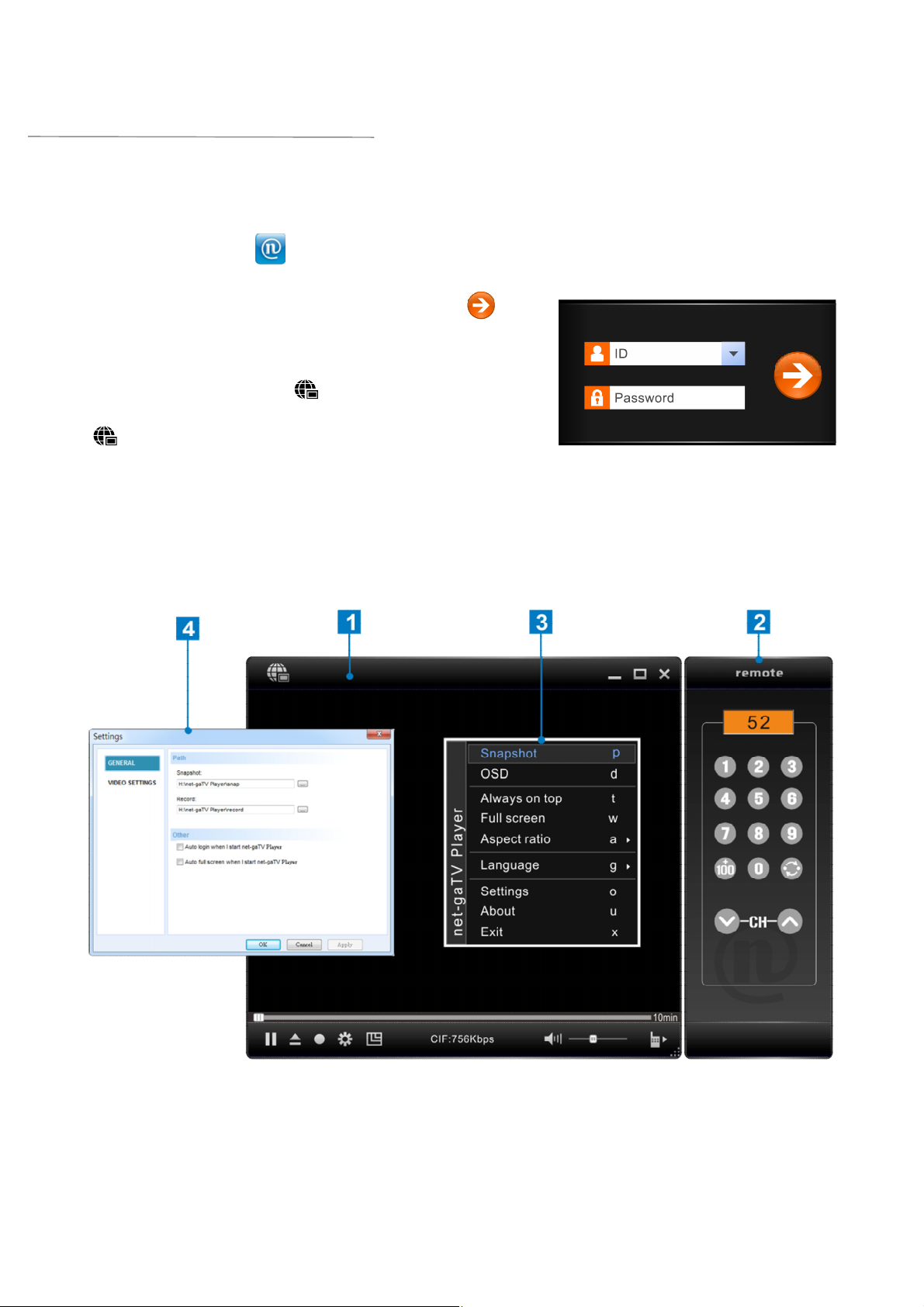
Login
Double click the icon “ ” on your desktop to start net-gaTV Player.
The login window is attached to the center of the player window.
Enter the account ID and Password and click the “ ”
button to build up connection. You can get them in the
account list of management tool T1_Manager.
Before login, you can click “ ” in the main panel to hide or
show the login panel. And after login, you can also click
“ ” to logout directly.
Operation Interface
The operation interface of net-gaTV Player includes 4 parts: 1. Main panel including video display
area 2. On-screen remote control panel 3. Right click menu 4. Function setting pages
Page 25

Main Panel Instructions
1
2
3
4
5
6
Items Instructions
Video display area
10min On/Off Time-Shift switch
Login/Logout
Minimize
Full-screen
Close the application
Playback and Time-Shift control slide bar
Playback / Pause
Open the Playlist (Recorded files list)
Instant recording / Pause
Function setting key
Video resolution switch
7
8
Current status display
Mute key and volume control slide bar.
On-screen remote control panel switch.
Page 26

On-Screen Remote Control Panel
Display the current channel number.
0-9 number keys.
+100 key, when you want to switch to the three-figure
channel number, click the key and then click the last
two digits.
Channel return key. You can click it to return to the
last channel.
Last Channel (Channel down, as CH25→CH24).
Next Channel (Channel up, as CH25→CH26).
Right click menu
When you run net-gaTV Player, you could move your mouse cursor and right click to open the
pop-up menus. The commands on this menu are the same with those on the control panel but you
could find some more options.
Items Operations
Capture the still pictures.
Enable or disable channel number display function.
Place the window on top when several windows open.
Display the video full screen.
Select the aspect ratio from Free, 4:3 and Wide Screen.
Select the language from English, Chinese Simplified and
Chinese Traditional.
Open the property settings page.
Show the related system information of the player.
Exit the net-gaTV Player.
Page 27

Mouse and Keyboard Operations
You can perform the following net-gaTV Player operations with your computer’s mouse and
keyboard.
Keyboard operations
Shortcut Key Operations
Shortcut Key Operations
A
B
D
G
L
M
O
P
R
T
U
W
Select the aspect ratio
Pop-up the right-click menu
Enable channel number display
Switch the display language
Return to last channel
Mute or restore sound
Pop-up the property setting page
Capture image
Pop up the remote control panel
Always on top
Show the system information
Full screen
Mouse operations
Items Operations
Rotating the mouse wheel
On a screen, rotating the mouse wheel away from you volume
up, and rotating it towards you volume down.
X
“Home”
“End”
↑
↓
→
←
+
-
(0~9)
“Space Bar”
Exit
Record
Stop recording
Channel up
Channel down
Volume up
Volume down
+100
Brightness up/down
Jump to the monitoring point.
Play/pause(Only take effect
when playing recorded files)
Scroll wheel click
Right click
Mute
Right clicking anywhere inside the window displays a context
menu as described below.
Page 28

Setting Pages
Click the “ ” button to open the function settings page as following.
GENERAL
Snap folder: The directory path to save the captured picture files.
Record folder: The directory path to save the recorded files.
Auto login: When check this item, the application will auto login using the last
successful connection ID and password.
Auto full screen: When check this item, it will auto full screen when start the application.
VIDEO SETTINGS
Resolution: There are three resolutions for you to choose, and the vertical resolutions
have a little difference under different TV system (NTSC/PAL).
Auto Adjust bit rate
When you select the item it will auto adjust the Bit Rate and Frame Rate.
and frame rate:
Video Adjustment: Adjust the Brightness, Contrast, Hue and Saturation. Drag the slide bar to
adjust the value. You can also press the “Default” button to resume to the
default value. It will show adjustment effect preview on the right.
Page 29

Instant Recording
When watching TV programs you can record them and enjoy them later.
1. Press the recording button “ ” to begin to record programs.
While recording, it will display the recording sign on the video display area. The
time means the recorded duration.
2. The recording button will become stop recording button “ ” while recording.
Pressing the “ ” button can stop recording.
✍
You can also click the “ ” button to pause, then the time on the recording sign will pause too.
Pressing the “ ” button again can continue recording.
Time-Shifting
The Time-Shifting function makes it can record the playing program at any time, and you can
continue to watch later, it’s also easy to skip advertisements. So if you need leave the player when
watching program, you can enable the Time-Shifting function, and it will begin to record the
programs automatically, then you can watch the program when get back.
1. Click the “10min” to enable the Time-Shifting function. (It can also disable the Time-Shifting
function.)
2. Then it will begin to record the programs. The blue bar means the recording duration, and you
can drag the slide bar to watch the recorded programs at any time. You can also drag it to the
right of blue bar and watch the live program.
✍
§ When the Time-Shifting function is on, the interval of channel switch will has a longer delay time
(about 3s).
§ The application can only record the programs for 60 minutes, and when it up to 60 minutes, the
first recorded programs will be replaced. So you can only watch the program for the last 60
minutes.
Page 30

Mac App
Installation
Please follow the following steps to complete net-TV 2012 installation on Mac PC:
1. Download the installation folder from http://net-TVBox.dyndns.tv/, then run “net-TV 2012.pkg”.
2. This is the first screen you will see. Click the
“Continue” button to begin the installation, and
then follow the on-screen instructions.
3. Select the disk where you want to install the
application, then click “Continue”.
4. Click the “Install” button to install.
5. After install successfully, click “Close” to exit
the installation wizard.
Page 31

Login
Click the icon “ ” to start the application.
Enter the ID and Password in the login
panel and click the “login” button to build up
connection.
It will remember the ID and password when
you login successfully.
Interface Instructions
The main panel after login is as following:
Page 32

Remote control panel
Open the channel list
Video quality settings key
0~9 channel number keys. Click one or two
channel numbers to switch to the desired channel.
+100 channel select key. When the desired
channel number is a three digit number, click the
key and then click the last two digits can switch
channel quickly.
Next channel (Channel up, as CH33 à CH34)
Last channel (Channel down, as CH34 à CH33)
Channel return, click it to return to last channel.
✍
You can switch channel with the up/down key of your computer’s keyboard.
Quality
Click the “ ” button, it will pop up the
Settings page as right.
You can select the video quality in this page
according to your network condition in the
Quality page.
The quality has three items: CIF, H-D1 and
D1, user can select according to the displayed
bit rate (the default is D1). The application will
remember the quality status and use the
same quality when login next time.
Page 33

lay Store” or “App Store” or “Marketplace” in
Mobile App
Instructions before installation
net-TV mobile2 is a network TV player designed for smart phone and tablet PC users to login to
enjoy programs. It is available for various mobile platforms such as Android, iOS, and Windows
Phone based devices.
Installation
1. Start “P
the application list.
2. Enter the keywords “net-TV mobile2”, and then
press the search button.
3. Press the searched application to install.
Play Store App Store Marketplace
4. When install finished, it will appear the application
icon as right in the installed applications.
net-TV mobile2
Page 34

Login
1. Press net-TV mobile2 icon “ ” to start it.
2. Enter the ID and password in the login page,
then press the “ ” button.
3. When login successfully, you can start to
enjoy the wonderful video programs.
Function reservation.
Open the ID list. It will remember the ID and password when you login successfully. You can
long touch the ID input box to delete the current ID (Android & Windows phone), or open the
ID list and slide on the selected ID until it appears the “ ” button, then press it to delete
the ID (iOS).
Set the application before login (as right).
Video Quality:
The video quality has four items: ECO, CIF,
H-D1 and D1, user can select according to
the bit rate.
Specify a Static IP to Connect:
Function reservation
Media Streaming:
Android media streaming protocol setting. The default media streaming protocol is RTSP, if
your video can’t be displayed normally, you can try to switch it to HTTP Live Streaming.
Note: The function is only available for Android devices running Android OS 4.0 or above.
About net-TV mobile2:
Show the version information of the application.
Page 35

Interface Instructions
The interface after login is as following:
✍
§ When watching programs, you can adjust volume by pressing the volume control buttons of the
mobile phone.
§ Clicking on the video area can hide or display the remote control panel.
§ As following, when the remote control panel is hidden, you can adjust the screen volume and
brightness by dragging up-down on the video display area, and long touch can switch the video
aspect ratio.
Above functions are for Android device only.
Page 36

the
Remote control panel
Open the channel list
Video quality settings key
0~9 channel number keys. Press one or two
channel numbers to switch to the desired channel.
+100 channel select key. When the desired
channel number is a three digit number, press
key and then press the last two digits can switch
channel quickly.
Next channel (Channel up, as CH33 à CH34)
Last channel (Channel down, as CH34 à CH33)
Channel return, press it to return to last channel.
Video quality setting
Press the “ ” button, it will pop up the settings page as
right.
Video Quality
The video quality has four items: ECO, CIF, H-D1 and D1,
user can select according to the displayed bit rate (the
default is CIF). The application will remember the quality
status and use the same quality when login next time.
The resolution and video/audio bit rate of each quality is as
following:
Resolution
Video bit rate
Audio bit rate
ECO CIF H-D1 D1
352x240 352x240 480x352 720x480
128kbps Auto adjustment:128kbps ~ 2Mbps
Fixed: 24kbps
✍
If your mobile device connects internet by using 3G or 4G network which charged by data flow, you
can select ECO to save cost. When select it the bit rate will be limited to 150kbps (as the above
diagram), but it may appear mosaics when the video has a great change (requires higher bit rate).
Page 37

IPTV STB
netTV3 on TV is a Linux base IPTV
ste-top-box(STB) that designed for netTV3
System. When you install an IPTV STB in
house, you can login with the ID & password
you purchased and enjoy TV programs over
the internet with it.
When watching TV, you can set IPTV STB on
screen directly with the supplied remote
control, and the convenient operation let you
operate it easily even if you don't know how to
operate the computer.
✍
§ Although the appearances of netTV3 on TV
and T1Box look similar, their functions and
uses are entirely different.
§ For more detailed instructions, please refer
to the Operating Instructions of IPTV STB.
Page 38

 Loading...