

Page 1
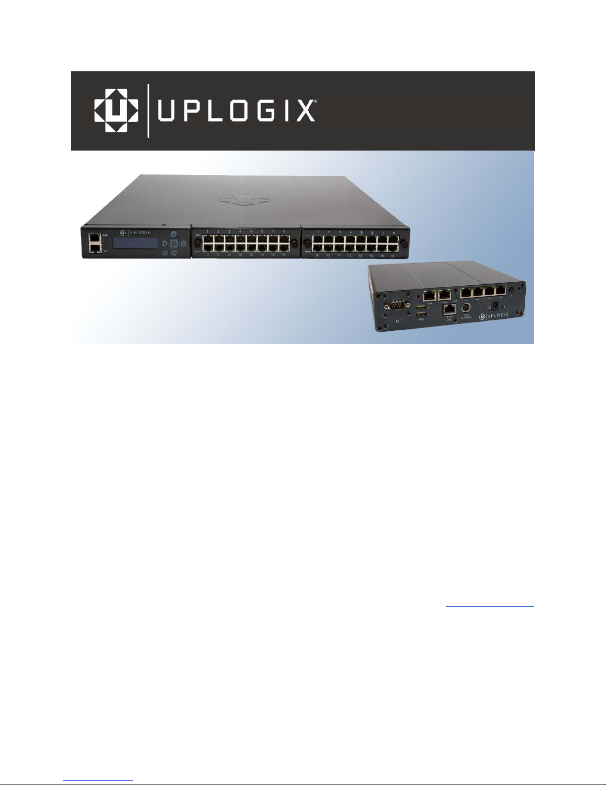
Installation Guide
for Uplogix Secure Remote Management Appliances
Version 3.5
August 2008
UP500027 Rev A
www.uplogix.com
Page 2

Information in this document is subject to change without notice.
© 2008 Uplogix, Inc. All Rights Reserved. Uplogix, the Uplogix logo, and SurgicalRollback are
trademarks of Uplogix, Inc. in the United States and other jurisdictions. All other marks referenced are
those of their respective owners.
Uplogix, Inc.
7600-B North Capital of Texas Highway
Suite 220
Austin, Texas 78731
USA
Page 3

Contents
About this guide..................................................................................................... 1
Target audience.................................................................................................................. 1
Typographical conventions ................................................................................................... 1
Safety summary ................................................................................................................. 2
What's new in this guide ...................................................................................................... 2
Hardware installation............................................................................................. 3
Installing the 32-port Uplogix appliance.................................................................................. 4
Unpacking the shipping box ............................................................................................... 4
Installing the chassis ........................................................................................................ 5
Making connections on the back panel................................................................................. 7
Making connections on the front panel................................................................................. 9
Installing an option card.................................................................................................. 11
Removing an option card that will not be replaced............................................................... 11
Service: Replacing the power supply ................................................................................. 12
Installing the Uplogix 430 appliance ..................................................................................... 13
Unpacking the shipping box ............................................................................................. 13
Installing the chassis ...................................................................................................... 13
Installing the modem or RS-232 module............................................................................ 15
Making the connections required for initial configuration....................................................... 16
Making the remaining connections .................................................................................... 17
Installing the older 4-port Uplogix appliance ......................................................................... 19
Unpacking the shipping box ............................................................................................. 19
Installing the chassis ...................................................................................................... 20
Making connections ........................................................................................................ 21
Installing optional expansion modules ............................................................................... 25
Replacing an expansion module........................................................................................ 27
Removing an expansion module that will not be replaced ..................................................... 27
Quick setup .......................................................................................................... 29
Initial configuration using the keypad................................................................................... 29
Initial configuration via console connection ........................................................................... 32
Configuring the appliance for your LAN.............................................................................. 33
Configuring an optional pulse server.................................................................................. 33
Remote access via the management IP connection................................................................. 34
Locking the keypad and changing the admin password ........................................................... 34
Setting up an appliance to be managed by an Uplogix Control Center ....................................... 35
Creating a placeholder on the Uplogix Control Center (optional) ............................................ 36
Connecting to the Uplogix Control Center from the Uplogix appliance (required) ...................... 38
Support and regulatory information..................................................................... 39
Getting technical support ................................................................................................... 39
Requesting an account.................................................................................................... 39
Requesting support......................................................................................................... 39
Providing comments about this guide................................................................................ 39
Regulatory notices ............................................................................................................ 39
Safety notices................................................................................................................ 39
EMC notices................................................................................................................... 40
RoHS compliance ........................................................................................................... 40
CE Mark R & TTE directive ............................................................................................... 40
iii
Page 4

Contents
Index ................................................................................................................... 41
iv
Page 5
About this guide
This guide describes the procedures for installing, cabling, and provisioning Uplo gix appliances.
Information in this document is subject to change without notice. Please visit
www.uplogix.com/support for the latest updates to Uplogix product documents.
Target audience
This guide is for trained, qualified network support technicians responsible for installing the
equipment.
Typographical conventions
The following conventions are used in this guide.
Sample text from the command line interface is presented in
is presented in
[admin@A101100303]#
admin ssh Mar 22 13:38 (172.30.235.126)
Keyboard characters are enclosed in angle brackets. For example, press <Enter>.
this font. For example:
show who
this font. Text that you enter
Installation Guide for Uplogix Secure Remote Management Appliances 1
Page 6
About this guide
Safety summary
Follow all cautions and warnings to protect the appliance from potential damage or loss of data,
and to ensure your own safety.
Warning: Use the same type of battery when replacing the older 4-port Uplogix appliance’s
lead-acid battery. Using a different type of battery may result in explosion or equipment
damage. Dispose of used batteries according to the instructions.
Caution: Do not store or mount older 4-port Uplogix appliances (blue or white chassis) with
the top cover or front face pointing down. This model uses a lead-acid battery that must not
be placed upside down. Failure to store or mount the appliance correctly may result in
equipment damage.
Caution: Read the installation instructions before you connect the appliance to a power
source.
Read and understand the following instructions before using the appliance:
Only use electrical extension cords with a current rating at least equal to that of the
appliance.
Always disconnect the appliance from power before cleaning and servicing.
Do not spray liquids directly onto the appliance when cleaning. Always apply the li quid first
to a static free cloth.
Do not immerse the appliance in any liquid or place any liquids on it.
Do not disassemble this appliance. To reduce the risk of shock and to maintain the
warranty on the appliance, a qualified technician must perform service or repair work.
Connect this appliance to a grounded outlet.
Only connect the appliance to surge-protected power outlets.
Keep ventilation openings free of any obstructions.
SAVE THESE INSTRUCTIONS.
What's new in this guide
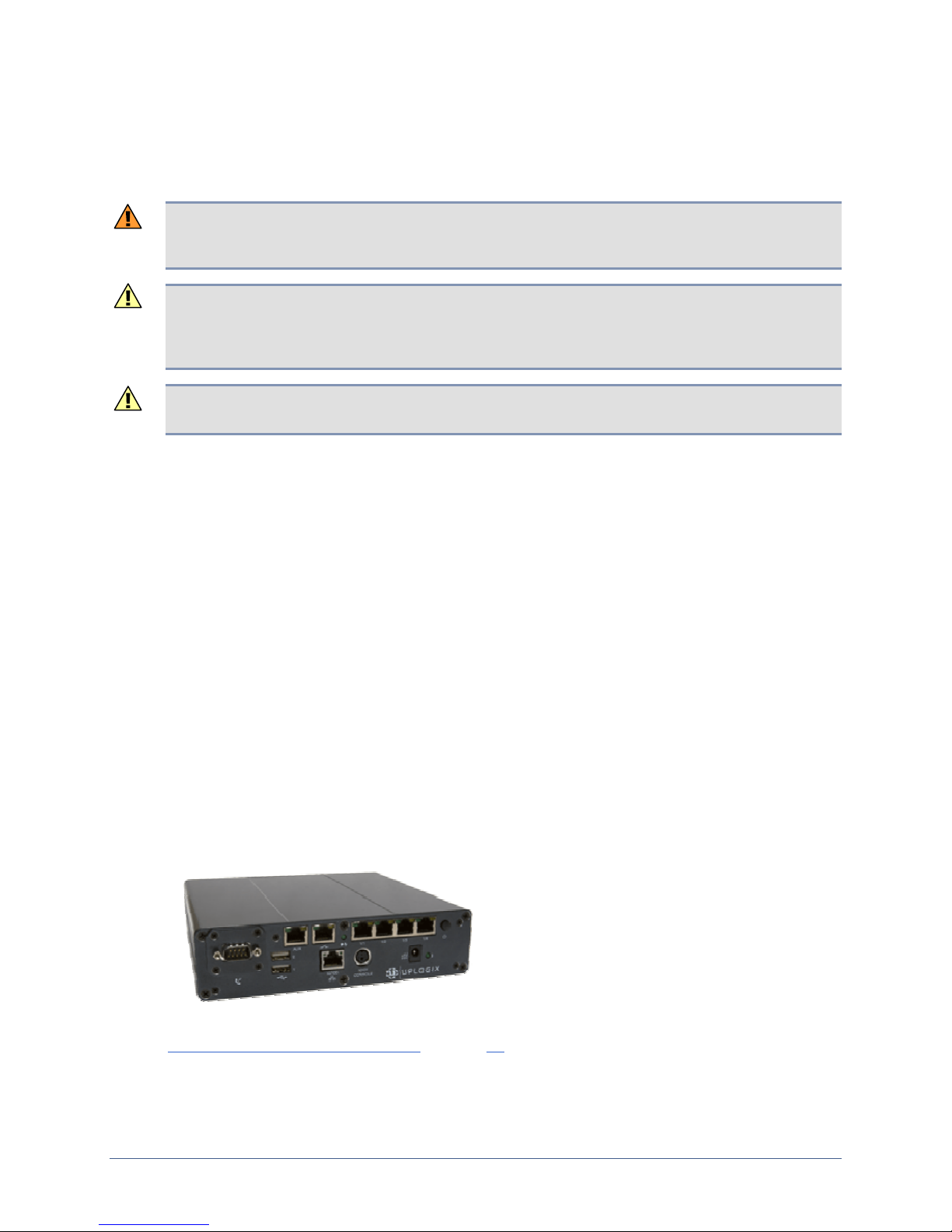
With version 3.5, Uplogix introduces the new Uplogix 430 secure remote management
appliance - a compact 4-port appliance for smaller deployments. Where this product differs
from other models, the differences are noted.
The installation procedure for this product is in the Hardware installation chapter. See
Installing the Uplogix 430 appliance on page 13.
The Uplogix 430 appliance has no front panel display or keypad. Initial configuration is over a
console connection.
2 Installation Guide for Uplogix Secure Remote Management Appliances
Page 7
Hardware installation
Ensure that the power source:
Provides the appropriate line voltage and frequency (100 to 240 V, 50 or 60 Hz)
Provides overload protection
Is connected to earth ground
Warning: The power source must meet all these requirements to ensure safe and reliable
operation.
Ensure that the installation site meets these requirements:
Ambient temperature does not exceed 113° F (45° C)
The site provides at least 3 inches (8 cm) clearance beyond the appliance’s ventilation
openings (if any)
Caution: The unit will overheat if the site does not meet these requirements.
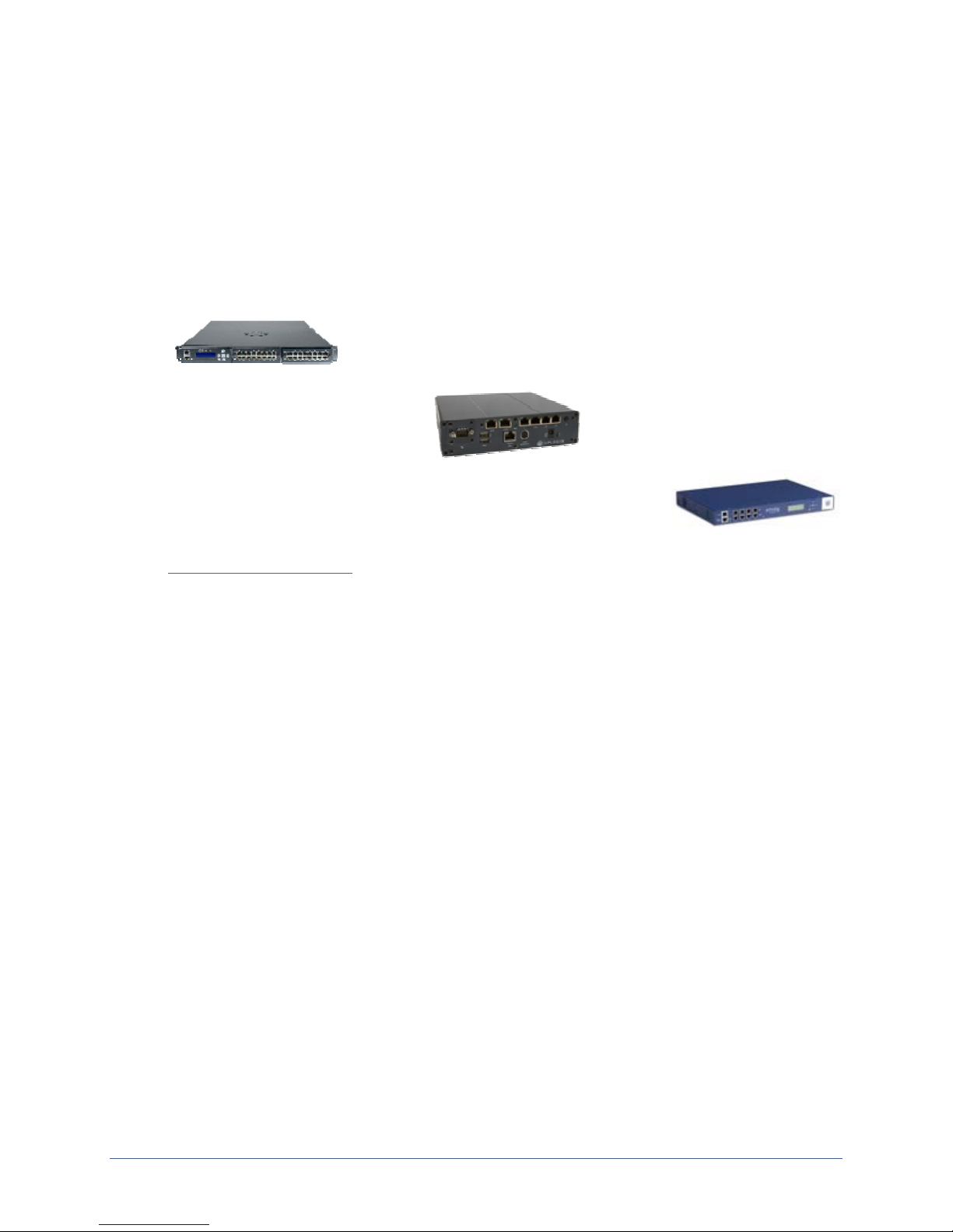
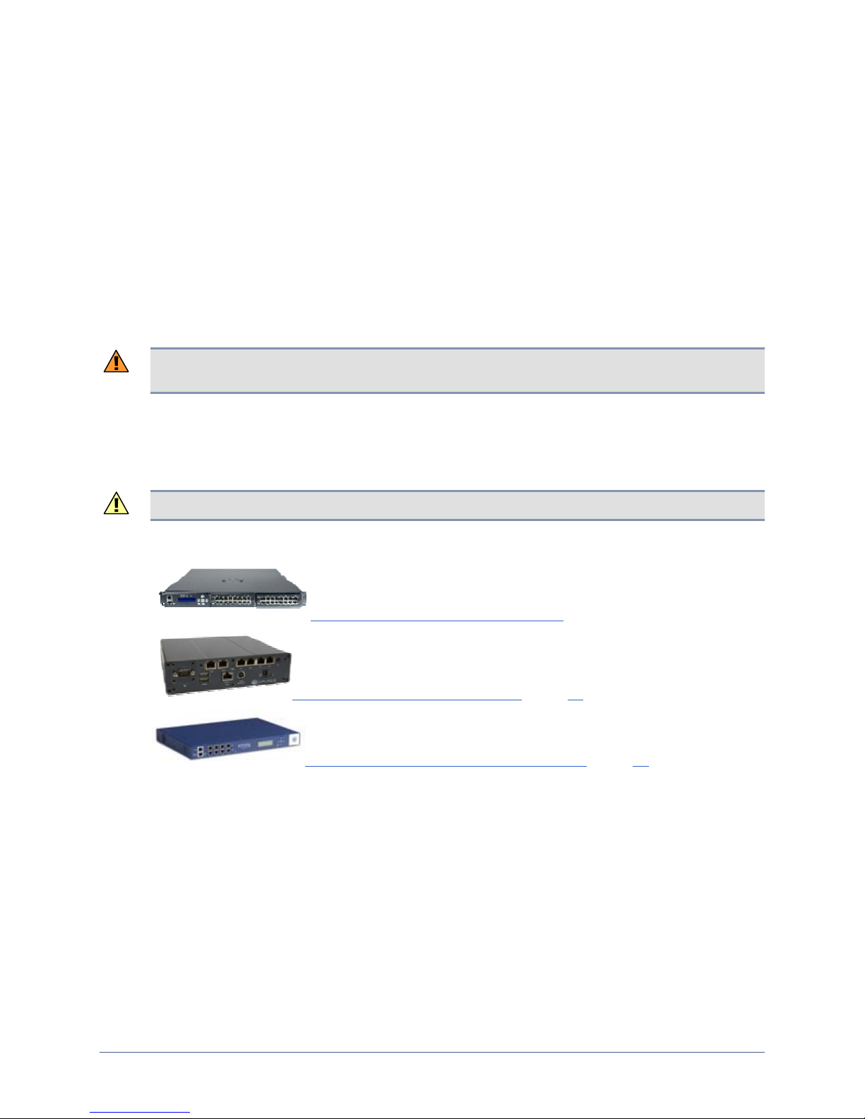
Follow the appropriate installation procedure for the equipment you receive:
Installing the 32-port Uplogix appliance (next page)
Installing the Uplogix 430 appliance (page 13)
Installing the older 4-port Uplogix appliance (page 19)
Installation Guide for Uplogix Secure Remote Management Appliances 3
Page 8
Hardware installation
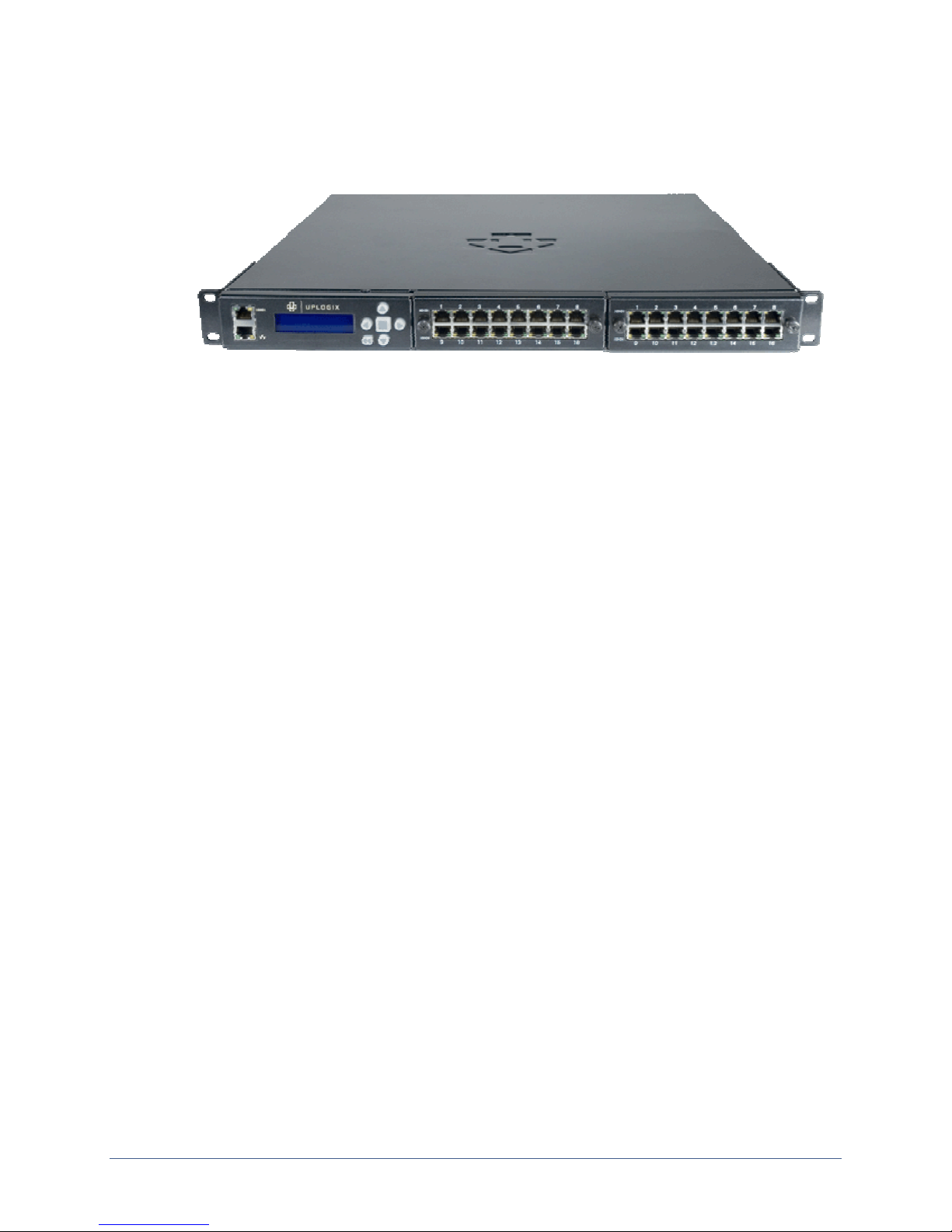
Installing the 32-port Uplogix appliance
This section includes:
Unpacking and physical installation
Making the required connections on the back panel
Making the required connections on the front panel
Installing an additional option card
Service: Replacing the power supply
Unpacking the shipping box
Verify that you have received the following items:
32-port Uplogix secure remote management appliance
Power cord (may be absent if shipped outside the USA)
Rack mounting brackets
Slide rail kit
Screws
Cable kit:
à Cat 5e straight cable, RJ-45, 7 ft. (2.1 m)
à Cat 6 Ethernet crossover cable adapter, RJ-45 M/F
à Phone cable
à DB-9 to RJ-45 adapter
Optional temperature sensor
Installation sheet
4 Installation Guide for Uplogix Secure Remote Management Appliances
Page 9
Installing the chassis
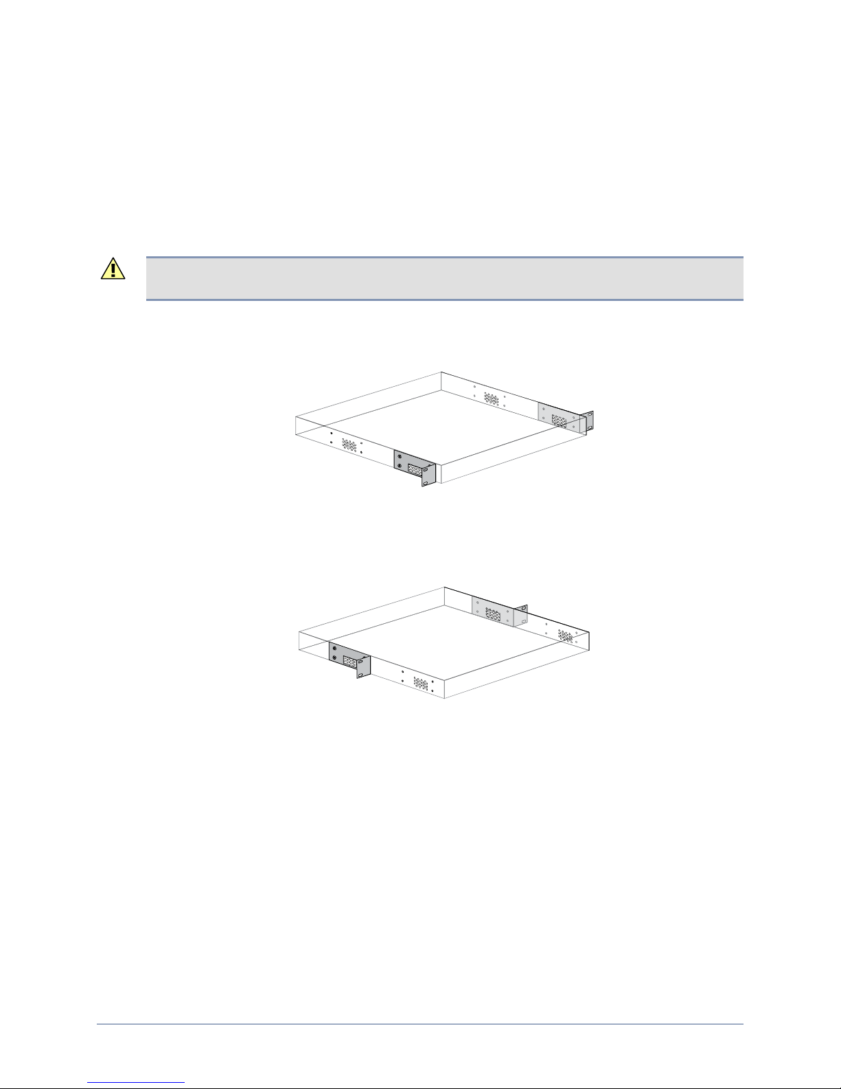
The 32-port appliance is designed for rack mounting using either a two-point or a four-point
mounting system.
Choose one of these mounting methods:
Two-point mount, front attachment
Two-point mount, mid attachment
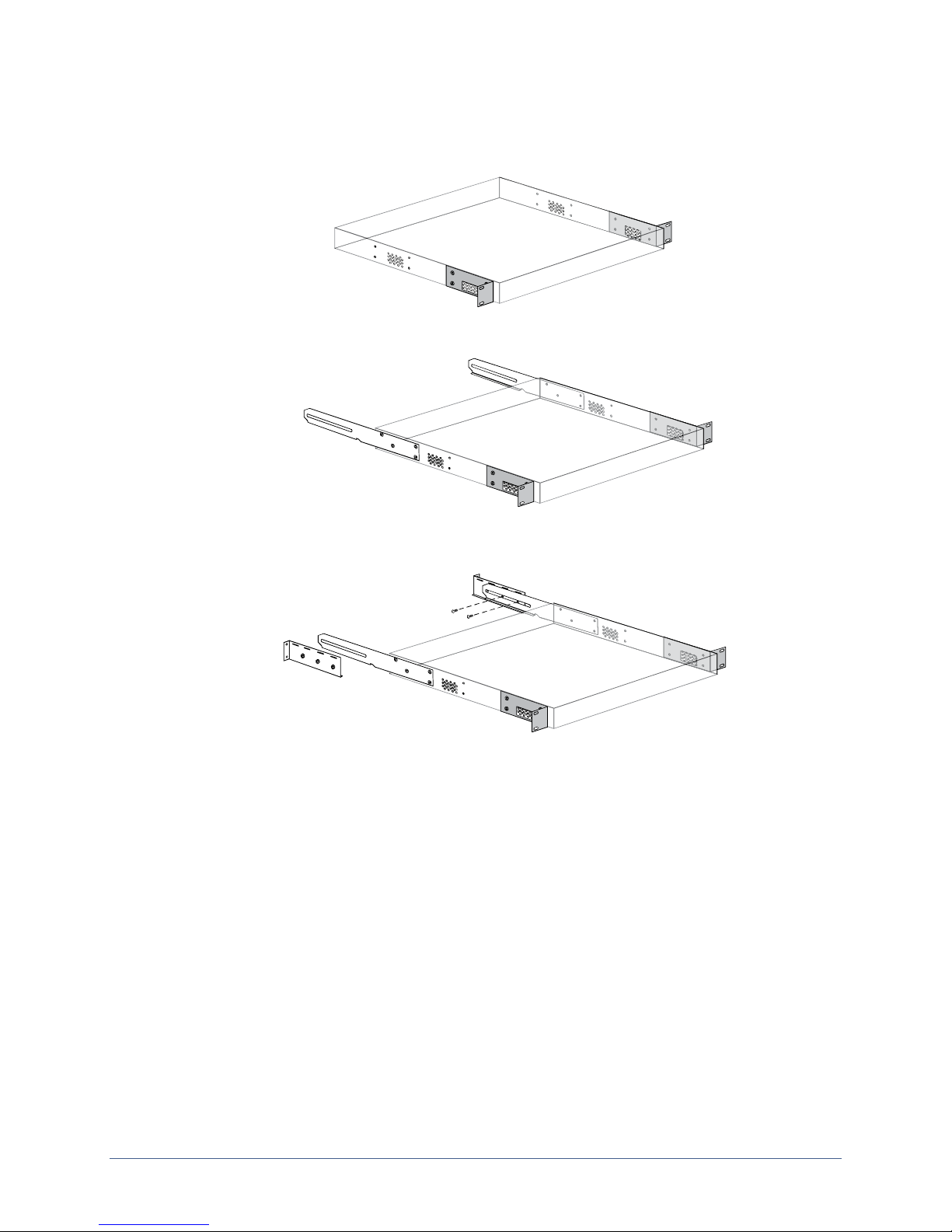
Four-point mount
Caution: Ensure that the openings in the mounting brackets line up with the ventilation
openings in the chassis. If the air flow to the chassis is blocked, the appliance will overheat.
Two-point mount, front attachment
Attach the brackets to the front of the chassis, aligning the openings with the ventilation holes.
Hardware installation
Mount the appliance in the rack.
Two-point mount, mid attachment
Attach the brackets to the chassis midpoints, aligning the openings with the ventilation holes.
Mount the appliance in the rack.
Installation Guide for Uplogix Secure Remote Management Appliances 5
Page 10
Hardware installation
Four-point mount
Attach the brackets to the front of the chassis, aligning the openings with the ventilation holes.
Attach the rails to the sides of the chassis.
Attach the mounting brackets to the rack, and to the rails. You must use at least two screws
on each side.
Mount the appliance in the rack.
6 Installation Guide for Uplogix Secure Remote Management Appliances
Page 11
Making connections on the back panel
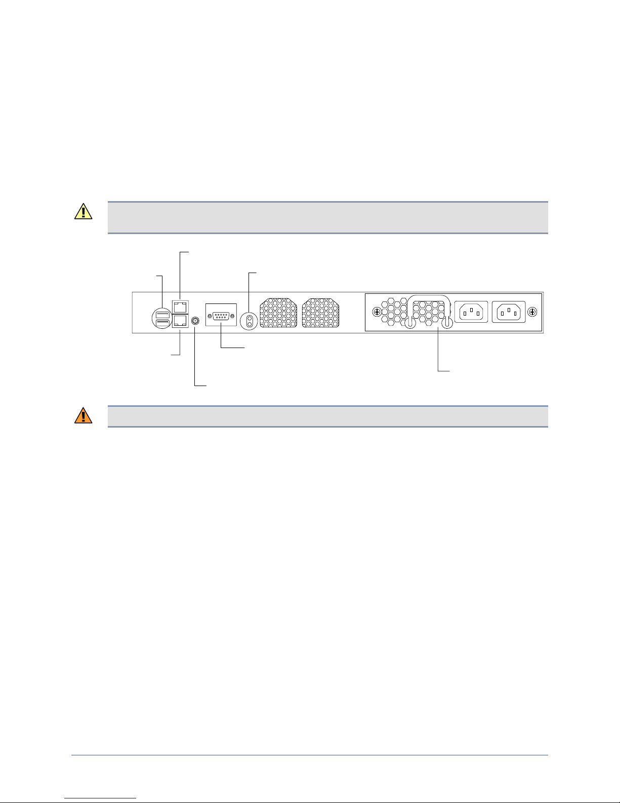
Back panel connections include:
Power
Power controller
Temperature sensor
Modem
Optional hardware authenticator
Connecting power
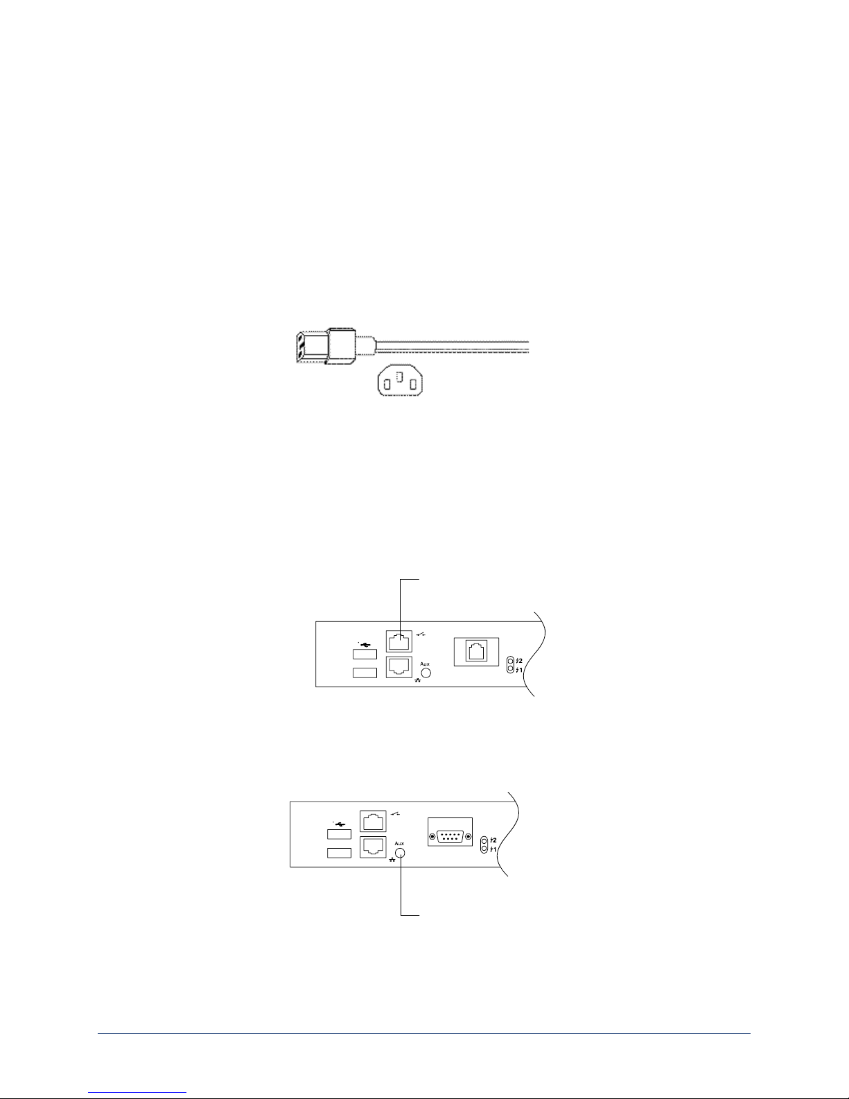
The appliance uses a power cord with a standard IEC-320-C13 female cord end.
Connect the power cord or cords to the unit and to appropriate power sources, then power on
the unit. The display and keypad on the front panel illuminate. As the appliance boots, it
displays progress messages.
Hardware installation
At the end of the boot sequence, it displays the message
Uplogix status good.
Connecting a power controller
Connect the power controller's serial port to the power controller port on the back panel of the
32-port appliance.
Connect power controller
Installing the optional temperature sensor
Secure the temperature sensor’s threaded connector to the 1-Wire® connector on the back of
the chassis.
Route the wire to the desired sensor location (for example, one of the posts on the rack) and
secure the sensor.
Installation Guide for Uplogix Secure Remote Management Appliances 7
Connect temperature sensor
Page 12
Hardware installation
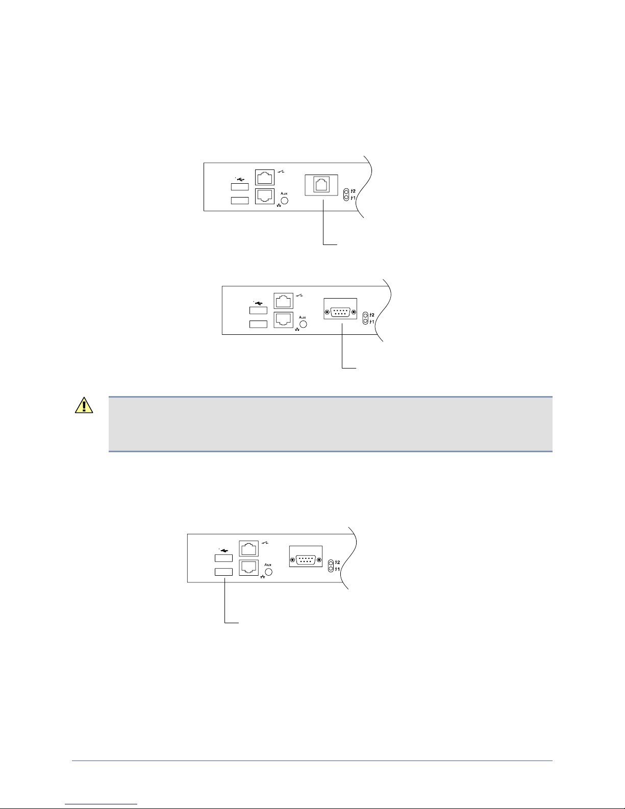
Connecting the modem
This model is available with either an internal modem or a serial port for an external modem.
Connect the internal modem to a standard analog (POTS) phone line provided by your local
telephone company for out-of-band dial-up support, or connect the modem port to an external
modem.
Connect internal modem
to POTS line
Connect to
external modem
Caution: To prevent equipment damage, do not connect the internal modem to digital PBX
systems, VoIP analog terminal adapters, or cellular modems. It is designed for use with analog
telephone lines only. Uplogix is not responsible for damage caused from attachi ng the modem
to a digital phone switch.
Optional: Connecting a hardware authenticator
For automatic one-time password authentication during out-of-band operation, connect an
RSA® SecurID® SID800 hardware authenticator to one of the USB ports on the back of the
chassis.
Connect RSA® SecurID® hardware authenticator
(either USB port)
8 Installation Guide for Uplogix Secure Remote Management Appliances
Page 13
Making connections on the front panel
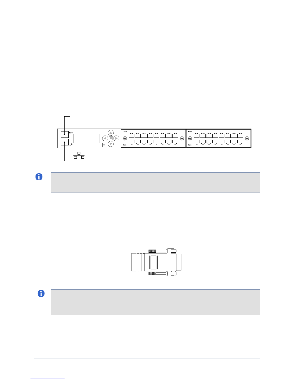
Front panel connections include:
Management Ethernet
Management console
Devices to be managed
Making the management Ethernet and console connections
To manage the 32-port appliance and attached devices in-band through the network, connect
the management Ethernet port on the front panel to your Ethernet network. Speed and
duplexing default to autonegotiation.
IOIOI
Connect to the console workstation’s serial port
for out-of-band management
Hardware installation
21
109
Connect to the network for in-band management
876543
161514131211
21
109
876543
161514131211
Note: After you power on the appliance, one of the indicators on the RJ-45 Ethernet port will
light when low-level connectivity is established. If after connecting this port, both indicators
remain dark, try combining the crossover dongle to one side of the connection.
You may wish to make a secondary management Ethernet connection through the Aux port
on the back of the appliance, below the power controller connector. The main and secondary
management Ethernet connections must be on the same subnet, but can be through separate
switches for redundancy. If you are working with a later model appliance that was shipped
before mid-November 2007, this capability may be unavailable.
To manage the appliance and attached devices using the TTY console, connect the RJ-45 to
DB-9 adapter to your computer’s serial port, and connect the RJ-45 cable from the appliance
to the adapter.
The default settings for the console port are 9600, 8, N, 1.
Note: Link status is indicated by one of the LEDs on the RJ-45 Serial port. If neither light
glows after connecting a device using one of the supplied white Cat 5e cables, the port should
be changed to use DTE. The rolled console cables (often flat) provided with network devices
usually require this change as well.
Installation Guide for Uplogix Secure Remote Management Appliances 9
Page 14
Hardware installation
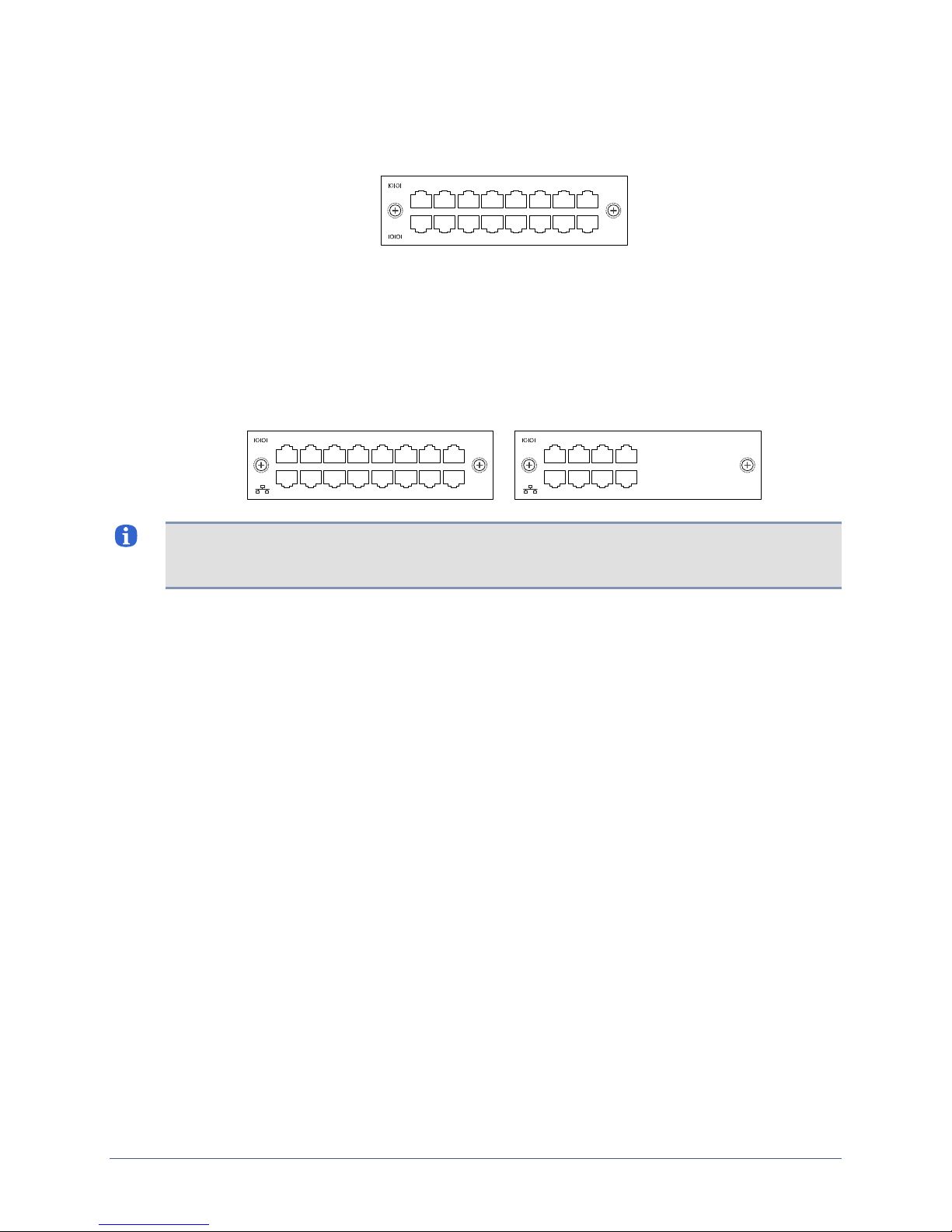
Connecting managed devices to a serial-only option card
Connect the console ports of up to 16 network devices to the 16 serial ports on the option card.
21
109
876543
161514131211
Connecting managed devices to a serial plus Ethernet option card
Use the upper row of serial ports (labeled with the serial symbol) to connect to device console
ports.
To provide for dedicated TCP/IP connectivity to these devices, and additional diagnostic
features of the appliance, connect each of the corresponding eight Ethernet ports in the lower
row of connectors to an available Ethernet port on a device – for example, if the device is
connected to the third serial port, its Ethernet connection must go to the third Ethernet port.
21876543
21876543
Note: The appliance's Ethernet transceivers are configured for AutoMDIX, so it should not
require a crossover to connect this port to a switch, but when connecting to other devices such
as routers and firewalls, you may need to use the included crossover dongle.
The User's Guide for Uplogix Secure Remote Management Appliances includes
information on configuring the appliance's device ports to work with the connected devices.
2143
2143
10 Installation Guide for Uplogix Secure Remote Management Appliances
Page 15

Installing an option card
Use this procedure for installing an additional option card or replacing an option card.
Caution: Always power off the appliance before installing or removing option cards.
If you purchase an additional option card for the 32-port appliance, install it as follows:
1. Power off the appliance.
2. Loosen the captive screws securing the blank faceplate or the option card to be replaced,
and remove it.
3. Slide the new or replacement option card into place and tighten the captive screws to
ensure that the internal connector seats properly.
4. Power on the appliance.
5. Complete the connections to managed devices.
Hardware installation
21
109
2143
2143
876543
161514131211
21876543
21876543
Removing an option card that will not be replaced
Caution: Always power off the appliance before installing or removing option cards.
To remove an option card permanently:
1. Power off the appliance.
2. Loosen the captive screws and slide the option card out of the appliance.
3. Position the blank faceplate over the opening and tighten the captive screws to secure it.
4. Power on the appliance.
5. The appliance generates an alarm indicating that the option card is missing. To clear this
alarm, along with all the database information about the option card itself, use the
system clear slot
command after you have completed the appliance configuration.
config
6. To clear all data associated with the ports on the removed option card, use the config
system clear port
for example,
config system clear port 2/* removes all port data associated with
option card 2.
Installation Guide for Uplogix Secure Remote Management Appliances 11
command. You can specify all ports using the * wildcard character -
Page 16
Hardware installation
Service: Replacing the power supply
In the event that you need to install a new power supply in the Uplogix appliance:
1. Power off the appliance and disconnect the power cord(s).
2. Loosen the captive screws securing the power supply, and slide it out of the appliance.
3. Gently slide the new power supply into the appliance. Do not use force.
4. Tighten the captive screws to ensure that the internal connector seats properly.
5. Connect the appropriate power cord(s) to the appliance and to suitable power sources.
Caution: Forcing the power supply into place can damage its internal connector, causin g i t to
fail.
Power control
connection
USB ports
Power
indicators
AUXEthernet
Environmental
sensor connection
Modem connection
(may be for external
or internal modem)
Power supply
Warning: Follow all federal, state, and local regulations when disposing of the power supply.
12 Installation Guide for Uplogix Secure Remote Management Appliances
Page 17
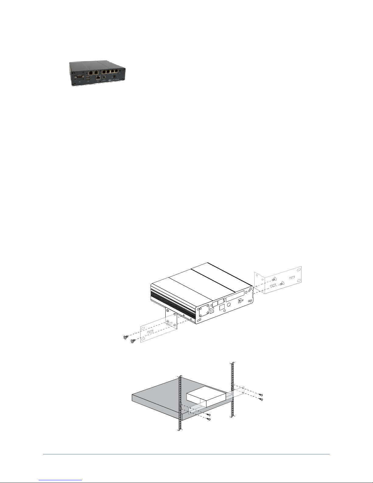
Installing the Uplogix 430 appliance
This section includes:
Unpacking and physical installation
Installing a modem or RS-232 module
Making the connections required for initial configuration
Making the remaining connections
Unpacking the shipping box
Verify that you have received the following items:
Uplogix 430 appliance
Power supply and cord
3-pin mini-DIN to DB-9 console cable
Mounting brackets and fasteners
Installation sheet
Hardware installation
Installing the chassis
The appliance is designed to be mounted in a rack or on the wall, or placed on a tabletop.
To mount the appliance in a rack:
Attach the mounting brackets. They are interchangeable.
Mount the appliance in the rack.
Installation Guide for Uplogix Secure Remote Management Appliances 13
Page 18
Hardware installation
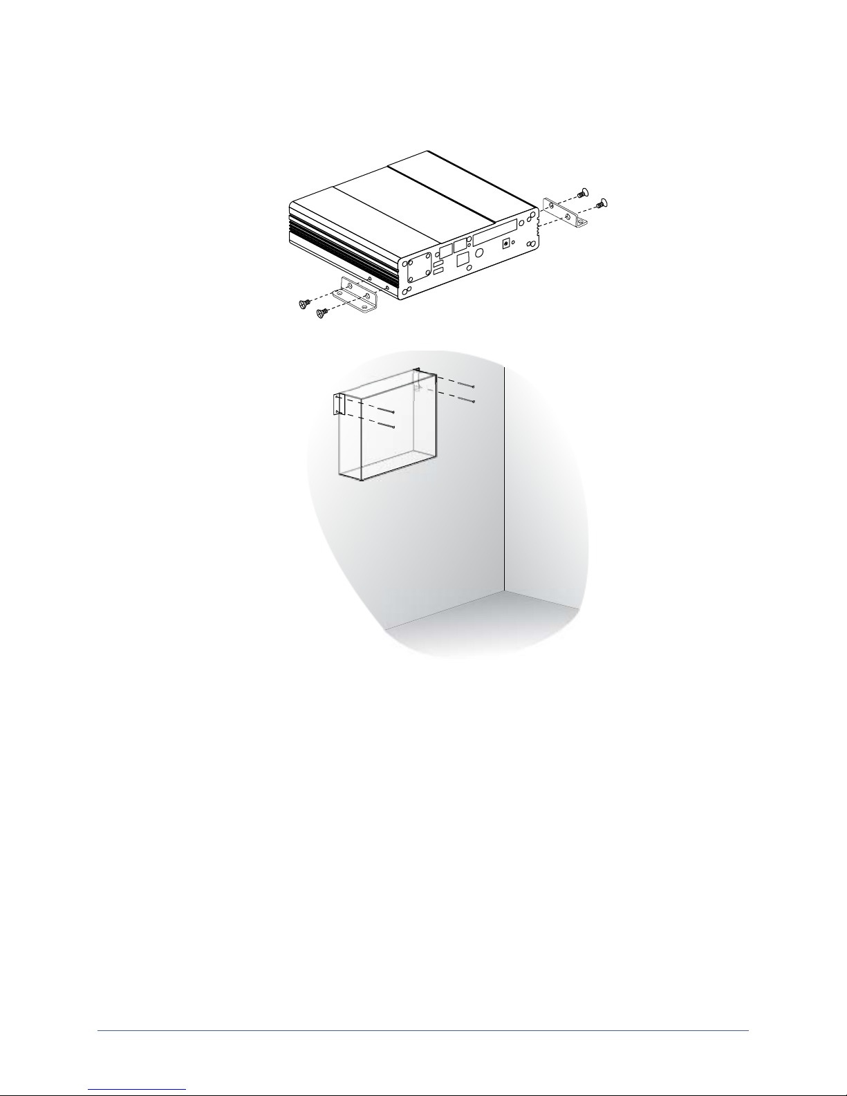
To mount the appliance on a wall:
Attach the mounting brackets.
Mount the appliance on the wall using suitable fasteners.
14 Installation Guide for Uplogix Secure Remote Management Appliances
Page 19
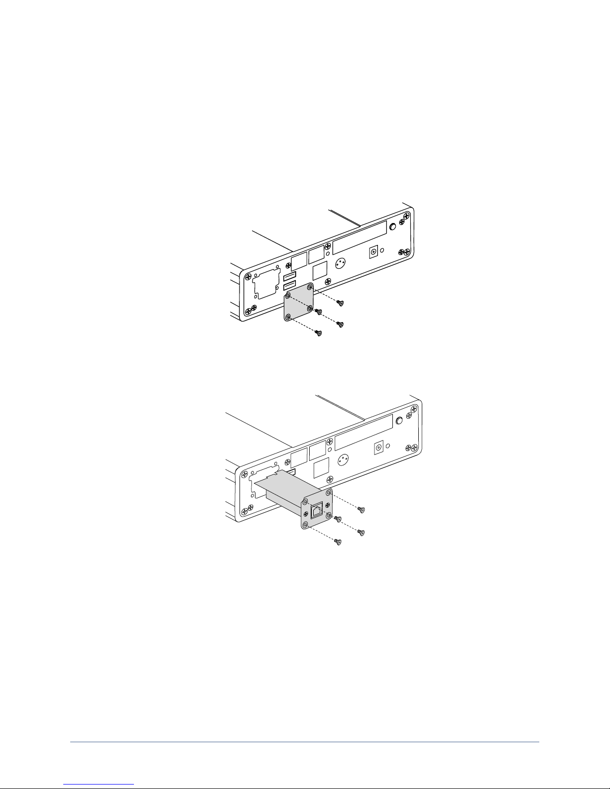
Installing the modem or RS-232 module
If you purchased a V.92 modem or an RS-232 module for the Uplogix 430 appliance, install it
now.
To install the module:
1. If you have already connected the power supply, power off and disconnect it from the
appliance. To power off, press and hold the power/reset switch until the system health
light begins blinking slowly; then release the switch. When the system health light remains
off, you can disconnect the power cable without disruption.
2. Remove the screws securing the blank plate to the appliance.
Hardware installation
3. Gently slide the modem module into place, pressing until you feel the card edge seat in
the connector.
4. Reinstall the screws to secure the modem module.
5. If you disconnected the power supply, reconnect it.
Installation Guide for Uplogix Secure Remote Management Appliances 15
Page 20
Hardware installation
Making the connections required for initial configuration
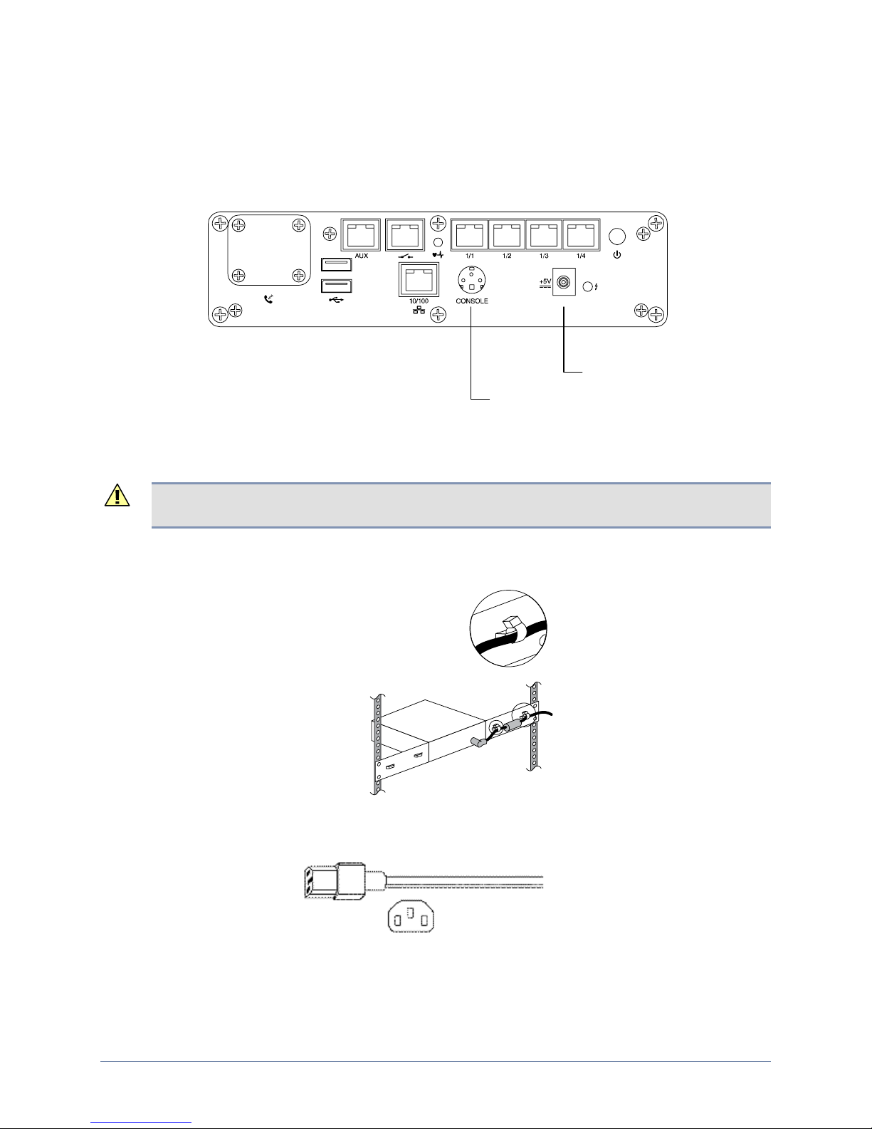
To complete initial setup, you must make these connections:
Power
Console
CONSOLE
Connect to workstation
Connecting power
The Uplogix 430 appliance uses an external power supply, which is shipped with the appliance.
+5V
Connect to power supply
Caution: Use only the power supply shipped with the appliance. Using a different power
supply will void your warranty and may damage the equipment.
Connect the power supply to the DC connector on the appliance.
Secure the cable to the mounting bracket or the rack with a cable tie.
Connect the power cord to the power supply. Use either the provided power cord or one that is
suitable for your location. The power supply uses a power cord with a standard IEC-320-C13
female cord end.
Connect the power cord to a power outlet.
16 Installation Guide for Uplogix Secure Remote Management Appliances
Page 21
Connecting a workstation
To complete initial setup, you must use the console cable to connect your workstation's serial
port to the appliance's console connector.
Following initial setup, you may choose to disconnect the console cable and manage the
appliance via Ethernet.
Making the remaining connections
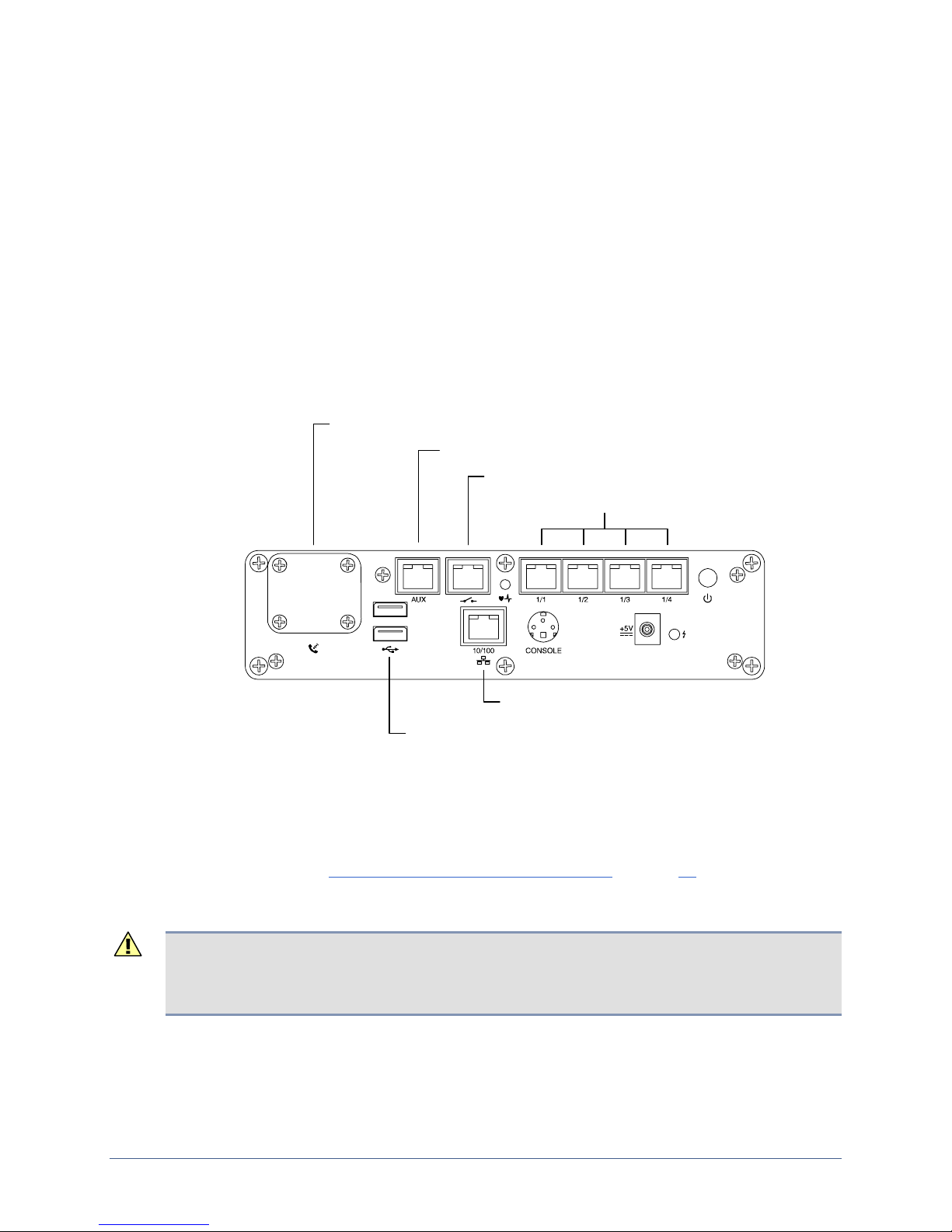
These connections are not required to complete the initial setup:
Devices to be managed
Power controller
Modem
Management Ethernet
Optional hardware authenticator
Install and connect modem module (if purchased)
Hardware installation
Connect secondary Ethernet
Connect power controller
Connect managed devices
Connect management Ethernet
Connect optional hardware authenticator
Connecting a power controller
Connect the power controller's serial port to the power control port on the appliance.
Connecting the modem
If you purchased a V.92 modem module or an RS-232 module for the Uplogix 430 appliance,
install it now. Refer to
If a V.92 modem module is installed, connect it to a standard analog (POTS) phone line
provided by your local telephone company.
Caution: To prevent equipment damage, do not connect the internal modem to digital PBX
systems, VoIP analog terminal adapters, or cellular modems. It is designed for use with analog
telephone lines only. Uplogix is not responsible for damage caused from attaching the modem
to a digital phone switch.
If an RS-232 module is installed, connect it to an external modem for out-of-band dial-up
connectivity.
Installing the modem or RS-232 module on page 15.
Installation Guide for Uplogix Secure Remote Management Appliances 17
Page 22

Hardware installation
Connecting management Ethernet
To manage the appliance and attached devices in-band through the network, connect the
management Ethernet port on the front panel to your Ethernet network. Speed and duplexing
default to autonegotiation.
If you have purchased this capability, you may wish to make a secondary management
Ethernet connection through the AUX port, to the left of the power controller connector. The
main and secondary management Ethernet connections must be on the same subnet, but can
be through separate switches for redundancy.
Connecting devices to be managed
Connect the console ports of up to four network devices to the four serial ports (1/1 through
1/4) on the appliance.
Connecting a hardware authenticator
For automatic one-time password authentication during out-of-band operation, connect an
RSA® SecurID® SID800 hardware authenticator to one of the USB ports.
18 Installation Guide for Uplogix Secure Remote Management Appliances
Page 23
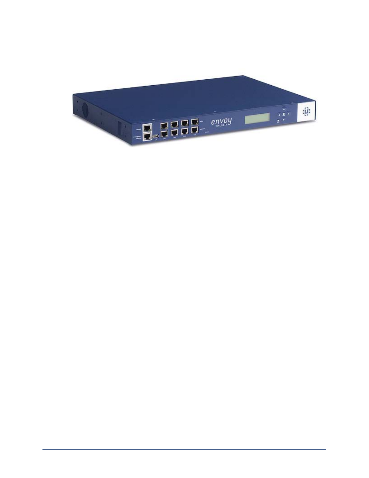
Installing the older 4-port Uplogix appliance
This procedure includes:
Unpacking and physical installation
Making the required connections
Installing optional expansion modules
Hardware installation
Unpacking the shipping box
Verify that you have received the following items:
Uplogix secure remote management appliance
Cable kit:
à 6 Cat 5e cables, white
à RJ-45 to DB-9 adapters, gray (one is standard pin-out, one is custom)
à RJ-45 Ethernet crossover adapters, red (2)
à Phone cable, silver
Power cord
Power cord retainer
Rack mounting brackets (2)
Wall mounting brackets (2)
Package of bracket attachment screws
Vinyl feet
Installation Guide for Uplogix Secure Remote Management Appliances 19
Page 24
Hardware installation
Installing the chassis
You can install the Uplogix appliance on the desktop, in a rack, or mounted on a wall.
On the desktop
Install the vinyl feet on the bottom of the appliance, then place the appliance so that:
It is away from heat sources
The chassis cooling vents are not blocked
The front and back of the appliance are easily accessible
It rests directly on a stable surface and is not stacked on other equipment
No other objects will be placed on it
Caution: Do not stack the chassis on any other equipment, and do not place other objects on
top of it. The chassis cover is not designed to support weight.
In a rack
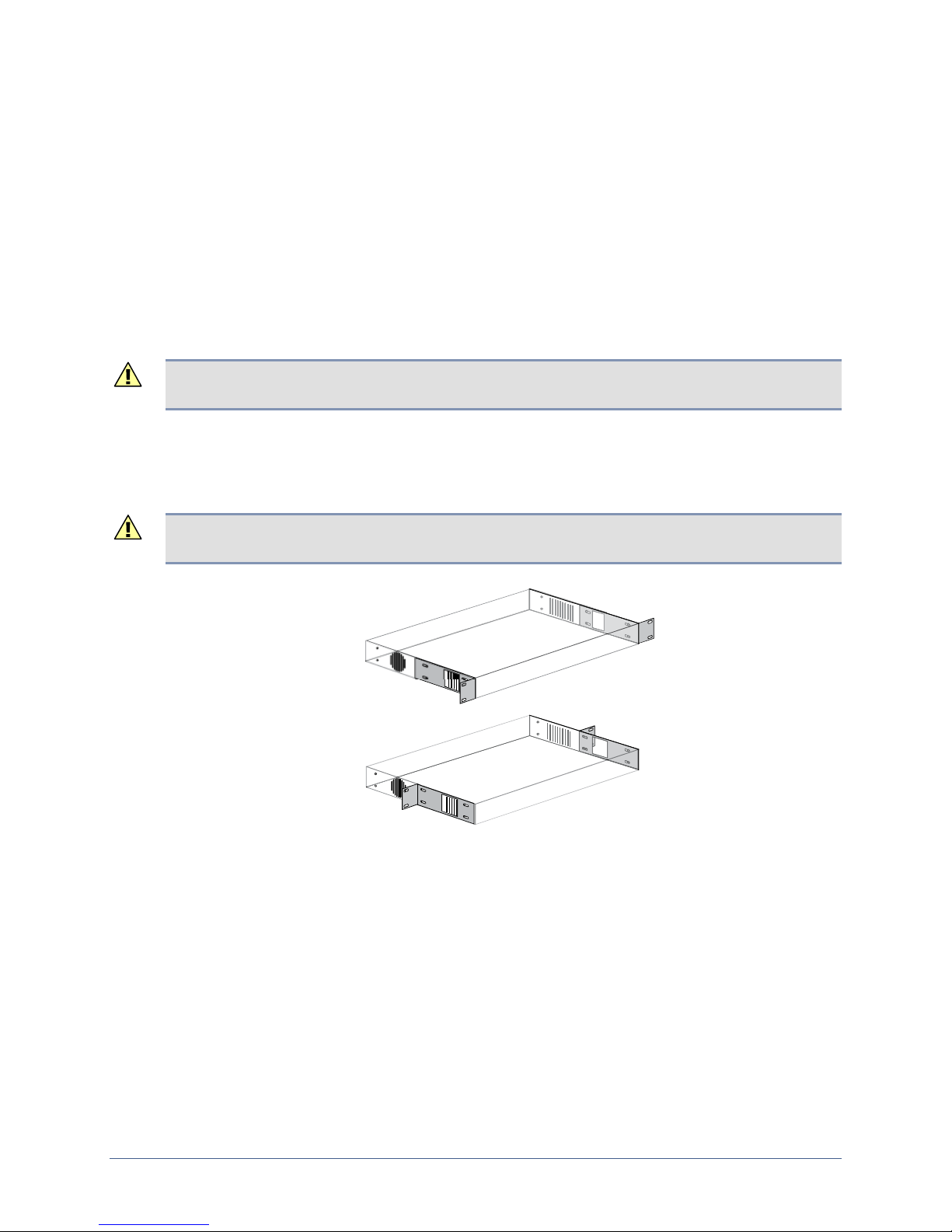
Attach the rack-mounting brackets as shown. Note that one bracket’s ventilation opening is
near the center, and the other bracket’s ventilation opening is near one end. Be sure the
openings in the mounting brackets line up with the ventilation slots in the chassis.
Caution: Ensure that the openings in the mounting brackets line up with the ventilation
openings in the chassis. If the air flow to the chassis is blocked, the appliance will overheat.
Front mount
Mid mount
Secure the appliance to the rack.
20 Installation Guide for Uplogix Secure Remote Management Appliances
Page 25
Hardware installation
On the wall
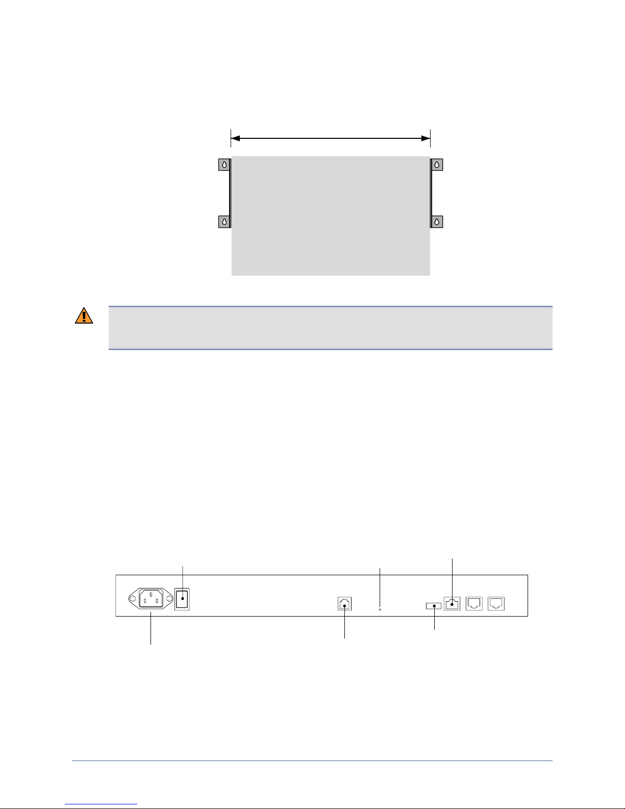
To mount the Uplogix appliance on a wall, install the wall-mounting brackets on the wall as
shown.
17 in. (43.2 cm)
Attach the appliance to the brackets, with its LCD readout facing up.
Warning: This model of Uplogix appliance contains a lead-acid battery that must not be
mounted upside down. To prevent damage, mount the appliance with the LCD readout facing
up. Uplogix is not responsible for damage caused by mounting the chassis incorrectly.
Making connections
Connections include:
Power
Modem
Power controller
Management Ethernet and console
Optional hardware authenticator
Optional expansion modules
Devices to be managed
This model includes a built-in temperature and humidity sensor. For this model, no external
sensor is needed.
Power switch
Power
Modem
power
indicator
Power control
USB port
for expansion
modules
Installation Guide for Uplogix Secure Remote Management Appliances 21
Page 26
Hardware installation
Connecting power
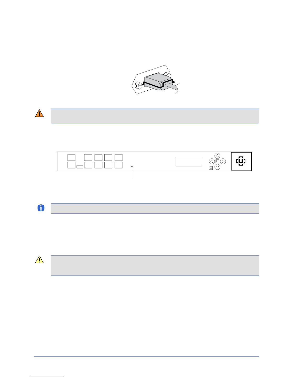
Connect the power cord to the power receptacle at the left rear of the appliance. If the
installation is subject to vibration, you may wish to attach the power cord retainer to the posts
on the power receptacle to hold the cord in place.
Connect the power cord to an AC power source, then power on the appliance.
Warning: The plug-socket combination serves as the main disconnecting device and must be
accessible at all times.
Verify that the LCD displays progress messages and the battery indicator lights green to show
that the appliance is operating on external AC power.
battery indicator
At the end of the power-on sequence, the appliance displays the message
Uplogix status
good.
Note: When the appliance operates on battery power, the battery LED lights red.
Typical boot time is two or three minutes. When the Uplogix appliance has completed its boot
process, the front panel displays status information.
Connecting the modem
Connect the modem port to a standard analog (POTS) phone line provided by your local
telephone company for out-of-band dial-up support.
Caution: Do not connect the on-board modem to digital PBX systems, VoIP analog terminal
adapters, or cellular modems. It is designed for use with analog telephone lines only. Uplogix
is not responsible for damage caused from attaching the modem to a digital phone switch.
Connecting a power controller
Connect a power controller to the power controller port on the back of the appliance.
The appliance can control a variety of managed power controllers. The power controller, used
to monitor and control power to the various network devices, completes visibility and low-level
control of the network device.
Each power controller has its own cabling requirements. Refer to the
Uplogix Secure Remote Management Appliances
for wiring instructions for each of the
supported controllers.
Reference Guide for
22 Installation Guide for Uplogix Secure Remote Management Appliances
Page 27
Hardware installation
Connecting management Ethernet and console
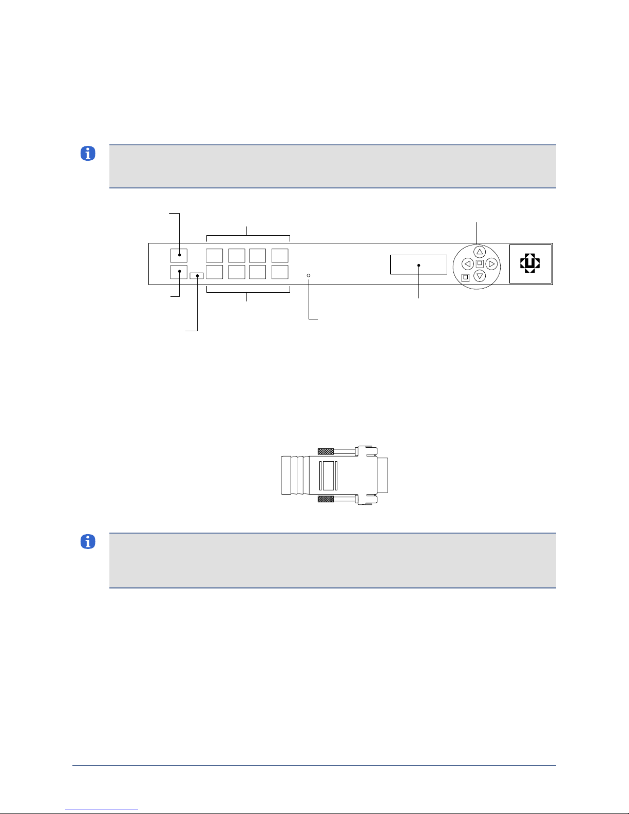
To manage the Uplogix appliance and attached devices in-band through the network, connect
one of the white Cat 5e cables included with the appliance to the management Ethernet port
on the front panel and to your Ethernet network. The speed negotiation is auto-detected by
default.
Note: One of the LEDs on the RJ-45 Ethernet port will glow when link integrity pulse is
detected, indicating that low-level connectivity has been established. If after connecting this
port, neither indicator lights, try combining the crossover dongle to one side of the connection.
Management
console
Management
Ethernet
USB port
for expansion
modules
Port 1/1 through 1/4
serial
Port 1/1 through 1/4
Ethernet
Keypad
Display
battery indicator
You may wish to make a secondary management Ethernet connection through the Aux 1 port
on the back of the appliance. The main and secondary management Ethernet connections
must be on the same subnet, but can be through separate switches for redundancy.
To manage the Uplogix appliance and attached devices using the TTY console, connect the RJ45 to DB-9 adapter to your computer’s serial port, and connect the RJ-45 cable from the
appliance's
console port to the adapter.
The default settings for the console port are 9600, 8, N, 1.
Note: Link status is indicated by one of the LEDs on the RJ-45 serial port. If neither light
glows after connecting a device using one of the supplied white Cat 5e cables, the port should
be changed to use DTE. The rolled console cables (often flat) provided with network devices
usually require this change as well.
Adding USB connectivity
If your installation will use two expansion modules and hardware authentication, you will need
to connect a USB hub for additional USB connectivity. Using a bus-powered hub reduces
reliance on external power sources.
Optional: Connecting a hardware authenticator
For automatic one-time password authentication during out-of-band operation, connect an
RSA® SecurID® SID800 hardware authenticator to one of the appliance’s USB ports. Note
that in this case you will need to use a USB hub if you wish to connect more than one
expansion module..
Installation Guide for Uplogix Secure Remote Management Appliances 23
Page 28
Hardware installation
Connecting managed devices
If you will use expansion modules with the Uplogix appliance, install them now (see next
section).
Without the optional expansion modules, the Uplogix appliance can monitor and manage up to
four separate network devices such as switches and routers.
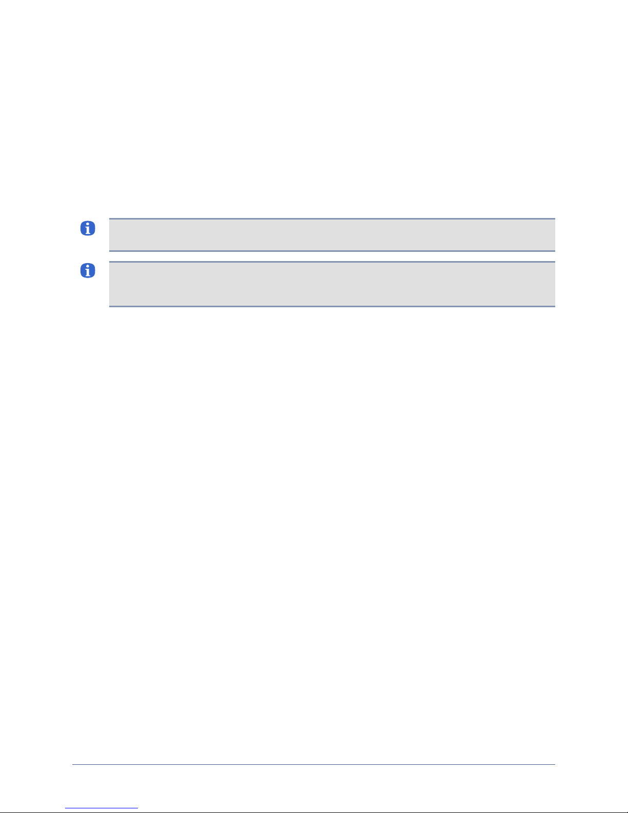
Use the four serial ports on the front panel of the appliance to connect to the console ports of
up to four separate network devices.
To provide for dedicated TCP/IP connectivity to these devices, and additional diagnostic
features of the appliance, use the corresponding four Ethernet ports located on the front panel
and connect to an available Ethernet port on each of the devices that you want to monitor.
Note: The white Cat 5e cables included with the Uplogix appliance can be used with both
serial and Ethernet ports.
Note: The Uplogix appliance's Ethernet transceivers are configured for MDI, so it should not
require a crossover to connect this port to a switch, but when connecting to other end-point
devices such as routers and firewalls, the included crossover dongle may be necessary.
The User's Guide for Uplogix Secure Remote Management Appliances includes
information on configuring the appliance's device ports to work with the connected devices.
24 Installation Guide for Uplogix Secure Remote Management Appliances
Page 29
Installing optional expansion modules
The optional expansion modules provide an additional eight ports each. The Uplogix appliance
can accommodate two expansion modules, for a total of 20 device ports for each Uplogix
appliance.
Unpacking the shipping box
Verify that you have received these items:
Expansion module
Cable kit containi ng:
à 8 Cat 5e cables (white)
à 1 RJ-45 to DB-9 Adapter (gray)
à 1 USB Type A to Type B cable
Rack-mount shelf
Package of bracket attachment screws (8)
Blank plate
The expansion ports differ from the on-board device ports in the following ways:
Fixed Crossover – The expansion ports are designed to be DCE and connect to most
network devices using a standard Cat 5e cable. The software-selectable null modem (DTE)
is not available.
Link and Activity indicators – The green console link status and yellow activity indicators
are not present on expansion modules.
Hardware installation
Installing the expansion modules
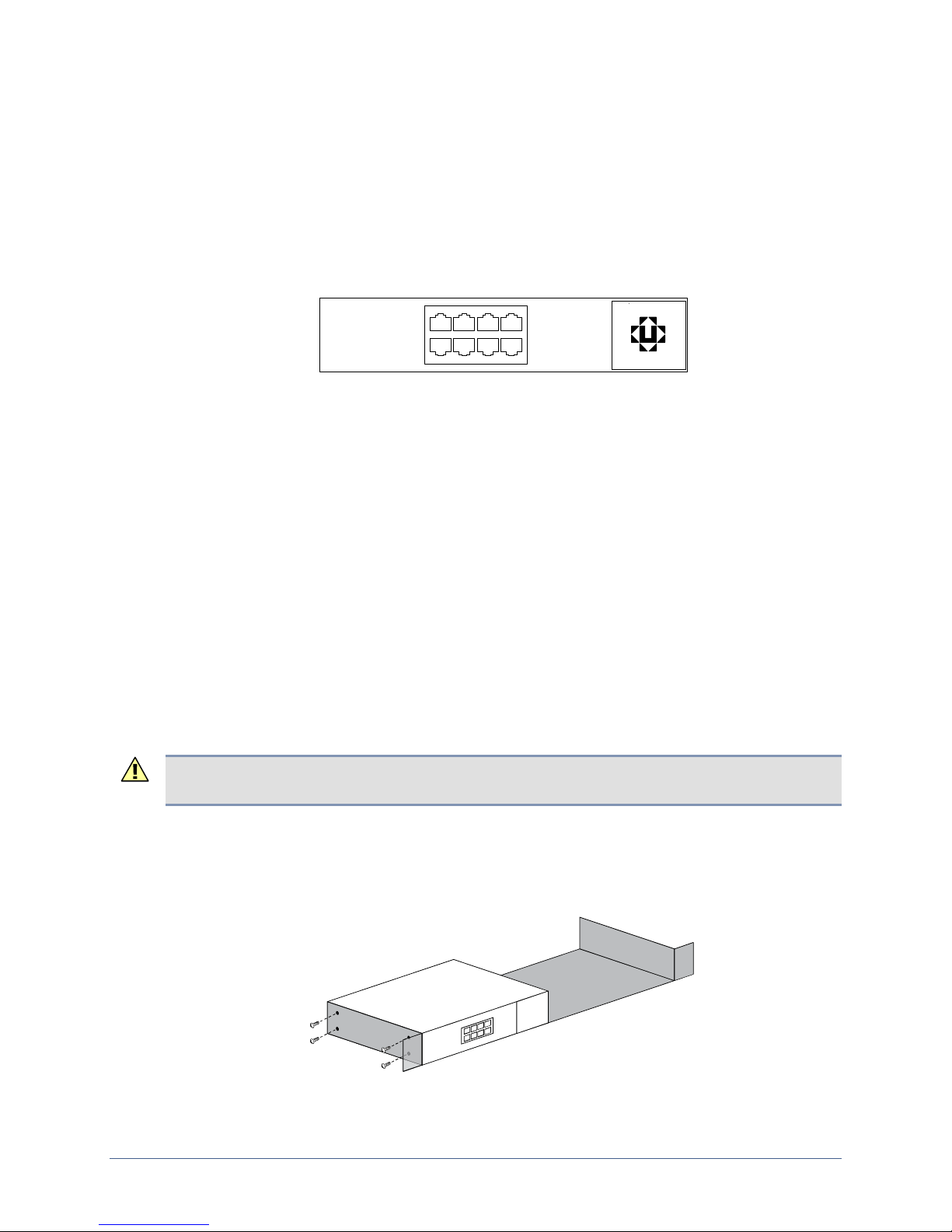
The expansion module can be installed in a 19-inch rack or placed on a flat surface and used
as a desktop device.
Caution: Do not place other objects on top of the expansion module. The chassis cover is not
designed to support weight.
The included rack-mounting shelf is designed to mount one or two expansion modules.
To install the expansion module in a standard 19-inch rack, attach it to the included rack-
mounting shelf. The expansion module is designed to mount on either side of the shelf. A
blank plate is included to cover the open space if only one expansion unit is installed.
Installation Guide for Uplogix Secure Remote Management Appliances 25
Page 30

Hardware installation
Connecting the expansion modules
To connect expansion modules to the Uplogix appliance:
Use the supplied USB cables to connect the expansion modules to the two USB ports on the
Uplogix appliance. One is located on the back, near the power controller port, and one is on
the front near the Management Ethernet connection.
The power LED on the rear of the expansion module indicates communication with the Uplogix
appliance.
The first expansion module that you connect during a new installation will be designated slot 2;
the second is slot 3.
You can use the
expansion modules, their serial numbers, and the ports associated with each. The
dashboard
Note: If you are using two expansion modules and hardware authentication, you will need a
USB hub for additional connectivity.
show version command to display information including the number of
command should display information for all available ports.
show
26 Installation Guide for Uplogix Secure Remote Management Appliances
Page 31

Replacing an expansion module
The appliance associates the expansion module’s serial number to the slot designation, so you
will need to clear the slot data when you replace the expansion module. This does not affect
the port data.
To replace an expansion module:
1. Disconnect the expansion module from the appliance. This generates an alarm.
2. Dismount the expansion module from the mounting shelf if necessary.
3. Use the config system clear slot command to clear the information about the
expansion module from the database.
4. Install the replacement module in the desired location – for example, on the mounting
shelf.
5. Connect the replacement module to the appliance using the USB cable.
6. Use the restart command to restart the appliance.
7. Complete the connections to managed devices.
In this procedure, the Uplogix appliance retains the module's port configurations in the port
database.
Removing an expansion module that will not be replaced
Hardware installation
Use this procedure to take an expansion module out of service without replacing it.
To remove an expansion module permanently:
1. Disconnect the expansion module from the appliance. This generates an alarm.
2. Dismount the expansion module from the mounting shelf if necessary.
3. Use the config system clear slot command to clear the stored information about the
module. This clears the alarm as well.
4. After you clear the slot, use the config system clear port command to ensure that the
port data is completely cleared from the database.
Installation Guide for Uplogix Secure Remote Management Appliances 27
Page 32

Hardware installation
28 Installation Guide for Uplogix Secure Remote Management Appliances
Page 33
Quick setup
You can configure the appliance as a single network management tool, or you can configure it
to be managed by an Uplogix Control Center element management system (EMS).
Uplogix appliances can be initially provisioned via console connection. The Uplogix 32-port
appliance and the older 4-port appliance can also be provisioned via the front panel keypad.
Note: Substitute appropriate IP addresses and other values for your deployment for those
shown in the examples.
In this chapter:
Initial configuration using the keypad
Initial configuration via console connection
Remote access via the management IP connection
Changing the administrator's password
Setting up a unit to be managed by a server
Initial configuration using the keypad
This method is not available for the Uplogix 430 appliance. To set up an Uplogix 430 appliance,
go to the next section,
The Uplogix appliance is ready to provision when the front panel display begins to scroll
information.
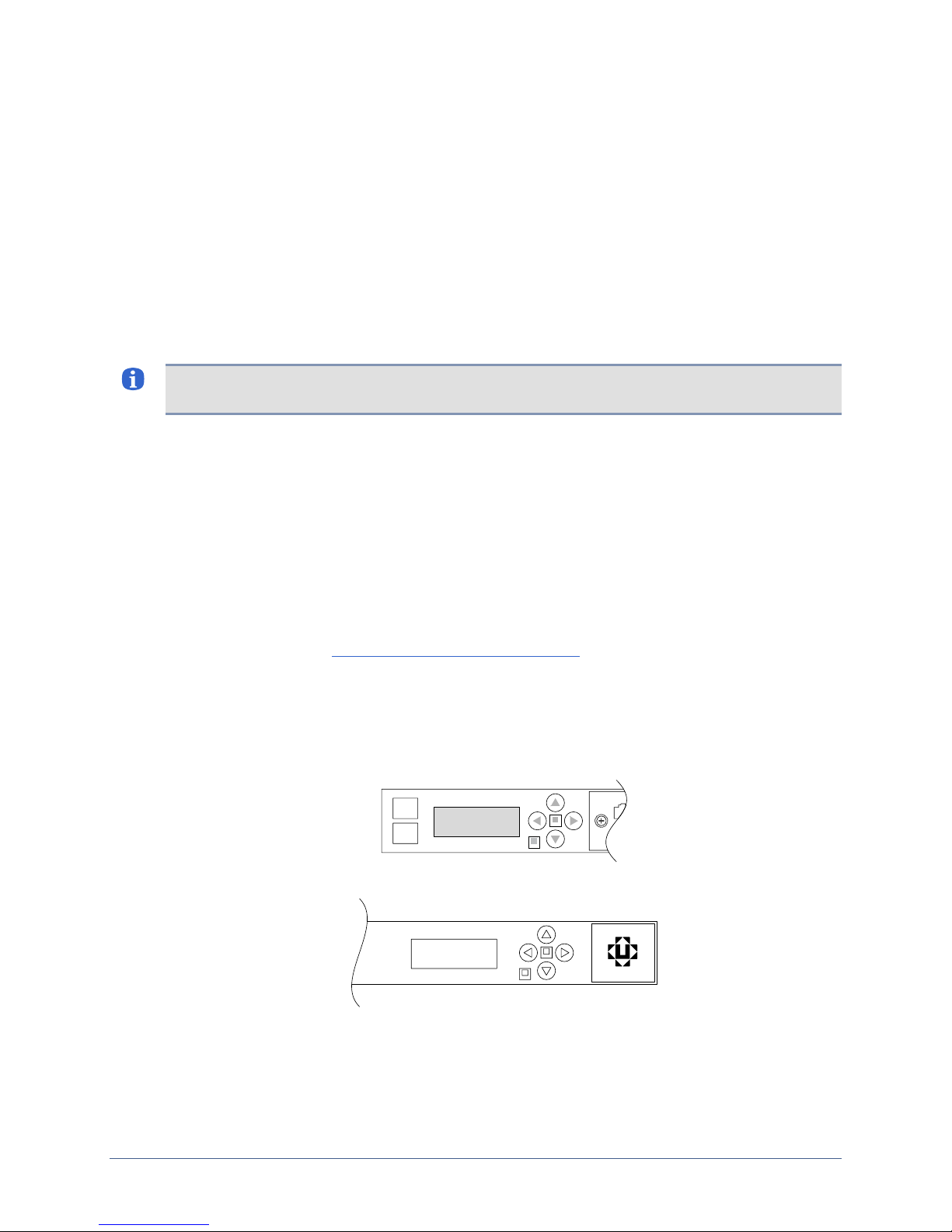
The keypad located on the front panel provides up, down, left, and right keys (labeled with
arrows) as well as enter and back keys. The left and right arrows move the cursor left and
right, respectively. The up and down keys change numerical values.
When you use the keypad, no username/password is required.
For each setting, you can accept the default or existing setting by pressing the Enter key.
Initial setup via console connection.
Installation Guide for Uplogix Secure Remote Management Appliances 29
Page 34

Quick setup
1. Press the Enter key on the keypad to access the menu. The > character appears to the left
2.
3.
4. Configure the appliance’s subnet mask in the same manner:
of the currently selected option. Press Enter or the right arrow button to access the
configuration screens.
>Configure
Restart
The Uplogix appliance can use a DHCP server for network addressing. Brackets appear
around the selected option. Use the left and right arrows to select your response and press
enter to advance. If you are using DHCP, press the enter key and skip to Step 6. You can
review the assigned IP address after configuration is complete by re-entering the
configuration dialog.
Use DHCP?
[Yes] No
If you choose not to use DHCP, enter the IP address that the appliance should use. Use
the left and right arrows to move between digits of the IP address, and the up and down
arrows to change individual digits. The > prompt points to the digit to be changed.
IP Address:
>000.000.000.000
When entering an IP address, built-in validation keeps the octet below 255 at all times.
You may need to change the second digit before you can change the first digit. For
example, to change the number 180 to 240, you must change the second digit from 8 to 4
before you can change the first digit from 1 to 2. The validation will not allow an address
280, so the first character will toggle between 1 and 0 until you change the second
character to keep the octet at or below 255.
Netmask:
>255.255.255.000
5.
Specify a default route for network connectivity.
Default Route:
>000.000.000.000
6.
Whether you use DHCP or a static IP address, the appliance next prompts you to select
speed and duplexing options.
Autonegotiation
[Yes] No
This setting needs to match your network. If there is an autonegotiation mismatch, the
appliance defaults to 10/half.
7. If you choose not to use autonegotiation, select speed and duplexing to match your
network.
[100full] 10full
100half 10half
8. Enter an IP address for the Uplogix Control Center element management system (EMS)
only if this unit is to be managed by an Uplogix Control Center. Otherwise, do not enter an
IP address at this prompt. Press Enter to skip to the next configuration item.
EMS Server IP:
>127.000.000.001
If the appliance has already been associated with an Uplogix Control Center that uses a
DNS name, this prompt is not displayed.
9. If a pulse server is to be used, enter the IP address here. Consult the User’s Guide for
Uplogix Secure Remote Management Appliances for more information about Pulse
functionality.
Pulse Server IP:
127.000.000.001
30 Installation Guide for Uplogix Secure Remote Management Appliances
Page 35
Quick setup
10. If you connect to the console port via a null-modem cable, enable the null modem setting
on the Uplogix appliance. Otherwise, select No. If the console connection does not work,
try changing this setting.
Use null modem?
Yes [No]
11. The appliance is now configured. Select “Yes” to save your changes.
Confirm Changes?
Yes [No]
If you have configured the appliance with a management IP address, you can now manage it
remotely via an SSH session. See
Remote access via the management IP connection on page
34.
Note: For security, you may disable the keypad after you finish the initial setup. See Locking
the keypad and changing the admin password on page 34.
Installation Guide for Uplogix Secure Remote Management Appliances 31
Page 36
Quick setup
Initial configuration via console connection
To configure the Uplogix appliance via the console port, connect directly to the console port on
the front of the appliance. This port may be labeled
options available via the keypad are also available through the command line. These are
described below.
Open a connection to the appliance using a terminal client on your computer. Supported
terminal clients include:
Windows HyperTerminal
ZTerm (Macintosh OS X)
Minicom (Unix/Linux)
The default console connection settings are 9600 baud, 8 data bits, 1 stop bit, no parity. For
best results, set your terminal emulator to use ANSI encoding.
Note: The Uplogix 430 does not use flow control. If you use HyperTerminal, you must disable
flow control when configuring the session.
After you connect to the appliance, you will be prompted for a username and password. The
default username is
are case-sensitive.
admin and the default password is password. Usernames and passwords
console or 10101. The configuration
Note: Some settings shown in the examples may be unavailable on your appliance.
32 Installation Guide for Uplogix Secure Remote Management Appliances
Page 37

Configuring the appliance for your LAN
To configure the appliance’s network addressing, use the config system ip command. The
appliance displays the current settings, and presents a prompt asking whether you want to
make changes.
[admin@A101100303]# config system ip
--- Existing Values ---
Use DHCP: Yes
Management IP: 172.30.151.8
Host Name: A101100303
Subnet Mask: 255.255.255.0
Broadcast Address: 172.30.151.255
Default Route: 172.30.151.254
Speed/duplex: auto:100full
DNS Server:
MAC Address: 00:0F:2C:00:02:BF
Change these? (y/n) [n]:
--- Enter New Values ---
Use DHCP: (y/n) [y]: n
Management IP: [172.30.151.8]: 172.30.151.109
Host Name: [A101100303]: xyzcoAus01
Subnet Mask: [255.255.255.0]:
Default Route: [172.30.151.254]:
speed/duplex: [auto:100full]:
DNS Server IP: []:
Warning: Remote connections may be lost if you commit changes.
Do you want to commit these changes? (y/n):
y
Quick setup
y
The changes take effect after you commit them.
If you have configured the appliance with a management IP address, you can now manage it
remotely via an SSH session.
Note: DNS names are only required for Service Level Verification tests. All other commands
are DNS-independent.
Configuring an optional pulse server
Specify a pulse server using the config system pulse command.
[admin@xyzcoAus01]# config system pulse
--- Existing Values ---
Use Pulse: false
Pulse Server IP: 127.0.0.1
Pulse Server Port: 7
Dial Out when pulse fails: no
Change these? (y/n) [n]:
--- Enter New Values ---
Enable ppp to dial out on pulse failure: (y/n) [n]: n
Use Pulse: (y/n) [n]: y
Pulse IP: [127.0.0.1]: 192.168.1.2
Pulse Port: [7]:
Do you want to commit these changes? (y/n):
The above example enables Pulse but does not enable the dial-out PPP function. The Uplogix
appliance can use rules to generate alarms even when Pulse fails. For more information on
Pulse and alarms, consult the
Appliances
.
y
User’s Guide for Uplogix Secure Remote Management
y
Installation Guide for Uplogix Secure Remote Management Appliances 33
Page 38

Quick setup
Remote access via the management IP connection
Uplogix appliances use Secure Shell (SSH) v2 software to provide secure remote access. Your
remote client application must also support SSH v2.
Supported clients include:
PuTTY
SSH® Tectia™
VanDyke® SecureCRT®
SSHTerm for Windows
iTerm for Macintosh OS X
UNIX’s built-in ssh command
For example, in a UNIX command line, type:
Log in with the default username and password (admin and password). When you are logged
in, you will see a prompt similar to the following:
[admin@A101100303]#
Note: The first time your SSH client connects to an SSH host following installation or upgrade,
you may see an SSH key fingerprint message. This is normal. The client usually caches the
key for subsequent use and warns if the host has changed, often indicating network
eavesdropping.
Locking the keypad and changing the admin password
To ensure security, you may wish to lock the keypad and/or change the admin user’s
password when you log in for the first time.
To lock the keypad, use the
restart, and factory reset functions will still be available from the keypad but the configuration
menu will not be available.
admin user cannot be deleted and has access to all commands.
The
To change the
[admin@xyzcoAus01]# config password
New Password: ********
Confirm Password: ********
Password changed.
You have completed the basic setup.
If the appliance is to be used with an Uplogix Control Center element management system,
continue to
Refer to the
detailed information about configuring and managing the appliance.
admin account’s password, use the config password command.
Setting up the appliance to be managed by an Uplogix Control Center.(next page).
User’s Guide for Uplogix Secure Remote Management Appliances for
config system keypad disable command. The shutdown,
34 Installation Guide for Uplogix Secure Remote Management Appliances
Page 39

Quick setup
Setting up an appliance to be managed by an Uplogix Control Center
After you have completed the initial configuration, you can place the appliance under
management by an Uplogix Control Center element management system. You can create a
placeholder for the appliance on the server beforehand.
If there is a placeholder on the Uplogix Control Center when the Uplogix appliance contacts it,
the Uplogix Control Center automatically places the appliance in the appropriate group and
loads the appropriate configuration.
If there is no placeholder on the Uplogix Control Center, the appliance is accessible but most
management functions are unavailable until it is explicitly assigned to a group of appliances
via the Uplogix web interface.
Note: Uplogix appliances must use the same version of software as the Uplogix Control Center
element management system (EMS) that manages them, though they do not need to use the
same patch release.
Examples:
An EMS running version 3.4 software cannot manage Uplogix appliances that have been
upgraded to version 3.5 software; nor can an Uplogix Control Center running version 3.5
software manage Uplogix appliances that are still using version 3.4 software.
An Uplogix Control Center EMS running any version 3.5.x software can manage Uplogix
appliances running any 3.5.x software.
Installation Guide for Uplogix Secure Remote Management Appliances 35
Page 40
Quick setup
Creating a placeholder on the Uplogix Control Center (optional)
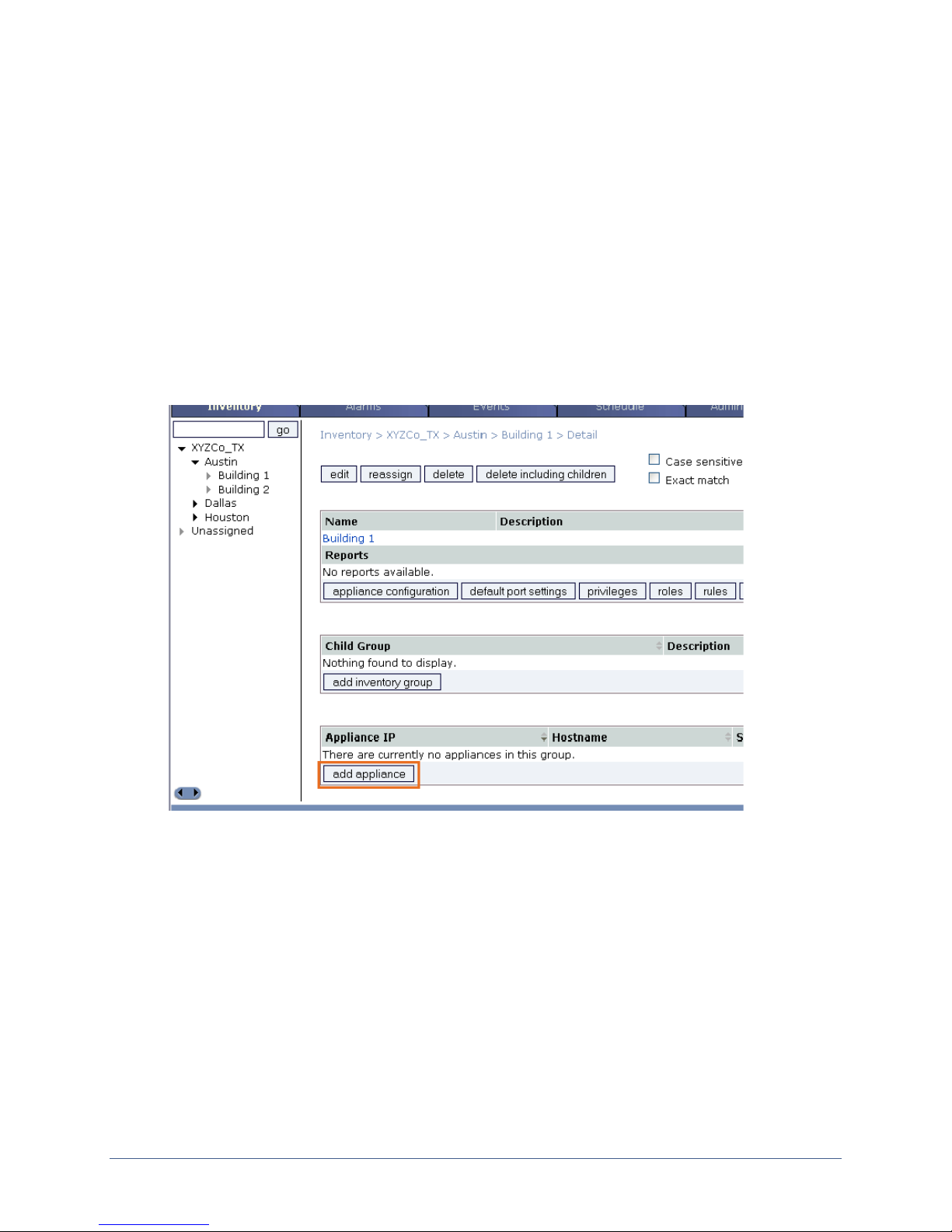
Inventory > group
Creating a placeholder in advance allows you to add the Uplogix appliance directly to the
inventory group of your choice, so that users with the appropriate privileges within that group
can manage the appliance as soon as it contacts the Uplogix Control Center. The appliance will
also inherit the configuration settings, privileges, roles, rules, preferences, and other defaults
from that inventory group.
You can do this step before the Uplogix appliance is physically installed.
You will need the serial number of the appliance you wish to add. This number can be found
by issuing the
plate on the bottom of the appliance.
Select a group from the inventory list to bring up the Group Detail page, and click
appliance to open the Create Uplogix dialog box.
show version command from the appliance's command line or referencing the
add
36 Installation Guide for Uplogix Secure Remote Management Appliances
Page 41
Quick setup
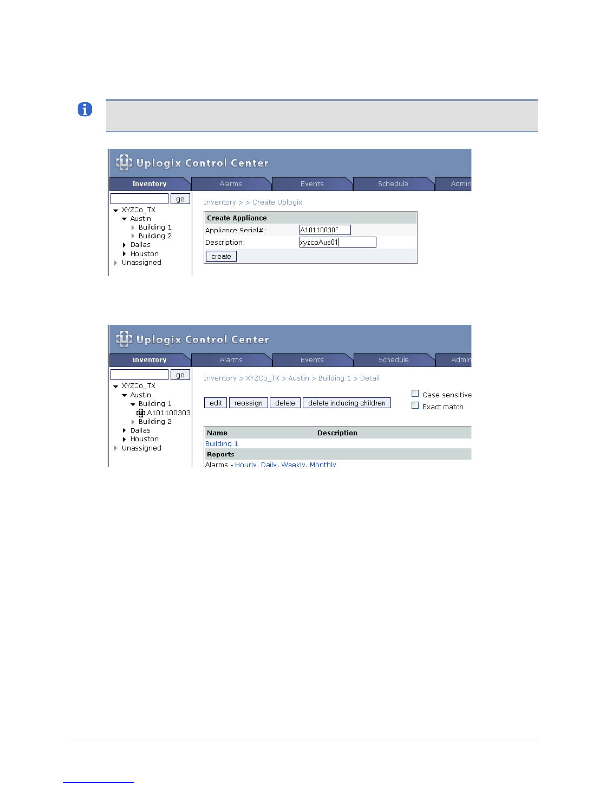
In the Create Appliance dialog box, enter the serial number of the Uplogix appliance and an
optional description. Click
create to add the appliance.
Note: When completing text fields, use only printing characters. Spaces are considered
printing characters.
The inventory list automatically refreshes and displays the appliance. Its symbol appears in
black because there is no communication between the server and the appliance at this point.
Installation Guide for Uplogix Secure Remote Management Appliances 37
Page 42
Quick setup
Connecting to the Uplogix Control Center from the Uplogix appliance (required)
From the Uplogix appliance’s command line interface, issue the config system management
command. Use your Uplogix Control Center's IP address in place of the IP address in this
example:
[admin@xyzcoAus01]# config system management
--- Existing Values ---
Use EMS: false
EMS Server Hostname or IP: 127.0.0.1
EMS Server Port: 8443
Heartbeat interval (seconds): 30
Last successful heartbeat: (not yet contacted)
Change these? (y/n) [n]:
--- Enter New Values ---
Use EMS: (y/n) [n]: y
EMS Server Hostname or IP: [127.0.0.1]: 172.30.238.20
EMS Server Port: [8443]:
Set archive location to 172.30.238.20: (y/n) [y]:
Set ntp location to 172.30.238.20: (y/n) [y]:
Heartbeat interval (seconds): [30]:
Do you want to commit these changes? (y/n):
Updating archive to point to 172.30.238.20
Enabling NTP to point to 172.30.238.20
y
y
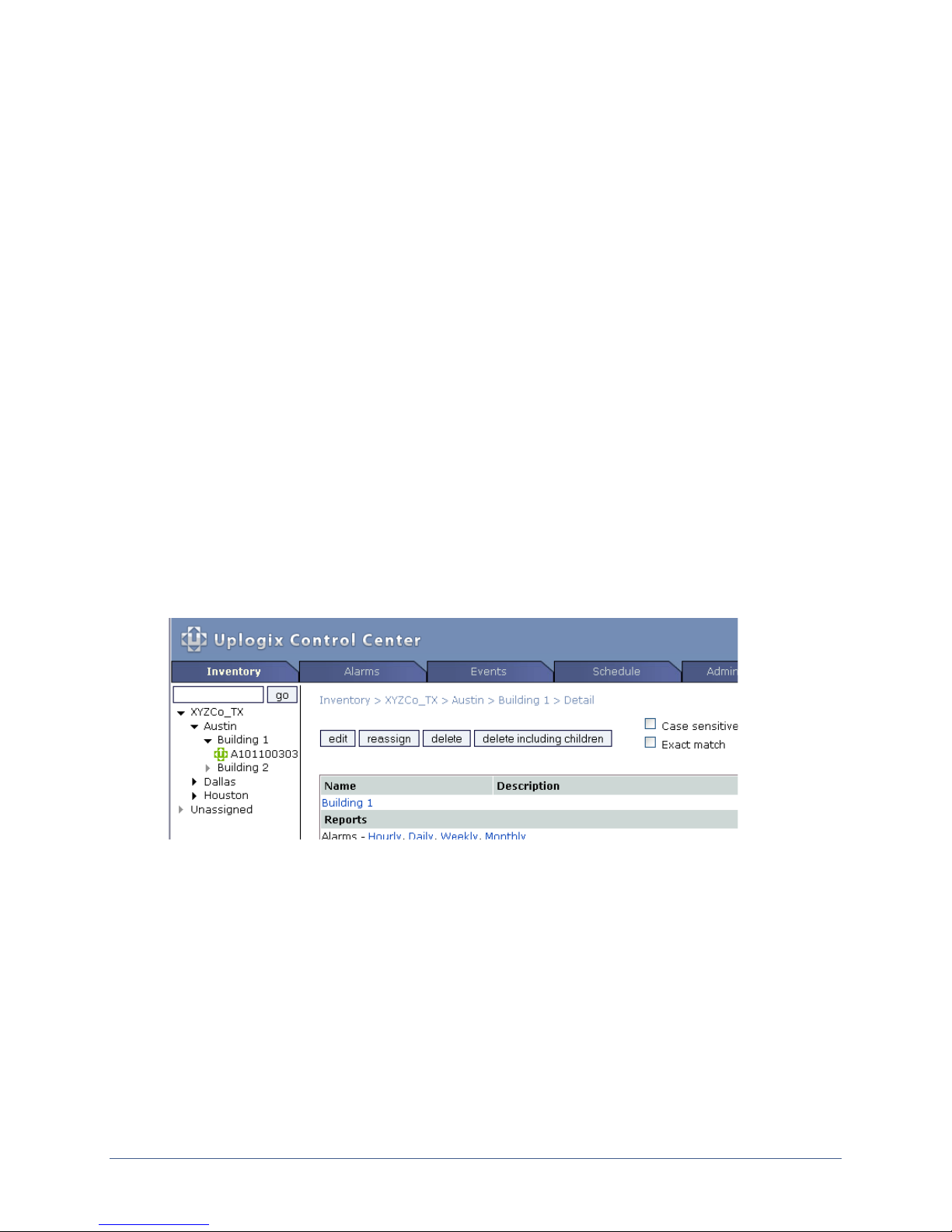
If you set up a placeholder in the inventory before you do this, the black icon for the
placeholder turns green and the serial number is replaced by the appliance's hostname (if one
has been configured on the appliance) when the Uplogix Control Center has received a full
heartbeat. The default heartbeat interval is 30 seconds.
If you did not create a placeholder on the Uplogix Control Center, the appliance will be placed
Unassigned group. You will need to reassign it into another inventory group to manage
in the
it.
Refer to the
User’s Guide for the Uplogix Control Center Element Management System
for detailed information about configuring and managing the Uplogix appliance from the
Uplogix Control Center.
38 Installation Guide for Uplogix Secure Remote Management Appliances
Page 43

Support and regulatory information
Getting technical support
The Uplogix technical support web site allows you to open and review support requests,
browse the knowledge base and download software updates. You must have a user account to
view this site.
Requesting an account
To create an account, send an email to [email protected] with the subject line “create
account”. Include this information:
organization name
account user’s email address
user’s general contact information
You may request up to 10 accounts.
Requesting support
If you need to contact Uplogix customer support, please provide this information:
Product model
Serial number and software version (use the show version command from the command
line or use the arrow keys on the front panel to scroll through the information on the
display)
Phone: 512-857-7070
Fax: 512-857-7002
www.uplogix.com/support
URL:
Providing comments about this guide
Did you find the information you needed?
Was it accurate?
Did it help you?
Please contact our publications staff at
with this guide's accuracy, completeness, or clarity.
We want you to be successful using our products. If you find a problem with this material, we
will do our best to fix it.
Regulatory notices
[email protected] to notify us of any issues
The following section provides regulatory agency approvals for safety, electromagnetic
compliance (EMC) and functional immunity that pertains to the Envoy NRM appliance.
Safety notices
UL 1950 - CSA 950 (US/Canada)
Installation Guide for Uplogix Secure Remote Management Appliances 39
Page 44

Support and regulatory information
EMC notices
Federal Communications Commission (FCC) Class A Sub Part B
United States Federal Communications Commission notices
The following information is for FCC compliance of Class A devices: This equipment has been
tested and found to comply with the limits for a Class A digital device, pursuant to part 15 of
the FCC rules. These limits are designed to provide reasonable protection against harmful
interference when the equipment is operated in a commercial environment. This equipment
generates, uses, and can radiate radio-frequency energy; and, if not installed and used in
accordance with the instruction manual, may cause harmful interference to radio
communications. Operation of this equipment in a residential area is likely to cause harmful
interference, in which case users will be required to correct the interference at their own
expense.
Modifications to this product not authorized by Uplogix could void the FCC approval and negate
your authority to operate the product.
Industry Canada (IC)
This Class [A] digital apparatus complies with Canadian ICES-003.
Cet appareil numerique de la Classe [A] est conforme à la norme NMB-003 du Canada.
RoHS compliance
The Envoy NRM product is in full compliance with the Directive 2002/95/EC of the European
Parliament and of the Council of 27 January 2003 on the restriction of the use of certain
hazardous substances in electrical and electronic equipment.
CE Mark R & TTE directive
This equipment has been marked with the CE mark. This mark indicates compliance with EEC
Directives 89/336/EC (electromagnetic compatibility), 73/23/EC (low voltage), and 92/59/EC
(general product safety).
A full copy of the Declaration of Conformity can be obtained from:
Uplogix, Inc.
7600-B North Capital of Texas Highway, Suite 220
Austin, Texas 78731
USA
Declaration of Conformity: This equipment is in compliance with the essential requirements
and other relevant provisions of Directive 1999/5/EC.
Déclaration de Conformité: Cet appareil est conforme aux conditions essentielles et à toute
autre modalité pertinente de la Directive 1999/5/CE.
Declaración de Conformidad: Este equipo cumple los requisitos esenciales y otras cláusulas
importantes de la directiva 1999/5/CE.
Konformitätserklärung: Dieses Gerät erfüllt die grundlegenden Anforderungen und sonstige
maßgebliche Bestimmungen der Richtlinie 1999/5/EG.
Konformitätserklärung: Dette utstyret er i overensstemmelse med de grundlæggende krav
og de relevante punkter i direktiv 1999/5/EF.
40 Installation Guide for Uplogix Secure Remote Management Appliances
Page 45

Index
A
air flow requirements ........................... 3, 20
autonegotiation, Ethernet speed and duplexing
...................................... 9, 18, 23, 30, 33
B
basic configuration........................ 30, 31, 33
brackets
rack mount ............................. 5, 6, 13, 20
wall mount......................................14, 21
C
changing the password............................. 34
command
config password.................................... 34
config system clear port....................11, 27
config system clear slot.....................11, 27
config system ip.................................... 33
config system keypad............................ 34
config system management.................... 38
config system pulse...............................33
restart................................................. 27
show dashboard.................................... 26
show version...................................26, 36
connecting to Uplogix Control Center EMS ... 38
connections
device ...................................... 10, 18, 24
expansion module................................. 26
hardware authenticator.................8, 18, 23
management console.................... 9, 17, 23
management Ethernet ..................9, 18, 23
modem....................................... 8, 17, 22
power......................................... 7, 16, 22
power controller........................... 7, 17, 22
temperature sensor.................................7
D
default login.......................................32, 34
default route......................................30, 33
default settings, serial .....................9, 23, 32
devices, connecting ....................... 10, 18, 24
DHCP configuration.............................30, 33
disabling the keypad ................................ 34
DNS server IP address.............................. 33
E
EMS, see Uplogix Control Center................ 35
environmental requirements........................3
Ethernet
management connections.............. 9, 18, 23
management IP address....................30, 33
speed and duplexing.........................30, 33
expansion modules
removing.............................................. 27
replacing ..............................................27
expansion modules for older 4-port appliance
...........................................................25
H
hardware authenticator ................... 8, 18, 23
heartbeat to Uplogix Control Center EMS .....38
hostname................................................33
I
installing
modem module (Uplogix 430) .................15
installing an option card ............................11
IP address
DNS server...........................................33
management................................... 30, 33
pulse server....................................30, 33
Uplogix Control Center ...........................30
K
keypad ...................................................29
L
locating the serial number .........................36
locking the keypad ...................................34
M
management connection
console ...................................... 9, 17, 23
Ethernet..................................... 9, 18, 23
management IP address......................30, 33
managing the system from an Uplogix Control
Center .................................................35
modem.................................... 8, 15, 17, 22
mounting
rack.................................. 5, 6, 13, 20, 25
wall ............................................... 14, 21
N
netmask............................................ 30, 33
null modem configuration ..........................31
O
option cards
installing or replacing.............................11
removing.............................................. 11
options
expansion modules ................................25
temperature sensor................................. 7
Installation Guide for Uplogix Secure Remote Management Appliances 41
Page 46

Index
P
packing list
32-port appliance....................................4
expansion module for older 4-port appliance
....................................................... 25
older 4-port appliance............................ 19
Uplogix 430.......................................... 13
password
changing.............................................. 34
default ...........................................32, 34
physical orientation requirements............... 21
ports, connecting.......................... 10, 18, 24
power connector type........................... 7, 16
power controller ............................. 7, 17, 22
power cord retainer.................................. 22
power off procedure (Uplogix 430) ............. 15
power requirements...................................3
power supply, connecting (Uplogix 430)...... 16
power supply, replacing............................ 12
precautions, safety............................... 2, 20
pulse server IP address........................30, 33
R
rack mounting.......................5, 6, 13, 20, 25
rail mount kit ............................................6
removing an expansion module.................. 27
removing an option card........................... 11
replacing
modem module (Uplogix 430)................. 15
option cards.........................................11
power supply........................................ 12
replacing an expansion module.................. 27
requirements
air flow............................................ 3, 20
orientation ........................................... 21
power....................................................3
temperature...........................................3
type of phone line to connect modem.. 8, 17,
22
RSA SecurID hardware authenticator. 8, 18, 23
S
safety precautions................................2, 20
secure shell clients (list)............................34
sensor, temperature .................................. 7
sensor, temperature/humidity (older 4-port
model).................................................21
serial number, locating..............................36
serial settings, system, default......... 9, 23, 32
service clearance..................................3, 20
shelf, rack-mount, for expansion modules
(older 4-port model) ..............................25
site requirements .................................3, 20
software version compatibility....................35
subnet mask......................................30, 33
T
temperature requirements.......................... 3
temperature sensor ................................... 7
temperature/humidity sensor (older 4-port
model).................................................21
terminal clients (list).................................32
typographical conventions .......................... 1
U
Uplogix Control Center EMS .......................35
Uplogix Control Center IP address...............30
USB connectivity, adding...........................23
using the keypad......................................29
V
ventilation requirements............................. 3
W
wall mounting.................................... 14, 21
42 Installation Guide for Uplogix Secure Remote Management Appliances
 Loading...