

Page 1

INSTALLATION &
USER’S GUIDE
®
4530EX
®
FOR SALES, PRODUCT
INFORMATION &
TECHNICAL SUPPORT
Uplink Security, LLC.
3330 Cumberland Blvd.
Suite 700
Atlanta, GA 30339
1-(888) 9-UPLINK, 1-(888)-987-5465
Fax 1-(888)-542-9105
[email protected]
www.uplink.com
4G PRIMARY CELLULAR
ALARM COMMUNICATOR
Page 2

®
4530EX
2
4G PRIMARY CELLULAR
ALARM COMMUNICATOR
®
4530EX
© 2013 Uplink Security, LLC. All rights reserved. Uplink is a trademark of Uplink Security, LLC.
No part of this publication may be reproduced or used in any form without permission
in writing from Uplink. This includes electronic or mechanical means, such as photo-
copying, recording, or information storage and retrieval systems. The material in this
manual is subject to change without notice.
Uplink reserves the right to make changes to any software or product to improve
reliability, function or design.
Uplink is a registered trademark of Uplink Security, LLC. All other trademarks are the
property of their respective owners.
PRODUCT ID # 202132UP453E01
4G PRIMARY CELLULAR
ALARM COMMUNICATOR
TABLE OF CONTENTS
Table of Contents .................................................................................... 2
Introduction .............................................................................................4
Key Features ...........................................................................................5-6
Warranty & Limitation of Liability .............................................................7-8
FCC and Regulatory Compliance & Part 15 ............................................9
FCC RF Exposure Information ................................................................10
Technical Support .................................................................................... 11
Installation ...............................................................................................12-23
A. General Considerations ................................................................12
B. DIP Switch Settings ......................................................................12
C. LEDs .............................................................................................13-14
D. Locating and Installing the 4530EX ..............................................15-16
E. Connecting the 4530EX to the Alarm Panel ..................................17-18
F. Conguring Input 1 .......................................................................19-20
G. Activating the 4530EX .................................................................21
H. Programming and Central Station Reporting ...............................22
I. Default Event/Email Messages .......................................................23
J. Completing the Installation and Testing ........................................ 23
Specications ..........................................................................................25-26
Appendix A: Contact ID, SIA, Modem IIe/IIIa/IIIa2 Event Codes .............27-28
Appendix B: 4530EX Default Event Codes .............................................29
Page 3

4G PRIMARY CELLULAR
ALARM COMMUNICATOR
®
4530EX
3 4
INTRODUCTION
The Uplink® 4530EX 4G Primary Alarm Communicator is a GSM alarm
communicator designed to be used with almost any manufacturer’s alarm
panels that incorporate a digital telephone dialer. The Uplink 4530EX provides a
“Primary” wireless interface to the protected premises and replaces the phone
line connection. The Uplink 4530EX unit will “intercept” the alarm panel’s digital
dialer output when the panel has an event to report, and communicate with the
panel as if it were a central station alarm receiver. Once the 4530EX completes a
communications session with the alarm panel, it will transmit the alarm information
using the local GSM cellular communications network. The Model 4530EX is
compatible with alarm systems and central stations using these formats: Contact
ID (SIA-DC05), SIA (SIA-DC03), Modem IIe/IIIa/IIIa2 or Pulse 4/2.
Page 4

4G PRIMARY CELLULAR
ALARM COMMUNICATOR
®
4530EX
5 6
KEY FEATURES (cont.)
G. Automated Testing. The 4530EX can be programmed to send an automated test signal
to the central station on a monthly, weekly or daily interval.
H. GSM Network Supervision. Supervises the local GSM network. If the unit no longer
locates the local GSM Network, its output relay can be set up to report this trouble
condition.
I. Status/Received Signal Strength LEDs. The ve LEDs indicate the current operational
status and are visible from outside the enclosure. These LEDs can be placed into
Received Signal Strength Indication mode (RSSI) to assist in selecting the optimal
mounting location for transmitting and receiving cellular radio signals.
J. Easy Initiation. Ships with a SIM card, with easy activations available via the website at
www.uplink.com or by calling Uplink Customer Service:
1-888-9-UPLINK (1-888-987-5465)
Requires the central station receiver phone number and/or its IP address
and Port number.
K. Web-based Services. Available at www.uplink.com and include:
a. secure login for dealers
b. immediate, real-time activation
c. history of past event transmissions
d. initiation of a test report
e. the ability to query the unit and receive a real-time radio report status
including a Received Signal Strength reading
f. programming the output and other internally generated events
KEY FEATURES
A. FULL DATA Reporting. Compatible with most alarm panels using Contact ID (SIA
DC-05 Standard), SIA FSK Level 1 (SIA DC-03 Standard), Modem IIe/IIIa/IIIa2 or
Pulse 4/2 digital dialer formats. All information sent by the alarm panel in these
formats (account number, zone information, User IDs, etc.) will be sent to the
central station using the GSM network.
B. Power Requirements: Requires constant 12V DC power from a power supply,
battery, or alarm panel with a constant 200 mA and a peak 600 mA for one second
during transmission.
C. Panel to 4530EX Cable Supervision. Monitors continuity of the cable connecting
the panel’s telephone dialer to the 4530EX. This feature is activated through the
website www.uplink.com or by calling Uplink Customer Service:
1-888-9-UPLINK (1-888-987-5465)
D. Input. The 4530EX has one programmable input. This input can be programmed
to one of the following functions via the website:
• Standard Input
• Sampled Siren
• Pulse Counter
• Timed Bell
E. Output. The 4530EX has one programmable relay output. This output can be
programmed to activate upon the occurrence of one or more of the following
Trouble conditions:
• Cellular Network Loss
• No Central Station Acknowledgement
• Low DC input Voltage
• Panel/4530EX Cable Supervision Trouble
• Unit Disabled by Dealer Command
• Watchdog Circuit Activation
F. Power Source Monitoring (Low DC Input Voltage Reporting). The 4530EX can report a
low input Voltage condition to the central station when its DC input voltage drops
below 10.2V DC. It will report Low input Voltage Restoral at 11.4V DC.
Page 5

4G PRIMARY CELLULAR
ALARM COMMUNICATOR
®
4530EX
7 8
WARRANTY &
LIMITATION OF LIABILITY (cont.)
IN NO EVENT SHALL UPLINK’S AGGREGATE LIABILITY TO ANY END USER
CONSUMER OF AN UPLINK PRODUCT AND/OR SERVICE OR OTHER PARTY
NOT IN PRIVITY OF CONTRACT WITH UPLINK ARISING OUT OF OR RELATED
TO AN UPLINK PRODUCT AND/OR SERVICE, WHETHER ARISING OUT OF OR
RELATED TO BREAK OF CONTRACT, TORT (INCLUDING, WITHOUT LIMITATION,
NEGLIGENCE OR PRODUCT LIABILITY) OR OTHERWISE, EXCEED THE TOTAL
AMOUNT PAID OR PAYABLE TO THE ALARM/SECURITY DEALER OR INSTALLER
BY THE END USER CONSUMER FOR SAID PRODUCT AND/OR SERVICE IN THE
12 MONTH PERIOD PRECEDING THE EVENT GIVING RISE TO THE CLAIM OR
$250, WHICHEVER AMOUNT IS GREATER.
WARRANTY &
LIMITATION OF LIABILITY
Standard 12-Month Limited Warranty
Uplink Security, LLC’s limited product warranty extends only to commercial distributors
who purchase products directly from Uplink. Uplink’s warranty does not extend to end
user consumers of Uplink products or to other parties not in privity of contract with Uplink
and, to the maximum extend permissible under applicable law, Uplink expressly disclaims
any warranty, express or implied, extending to such end user consumer or parties
including without limitations, any implied warranties or merchantability and tness for a
particular purpose. End user consumers with questions concerning an Uplink product
are directed to contact the alarm/ security system dealer or installer from whom they
purchased the product.
Distributors, dealers and installers with questions about Uplink’s warranty and returns
process are directed to contact Uplink Order Entry; issuance of a Return Merchandise
Authorization (RMA) number by Uplink is required as a condition prerequisite to the return
of any Uplink products under the applicable product warranty.
IN NO EVENT SHALL UPLINK OR ANY OF ITS REPRESENTATIVES BE LIABLE TO ANY
END USER CONSUMER OF AN UPLINK PRODUCT AND/OR SERVICE OR ANY OTHER
PARTY NOT IN PRIVITY OF CONTRACT WITH UPLINK FOR ANY CONSEQUENTIAL,
INCIDENTAL, INDIRECT, EXEMPLARY, SPECIAL OR PUNITIVE DAMAGES, INCLUDING
ANY DAMAGES FOR BUSINESS INTERRUPTION, LOSS OF USE, DATA, REVENUE
OR PROFIT, WHETHER ARISING OUT OF BREAK OF CONTRACT, TORT (INCLUDING
NEGLIGENCE OR PRODUCT LIABILITY) OR OTHERWISE, REGARDLESS OF WHETHER
SUCH DAMAGES WERE FORESEEABLE AND WHETHER OR NOT UPLINK WAS
ADVISED OF THE POSSIBILITY OF SUCH DAMAGES.
Page 6

4G PRIMARY CELLULAR
ALARM COMMUNICATOR
®
4530EX
9 10
FCC RF EXPOSURE INFORMATION
In August 1996 the Federal Communications Commission (FCC) of the United
States with its action in Report and Order FCC 96-326 adopted an updated safety
standard for human exposure to radio frequency electromagnetic energy emitted
by FCC regulated transmitters. Those guide-lines are consistent with the safety
standard previously set by both U.S. and international standards bodies. The
design of this module complies with the FCC guidelines and these international
standards. The FCC ID of this unit is QIPPHS8-US. For more information about RF
exposure, please visit the FCC website at www.fcc.gov.
The term “IC” before the certication/registration number only signies that the
Industry Canada Technical Specications were met. The external antennas used
for this module must provide a separation distance of at least 20cm from all
persons and must not be co-located or operating in conjunction with any other
antenna or transmitter.
FCC & INDUSTRY CANADA
REGULATORY COMPLIANCE
Part 15
This device complies with Part 15 of the FCC Rules. Operation is subject to the
following two conditions: (1) this device may not cause harmful interference, and
(2) this device must accept any interference received, including interference that
may cause undesired operation.
This equipment has been tested and found to comply with the limits for a Class
B digital device, pursuant to Part 15 of the FCC Rules. These limits are designed
to provide reasonable protection against harmful interference in a residential
installation. This equipment generates, uses, and can radiate radio frequency
energy and, if not installed and used in accordance with the instructions, may
cause harmful interference to radio communications.
However, there is no guarantee that interference will not occur in a particular
installation. If this equipment does cause harmful interference to radio or television
reception, which can be determined by turning the equipment off and on, the user
is encouraged to try to correct the interference by one or more of the following
measures:
• Reorient or relocate the receiving antenna.
• Increase the separation between the equipment and receiver.
• Connect the equipment into an outlet on a circuit different from that to
which the receiver is connected.
• Consult the dealer or an experienced technician for help.
Page 7
4G PRIMARY CELLULAR
ALARM COMMUNICATOR
®
4530EX
11 12
TECHNICAL SUPPORT
Technical support is available Monday through Friday, 8:00 AM to 8:00 PM ET excluding
holidays. Before calling technical support please ensure you have read the
installation guide completely. Technical support requires the caller to provide:
• Login name
• Password
• Serial number of the 4530EX
Uplink Security, LLC.
3330 Cumberland Blvd.
Suite 700
Atlanta, GA 30339
888-9-Uplink (888-987-5465)
www.uplink.com
INSTALLATION
A. General Considerations
Determine where to mount the unit. Keep the following in mind:
a. Where to obtain the best transmitted and received signal strength for the
cellular radio. (If the installer does not have a very strong cellular signal
in his area, he may want to rst power the unit from a portable 12V DC
source, switch on S4 and move the unit to a location that gives him the
best signal strength.)
b. Proximity to the alarm panel and where to route the 4530EX’s relay output
that connects to an alarm panel input.
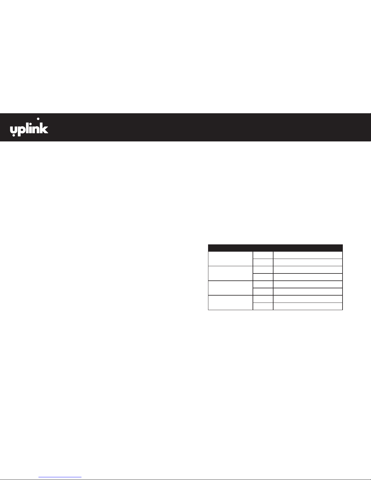
B. DIP Switch Settings
The 4530EX has a four-position dipswitch. The dipswitches function as follows:
SWITCH NO. SETTING FUNCTION
S1: Default Load OFF Normal Operations
ON Load Defaults
S2: OTA Operation OFF OTA conguration allowed
ON OTA conguration blocked
S3: Reserved OFF N/A
ON N/A
S4: LED Function OFF Normal Operations
ON RSSI Measurements
(INSTALLATION continued next page)
Page 8

4G PRIMARY CELLULAR
ALARM COMMUNICATOR
®
4530EX
13 14
INSTALLATION (cont.)
C. LEDs
Normal Mode: Upon initial power up, the 5 LEDs on the 4530EX will begin to
function as follows:
INSTALLATION (cont.)
RSSI Mode: When the 4530EX is placed in Received Signal Strength Indicator
(RSSI) Mode by turning Dipswitch S4 to ON, the ve LEDs indicate the follow
signal strength information:
,
GOOD
UNACCEPTABLE
MINIMUM
ACCEPTABLE
(INSTALLATION continued next page)
RECEIVED SIGNAL
STRENGTH
OFF
FLASH
ON
LED1
LED2
LED3
LED4
LED5
GREEN
>=-70dBm
GREEN
LED1
LED2
LED3
LED4
LED5
GREEN
>=-60dBm
GREEN
GREEN
LED1
LED2
LED3
LED4
LED5
GREEN
>=-90dBm
LED1
LED2
LED3
LED4
LED5
GREEN
>=-100dBm
LED1
LED2
LED3
LED4
LED5
RED
>=-110dBm
No Signal -All LED’s Off
*Recommended RSSI
LED1
LED2
LED3
LED4
LED5
GREEN
>=-80dBm
*
GREEN
GREEN
GREEN
00-25593-006rD
Page 9

4G PRIMARY CELLULAR
ALARM COMMUNICATOR
®
4530EX
15 16
INSTALLATION (cont.)
D. Locating and Installing the 4530EX
The 4530EX is housed in a plastic enclosure. The installer needs to supply DC
power from the panel via the AUX output, or battery, via a separate DC power
source. Input DC current is listed on page 25.
After carefully considering all of the issues outlined in Installations - General
Considerations, page 12, proceed as follows:
1. Separate the top and bottom of the enclosure by depressing the tab on
the bottom of the unit and then tilting the bottom of the plastic top
outward and up.
2. Connect the antenna that is supplied with the 4530EX. The Antenna
supplied may differ from the ones depicted in the gures in this manual.
3. Go to the red, 4-position Dipswitch as shown in Figure 1 and set the
dipswitch as appropriate for this installation. (See DIP Switch Settings,
page 12.)
4. Place Dipswitch #4 (S4) in the ON position. The LEDs are now operating
in RSSI Mode. Locate a good mounting position based on a good
Received Signal Strength Indication (RSSI). It is recommended that the
installation location demonstrate an RSSI of at least -80 dBm (two solid green
LEDs). The minimum acceptable RSSI is -90 dBm (1 solid green LED).
5. Position the bottom of the 4530EX enclosure where it will be installed.
Use four (4) #6 screws and mount the unit using the four holes in the
enclosure’s plastic bottom.
6. Make sure that the unit’s antenna is connected.
7. Connect the positive (+) and negative (-) terminals of the 12V DC power
supply to terminals DC+ and DC - respectively on the 4530EX.
8. Double check to make sure that the RSSI is still showing a good signal
strength level.
9. Before connecting the alarm panel and the 4530EX, rst:
a. Return Dipswitch #4 (S4) to the OFF position.
b. Disconnect the Positive and Negative connections to the
DC power source.
INSTALLATION (cont.)
FIGURE 1: Model 4530EX PC Board Details
STATUS LEDS
INPUT OUTPUT DC TERMINAL BLOCK
(INSTALLATION continued next page)
CAUTION: Incorrect Connections May Result in Damage to the Unit
DIP SWITCH
Page 10

4G PRIMARY CELLULAR
ALARM COMMUNICATOR
®
4530EX
17 18
INSTALLATION (cont.)
E. Connecting the 4530EX to the Alarm Panel
1. First, remove DC power from the 4530EX, and then proceed as follows:
2. Panel Connections
Connect the alarm panel’s telephone output to the 4530EX with an
appropriate cable. On the 4530EX’s side, the cable should use an RJ45 plug
and be connected into Jack JP3.
3. Output
The 4530EX has one relay output that can be used to activate an input on the
alarm panel or for other local purposes. Decide on how to use this output (see
section 6. Programming) then wire it from the terminal strip to the external panel
or device:
Output #1 Terminals: OUT1+ and OUT1-
The default state for this Output is as follows:
OUTPUT DEFAULT STATE DEFAULT DEFINITION
#1
Congurable - normally
closed
Loss of cellular service
See Figure 2 as an example of how to connect the 4530EX to the alarm panel.
IMPORTANT: Make all of the connections to the 4530EX in the powered down state. Once
all of the connections have been established, turn power on.
(INSTALLATION continued next page)
ALARM PANEL
Host Panel/DC In
TO RJ31X
Orange (#2)
Note: To use Uplink Remote,
connect wires #3 and #6 to the
panel as indicated in the
4530EX 4G Primary
Alarm Communicator
Yellow (#6)
Blue (#7)
Black (#3)
1
2
3
4
Switch# Setting
Off
On
Function
Normal Operations
Load Defaults
Off
On
Off
On
Off
On
Allow OTA Config
Block OTA Config
Reserved
Normal Operations
Normal Operations
RSSI Measurements
IN1+
IN1-
OUT1+
OUT1-
Uplink Remote manual.
INSTALLATION (cont.)
FIGURE 2: Connections between the 4530EX and the Alarm Panel
Page 11
4G PRIMARY CELLULAR
ALARM COMMUNICATOR
®
4530EX
19 20
(INSTALLATION continued next page)
INSTALLATION (cont.)
F. Conguring Input 1 (Via Over the Air programming)
Input 1 can be congured to perform one of four functions and is programmable Over-
The-Air via the Uplink Dealer web site.
1. Standard Input - (Default mode) This mode congures the unit to be tripped from a
DC voltage ranging from 9 V DC to 12 V DC or an open collector.
2. Timed Bell - This mode congures the unit to be tripped from a DC voltage
rang¬ing from 9 V DC to 12 V DC. The unit reads a pulsed voltage as a re signal
and a steady voltage as a burglary signal. It may be necessary to place a 1K Ohm
resis¬tor in parallel to prevent false alarms when using panels with supervisory
voltage on the bell circuit. Some panels with supervised bell circuits may require a
1K Ohm resistor in the circuit. Contact Technical Support for further details.
3. Sampled Siren* - This mode congures the unit to be tripped from a siren driver or
a panel with a built in siren driver. The unit reads a steady tone as a re signal and a
yelping tone as a burglary signal.
*NOTE: The input assumes that a speaker is connected to the panel. If you are not
using a speaker we recommend using a Timed Bell instead of Sample Siren. This is an
option on most panels.
INSTALLATION (cont.)
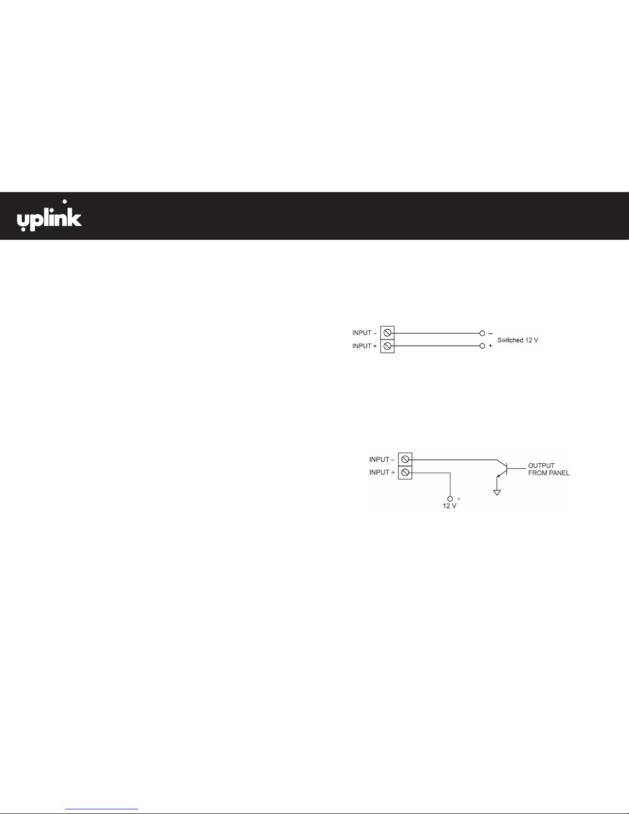
Input 1 if Standard Type
FIGURE 3: Wiring example for voltage trip
Voltage Trip - Input 1 if set for standard input can be tripped by applying 12 V to the +
input and 0 V to the - input. A signal must be continuously present for 500 ms.
FIGURE 4: Wiring example for open collector trip
Open Collector - Inputs 1 if set for standard input can be tripped by applying 12 V to the
+ input and the Open Collector output of the panel to the - input. A signal must be
continuously present for 500 ms.
Page 12

4G PRIMARY CELLULAR
ALARM COMMUNICATOR
®
4530EX
21 22
INSTALLATION (cont.)
H. Programming and Central Station Reporting
The following parameters can be congured from the dealer website “Programming” Menu:
1. Automated and On Demand Test Signals (Default = Weekly)
The Automated Test signal interval can be changed from the dealer website
to monthly, weekly, or daily. In addition, an immediate test signal can be generated.
2. Activate/Deactivate Output Relay
Output relay #1 can be activated or deactivated from the dealer website.
This feature allows the installer to test the correct operation of this output
when it is connected to the alarm panel.
3. Normal State of Output Relay (Default = #1 Energized Closed)
The normal state of the Output Relay can be changed from the dealer website.
4. Output Relay 1 Mapping (Default = #1 Loss of Cellular Service)
There are 6 Trouble states that can be declared by the 4530EX, and each of
these states can be programmed from the dealer website to activate the
Output Relay.
The 6 Trouble states are:
• Low DC Input Voltage
• Cable Supervision Trouble (Panel to 4530EX)
• Loss of Cellular Service
• 4530EX Disabled (via website command)
• Failure to receive ACK from Central Station
• Watchdog Circuit Trouble
5. Send Trouble Condition to Central Station “Specic Event Reporting” (Default = Low DC
Input Voltage)
Any or all of the Trouble Conditions detectable the 4530EX can be programmed to
report that condition (and its Restoral) to the monitoring Central Station.
INSTALLATION (cont.)
G. Activating the 4530EX
The 4530EX is programmed OTA (Over-the-Air) by accessing the Uplink Dealer website
or by calling Uplink Customer Service at 1-888-9UPLINK (1-888-987-5465).
New Dealer Enrollment:
For new dealers/customers, you must rst establish an account with Uplink by
visiting the Uplink website (www.uplink.com).
1. Enter the Login Name and Password. Wait about 20 seconds for the next web
page to completely load.
2. Under the Programming Tab, select “Activate Unit” from the menu choices.
3. Answer “Yes” to the question “I have read and I accept the terms of the Activation
Agreement”.
4. Enter the device serial number and select “Activate”.
5. If desired, enroll the unit in the Uplink Lifetime Guarantee program.
6. If you are offering Remote Services, enroll the unit in Uplink Remote.
7. You will be directed to the Edit Unit Settings page, where you will enter all
appropriate customer information.
8. From the Central Station Notication drop down menu, select the
appropriate format.
9. Enter the appropriate Central Station phone number and account number.
10. Congure the device to meet your install needs.
11. Select “Update”.
12. Unit must be powered to continue. From the “Programming” drop down menu,
select “Program Unit Over the Air”.
13. Set the appropriate Dialer Protocol, select Send.
14. From the “Test” drop down menu, select “Send Status Request Signal”.
15. Activation is complete once a successful test message is displayed. From the
“Signal History” drop down menu, select “Events Received”.
(INSTALLATION continued next page)
Page 13

4G PRIMARY CELLULAR
ALARM COMMUNICATOR
®
4530EX
23 24
INSTALLATION (cont.)
I. Default Event/Email Messages
Email and Text Messaging will only be available for Status events (e.g., Low DC input
Voltage, Test, etc.). Events transmitted from the premises alarm panel via the 4530EX’s
Primary function will not be sent out by email or text messaging.
J. Completing the Installation and Testing
Once the physical installation is completed, the unit is activated from the dealer
website, and programming changes are made, test the 4530EX along with the alarm
panel to ensure everything is functioning properly.
Test the following:
a. Check to see that all 5 LEDs are green. The rst 4 LEDs should be solid
green, and the 5th LED should be ashing green.
b. Trip an alarm on the alarm panel. Check that the 4530EX has correctly
intercepted the panel’s digital dialer output and reported the event to the
central monitoring station.
c. If using the Output Relay on the 4530EX go back to the dealer website and
use the Switch Output Relay command to test the relay. Make sure the
premises alarm panel properly detects the relay’s change of state and that
it reports the proper event to the monitoring central station.
d. Finally, remove DC Power from the 4530EX and trip an alarm on the premises
alarm panel. Conrm that the panel detects loss of its communication path
and alarms appropriately (local).
e. Reconnect DC Power to the unit and verify proper handling of the alarm
from the panel.
See Appendix A for a list of Contact ID format, SIA format and Modem IIe/IIIa/IIIa2 event codes
generated by the 4530EX that can be sent to the central station receiver.
See Appendix B for a list of the default event codes transmitted by the 4530EX.
The 4530EX supports Pulse 4/2 with any combination of :10, :20, or :40 PPS. Two round or
checksum, 1400 Hz or 2300 Hz handshake.
4G PRIMARY CELLULAR
ALARM COMMUNICATOR
®
4530EX
Page 14

4G PRIMARY CELLULAR
ALARM COMMUNICATOR
®
4530EX
25 26
SPECIFICATIONS
DIGITAL DIALER INTERFACE
Format Compatibility Contact ID, SIA, Modem IIe/IIIa/IIIa2, Pulse
4/2 (:10, :20, or :40 PPS)
Connector RJ45 and screw terminals
Simulated telco line voltage 48 V DC On-Hook
Dial tone 350 + 440 Hz +/- 0.2%
Receive level minimum - 45 dBm, 20 dBm S/N
Line impedance 600 ohms
Ringer Equivalence 0.3 REN
Mode Loop start. 26 mA typical
POWER REQUIREMENTS
Input Voltage 12V DC
Normal Current (On Hook) 125 mA
Maximum Current (Off Hook) 600 mA
Radio during Transmission
- Average Current
- Peak Current
215 - 250 mA
1.3 – 1.5 A
UL Power Requirements Uninterruptable Class 2 power supply
12V DC/1.2 A
SPECIFICATIONS (cont.)
RADIO
Frequencies 850/1900 MHz
Sensitivity -106 dB (typical)
ENVIRONMENTAL
Temperature Range -30° to +70° C
Humidity 0 to 95% non-condensing
PHYSICAL
Height 2.5 inches
Width 5.4 inches
Depth 10.5 inches
Page 15

4G PRIMARY CELLULAR
ALARM COMMUNICATOR
®
4530EX
27 28
APPENDIX A:
CONTACT ID, SIA EVENT, AND
MODEM IIe/IIIa/IIIa2 CODES
Following is a list of event codes that can be sent to the central station receiver for
events generated by the 4530EX:
EVENT DESCRIPTION CONTACT ID
EVENT CODE
SIA DC-03
EVENT CODE
MODEM IIe/
IIIa/llla
2
AC Fail E301 AT 48
AC Restoral R301 AR 49
Alarm (generic) E140 UA 10
Burglary Alarm E130 BA 10
Burglary Restoral R130 BR 12
Burglary Tamper E137 TA 10
Burglary Tamper Restoral R137 TR 12
Closing R400 CL 32
Fire Alarm E110 FA 0B
Fire Restoral R110 FR 0E
Fire Supervisory E200 FS 11
Fire Supervisory Restoral R200 FJ 12
High Temperature E158 KA 10
High Temperature Restoral R158 KR 12
Holdup Alarm E122 HA 10
Holdup Restoral R122 HR 12
Low Battery E302 YT 4B
Low Battery Restoral R302 YR 4C
Low Temperature E159 ZA 10
APPENDIX A:
CONTACT ID, SIA EVENT, AND
MODEM IIe/IIIa/IIIa2 CODES
(cont.)
EVENT DESCRIPTION CONTACT ID
EVENT CODE
SIA DC-03
EVENT CODE
MODEM IIe/
IIIa/llla
2
Low Temperature Restoral R159 ZR 12
Medical Alarm E100 MA 10
Medical Restoral R100 MR 12
Opening E400 OP 2F
Panic Alarm E120 PA 10
Panic Restoral R120 PR 12
Phone Fail E350 LT 44
Phone Restoral R350 LR 45
Radio Supervision Lost E355 YC 11
Radio Supervision Restoral R355 YK 12
Restoral (generic) R140 UR 12
Service Completed R616 YZ 12
Service Required E616 YX 11
Telco Line Fail E350 LT 44
Telco Line Restoral R350 LR 45
Test E602 TX 33
Trouble (generic) E300 UT 11
Trouble Restoral (generic) R300 UR 12
Trouble, System Peripheral E330 ET 11
Trouble Restoral, System
Peripheral
R330 ER 12
Page 16
4G PRIMARY CELLULAR
ALARM COMMUNICATOR
®
4530EX
29 30
APPENDIX B:
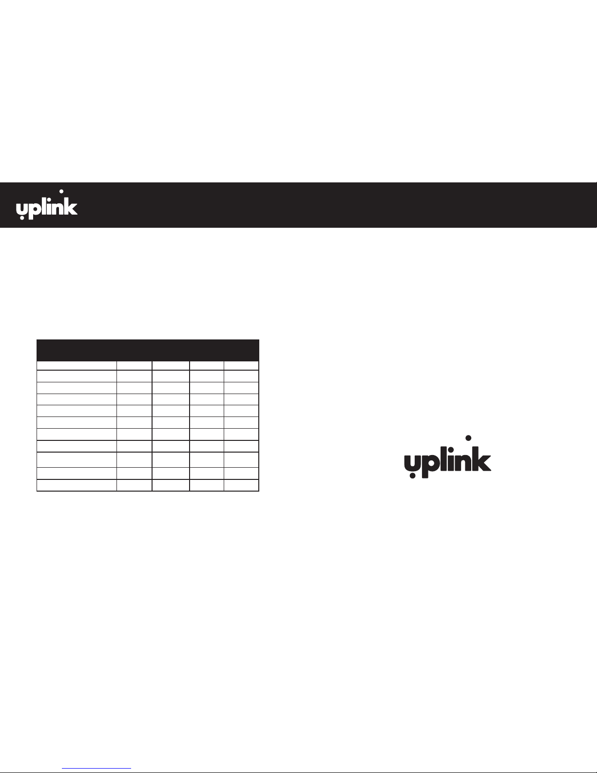
4530EX DEFAULT EVENT CODES
The 4530EX is defaulted to send both the Alarm/Trouble condition and the Restoral
condition for all of the events listed below. Reporting of individual events can be
controlled from the Dealer Website.
Following is a list of the default event codes sent by the 4530EX:
EVENT DESCRIPTION CONTACT
ID EVENT
CODE
SIA DC-03
EVENT
CODE
MODEM
IIe/IIIa/
llla
2
ZONE NO.
REPORTED
Low DC Voltage E302 YT 4B 240
Low DC Restoral R302 YR 4C 240
Cable Supervision Trouble E616 YX 11 242
Cable Supervision Restoral R616 YZ 12 242
Cellular Service Loss E355 YC 11 243
Cellular Service Restoral R355 YK 12 243
4530EX UNIT DISABLED E616 YX 11 245
4530EX UNIT RESTORAL R616 YZ 12 245
WATCHDOG CIRCUIT
TROUBLE
E616 YX 11 246
Watchdog Circuit Restoral R616 YZ 12 246
Test E602 TX 33 000
UPLINK 4530EX 4G PRIMARY ALARM COMMUNICATOR
INSTALLATION, OPERATION AND PROGRAMMING GUIDE
© 2013 Uplink Security, LLC. All rights reserved. Uplink is a trademark of Uplink
Security, LLC.
UPLINK SECURITY, LLC.
3330 CUMBERLAND BLVD., SUITE 700, ATLANTA, GA 30339
888-987-5465 (888-9-UPLINK)
WWW.UPLINK.COM
®
 Loading...