

Page 1
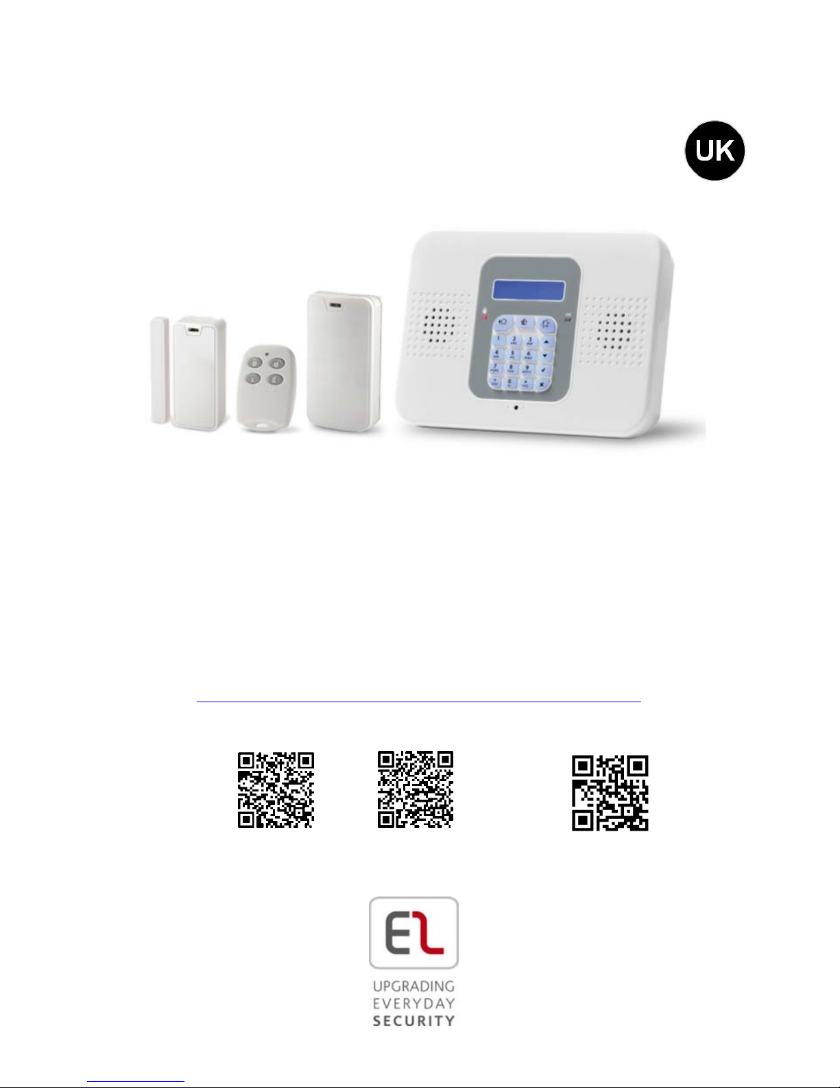
Quick Start Guide
Visit us on the Web: www.riscogroup.com
For detailed installation and system information,
refer to the full installation manual at:
http://www.riscogroup.com/products/products/953
iOS app Android app RISCO Group website
SecuPlace WiFi
Page 2

2
Table of Contents
GETTING STARTED ....................................................................................................... 4
KIT COMPONENTS ............................................................................................................. 4
EXPANDING YOUR SYSTEM .................................................................................................. 4
SYSTEM INSTALLATION ....................................................................................................... 4
IMPORTANT SAFETY PRECAUTIONS ............................................................................ 5
INITIAL SYSTEM SETUP ................................................................................................ 6
STEP 1: SIM INSTALLATION AND CONTROL PANEL WIRING ......................................... 7
INSTALLING THE SIM CARD ................................................................................................. 7
WIRING AT THE CONTROL PANEL ......................................................................................... 8
STEP 2: INSTALLING THE CONTROL PANEL ................................................................. 11
MOUNTING GUIDELINES .................................................................................................. 11
INSTALLATION PROCEDURE ............................................................................................... 12
STEP 3: POWERING-UP THE CONTROL PANEL ............................................................ 13
STEP 4: SELECTING A LANGUAGE ............................................................................... 14
STEP 5: REGISTERING COMPONENTS ......................................................................... 15
REGISTERING KIT COMPONENTS ........................................................................................ 15
LISTING OF COMPONENT/ ZONE INFORMATION .................................................................... 15
REGISTERING ADDITIONAL COMPONENTS ............................................................................ 16
REGISTERING KEYFOBS ..................................................................................................... 16
DELETING COMPONENT REGISTRATIONS.............................................................................. 17
DELETING KEYFOB REGISTRATIONS ..................................................................................... 17
STEP 6: INSTALLING KIT COMPONENTS ..................................................................... 18
PRE-INSTALLATION PLANNING ........................................................................................... 18
INSTALLING THE MAGNETIC DOOR / WINDOW CONTACT DETECTOR......................................... 19
Mounting Guidelines ............................................................................................. 19
Installation Procedure ........................................................................................... 20
INSTALLING THE PIR DETECTOR ......................................................................................... 23
Mounting Guidelines ............................................................................................. 23
Installation Procedure ........................................................................................... 24
STEP 7: TESTING THE SYSTEM .................................................................................... 26
PERFORMING A KEYFOB TEST ............................................................................................ 26
PERFORMING A WALK TEST FOR DETECTORS ........................................................................ 26
STEP 8: DEFINING SYSTEM USERS .............................................................................. 27
Page 3

3
A
SSIGNING, EDITING, AND DELETING USERS (USER CODES).................................................... 28
DESIGNATING A FOLLOW ME NUMBER .............................................................................. 29
STEP 9: ESTABLISHING SYSTEM COMMUNICATION .................................................. 29
COMMUNICATION CHANNELS ........................................................................................... 29
Connecting to GPRS / GSM ................................................................................... 29
Editing the APN ..................................................................................................... 30
CONNECTING TO WIFI..................................................................................................... 31
Selecting your WiFi Network: ............................................................................... 31
Changing the WiFi Network .................................................................................. 31
STEP 10: CONNECTING TO RISCO CLOUD .................................................................. 32
REGISTERING TO RISCO CLOUD ........................................................................................ 32
LOGGING IN TO RISCO CLOUD ......................................................................................... 33
OPERATING THE SYSTEM .......................................................................................... 34
BEFORE YOU START USING THE SYSTEM ............................................................................. 34
Describing the Control Panel Keypad ................................................................... 34
Describing the Control Panel LEDs ........................................................................ 35
Describing the Keyfob LED .................................................................................... 35
Describing the PIR Detector LED ........................................................................... 35
Describing User Commands .................................................................................. 36
Describing Arming Modes .................................................................................... 36
PERFORMING COMMANDS FROM CONTROL PANEL AND KEYFOB ............................................. 37
SENDING SMS COMMANDS ............................................................................................. 38
USING THE SMARTPHONE AND WEB APPLICATIONS .............................................................. 39
Smartphone App ................................................................................................... 39
Web Application ................................................................................................... 39
TROUBLESHOOTING ................................................................................................. 40
SYSTEM MAINTENANCE — BATTERY REPLACEMENT ................................................ 43
REPLACING KEYFOB BATTERIES ......................................................................................... 43
REPLACING COMPONENT BATTERIES .................................................................................. 44
PRODUCT SPECIFICATION ......................................................................................... 45
CERTIFICATION AND STANDARDS ............................................................................. 47
RISCO GROUP LIMITED WARRANTY ......................................................................... 48
CONTACTING YOUR ENGINEER ................................................................................. 51
CONTACTING RISCO GROUP ..................................................................................... 52
Page 4
4
Getting Started
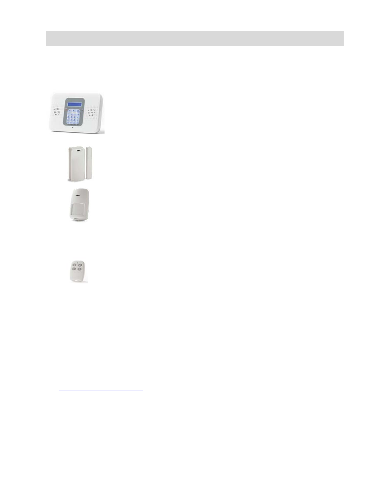
Kit Components
Control Panel
The control panel communicates with all system
detectors and accessories, with the alarm receiving
centre, and with users via Cloud-based Smartphone
and Web-browser applications.
Detectors
Detectors generate alarm events upon intrusion
detection. Magnetic door / window contact detectors
serve to protect doors and windows, while PIR
(Passive Infra-Red) motion detectors serve to protect
designated zones. A large selection of other (optional)
RISCO Group detectors can also be installed.
Keyfobs
Keyfobs are hand-held mini-remote control
transmitters that enable arming / disarming the system,
sending panic alarms and medical assistance alarms.
Expanding your System
This kit contains the necessary components required to operate your
security alarm system, however you can enhance and customize your
system by adding additional components – up to a maximum of 32
detectors and sensors, 19 keyfobs, 4 repeaters (range extenders), 4 keypads,
and 1 alarm sounder. Visit the RISCO Group website for more information
at: www.riscogroup.com. Also, see Product Specification on page 45 for
further system details.
System Installation
It is recommended to have your system installed by a professional, such as
an alarm system engineer or electrician.
Page 5
5
Important Safety Precautions
WARNING: Installation or usage of this product that is not in
accordance with the intended methods as described in
the instructional materials and by the supplier can
result in damage, injury, or death.
WARNING: Make sure this product is not accessible by children and
those for whom system operation is not intended.
WARNING: Do not ever attempt to repair your wireless security
alarm system by yourself, as doing so could result in
damage, injury or death. Always contact your
engineer / supplier for repair or maintenance issues.
WARNING: The main panel should be connected to an
easily-accessible electrical wall outlet or disconnection
device, such as a circuit breaker.
WARNING: Electrical power connections to the control panel should
be according to applicable electrical code and
regulations.
WARNING: Do not attempt to replace the battery in the control panel
yourself – always contact your engineer / provider.
WARNING: Ensure a battery is replaced with the correct type and
polarity. Do not recharge, disassemble, deform, expose
to high heat, or incinerate batteries. Failure to observe
these warnings may result in explosion, fire, damage,
injury, or death.
CAUTION: Always dispose of used batteries according to applicable
law and regulations.
Page 6

6
Initial System Setup
The following steps are required to initially set up your system for
operation:
Step 1: SIM Installation and Control Panel Wiring
Step 2: Installing the Control Panel
Step 3: Powering Up the Control Panel
Step 4: Selecting a Language
Step 5: Registering Components
Step 6: Installing Kit Components
Step 7: Testing the System
Step 8: Defining System Users
Step 9: Establishing System Communication
Step 10: Connecting to RISCO Cloud
Page 7
7
Step 1: SIM Installation and Control Panel Wiring
WARNING: Make sure the control panel is NOT connected to an
electrical power supply when performing SIM
installation and wiring.
WARNING: Make sure to comply with all applicable electrical code
and regulations.
CAUTION: If your system does not have a SIM card pre-installed,
install it before applying electrical power to the control
panel.
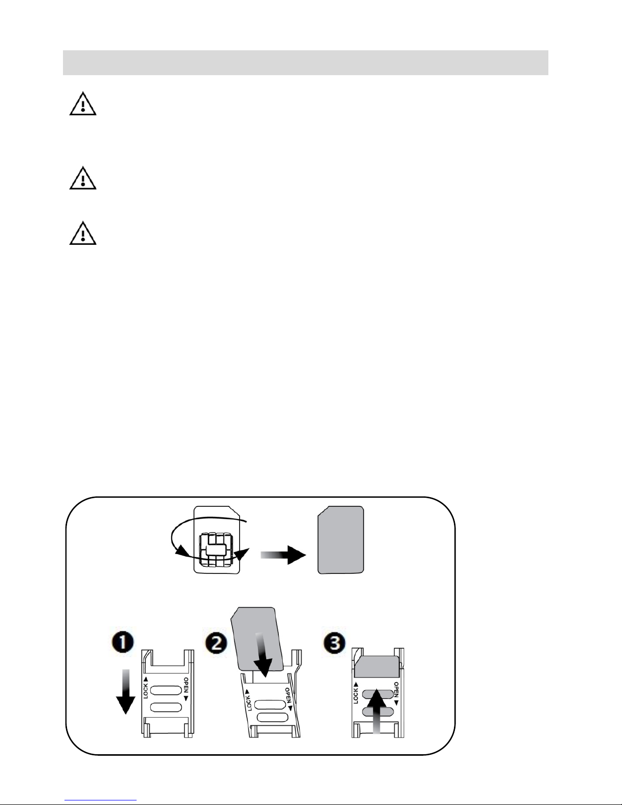
Installing the SIM Card
A SIM card must be installed to enable GPRS communication. Access is
from the back-side of the control panel, which enables the SIM card to be
installed without having to open the panel (see illustration on page 9).
Alternatively, if you have any wiring to be done at the control panel, when
you open the control panel for the wiring tasks, you can also install the SIM
card at the same time.
To install a SIM card:
Page 8
8
Wiring at the Control Panel
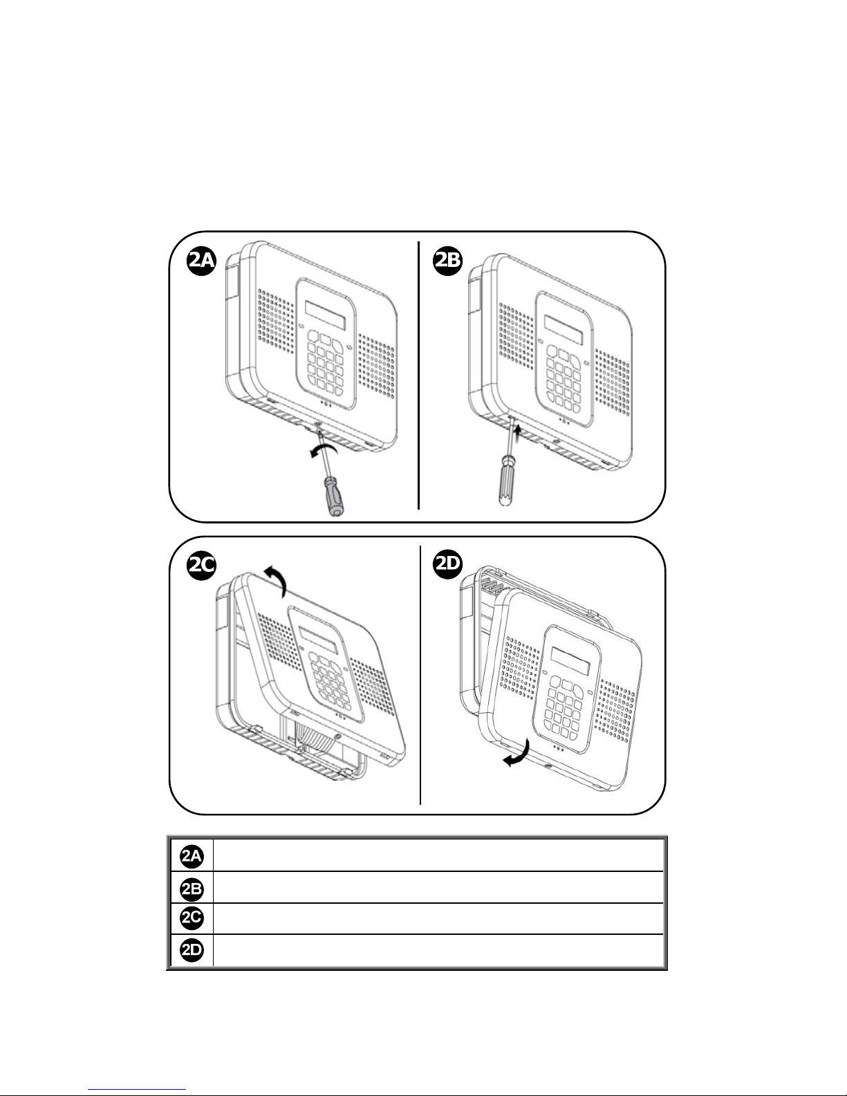
To perform wiring at the control panel:
1. Make sure the control panel is NOT connected to an electrical
power supply, and then open it as follows; both covers remain
connected to each other with a ribbon cable (do not detach):
Remove and retain the screw on the cover.
Release the right and left tabs (left location shown).
Detach the cover from the bottom-facing side.
Detach the cover from the top-facing side.
Page 9
9
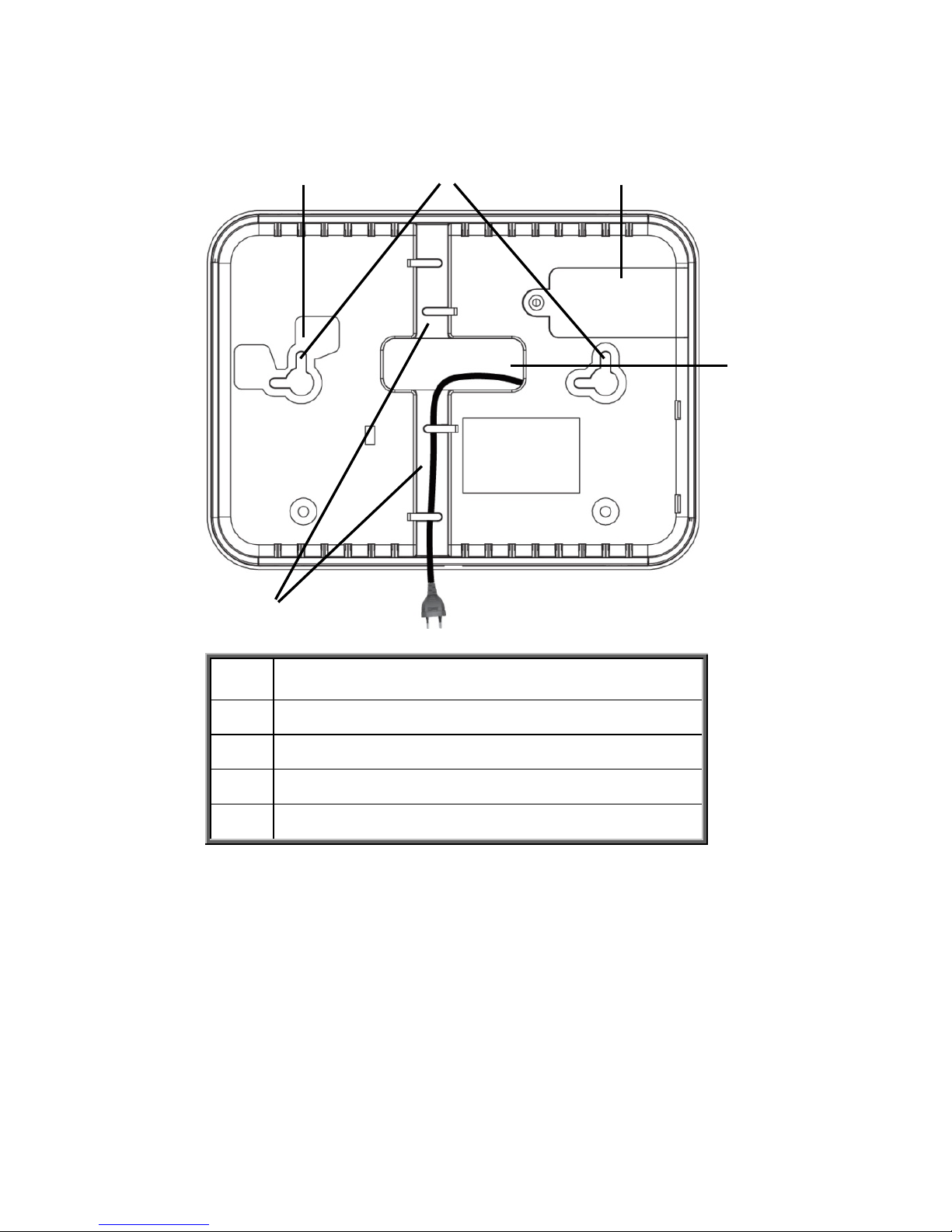
2. At the back side of the control panel, route the AC power cable
through the wiring outlet:
Tamper switch location (on opposite side)
Screw mounting grooves
SIM card access cover
Wiring outlet
Wiring ducts
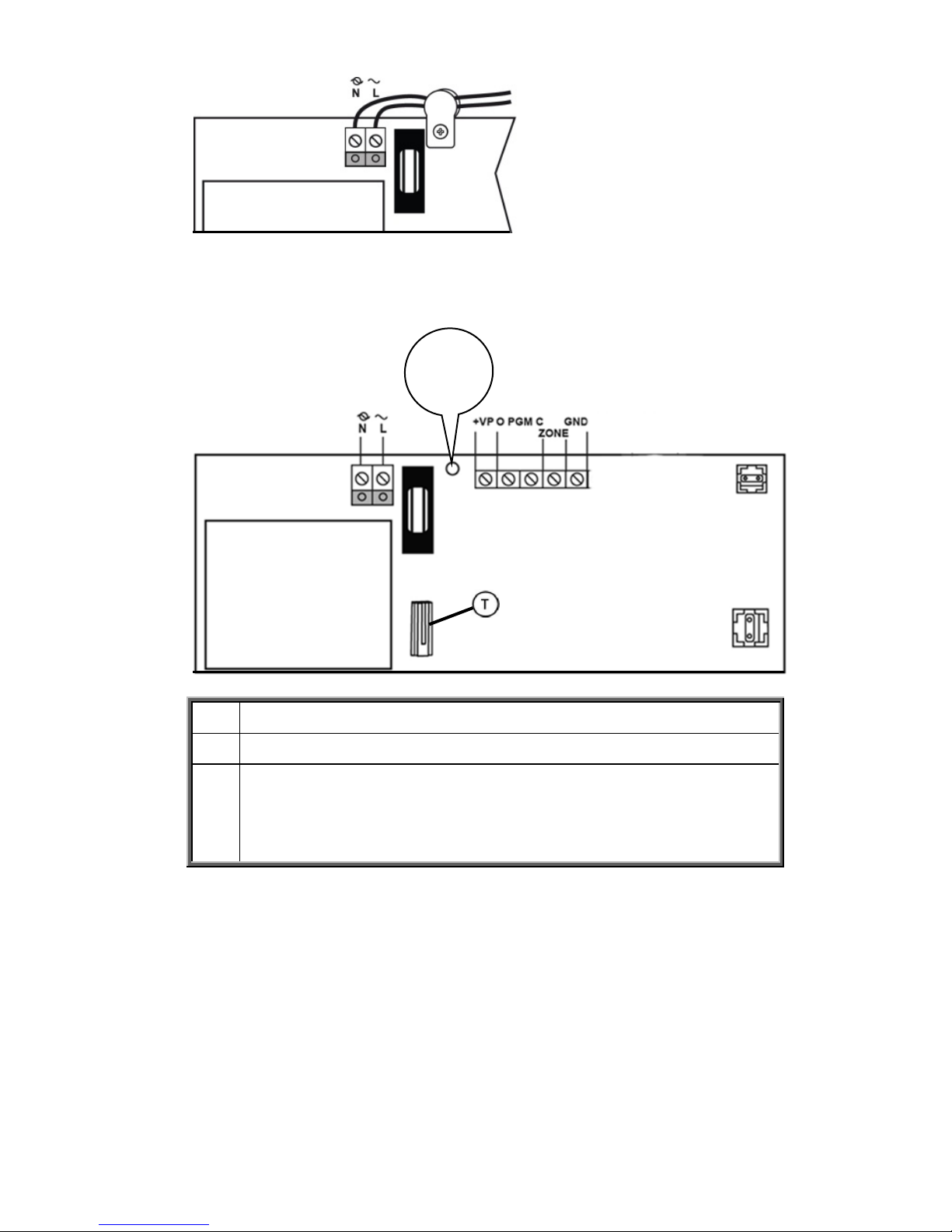
3. Connect the AC power cable leads to the AC terminals, ensuring
the correct live [L] and neutral [N] wiring, as shown in the
following illustration on page 10.
NOTE: For the AC power cable wiring colors, refer to the
applicable electrical code for the country / region of
installation.
4. Secure the AC power cable onto the PCB using the provided cable
clamp, screw and washer and then route the cable through one of
the wiring ducts:
Page 10
10
5. At the terminal block connect wire leads for the relevant
connections, as required:
AC power supply terminals
Cable clamp
Terminal block. Connection terminals from left to right:
external module, PGM, zone (for a single hard-wired
peripheral), GND.
6. If the SIM card has not been installed yet, install it now directly
onto the PCB in order to enable GPRS / GSM communication
(see Installing the SIM Card, page 7).
7.
When all control panel wiring and the SIM card installation tasks
are finished, close up the control panel casing. Make sure the tabs
on the cover snap into place into their respective grooves, and then
re-install the small screw back onto the front cover.
8. Mount the control panel onto the wall (see Step 2: Installing the
Control Panel, page 11).
Page 11

11
Step 2: Installing the Control Panel
Mounting Guidelines
When installing, make sure the control panel is:
Accessible to all external connections for electrical power supply
and additional (non-kit) RISCO Group components.
In a central location, in relation to the wireless components your
system will be using, with a minimal distance from the
components
At a location where the GSM signal is adequately strong
Near the entry/exit door of the secured site, in order to allow
enough time for leaving after arming the system
Out-of-sight of would-be intruders, and out-of-reach of
unintended users (such as children)
At a location with a minimal number of obstacles between the
control panel and the detectors. Metal-based construction
materials, such as thick or steel-reinforced concrete walls can
reduce the RF signal strength.
Page 12
12
Installation Procedure
WARNING: Make sure the control panel is NOT connected to any
electrical power supply.
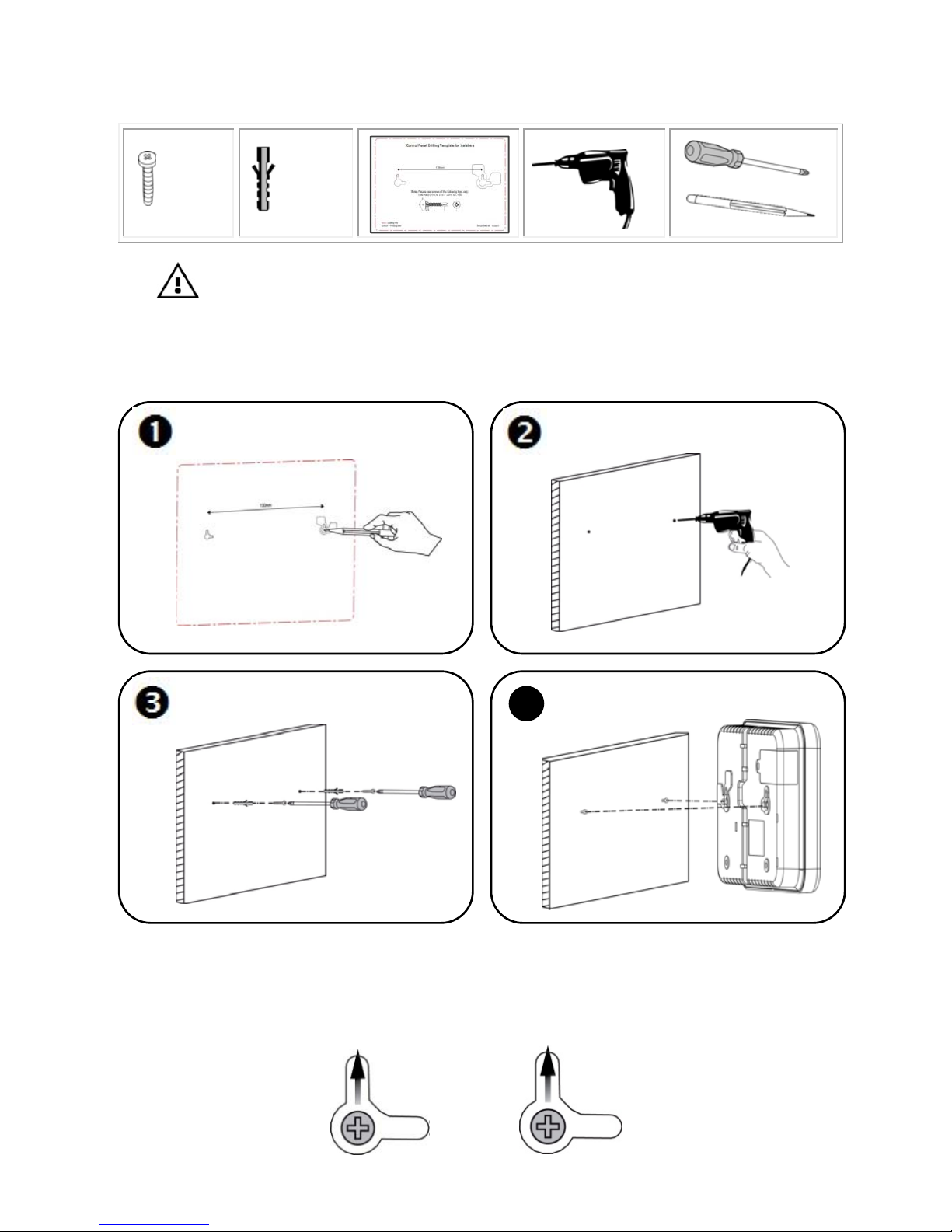
To install the control panel:
IMPORTANT: When mounting, although the screws enter the control
panel’s elbow grooves in the center as shown below, the screw holes /
screws must be positioned at the upper-most location on the elbow grooves:
4
4
X 2
X 2
Page 13

13
Step 3: Powering-Up the Control Panel
After performing all wiring tasks at the control panel, installing the SIM
card, and installing the control panel, you can now power-up the control
panel.
NOTE: After initial power-up, any subsequent removal of the control panel
from the wall will trigger a tamper alarm.
NOTE: Ignore any low battery message that may display while powering-up.
This indicates the control panel backup battery needs recharging, however the
system will operate normally using its AC power supply.
To power-up the control panel:
Apply electrical power to the control panel with the AC power cable,
or at the circuit breaker switch; you will be prompted by the control
panel display to select a language (see Step 4).
Page 14
14
Step 4: Selecting a Language
Upon initial control panel power-up, you will be prompted to select the
language and default options.
To select a language:
1. At first installation, after control panel power-up, SELECT
LANGUAGE displays on the keypad.
2. Use to scroll to the language you would like to display at
the control panel, and then press .
3. Press to set for www.riscocloud.com (default);
INITIALIZING, and then DISARMED display.
IMPORTANT: If SYSTEM NOT READY, SYSTEM TROUBLE or TAMPER
ALARM also display, they indicate there are trouble messages (use to
scroll and view). However, these messages could be due to reasons which
may resolve automatically after a short time, thus it is recommended to
wait until after you have completed all (10) initial system setup steps before
troubleshooting.
Page 15
15
Step 5: Registering Components
All components used in your system (detectors, keyfobs, and other wireless
devices) must be registered in order to be recognized by the system.
Registering Kit Components
Your kit comes with pre-registered components. Perform the following to
complete the registration process.
NOTE: For the kit-supplied keyfob, see Registering Keyfobs, page 16.
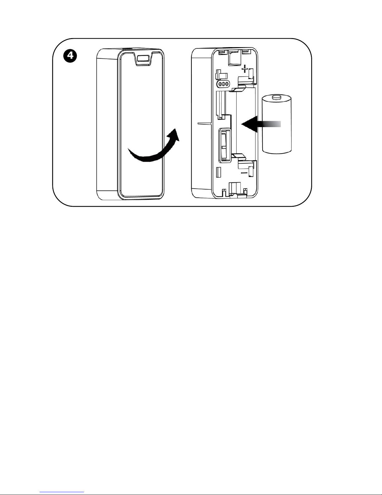
1. Open each component (see the illustrations on pages 18 and 21)
2. Remove the battery protector strips / install the batteries; a chime
sounds indicating the control panel recognizes the component.
3. Put the component covers back on.
NOTE: The factory-assigned zone numbers for the kit-supplied
components are listed below. It is recommended to write
down their locations / descriptions as well.
Listing of Component/ Zone Information
It is important to retain this listing for future reference, for example, when
performing a walk test, or when bypassing zones.
Component name & model
Zone number /
keyfob number
Zone location & description
(for keyfobs, list the
users who retain them)
Magnetic contact detector
(kit-supplied)
1
PIR detector (kit-supplied) 2
Keyfob (kit-supplied) Keyfob 1
Page 16

16
Registering Additional Components
For additional components added to your system, register them as follows:
NOTE: For additional keyfobs, see Registering Keyfobs, page 16.
To register additional components:
1. Remove the component cover.
2. At the control panel, press and hold for about 3 seconds
(disregard the ENTER USER CODE message) until REGISTER and
TRANSMIT 1 display.
3. Now remove the battery protector strip or plastic wrapping (if you
have to remove the battery in order to do this, make sure the
battery is then inserted in the component with the correct polarity);
TRANSMIT 2 displays.
4. Press the component’s tamper switch and then release it; the
(automatically-generated) zone number and SAVE? display.
IMPORTANT: In the listing provided write down the zone
number, component name, and its location / description.
5. Press to save the registration, or press to cancel.
6. Attach the (registered) component’s cover correctly in place.
7. Repeat this procedure from step 3 to register the next component,
or if finished, press to exit the registration mode.
Registering Keyfobs
To register keyfobs:
1. At the control panel, press and hold for about 3 seconds
(disregarding the ENTER USER CODE message) until REGISTER
and TRANSMIT 1 display.
2. Press any keyfob button; REGISTER and TRANSMIT 2 display.
3. Press the same keyfob button again; the keyfob number and
SAVE? display.
IMPORTANT: In the listing provided write down the keyfob
number, and the user who retains it.
Page 17

17
4. Press to save the registration, or press to cancel.
5. Register the next device, or if finished, press to exit the
registration mode.
Deleting Component Registrations
If you no longer use a system component, you must “delete” its registration
to the control panel.
To delete a component registration:
1. Remove the cover from the component.
2. At the control panel press for about 3 seconds until DELETE
and TRANSMIT 1 display.
3. Press the component’s tamper switch; DELETE OK? displays.
4. Press to delete the registration, or press to cancel the
deletion request.
Deleting Keyfob Registrations
If you no longer use a keyfob, you must “delete” its registration to the
control panel.
To delete a keyfob registration:
1. At the control panel, press for about 3 seconds until DELETE
and TRANSMIT 1 display.
2. Press any button on the keyfob twice; the keyfob number and
DELETE OK display.
3. Press to delete the registration, or press to cancel the
deletion request.
Page 18

18
Step 6: Installing Kit Components
Pre-Installation Planning
Before installing system components, to ensure optimal system
performance, determine which areas need to be protected and the best
locations for installing the components.
Page 19
19
Installing the Magnetic Door / Window Contact Detector
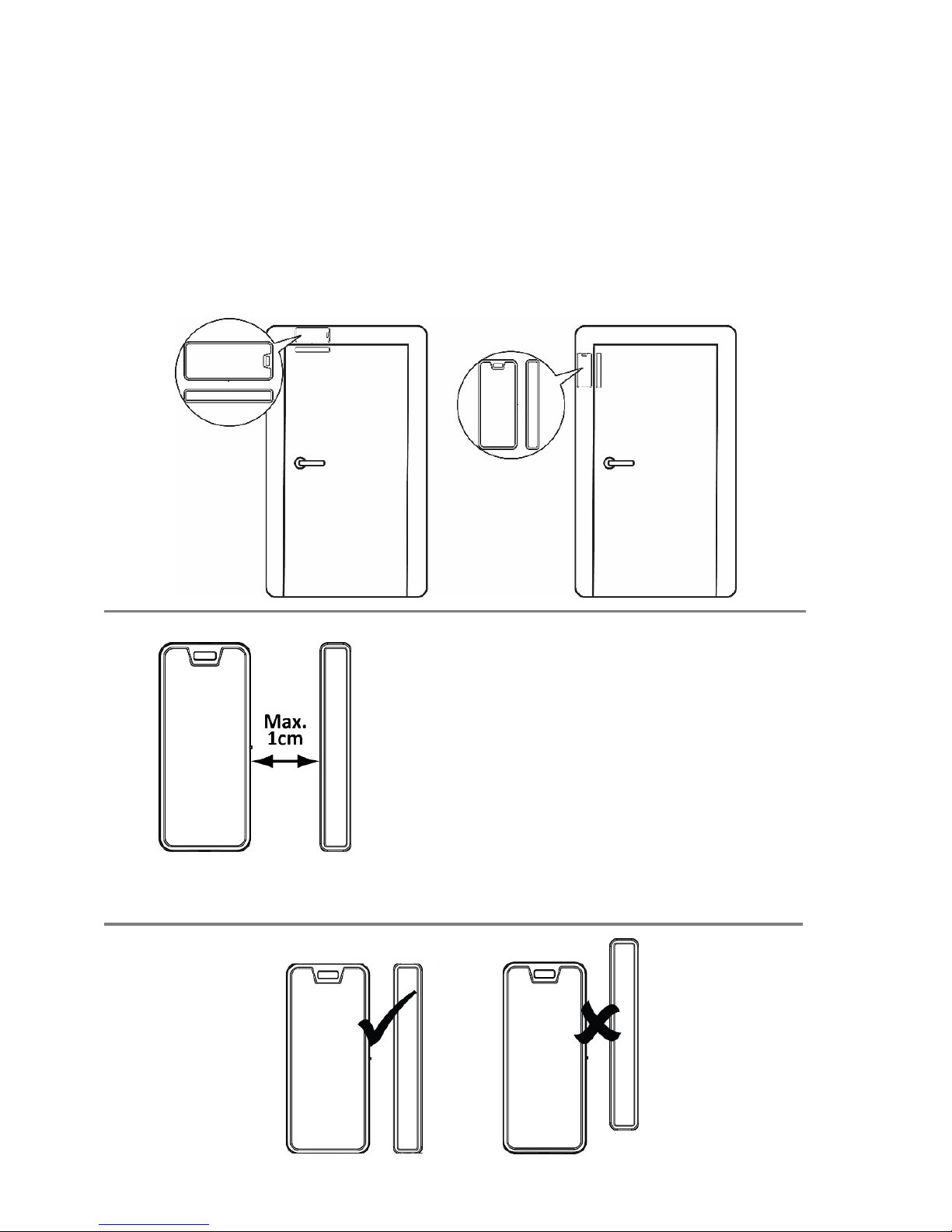
The magnetic door / window contact detector has two parts – a transmitter,
and a magnet. It can be installed at the entry / exit door of a secured site, to a
window, a sliding door, or at any similar entrance that could be accessed by
an intruder.
Mounting Guidelines
Transmitter Magnet
NOTE: It is recommended to
affix the transmitter to the
non-moving part of the door
or window (such as to the
door frame / window frame),
and to affix the magnet to the
moving part.
Page 20
20
Installation Procedure
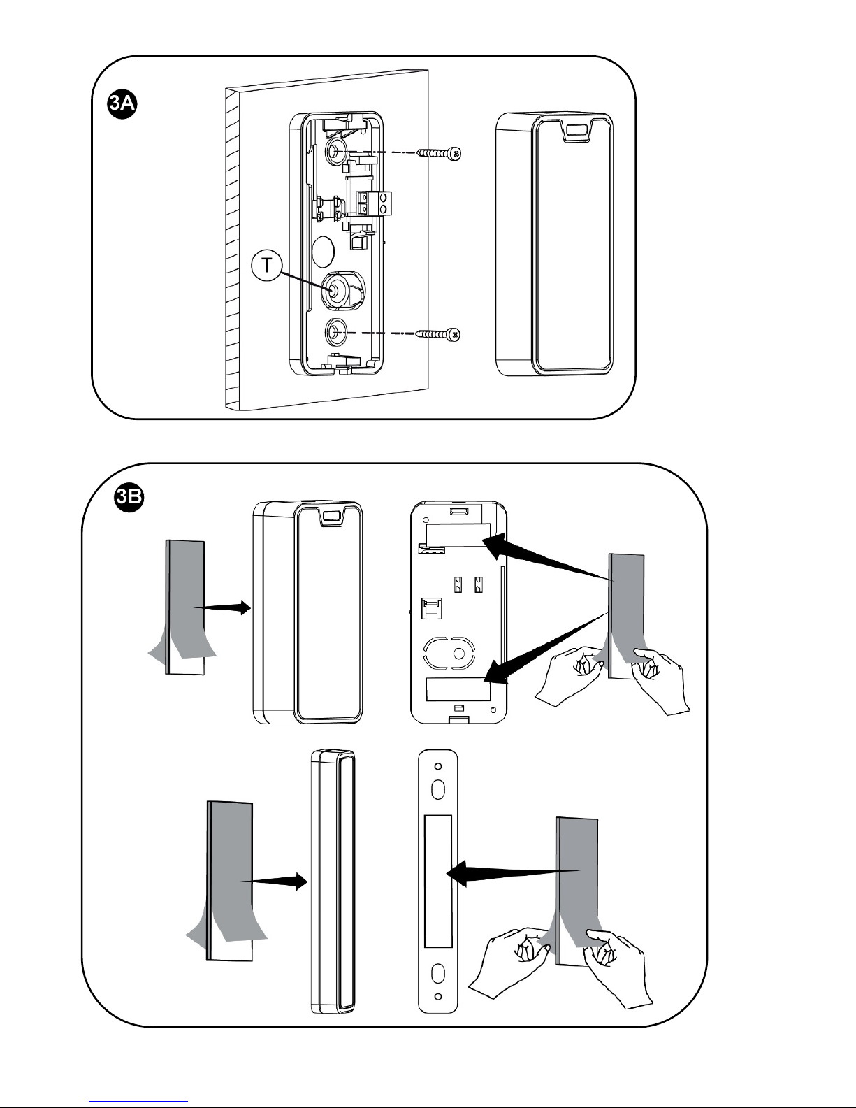
NOTE: If the transmitter is installed using adhesive strips, the back tamper
switch will not be operational.
NOTE: For installing the transmitter with adhesive strips, skip to step 3B in
the following procedure.
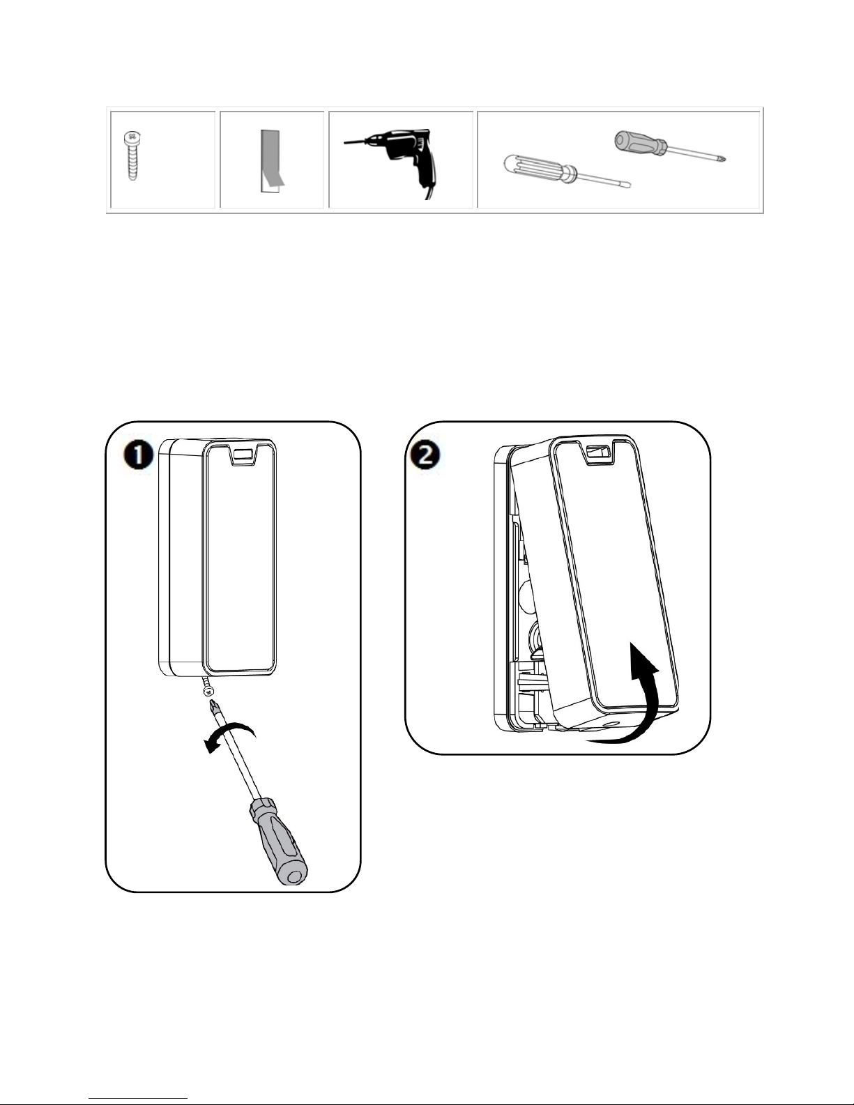
To install the transmitter and magnet:
X 4
Page 21
21
-OR-
Page 22
22
Page 23
23
Installing the PIR Detector
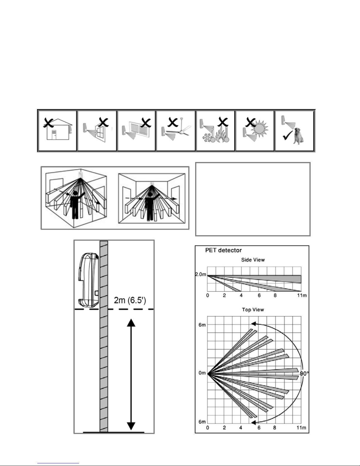
The wireless PIR (Passive Infra-Red) detector detects movement for up to
11 metres (36 feet) indoors. The Pet immunity (PI) model is designed to not
trigger alarms by small pets that weigh up to 36 kilograms (80 pounds).
Mounting Guidelines
Avoid mounting a PIR PI
detector in a location where
a pet can come within reach
of the detector by climbing
on furniture or other
objects.
Page 24
24
Installation Procedure
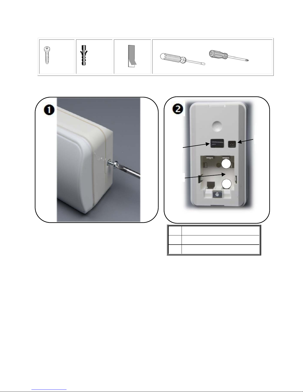
To install a PIR detector:
A
Tamper switch
B
DIP swtich
C
Battery holder
4
X 4
X4
+
-
A
B
C
Page 25
25
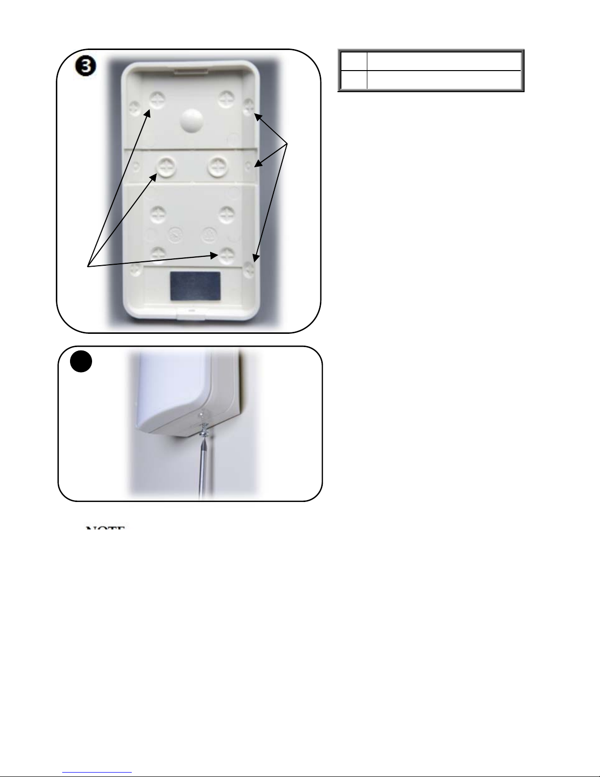
D
Wall mount
E
Corner mount
NOTE:
Retain the screw for use when re-installing the PCB
An additional battery (purchased separately) can also be used to
extend the operational duration (size ½ AA, 3.6 V, lithium). Check the
RISCO Group website for information on battery updates.
4
D
E
Page 26

26
Step 7: Testing the System
It is recommended to test all system components (kit-supplied and
additional) to ensure correct operation.
Performing a Keyfob Test
Test keyfobs by pressing the arming / disarming buttons to observe whether
the respective chimes are heard, and whether the control panel display
indicates arming/disarming.
Performing a Walk Test for Detectors
For PIR and magnetic door / window contact detectors, perform a walk test.
This entails arming the system, then walking through all PIR-protected
zones and also opening all magnetic contact-protected doors and windows
– with the intent of triggering the alarms, to ensure the components are
working correctly.
To perform a walk test:
1. At the control panel, press .
2. Enter the engineer code (default is 1111) or master code (default is
1234).
3. Enter 7 > 0 > 6; all registered PIR and magnetic door / window
contact detectors display chronologically, according to when
registered. Scroll using to view them all.
NOTE: Before doing the walk test, keep in mind that a PIR
detector needs 90 seconds for warming up for after battery
installation.
4. Make sure nobody is in the armed zones when you initiate the
walk test, otherwise it may take up to 4 minutes to reset the PIRs.
5. Walk through all armed zones to trigger alarms for each PIR
detector, and also open the doors/windows for each magnetic
contact detector. When the system receives a transmission signal
from a detector, it will no longer display on the control panel
(indicating the detector is working correctly).
Page 27
27
Step 8: Defining System Users
The system supports up to 31 users, and each user needs to be assigned a
unique 4-digit user code. A valid user code is required to perform most
system operations.
NOTE: Controlled codes communicate system commands to the alarm
receiving centre, whereas non-controlled codes do not communicate system
commands to the alarm receiving centre.
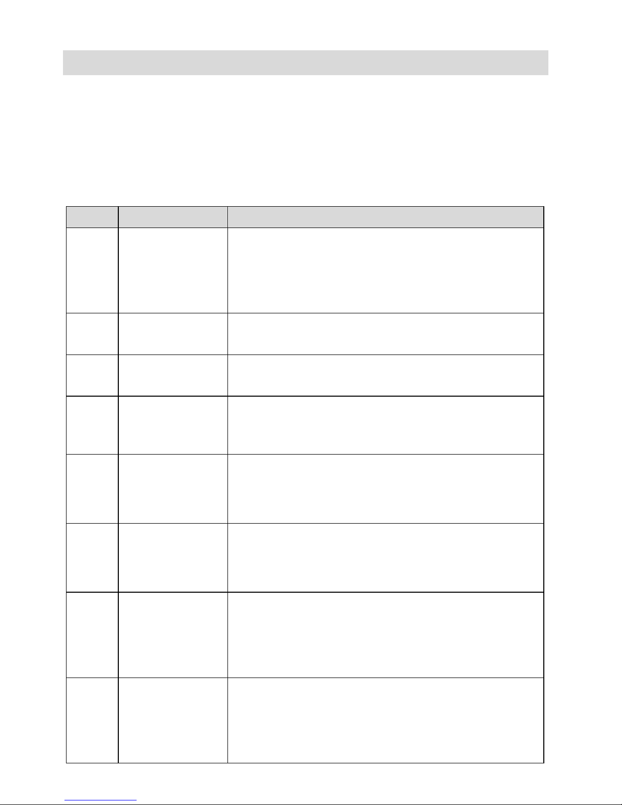
Slot(s) Code type Description
1
Master code
(controlled)
For the master user only. Used to edit all other codes,
except for engineer and alarm receiving centre codes.
Enables event log access. Default code is 1234, however,
it is recommended to change it immediately after
setting up the system.
2-19
User codes
(controlled)
For system users.
20-25
User codes
(non-controlled)
For system users.
26-27
Limited
user codes
(controlled)
For temporary system users, valid only for 24 hours.
28
Duress code
For all system users. For situations when a user is being
forced to operate the system, it simultaneously sends a
“silent” duress event message to the alarm receiving
centre or to a pre-defined user.
29 Telecontrol code
Enables the user to perform remote system
operations and also 2-way audio communication
to the control panel via GSM. Refer to the Full
Installation Manual for details.
30
Alarm Receiving
Centre / TWA
code
For alarm receiving centre operator. Used to establish
two-way audio (TWA) communication with the control
panel for up to 10 minutes after an alarm activation.
This code doesn’t grant access to any additional system
functions. See the Full Installation Manual for details.
32 Engineer code
For the engineer only. Enables access to the
Programming menu, and enables viewing and clearing
the event log. Default code is 1111, however, it is
recommended to change it immediately after installing
the system.
Page 28
28
Assigning, Editing, and Deleting Users (User Codes)
System users (user codes) are typically designated from RISCO Cloud
(see Step 10: Connecting to , page 32). Alternatively, they can be assigned
from the control panel.
NOTE: At initial system installation, it is highly recommended that the
master user and engineer edit their default codes to be ones that are unique
and confidential.
NOTE: Master and engineer codes cannot be deleted.
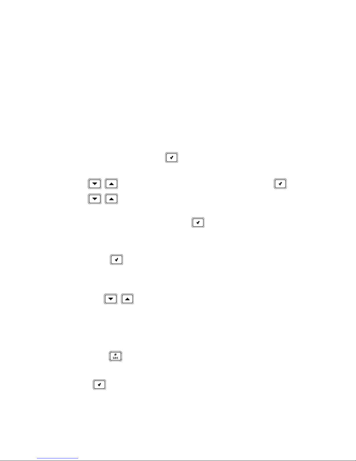
To assign, edit, and delete user codes:
1. At the control panel, press , and then enter the master code
(default is 1234) or the engineer code (default is 1111).
2. Use to scroll to 4. USER CODES, and then press .
3. Use to scroll to the specific code slot that you would like
to assign, edit or delete (see chart above for the available slots and
their descriptions), and then press .
4. Scroll and select either: 1. EDIT CODE (to change or delete a code)
or 2.DESCRIPTOR (to change the code description / name), and
then press .
5. Enter either the changed code or the changed code description as
follows:
Use to move from character to character on the display
(or wait a second after entering a character to automatically move
to the next space).
Press any button repeatedly to toggle between the letters and
number printed on it.
Press to delete a character.
NOTE: If you want to delete a code, change (edit) it to 0000.
6. Press to confirm.
Page 29
29
Designating a Follow Me Number
You can designate the cell phone number of a system user to receive SMS
Follow Me notifications of system events.
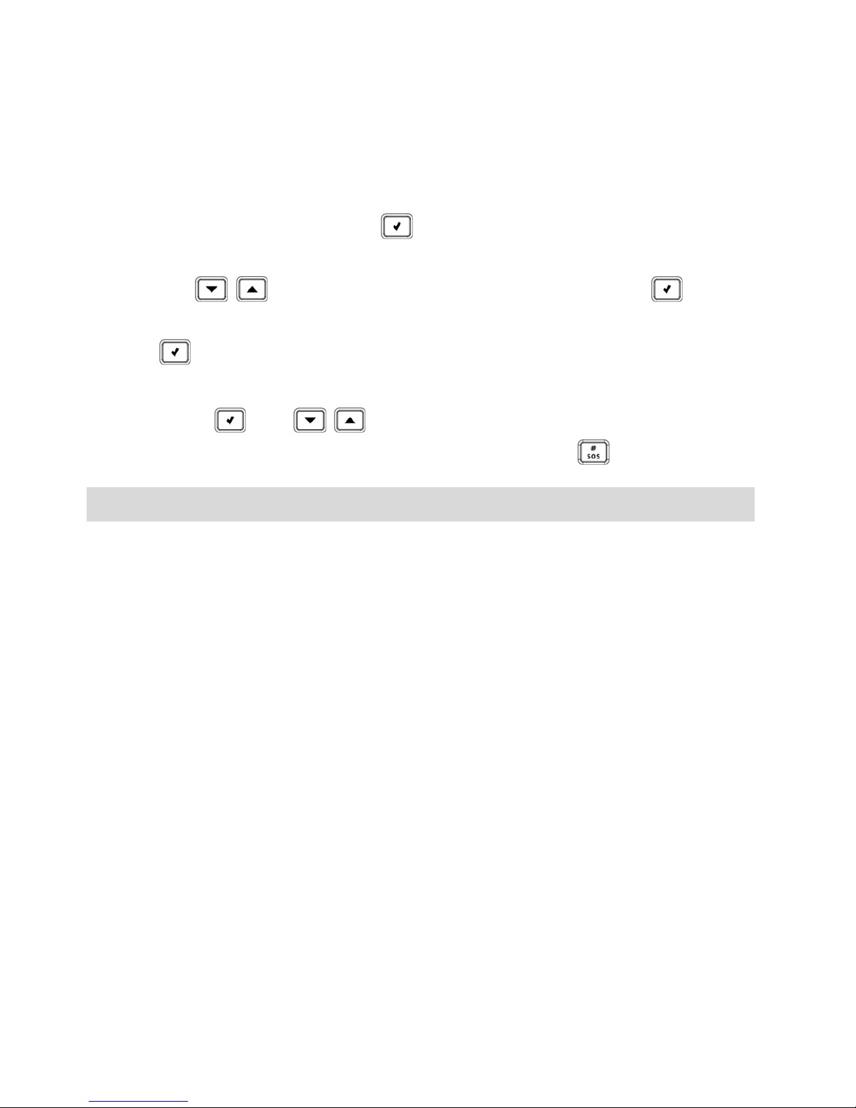
To designate a Follow Me number:
1. At the control panel, press and then enter the master code
(default is 1234) or the engineer code (default is 1111).
2.
Use to scroll to 5. FOLLOW ME #, and then press .
3.
Enter the cell phone number (including area code), and then press
.
NOTE: To edit the Follow Me number, scroll to 5. FOLLOW ME #, and
then press . Use to move from digit to digit on the display,
while you enter the changed cell phone number. Press to delete a digit.
Step 9: Establishing System Communication
Communication Channels
Connection to GPRS / GSM (the default communication channels) enables
using the Cloud—the RISCO Group Application Server (RISCO Cloud) to
handle all communication between the system and Smartphone / Web
application users. It enables remote system monitoring and control, such as
system arming / disarming, receiving e-mail, SMS, and voice notifications,
as well as viewing the event history log.
Connecting to GPRS / GSM
To connect to GPRS / GSM:
1. Make sure the SIM card is installed (see Installing the SIM Card,
page 7).
2. If your default APN (Access Point Name) is not set to INTERNET
(or if you are not sure what the APN is set to), then go into the edit
menu to view and/or edit the APN to be INTERNET. Also, if your
cellular provider has provided a user name and password, you
will need to enter that information as well (see Editing the APN,
page 30).
Page 30

30
Editing the APN
The APN connects automatically, however in certain circumstances there
may be a need to manually edit the APN definitions.
Before manually editing the APN, you need to disable Auto APN.
To disable Auto APN:
1. At the control panel keypad, press and then enter the engineer
code (default is 1111).
2. Go to: 9 > 5 > 7 > 6 > 5 and set Auto APN to Disabled.
To manually edit the APN:
1. At the control panel keypad, press and then enter the engineer
code (default is 1111).
2. Enter 9 > 5 > 7 > 6 > 1; INTERNET displays by default.
3. Either press to select the default APN name INTERNET, or if
the cellular provider has supplied a different APN name, enter that
instead:
Use to move from character to character on the
display (or wait a second after entering a character to
automatically move to the next space).
Press any button repeatedly to toggle between the letters and
number printed on it.
Press to delete a character.
4. After your entry, press ; USER NAME appears.
5. If you have not been provided with a user name and password by
the cellular provider, then press to exit the APN editing. Do
not create and enter your own user name or password.
6. If you have been provided with a user name and password by the
cellular provider, enter them both (and after each entry press );
GPRS WRITE TMO 25 appears.
7. Press to exit the APN editing.
Page 31

31
Connecting to WiFi
To connect via WiFi , you must select your router’s WiFi network.
NOTE: Your router’s WiFi must be activated in order for the control panel
to recognize and communicate with the router.
Selecting your WiFi Network:
To select your WiFi network (if not yet selected):
1. Press for 3 seconds and then enter the master code (default is
1234); SETTING WI-FI 1. SCAN WI-FI displays.
2. Press ; the control panel scans for WiFi networks.
3. Scroll to your router’s WiFi network, and then press .
4. Enter the password, and at the “SAVE?” prompt, press ; if
connection is successful there is no message. If there is a problem
in connecting, an error message displays.
Changing the WiFi Network
If, for example, you have changed your router, you must set the new WiFi
network and password.
To change a WiFi network and/or enable WiFI Setting with a
Smartphone:
1. Press for 3 seconds and then enter the master code (default is
1234); SETTING WI-FI 1. SCAN WI-FI displays.
2. [To change the WiFi network]:
a. Press ; the control panel scans for WiFi networks
b. Scroll to your router’s WiFi network, and then press .
c. Enter the password, and then at the “SAVE?” prompt, press ; if
connection is successful there is no message. If there is a problem in
connecting, an error message displays.
Page 32
32
Step 10: Connecting to RISCO Cloud
After connecting to GPRS, register first in order to log in to RISCO Cloud.
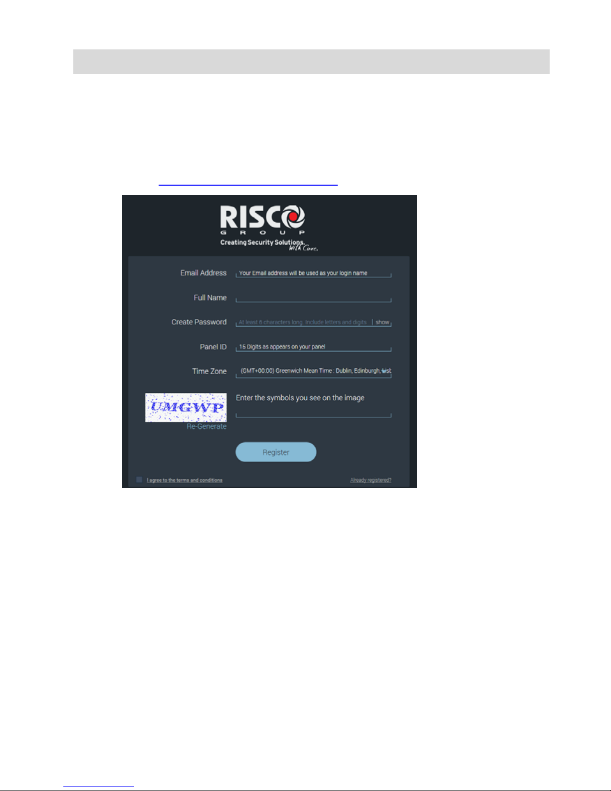
Registering to RISCO Cloud
To register to RISCO Cloud:
1. Go to www.riscocloud.com/register
2. Complete all the required fields:
Email Address: The user’s e-mail address (required for 1st
time activation – it can be changed at a later time).
Full Name: The user’s full name.
Create Password: Must be a minimum of 6 characters, and
have at least one digit.
Panel ID: The 15-digit panel ID as appears on the sticker
located on the side of the control panel.
Time Zone: Select from the dropdown list.
Code: Type the security code as it appears.
3. Select the checkbox to agree to the terms and conditions.
Page 33
33
4. Press REGISTER.
5. To complete registration, the user must open the e-mail message
received (at the e-mail address defined as the Login name), and
then click the link.
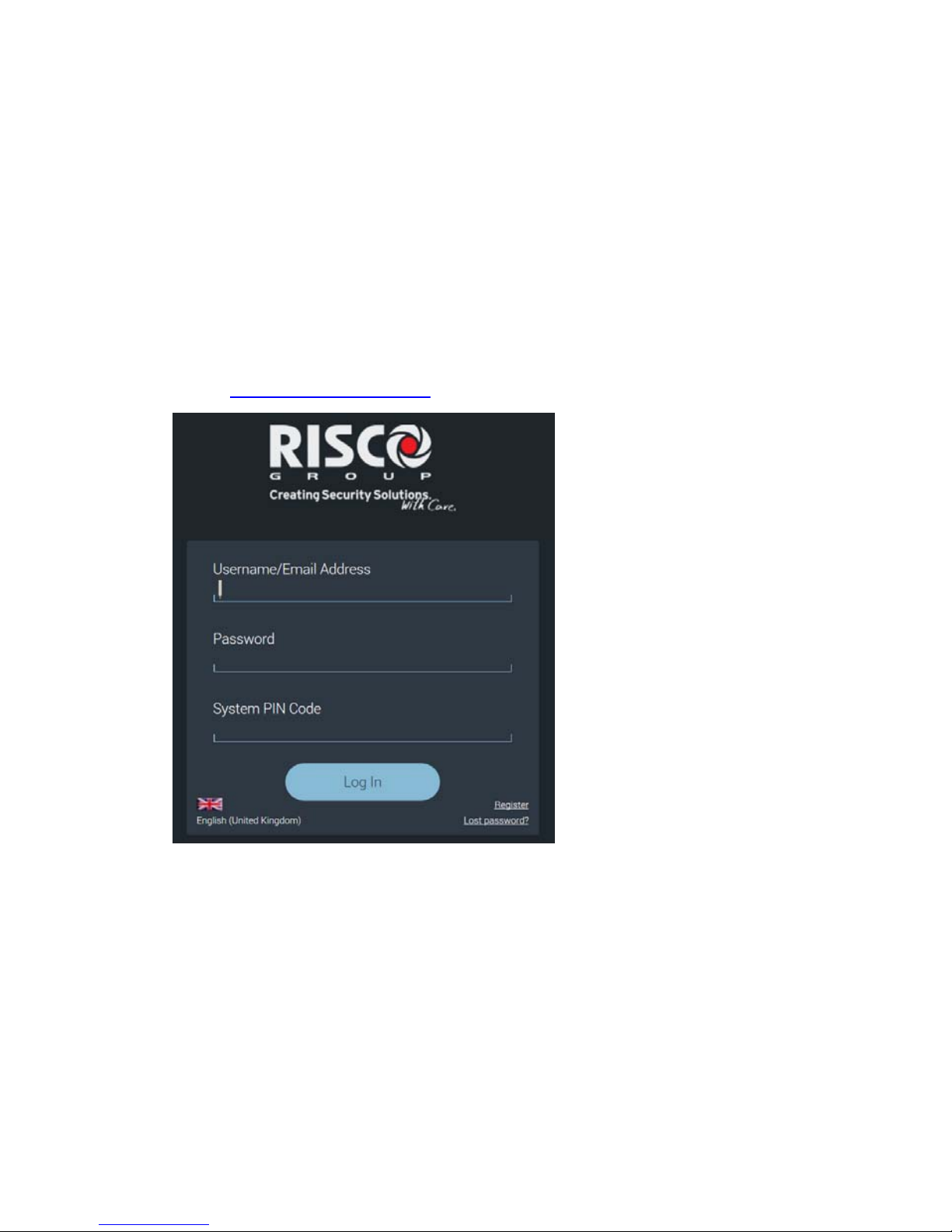
Logging in to RISCO Cloud
You can also log in to RISCO Cloud from your Smartphone
(see Using the Smartphone and Web Applications, on page 39).
To log in to RISCO Cloud:
1. Go to www.riscocloud.com
2. Enter the user name and password that you supplied during the
registration process.
3. Enter your PIN code (same as the user code) – the default master
code is 1234.
4. Press Log In.
Page 34
34
Operating the System
Before You Start Using the System
After completing all initial system setup steps, before you use the system,
first check if any trouble messages still display on the control panel (use
to scroll and view). If any remain, see Troubleshooting on page 40.
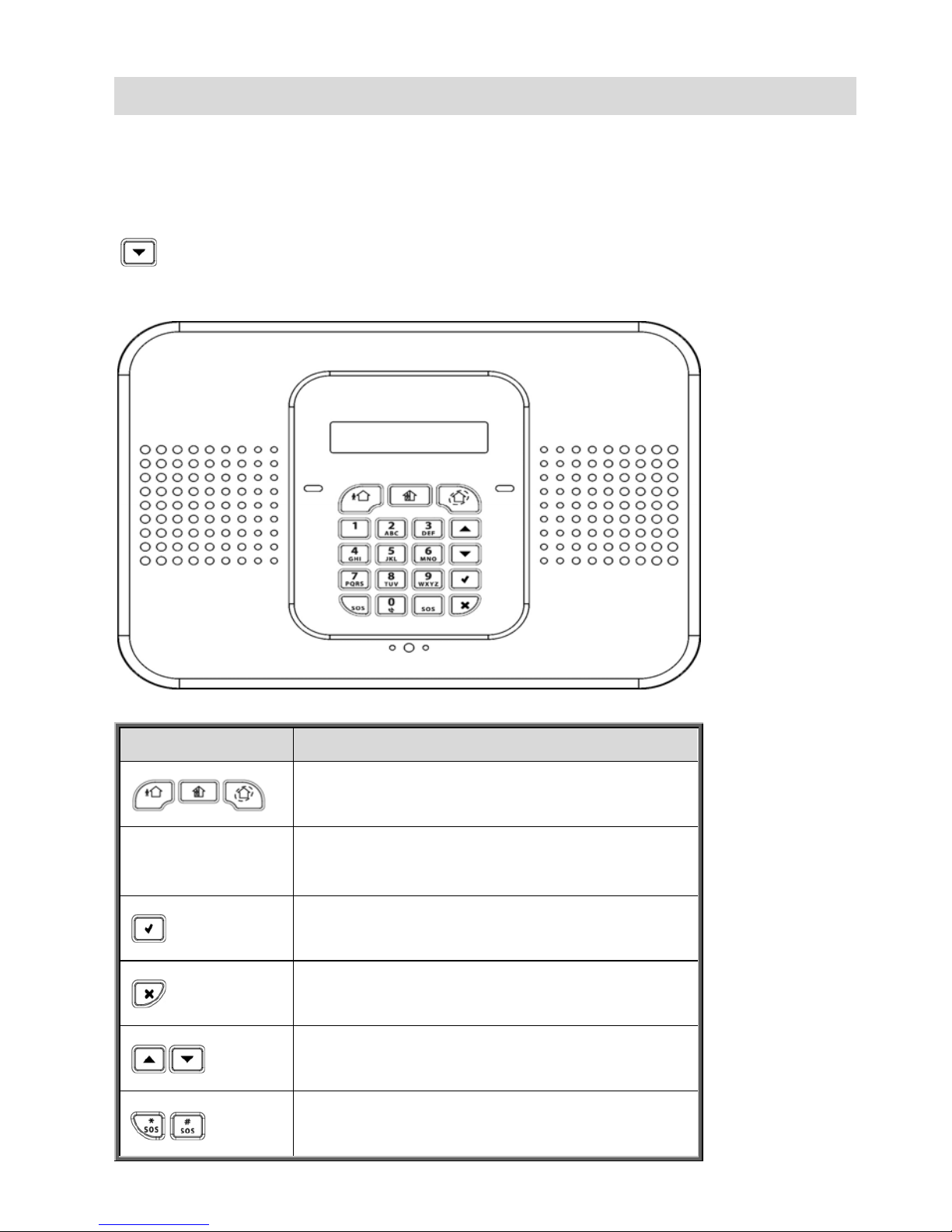
Describing the Control Panel Keypad
Keypad buttons Description
Arming – from left to right: full arm,
partial arm, perimeter arm
(buttons for
user code)
Disarming – to disarm the system. Also
cancels sounder upon alarm activation.
Accept / OK – used after selecting, for
confirming, and for saving
Reject / cancel – for cancelling current
selection, or returning to prior menu item
Menu navigation – for scrolling
up / down through menu options
Panic alarm – sends notification (control
panel, however, is silent)
Page 35
35
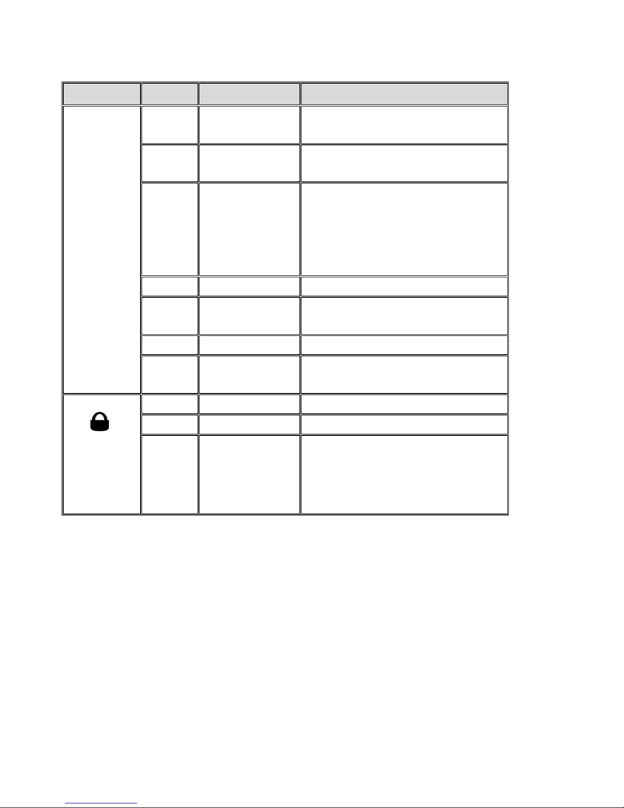
Describing the Control Panel LEDs
LED Color State Status
OK LED
N/A Off
Both AC electrical power and
battery power are disconnected
Green On
System power status is ok (no
system trouble)
Green Flashing
Open (activated) zone. Check
that the windows and doors are
closed and no movement is
detected by the detectors within
the protected area.
Yellow On System trouble
Yellow Slow flashing
Low battery (in control panel or
transmitters)
Yellow Quick flashing AC power loss
Yellow
Slow and
quick flashing
System trouble in addition to AC
power loss / low battery
(System
Status
LED)
N/A Off System is disarmed
Green On System is armed
Red Flashing
Alarm activation (flashes until
system is disarmed).
NOTE: Scroll on keypad to view
trouble message(s).
Describing the Ke yfob LED
The keyfob LED flashes when transmitting a command, and also flashes to
indicate a low battery condition
.
Describing the PIR Detector LED
The PIR LED flashes upon detection.
Page 36
36
Describing User Commands
Commands to control and use the system (such as arming and disarming)
are typically performed by system users at the control panel, keyfob, as well
as via the Smartphone and Web-browser applications.
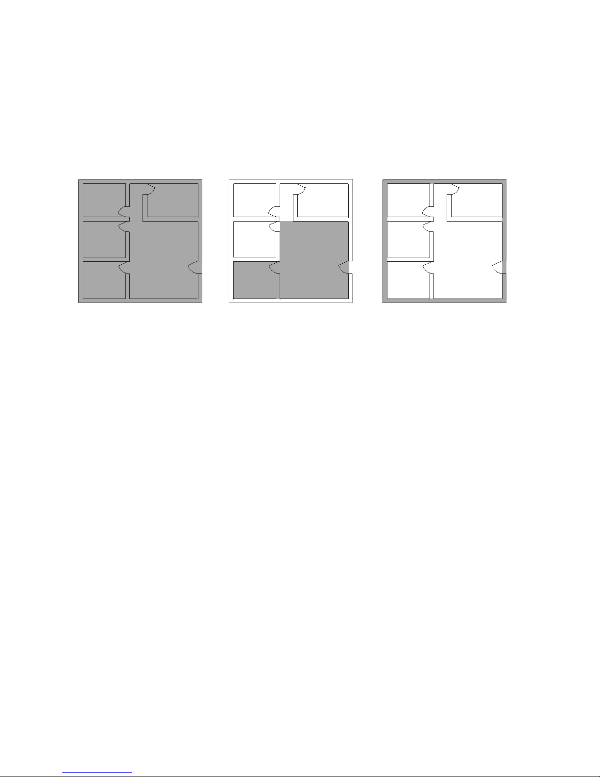
Describing Arming Modes
Full arm:
For arming premises
that are fully vacated
Partial arm:
For arming one part
(but not all) of the
premises
Perimeter arm:
For arming the
perimeter, while the
premises are
occupied
Page 37
37
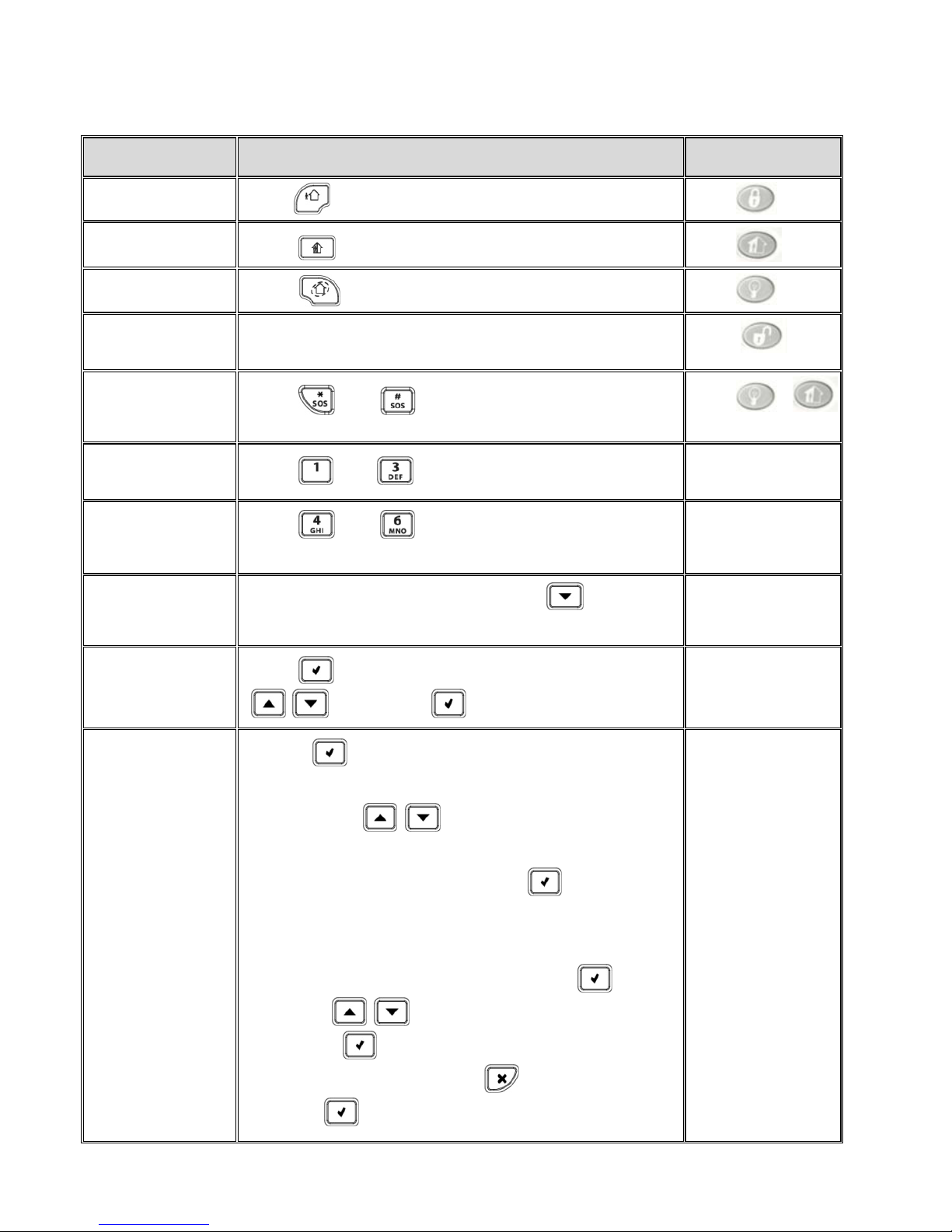
Performing Commands from Control Panel and Keyfob
Command Control Panel Procedure Keyfob Procedure
Full arm
Press . Then, if prompted, enter user code.
Press .
Partial arm
Press . Then, if prompted, enter user code.
Press .
Perimeter arm
Press . Then, if prompted, enter user code.
Press .
Disarm (and
silence alarms)
Enter user code
Press .
Activate panic
alarm
Press and simultaneously.
Press &
simultaneously.
Activate fire
alarm
Press and simultaneously.
N/A
Activate
medical alarm
Press and simultaneously; control panel
beeps to indicate alarm activation.
N/A
View system
troubles
If a trouble message displays, press to scroll
and view current system troubles.
N/A
Access menu
mode
Press and then enter user code. Scroll with
, then press to confirm selection.
N/A
Bypass /
unbypass zones
1. Press and enter master code (default is 1234).
2. Press 2.
3. Scroll with to select either:
2. Unbypass All (to unbypass all zones that
have been bypassed). Press twice.
-OR-
Bypass/Unbyp (to select a specific zone to
either bypass or unbypass). Press , then
use to scroll to the zone, and now
press to toggle between bypass/unbypass
options. Finally, press to select, followed
by to save the changes.
N/A
Page 38
38
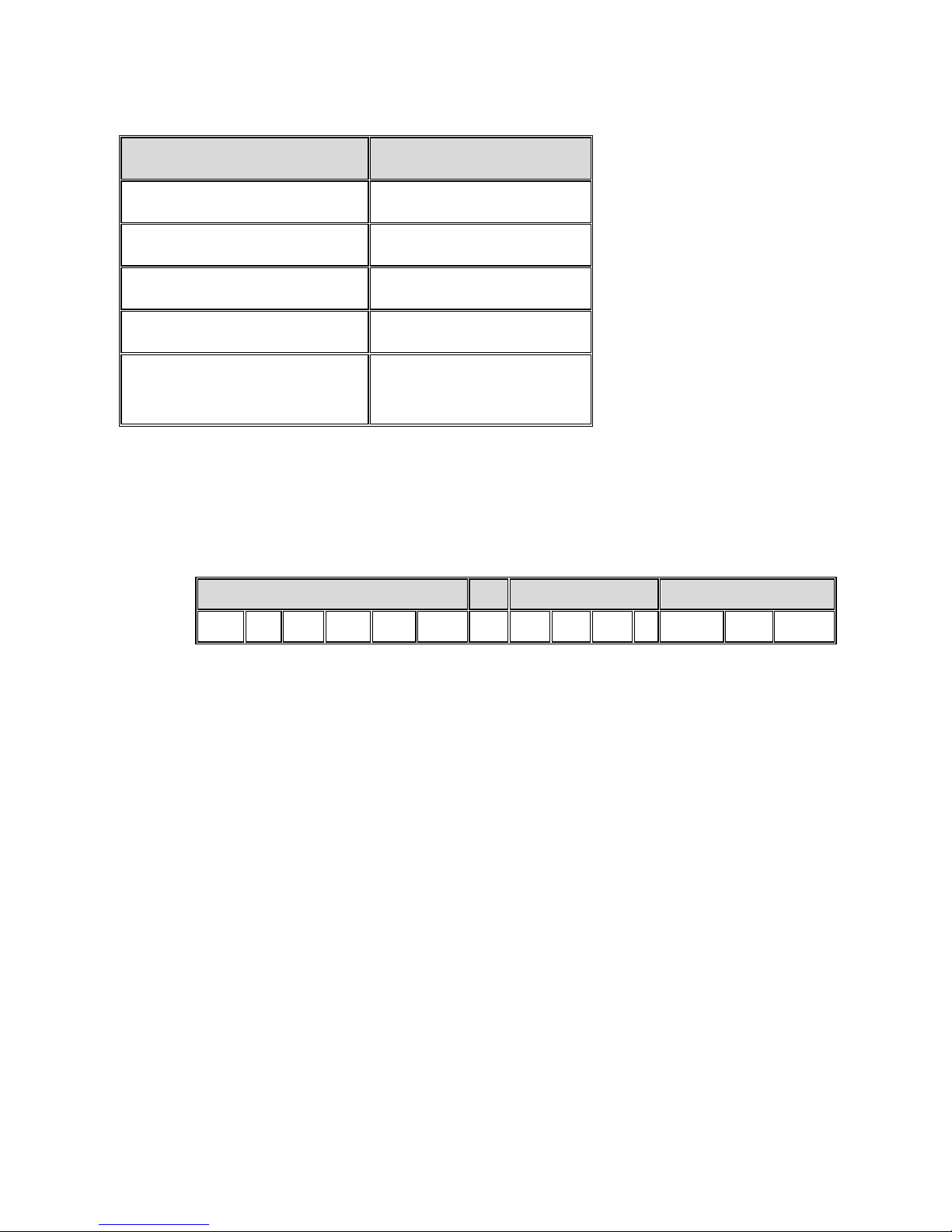
Sending SMS Commands
Command Description SMS Command Code
Disarm 120
Full arm 121
Partial arm 122
Perimeter arm 123
Receive system arming
status (master user only)
200
To send a command by SMS:
From your cellular phone, enter text (in the order as shown in this
example):
Command Description # User Code Command code
D I S A R M # 1 2 3 4 1 2 0
NOTES:
If you do not enter the command description (optional),
then start the SMS command with the # symbol
The command description can be up to 43 characters long
(either capital or lower case letters)
Do not leave any spaces between the entered text
Page 39
39
Using the Smartphone and Web Applications
Smartphone App
The Smartphone RISCO Cloud app will guide you through the operational
instructions. Download from the Apple’s App Store for iOS devices, or from
Google Play for Android devices.
iOS app Android app
Web Application
For operational instructions, refer to the RISCO Cloud Web application
documentation at: http://www.riscogroup.com/products/product/50870
Page 40
40
Troubleshooting
The following are a list of trouble messages that may appear on the control
panel display, along with actions the user can perform for resolution.
Trouble Message Description Corrective Action
TAMPER ALARM
Component has been
removed (or moved)
from the mounting
location, or component
cover has been opened.
Return component to its install
location (mounted in the correct
position)
Close component cover
AC LOSS
No electrical AC power
supply to control panel.
Check the power cable / circuit
breaker.
BATTERY LOW
CONTROL PANEL
The control panel battery
needs recharging.
Connect the control panel to the
electrical power supply.
BATTERY MISSING
Control panel battery is
not connected or is
missing.
For engineer only: First make sure
that the electrical power supply is
disconnected from the control
panel, and then open the panel and
reconnect / install the battery.
LOW BATTERY
ZONE#
The battery of the
specified detector /
accessory is low.
Per the zone that displays, replace
the battery in the respective
detector / accessory (see
System Maintenance — Battery
Replacement
, page 43).
LOW BATTERY
KEYFOB#
The battery of the
specified keyfob is low.
According to the keyfob number
that displays, replace the battery in
the respective keyfob (see
Replacing Keyfob Batteries, page 43).
MEDIA LOSS GPRS
Either the APN has the
wrong settings, the SIM
card is not enabled for
GPRS, or there is a loss of
GPRS signal reception.
Check the APN settings (see
Editing the APN, page 30)
Check if the SIM card is GPRS-
enabled (insert the SIM card in
your cell phone to see if Internet
is available)
Relocate the control panel to a
place with better reception
Page 41
41
Trouble Message Description Corrective Action
MEDIA LOSS GSM
The cellular network is
down, reception is not
adequate, or the SIM card
has a depleted usage
allowance.
The cellular network needs to be
restored, the control panel needs to
be relocated to a place with better
reception, or the SIM card usage
allowance needs to be topped up.
MEDIA LOSS WIFI
The router line is down /
not connected, or too far
from the control panel.
Ensure router connectivity. Move
the router and control panel closed
to each other.
DEVICE TROUBLE
WIFI MODULE
Faulty Wi-Fi module host
CPU connection.
Contact your engineer / provider
or customer support.
DEVICE TROUBLE
GSM
Faulty GSM/GPRS
module
Contact your engineer / provider
or customer support.
ELAS LOGIN FAIL
The control panel ID and
password are not
recognized by RISCO
Cloud
Contact your engineer / provider
or customer support.
XML FAIL
Problem with Cloud
communication.
Contact your engineer / provider
or refer to the Full Installation
Manual.
SIM CARD ERROR
The SIM card is not
recognized by the control
panel.
Check if the SIM card is installed
correctly (see Installing the SIM
Card, page 7).
PIN CODE ERROR
The SIM card PIN code is
not recognized by the
control panel.
Refer to the Full Installation
Manual.
NO REGISTERED
SENSORS
All detector registrations
were deleted.
Manually register all your
detectors again (see Registering
Additional Components, page 16).
TIME NOT SET
The local time of the
control panel is not
configured.
The control panel's time is
automatically set from the Cloud
server, so wait until Cloud
connectivity is established.
Page 42

42
Trouble Message Description Corrective Action
ALL ZONES
BYPASSED
All zones have been
bypassed (the system
cannot be armed in this
condition).
In order to arm the system,
unbypass one or more of the
zones.
Page 43
43
System Maintenance — Battery Replacement
The user can replace batteries for keyfobs, detectors and other accessories.
Check the RISCO Group website for battery updates.
WARNING: Ensure a battery is replaced with the correct type and
polarity. Do not recharge, disassemble, deform, expose
to high heat, or incinerate batteries. Failure to observe
these warnings may result in explosion, fire, damage,
injury, or death.
CAUTION: Do not attempt to replace the battery in the control
panel yourself – always contact an engineer / provider.
CAUTION: Always dispose of used batteries according to applicable
law and regulations.
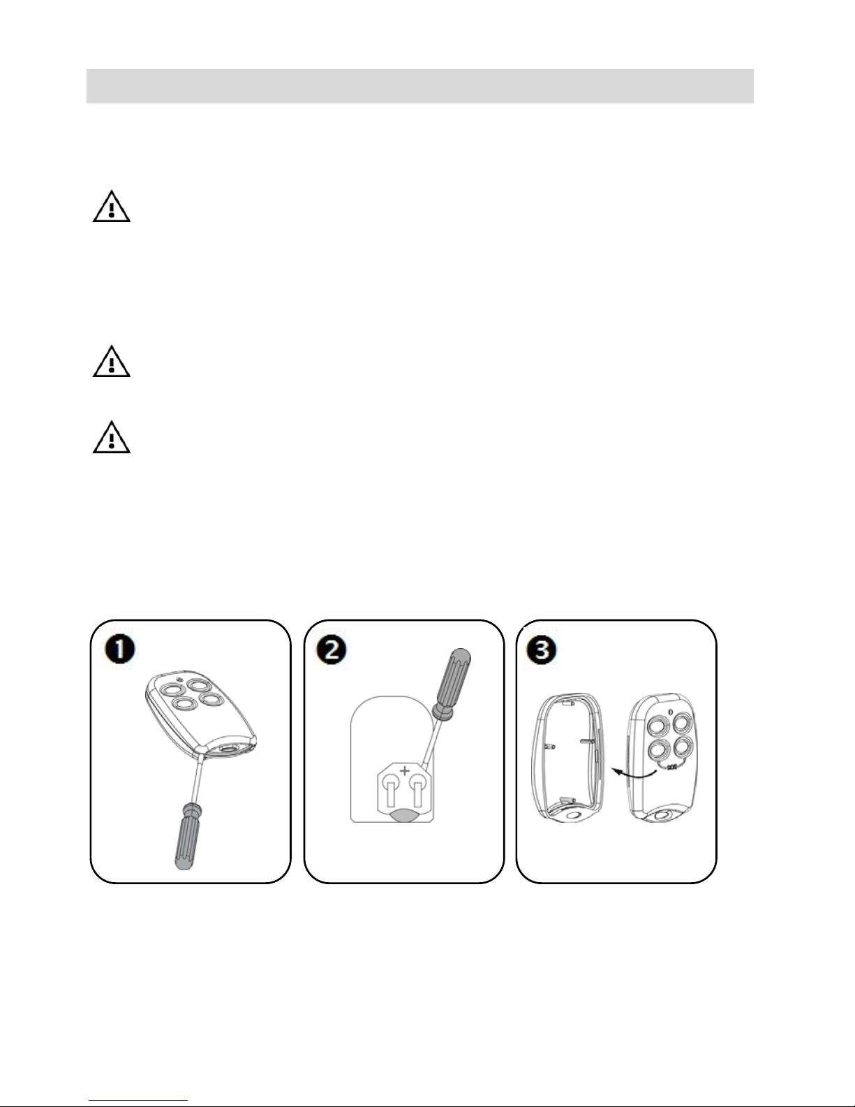
Replacing Keyfob Batteries
To replace keyfob batteries:
Page 44

44
Replacing Component Batteries
When replacing batteries in detectors and other system accessories, do the
following to prevent activating the sounder:
To replace component batteries:
1. From the control panel, press for about 3 seconds until
REPLACE BATTERY displays.
2. Remove the dead battery, and then insert the new battery; the
tamper alarm is activated as usual, but the sounder does not
sound.
3. Press to exit the battery replacement mode.
Page 45
45
Product Specification
General
Wireless zones (wireless RF technology) 32
Hard-wired zone 1
Wireless keyfobs 19
Wireless repeaters (range extenders) 4
2-way wireless sounder 1
User codes 31
Arming methods full, partial, or perimeter
Event log capacity (time & date stamped) 1022
Event reporting
GPRS with GSM and WiFi
(voice or SMS SIA/CID)
Communication channels GPRS, GSM, WiFi
Data encryption
66-bit encryption with SecuriCode™
technology (hopping and rolling code)
Control Panel
Power input 230 VAC, 50 Hz, 4 VA
Battery low below 7.15 V
Backup battery pack
4.8 V 1.3 Ah (4 x 1.2 NiMH), size AA,
rechargeable
Built-in sounder 93 dB @ 10 ft
Tamper switch N.C. (normally closed) by default
Fuse ratings 63 mA / 250 V for 230 VAC
Maximum auxiliary output current rating 50 mA
PGM relay output contact rating 100 mA (max. load)
Operating temperature -10 –55° C (14–131° F)
Weight 1.350 g (3 lbs)
Dimensions 210 x 153 x 40 mm (8.3 x 6 x 1.6 in)
Frequency 868 or 433 MHz (country-dependant)
Page 46
46
PIR PI (Model EL-2645PI)
Power 3.6 V lithium battery, size ½ AA
Current consumption 30 mA (transmission), 8 µA standby
Pyroelectric sensor Dual element
Maximum coverage 11 x 11 m (36.1 x 36.1 ft)
Adaptive temperature compensation
RFI immunity: according to EN 50130-4
Operating temperature -10 –55° C (14–131° F)
Fire protection ABS plastic housing
Dimensions 110 x 60 x 45 mm
Frequency 868 or 433 MHz (country-dependant)
Magnetic Door / Window Contact Detector (Model EL-2601)
Power 3.6 V lithium battery, size ½ AA
Current consumption 25 mA (transmission), 10A (standby)
Antenna Built-in internal whip
Loop input voltage range 0–15 VDC / AC (peak to peak)
RFI immunity 10 V/m
Operating temperature -10 –55° C (14–131° F)
Dimensions
67 x 30 x 26 mm (transmitter)
50 x 13 x 10 mm (magnet)
Frequency 868 or 433 MHz (country-dependant)
Keyfob (Model EL-2614E)
Power 3 V lithium battery, size CR2032
Current consumption 20 mA (transmission), 2 A (standby)
Antenna Built-in whip
RFI immunity 10 V/m
Operating temperature -10 –55° C (14–131° F)
Dimensions 62 x 42 x 15 mm
Frequency 868 or 433 MHz (country-dependent)
Page 47

47
Certification and Standards
RTTE Compliance Statement
Hereby, RISCO Group declares that this product is in compliance with the
essential requirements and other relevant provisions of Directive 1999/5/EC.
For the CE Declaration of Conformity please refer to our website:
www.riscogroup.com
Page 48

48
RISCO Group Limited Warranty
RISCO Ltd., its subsidiaries and affiliates (“RISCO") guarantee RISCO’s hardware
products to be free from defects in materials and workmanship when used and stored
under normal conditions and in accordance with the instructions for use supplied by
RISCO, for a period of (i) 24 months from the date of connection to the RISCO Cloud (for
cloud connected products) or (ii) 24 months from production (for other products which
are non-cloud connected), as the case may be (each, the “Product Warranty Period”
respectively).
Contact with customers only. This Product Warranty is solely for the benefit of the
customer who purchased the product directly from RISCO, or from any authorized
distributor of RISCO. Nothing in this Warranty obligates RISCO to accept product
returns directly from end users that purchased the products for their own use from
RISCO’s customer or from any installer of RISCO, or otherwise provide warranty or
other services to any such end user. RISCO customer shall handle all interactions with its
end users in connection with the Warranty, inter alia regarding the Warranty. RISCO’s
customer shall make no warranties, representations, guarantees or statements to its
customers or other third parties that suggest that RISCO has any warranty or service
obligation to, or any contractual privy with, any recipient of a product.
Return Material Authorization. In the event that a material defect in a product shall be
discovered and reported during the Product Warranty Period, RISCO shall, at its option,
and at customer's expense, either: (i) accept return of the defective Product and repair or
have repaired the defective Product, or (ii) accept return of the defective Product and
provide a replacement product to the customer. The customer must obtain a Return
Material Authorization (“RMA”) number from RISCO prior to returning any Product to
RISCO. The returned product must be accompanied with a detailed description of the
defect discovered (“Defect Description”) and must otherwise follow RISCO’s thencurrent RMA procedure in connection with any such return. If RISCO determines in its
reasonable discretion that any Product returned by customer conforms to the applicable
warranty (“Non-Defective Products”), RISCO will notify the customer of such
determination and will return the applicable Product to customer at customer’s expense.
In addition, RISCO may propose and assess customer a charge for testing and
examination of Non-Defective Products.
Entire Liability. The repair or replacement of products in accordance with this warranty
shall be RISCO’s entire liability and customer’s sole and exclusive remedy in case a
material defect in a product shall be discovered and reported as required herein.
RISCO’s obligation and the Warranty are contingent upon the full payment by customer
for such Product and upon a proven weekly testing and examination of the product
functionality.
Page 49

49
Limitations. The Product Warranty is the only warranty made by RISCO with respect to
the Products. The warranty is not transferable to any third party. To the maximum extent
permitted by applicable law, the Product Warranty does not apply and will be void if: (i)
the conditions set forth above are not met (including, but not limited to, full payment by
customer for the product and a proven weekly testing and examination of the product
functionality); (ii) if the Products or any part or component thereof: (a) have been subjected
to improper operation or installation; (b) have been subject to neglect, abuse, willful
damage, abnormal working conditions, failure to follow RISCO’s instructions (whether
oral or in writing); (c) have been misused, altered, modified or repaired without RISCO’s
written approval or combined with, or installed on products, or equipment of the customer
or of any third party; (d) have been damaged by any factor beyond RISCO’s reasonable
control such as, but not limited to, power failure, electric power surges, or unsuitable third
party components and the interaction of software therewith or (e) any delay or other
failure in performance of the product attributable to any means of communications,
provided by any third party service provider (including, but not limited to) GSM
interruptions, lack of or internet outage and/or telephony failure.
BATTERIES ARE EXPLICITLY EXCLUDED FROM THE WARRANTY AND RISCO
SHALL NOT BE HELD RESPONSIBLE OR LIABLE IN RELATION THERETO, AND
THE ONLY WARRANTY APPLICABLE THERETO, IF ANY, IS THE BATTERY
MANUFACTURER'S WARRANTY.
RISCO makes no other warranty, expressed or implied, and makes no warranty of
merchantability or of fitness for any particular purpose. For the sake of good order and
avoidance of any doubt:
DISCLAIMER. EXCEPT FOR THE WARRANTIES SET FORTH HEREIN, RISCO AND ITS
LICENSORS HEREBY DISCLAIM ALL EXPRESS, IMPLIED OR STATUTORY,
REPRESENTATIONS, WARRANTIES, GUARANTEES, AND CONDITIONS WITH
REGARD TO THE PRODUCTS, INCLUDING BUT NOT LIMITED TO ANY
REPRESENTATIONS, WARRANTIES, GUARANTEES, AND CONDITIONS OF
MERCHANTABILITY, FITNESS FOR A PARTICULAR PURPOSE, TITLE AND LOSS OF
DATA. WITHOUT LIMITING THE GENERALITY OF THE FOREGOING, RISCO AND
ITS LICENSORS DO NOT REPRESENT OR WARRANT THAT: (I) THE OPERATION OR
USE OF THE PRODUCT WILL BE TIMELY, SECURE, UNINTERRUPTED OR ERRORFREE; (ii) THAT ANY FILES, CONTENT OR INFORMATION OF ANY KIND THAT
MAY BE ACCESSED THROUGH THE PRODUCT BY CUSTOMER OR END USER
SHALL REMAIN SECURED OR NON DAMAGED. CUSTOMER ACKNOWLEDGES
THAT NEITHER RISCO NOR ITS LICENSORS CONTROL THE TRANSFER OF DATA
OVER COMMUNICATIONS FACILITIES, INCLUDING THE INTERNET, GSM OR
OTHER MEANS OF COMMUNICATIONS AND THAT RISCO’S PRODUCTS, MAY BE
SUBJECT TO LIMITATIONS, DELAYS, AND OTHER PROBLEMS INHERENT IN THE
USE OF SUCH MEANS OF COMMUNICATIONS. RISCO IS NOT RESPONSIBLE FOR
ANY DELAYS, DELIVERY FAILURES, OR OTHER DAMAGE RESULTING FROM SUCH
PROBLEMS.
Page 50

50
RISCO WARRANTS THAT ITS PRODUCTS DO NOT, TO THE BEST OF ITS
KNOWLEDGE, INFRINGE UPON ANY PATENT, COPYRIGHT, TRADEMARK,
TRADE SECRET OR OTHER INTELLECTUAL PROPERTY RIGHT
IN ANY EVENT RISCO SHALL NOT BE LIABLE FOR ANY AMOUNTS
REPRESENTING LOST REVENUES OR PROFITS, PUNITIVE DAMAGES, OR FOR
ANY OTHER INDIRECT, SPECIAL, INCIDENTAL, OR CONSEQUENTIAL
DAMAGES, EVEN IF THEY WERE FORESEEABLE OR RISCO HAS BEEN INFORMED
OF THEIR POTENTIAL.
RISCO does not install or integrate the product in the end user security system and is
therefore not responsible for and cannot guarantee the performance of the end user
security system which uses the product.
RISCO does not guarantee that the product will prevent any personal injury or property
loss by burglary, robbery, fire or otherwise; or that the product will in all cases provide
adequate warning or protection.
Customer understands that a correctly installed and maintained alarm may only reduce
the risk of burglary, robbery or fire without warning, but is not an assurance or a
guarantee that such an event will not occur or that there will be no personal injury or
property loss as a result thereof. Consequently RISCO shall have no liability for any
personal injury, property damage or loss based on a claim that the product fails to give
warning.
No employee or representative of RISCO is authorized to change this warranty in any
way or grant any other warranty.
Page 51

51
Contacting your Engineer
When in need of service, ordering components, or for questions related to
the system, please retain this information for future use when contacting
your engineer:
Engineer name:
_________________________________________
Engineer address,
telephone, e-mail:
_________________________________________
Hours of business:
_________________________________________
Website:
_________________________________________
Other information:
_________________________________________
Page 52
52
Contacting RISCO Group
International Headquarters:
RISCO Group
14 Hachoma St., 75655
Rishon Le Zion, Israel
Tel: (+972-3) 963-7777
Fax: (+972-3) 961-6584
Please visit us at: www.riscogroup.com
Copyright 2016, RISCO Group All rights reserved.
09/2016
5IN2406 B
 Loading...