

Page 1

InSight
Visual Verification Platform
Cube Indoor IP Camera
Installation Guide
Page 2

Safety Precautions
These instructions are intended to ensure that the user can use the product correctly to
avoid danger or property loss.
WARNINGS:
Installation or usage of this product that is not in accordance with the intended
use as defined by the supplier and as described in the instructional materials can
result in damage, injury, or death.
Make sure this product is not accessible by children and those for whom
operation of the system is not intended.
All installation and operation should conform to your local electrical safety codes.
The power shall conform to the requirement in the SELV (Safety Extra Low
Voltage) and the Limited power source is rated 12V DC in the IEC60950-1.
If the device is permanently connected to an electrical power supply, then the
connection should include an easily-accessible disconnection device, such as a
circuit breaker. Do not connect the two power supplying sources to the device at
the same time; it may result in device damage!
Do not ever attempt to repair your device by yourself, as doing so could result in
damage, injury or death – always contact your installer / supplier agent for
service.
CAUTIONS:
Make sure the power supply voltage is correct before using the camera.
Do not drop the camera or subject it to physical shock.
Do not touch sensor modules with fingers. If cleaning is necessary, use a clean
cloth with a bit of ethanol and wipe it gently.
Do not aim the camera lens at the strong light such as sun or incandescent lamp.
The strong light can cause fatal damage to the camera.
The sensor may be burned out by a laser beam, so when any laser equipment is
being used, make sure that the surface of the sensor not be exposed to the laser
beam.
Do not place the camera in extremely hot, cold temperatures (the operating
temperature should be between -10°C ~ +50°C).
To avoid heat accumulation, good ventilation is required for a proper operating
environment.
Keep the camera away from water and any liquid.
While shipping, the camera should be packed in its original packing.
NOTE: We assume no liability or responsibility for all the fires or electrical shock caused
by improper handling or installation. We are not liable for any problems caused by
unauthorized modification or attempted repair.
Page 3

1
Contents
Safety Precautions ......................................................................................................... 2
Introduction ..................................................................................................................... 2
Features ...................................................................................................................... 2
Components and Accessories .................................................................................... 2
IP Camera Components and Dimensions..................................................................... 3
IP Camera Installation .................................................................................................... 5
Mounting the IP Camera ............................................................................................. 5
Powering-up the IP Camera ........................................................................................ 6
Connecting the IP Camera to the Network .................................................................. 6
Connecting to a LAN Network ................................................................................. 6
Connecting to a Wireless Network using WPS ........................................................ 7
Connecting to a Wireless Network using MyELAS .................................................. 7
IP Cameras and the MyELAS Web Application ............................................................ 8
Defining IP Camera Settings ....................................................................................... 8
Defining Camera Event Settings ............................................................................... 12
Product Specification ................................................................................................... 14
Performance ............................................................................................................. 14
Electronics Line 3000 Ltd. Limited Warranty ............................................................. 16
Contacting your Installer / Supplier-Agent ................................................................. 17
Contacting Electronics Line 3000 Ltd. ........................................................................ 18
Page 4

2
Introduction
Electronics Line presents InSight, a revolutionary live video verification solution
which seamlessly integrates IP Cameras within Electronic Line’s professional
security systems.
Powered by MyELAS (Electronics Line Application Server), InSight provides an
unprecedented level of security and live video monitoring capabilities to
monitoring stations and end-users alike.
The Cube Indoor IP Camera is an important part of this solution and
is easily
controlled through Electronics Line’s intuitive Web and Smartphone
applications.
Features
• Simple Plug & Play installation
• 1.3” Megapixel
• Color HD
• Day/Night
• White LED’s Length 10m
Components and Accessories
Indoor IP camera and
mounting bracket:
Electrical power adapter and
installation accessories bag:
Installation guide:
Page 5

3
IP Camera Components and Dimensions
Figure 1 IP Camera Components
Label Port Name Indicator Connector Description
1 Power
indicator
light
POWER / When camera boots up – Green
light turns on.
When camera is upgrading – Green
light flashes.
Interval is 0.5s.
When camera is in alarm – Green
light flashes.
Interval is 0.2s.
2 Network
indicator
light
NET / Wired network connection - Red
light is on.
Wireless network connection -
Green light is on.
3 Speaker / / Output audio signal (This function is
optional).
4 White light / / Can activate motion detect, PIR human
body movement detect, external alarm.
5 N/A N/A N/A N/A
Page 6

4
Label Port Name Indicator Connector Description
6 Microphone / / Directly receive audio signal (This
function is optional).
7 Micro SD
card
Micro
SD
Micro SD
card slot
SD card storage (This function is
optional).
8 Reset
button
Reset / Restore factory default setup. When
system is running normally, press the
RESET button for at least 5 seconds,
system can restore factory default setup.
9 WPS button WPS Fast
wireless
connection
Press the WPS button of the router and
the device respectively for at least 2
seconds. Usually the device connects to
the router within 1 minute.
Please note that this is for wireless router
with WPS functionality only.
10 N/A N/A N/A N/A
11 Power port DC12V / Input DC 12V power.
12 Network
port
LAN Ethernet
port
Connects to standard Ethernet
cable.
Supports PoE functionality.
Figure 2 IP Camera Dimensions
Page 7
5
IP Camera Installation
After reading the installation instructions and before installing your IP camera,
prepare a plan for mounting the IP camera at your protected site. Correct
placement of your IP camera is crucial for optimal security-monitoring
performance. First, determine which areas need to be protected and then map
out the most optimal areas for installing your IP camera.
IMPORTANT!
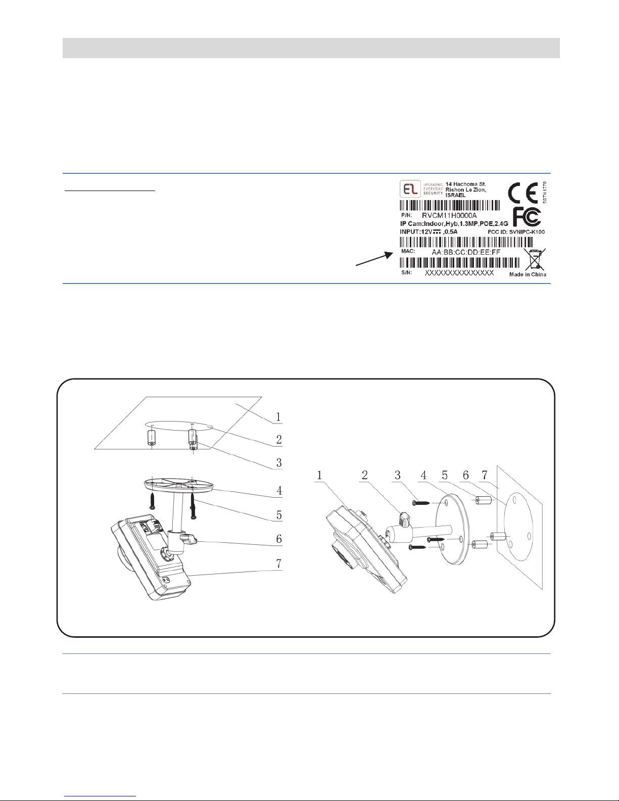
– Please make a record of the MAC
address located on the box or on the back cover of
the IP camera before installation. You may need it
during the network connection stage.
Mounting the IP Camera
The IP camera support two mounting options; ceiling and wall mount (see Figure
3 and Figure 4, below).
Figure 3 Ceiling Mount
Figure 4 Wall Mount
IMPORTANT- Please make sure the installation surface can support at least 3
times the weight of the camera and the bracket.
MAC address
Page 8
6
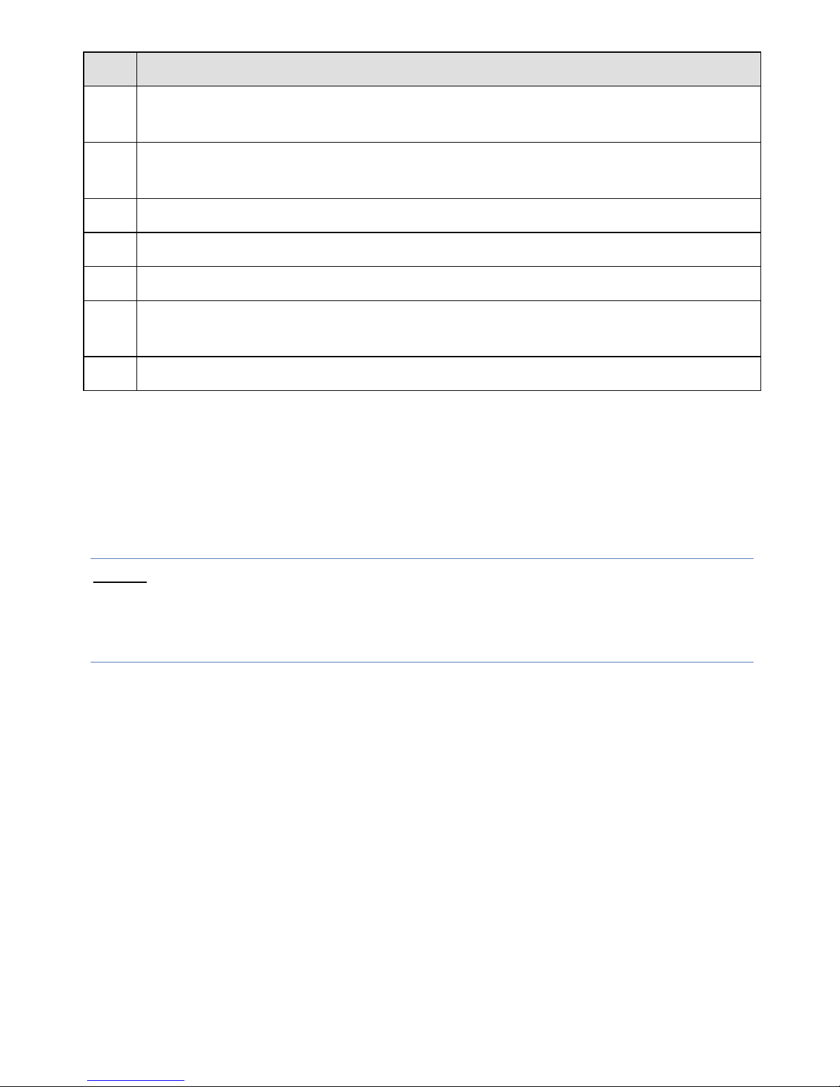
Step Description
1 Place the installation positioning template on the installation surface such as
ceiling or wall.
2 Make holes in the installation surface according to the installation positioning
template.
3 Insert the expansion bolts from the accessories bag into the holes you just made.
4 Position the IP camera base over the holes
5 Use the screws from the accessories bag to secure the IP camera firmly.
6 Loosen the adjust knob and adjust the IP camera to the correct surveillance
position according to your actual requirements.
7 Secure the adjust knob to fix the IP camera.
Powering-up the IP Camera
1. Connect the provided electrical power adapter to the Power port on the IP
camera.
2. Connect the power adapter to an electrical outlet. When the IP camera boots
up, the GREEN power indicator light turns on.
NOTE
– The IP camera can also be powered through PoE (Power over Ethernet),
which simplifies the installation (for LAN network connection only). If your
network connection is PoE compatible, you only need to connect the network
cable and not the power cable (Refer to Connecting to a LAN Network).
Connecting the IP Camera to the Network
The IP camera supports several network connection options including LAN and
Wireless connections.
Connecting to a LAN Network
Connecting the IP camera to a network using the LAN (Local Area Network)
enables easy connection and setup with compatible APs (Access Points), e.g.
gateway or router.
Page 9

7
1. Connect the incoming network cable to the Network port on the IP camera.
2. Wait just a few minutes while the IP camera automatically connects to
MyELAS. The RED network indicator light indicates that your IP camera is
now ready for defining camera settings (Refer to Defining IP Camera
Settings).
Connecting to a Wireless Network using WPS
Connecting the IP camera to a wireless network using WPS (Wi-Fi Protected
Setup) requires that the AP and Operating System supports WPS functionality.
NOTE
– Some APs have a virtual button on their management software. (Refer
to the AP’s documentation for details about using its WPS functions).
1. Once the power cord is connected, wait for 1 minute for the camera to boot
up.
2. Press and hold down the WPS button on the IP camera and the WPS button
on the AP respectively for 2 seconds. The GREEN network indicator light
indicates that your IP camera is now ready for defining camera settings
(Refer to Defining IP Camera Settings).
Connecting to a Wireless Network using MyELAS
Connecting the IP camera to a wireless network using MyELAS, requires that
you first physically connect the IP camera to the AP and then, from the MyELAS
Web Application, define the IP camera settings and establish a wireless
connection. Once a wireless connection has been established the IP camera can
then be disconnected from the AP and installed.
1. Connect the incoming network cable to the Network port on the IP camera.
2. Wait just a few minutes while the IP camera automatically connects to
MyELAS. The RED network indicator light indicates that your IP camera is
now ready
for defining camera settings.
3. Define the IP camera settings (Refer to Defining IP Camera Settings).
4. Once a wireless connection has been established, disconnect the IP camera
from the AP and install it anywhere within the monitored area.
Page 10
8
IP Cameras and the MyELAS Web Application
The MyELAS Web Application provides an interface to your control panel from a
local or remote PC via the Web. This enables you to add IP cameras to your
system and define camera and event alarm trigger settings.
IMPORTANT
– A control panel must be registered in MyELAS in order to
accept IP cameras and define camera settings (Refer to the MyELAS Web
Application User Guide or www.myelas.com/register)
Defining IP Camera Settings
Once you have connected the IP camera to the network (refer to, Connecting the
IP Camera to the Network) you can define the camera settings.
To define IP camera settings:
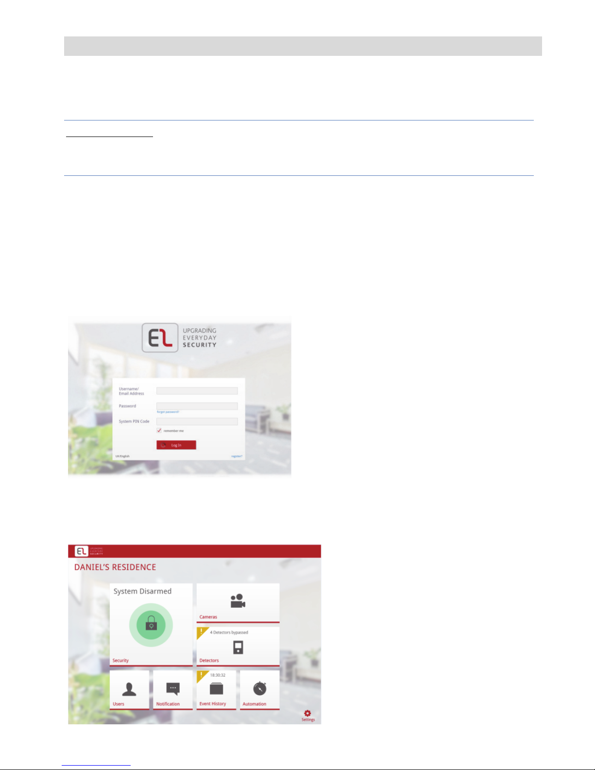
1. Enter the Web page address supplied by your service provider and press Go.
The Login page is displayed.
Figure 5 Login page
2. Enter your User Name (Email Address), Password, System PIN Code (User
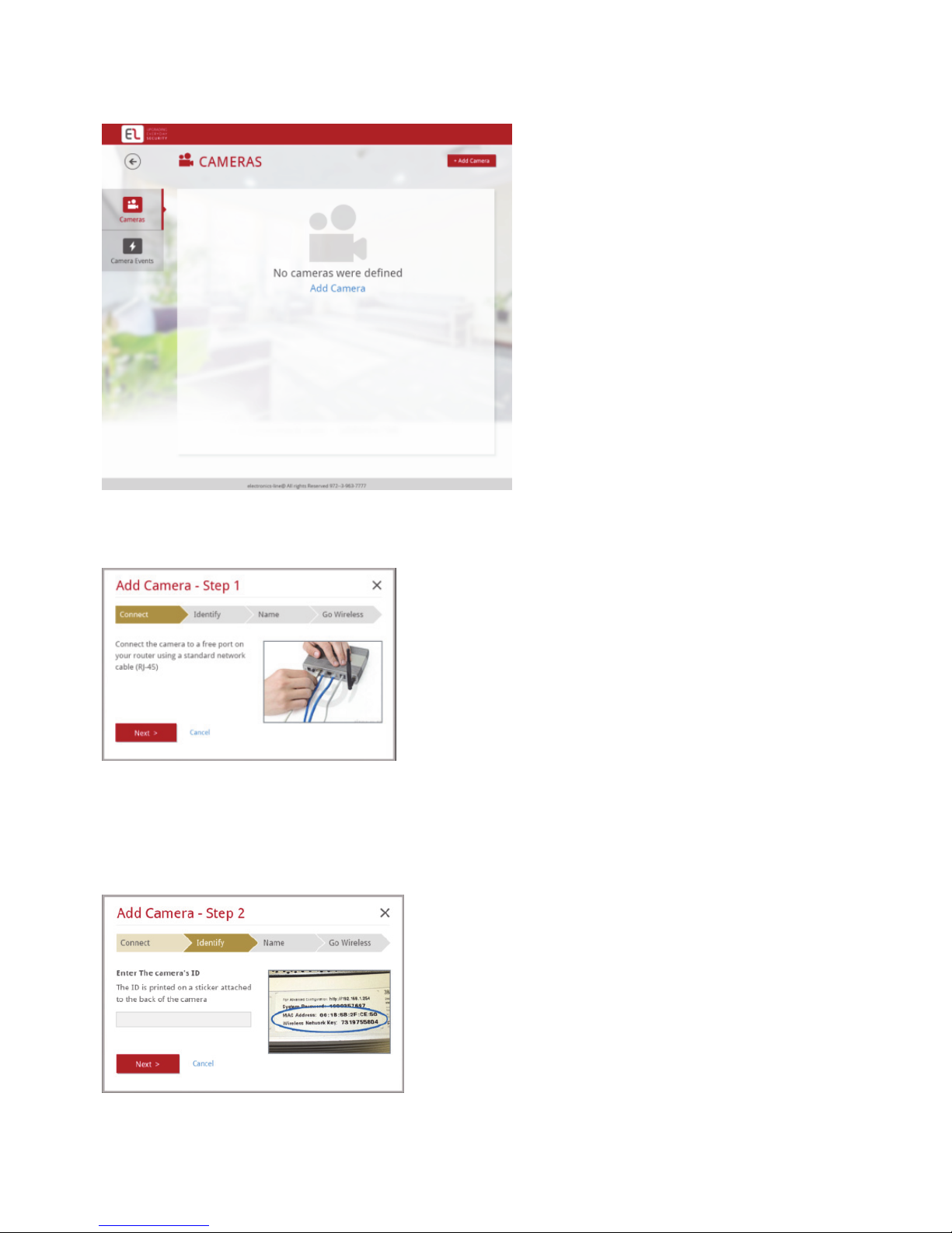
Code) and click the Login button. The Main page is displayed.
Page 11
9
Figure 6 Main page
3. On the Main page, click Cameras, the Cameras page is displayed.
Figure 7 Cameras page
4. Click Add Camera; Step 1 of the Add Camera wizard is displayed.
Figure 8 Add Camera Wizard – Step 1
5. Connect the IP camera to a free port on a compatible AP (Access Point), e.g.
gateway or router and click Next. Step 2 of the Add Camera wizard is
displayed.
Figure 9 Add Camera Wizard – Step 2
Page 12
10
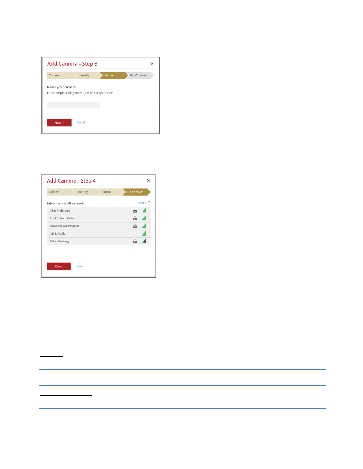
6. Enter the Camera ID (MAC Address) as displayed on the box or on the back
cover of the IP camera and click Next. Step 3 of the Add Camera wizard is
displayed.
Figure 10 Add Camera Wizard – Step 3
7. Enter a name for the camera and click Next. Step 4 of the Add Camera
wizard is displayed.
Figure 11 Add Camera Wizard – Step 4
8. Select one of the following options:
Connect to LAN – to establish a LAN network connection, click Done.
Connect to Wi-Fi – to establish a wireless network connection, select a
wireless network from the available list and click Done.
NOTE
– If your network is password protected, a password must be entered into
the displayed password field.
IMPORTANT
– Once a wireless connection has been established, don’t forget to
disconnect the IP camera from the AP.
Page 13
11
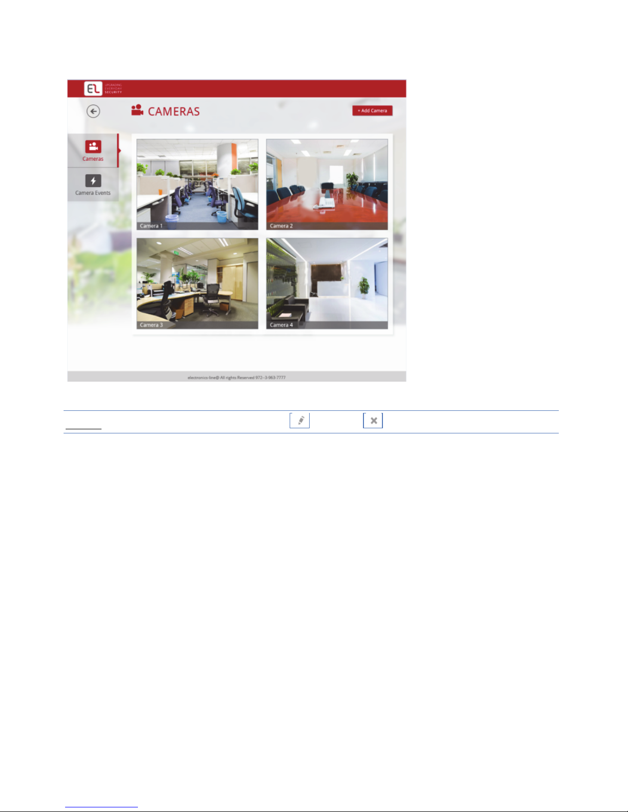
9. Once the camera is ready for use, the defined IP camera is displayed in the IP
Cameras page.
Figure 12 IP Cameras page
NOTE – You also have the option to edit or delete the selected IP camera.
Page 14
12
Defining Camera Event Settings
Any event associated to a specific detector can trigger an alarm.
To define camera event settings:
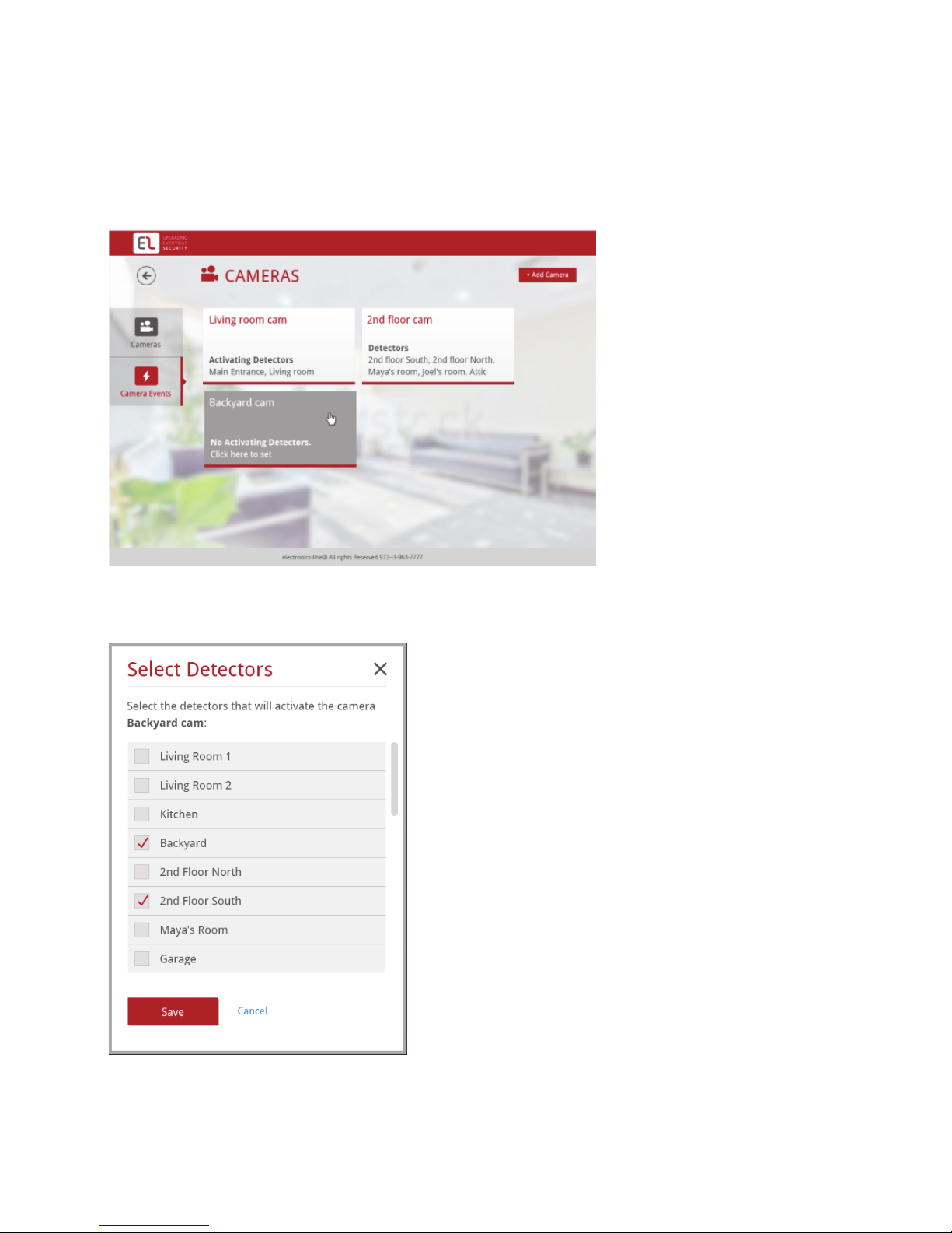
1. On the Main page, click Camera Events, the Camera Events page is
displayed.
Figure 13 Camera Event page
2. Click the required Camera; the Select Detectors dialog box appears.
Figure 14 Select Detector
3. Select the detectors (area) that will be associated to the defined camera.
Page 15
13
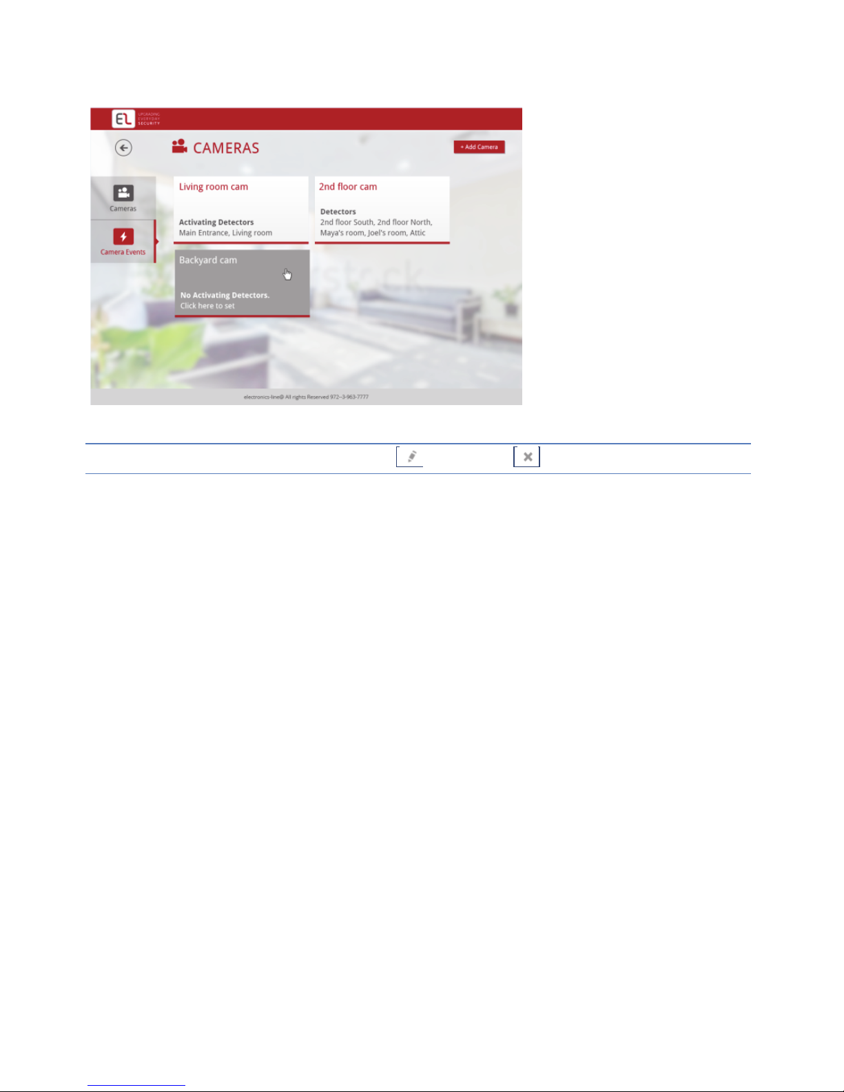
4. Once finished, click Save. The defined camera events are displayed in the
Camera Event page.
Figure 15 Camera Event page
NOTE – You also have the options to edit or to delete the selected camera event.
Page 16
14
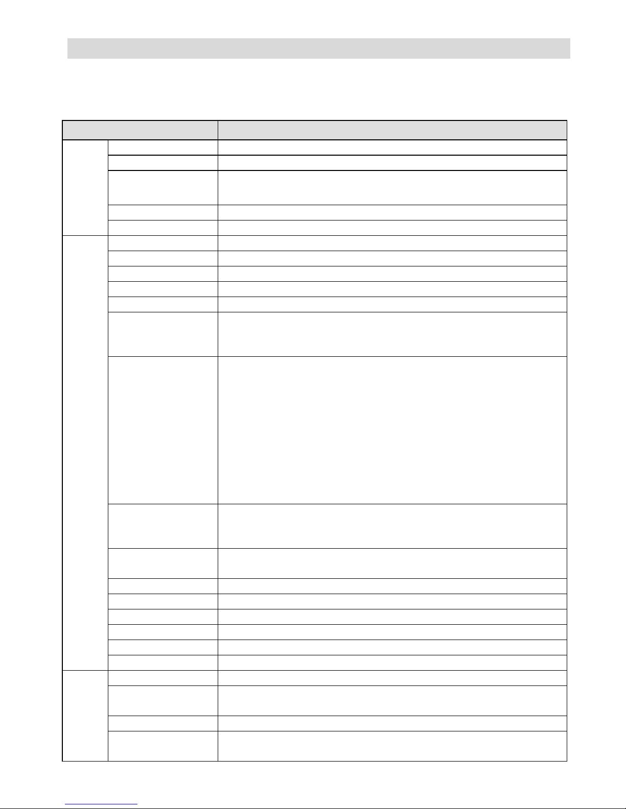
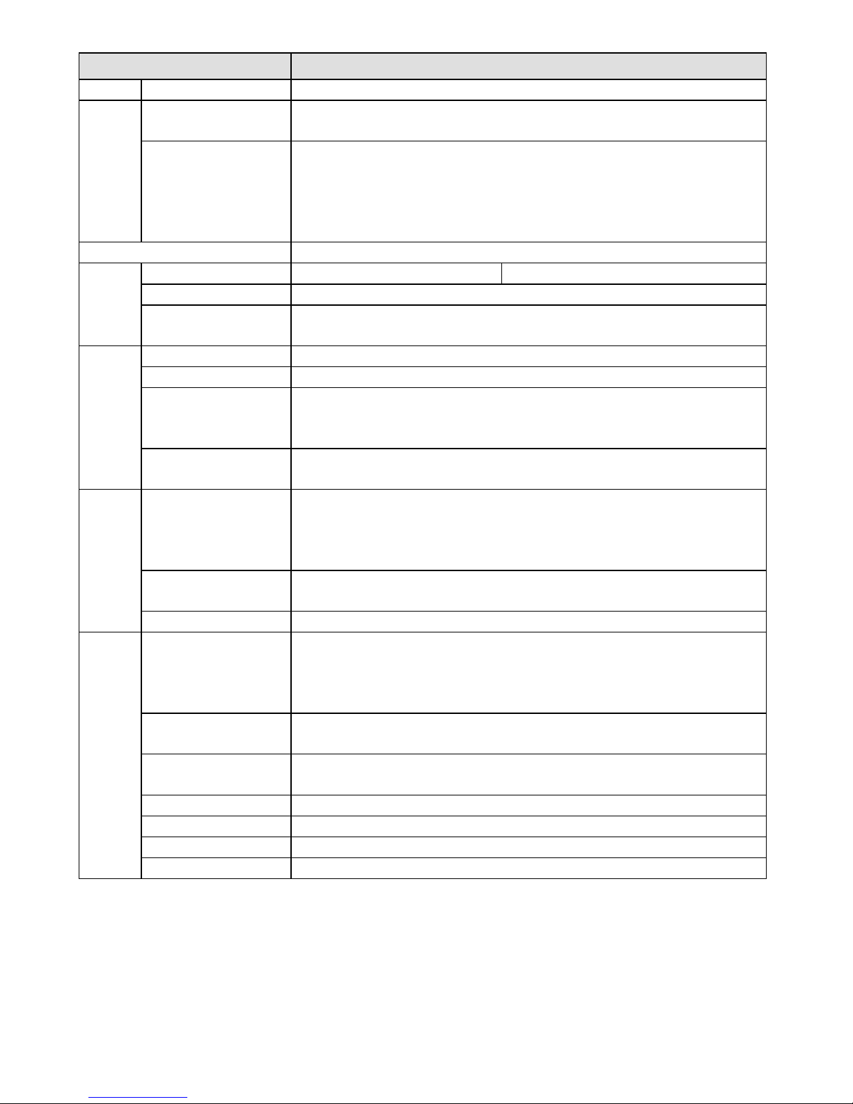
Product Specification
Performance
Please refer to the following table for product performance specification.
Parameter
System
Main Processor TI Davinci high performance DSP
OS Embedded LINU
X
System Resources
Support real-time network monitor, local record, and remote
operation at the same time.
User Interface Remote operation interface such as WEB, DSS, PSS.
System Status Bit stream statistics, log, and software version.
Video Parameter
Image Sensor 1/3-inch CMOS
Pixel 1280(H)*960(V)
Gain Control Fixed/Auto
White Balance Manual/Auto
BLC On/Off
Exposure Mode
Manual/Auto
PAL: It ranges from 1/3 to 1/10000.
NTSC: It ranges from 1/4 to 1/10000.
Video Frame Rate
PAL:
Main stream(1280*960@15fps)
extra stream(352*288@15fps),
Main stream(1280*720@25fps
)
extra stream(352*288@25fps
)
NTSC:
Main stream(1280*960@15fps)
extra stream(352*240@15fps))
Main stream(1280*720@30fps)
extra stream(352*240@30fps)
Video Bit Rate
H.264: 56Kbps-6144Kbps
MJPEG is adjustable and bit rate is adjustable.
Support customized setup.
Video Flip
Support mirror.
Support flip function.
Snapshot Max 1f/s snapshot. File extension name is JPEG.
Privacy Mask Supports max 4 privacy mask zones
Video Setup Support parameter setup such as bright, contrast.
Video Informatio
n
Channel title, time title, motion detect, camera masking.
Lens 3.6mm. Fixed focus. Angle of view: 70°(H) *51.5°(V)
Lens Interface M12. Lens is the default accessories
Audio
Audio Bit Stream Dual-way
Audio Input /
Output
Built-in microphone and speaker
Audio Bit Rate 8kbps 16bi
t
Audio
Compression
G.711A/G.711Mu/PCM
Page 17
15
Parameter
Standard
Video
N/A
N/A
Camera Masking
Sensitivity level ranges from 1 to 6. Each sensitivity level is the
percentage of the privacy mask zone.
Activation event: alarm device, audio/video storage, image snapshot,
log, email SMTP function and etc.
Alarm Port 1-channel input and 1-channel output (on-off )
Record and
Backup
Record Priority Support remote record only Manual>Video detect>Schedule
SD Card Storage Support Micro SD card hot-swap
Storage
Management
Support display network storage status
Network
Wire Network 1-channel wire Ethernet port, 10/100 Base-T Etherne
t
Wireless Network IEEE802.11a/b/g/n, built-in antenna
Network Protocol
Standard HTTP, TCP/IP, ARP, IGMP, ICMP, RTSP, RTP,UDP, RTCP,
SMTP, FTP, DHCP, DNS, DDNS, PPPOE, UPNP, NTP, Bonjour,
SNMP.
Remote Operation
IR light
Monitor, system setup, file download, log information, maintenance ,
upgrade and etc.
AUX Port
Compensation
Light
White light (Max 1W)
Auto turn on white light when an alarm is activated. The light can
last until the alarm ends.
Support compensation light brightness setup via the Web.
N/A
N/A
WPS Click one button to enable WIFI connectio
n
General Parameter
Power
DC 12V and PoE
Warning
!
Do not connect these two power supplying sources to the device at
the same time; it may result in device damage!
Power
Consumption
6W MAX
Working
Temperature
-10~+50
Working Humidify 10%~90%
Dimensions(mm) 66.6*99.5*131.2
Weight 229g( Excluding box)
Installation Installation with the bracket.
Page 18

16
Electronics Line 3000 Ltd. Limited Warranty
EL and its subsidiaries and affiliates ("Seller") warrants its products to be free
from defects in materials and workmanship under normal use for 24 months
from the date of production. Because Seller does not install or connect the
product and because the product may be used in conjunction with products not
manufactured by the Seller, Seller can not guarantee the performance of the
security system which uses this product. Sellers' obligation and liability under
this warranty is expressly limited to repairing and replacing, at Sellers option,
within a reasonable time after the date of delivery, any product not meeting the
specifications. Seller makes no other warranty, expressed or implied, and makes
no warranty of merchantability or of fitness for any particular purpose. In no
case shall seller be liable for any consequential or incidental damages for breach
of this or any other warranty, expressed or implied, or upon any other basis of
liability whatsoever. Sellers obligation under this warranty shall not include any
transportation charges or costs of installation or any liability for direct, indirect,
or not be compromised or circumvented; that the product will prevent any
persona; injury or property loss by intruder, robbery, fire or otherwise; or that
the product will in all cases provide adequate warning or protection. Buyer
understands that a properly installed and maintained alarm may only reduce the
risk of intruder, robbery or fire without warning, but is not insurance or a
guaranty that such will not occur or that there will be no personal injury or
property loss as a result. Consequently seller shall have no liability for any
personal injury, property damage or loss based on a claim that the product fails
to give warning. However, if seller is held liable, whether directly or indirectly,
for any loss or damage arising from under this limited warranty or otherwise,
regardless of cause or origin, sellers maximum liability shall not exceed the
purchase price of the product, which shall be complete and exclusive remedy
against seller. No employee or representative of Seller is authorized to change
this warranty in any way or grant any other warranty.
WARNING: This product should be tested at least once a week.
CAUTION: Risk of explosion if battery is replaced by an incorrect type. Dispose
of used batteries according to local regulations.
Page 19

17
Contacting your Installer / Supplier-Agent
When calling for service, ordering components, or for questions related to your
camera, please contact us for assistance:
Company/agent address,
phone, e-mail address:
Contact / department:
Hours of business:
Website URL:
Company logo:
Other supplier-specific
information:
Page 20
18
Contacting Electronics Line 3000 Ltd.
International Headquarters:
Electronics Line 3000 Ltd.
14 Hachoma St., 75655
Rishon Le Zion, Israel
Tel: (+972-3) 963-7777
Fax: (+972-3) 961-6584
All rights reserved.
No part of this document may be reproduced in any form without prior written
permission from the publisher.
© Electronics Line 3000 Ltd 04/2014 5IN2190
 Loading...