

Page 1

UPCOM TECHNOLOGIES
User Guide
C Band
BLOCK UP CONVERTERS
Model Y
1
Page 2

UPCOM TECHNOLOGIES
Table of Contents
Table of Contents.................................................................................................................................... 2
Outdoor Block Up-Converter - BUC...................................................................................................... 3
User Guide .............................................................................................................................................. 3
Description.......................................................................................................................................... 3
Equipment Supplied............................................................................................................................ 3
General Information............................................................................................................................ 4
Safety Considerations ..................................................................................................................... 4
High Voltage Hazards..................................................................................................................... 4
RF Transmission Hazards............................................................................................................... 4
Inspection........................................................................................................................................ 4
Return of Equipment....................................................................................................................... 4
Ports and Interfaces............................................................................................................................. 5
Prime Power Connection ................................................................................................................ 5
RF Input .......................................................................................................................................... 5
RF Output........................................................................................................................................ 6
M & C Connector............................................................................................................................6
Airflow............................................................................................................................................ 6
Monitors and Controls ........................................................................................................................ 7
Ground (GND)................................................................................................................................ 9
RS-232 / RS-485............................................................................................................................. 9
Monitor and Control Software........................................................................................................ 9
Quick Start Guide ............................................................................................................................. 11
General Maintenance ........................................................................................................................ 12
Basic Cleanliness .......................................................................................................................... 12
Internal Fuse..................................................................................................................................12
Fan Replacement........................................................................................................................... 12
Appendix A – UC 40C Series Y BUC.............................................................................................. 13
2
Page 3

UPCOM TECHNOLOGIES
Outdoor Block Up-Converter - BUC
User Guide
This section provides general information for the UPCOM TECHNOLOGIES line of C BAND
Outdoor SSPA Based - BUCs. The Outdoor BUC Series Y has been designed and
manufactured to be extremely robust and reliable. It is well suited for harsh outdoor
environments.
Description
Please refer to Appendix A for the appropriate product data sheet and specifications.
The Outdoor BUC Series Y is a one-piece integrated Block Up Converter and amplifier system.
It includes the AC / DC Power Supply, L Band to C Band Up-Converter module, microwave
Booster Amplifier Module, microcontroller based monitor (optional) and control circuitry, and
an efficient thermal management system.
The reduced size and weight of this system allow it to be used in a wide variety of installations;
many of which historically precluded the use of solid state units. This system is ideal for
mounting on the boom of small antennas or anywhere that size and weight are a major
concern.
Features include:
Compact size
Light weight
Auto-Sensing Power Supply
Output Power Detection
Optional Internal 1:1 Redundant Capability
Serial (RS-232 / RS-485) Monitor & Control Circuitry
Windows Monitor & Control Software
Optional gain control (on selected configurations)
Equipment Supplied
The following equipment is supplied with each unit:
The Outdoor BUC Assembly
Prime Power Mating Connector
M & C Mating Connector (where applicable)
CD with UPCOM TECHNOLOGIES Monitor & Control Software (where applicable)
3
Page 4

UPCOM TECHNOLOGIES
General Information
Safety Considerations
Potential safety hazards exist unless proper precautions are observed when working with this
unit. To ensure safe operation, the user must follow the information, cautions, and warnings
provided in this manual as well as the warning labels placed on the unit itself.
High Voltage Hazards
Only qualified service personnel should service the internal electronic circuitry of the Outdoor
BUC. High DC voltages are present in the power supply section of the amplifier. Care must be
taken when working with devices that operate at this high voltage levels. It is recommended to
never work on the unit or supply prime AC power to the unit while the cover is removed.
RF Transmission Hazards
RF transmissions at high power levels may cause eyesight damage and skin burns. Prolonged
exposure to high levels of RF energy has been linked to a variety of health issues. Please use
the following precautions with high levels of RF power.
Always terminate the RF input and output connector prior to applying prime AC input
power.
Never look directly into the RF output waveguide.
Maintain a suitable distance from the source of the transmission such that the power
density is below recommended guidelines in ANSI/IEEE C95.1. The power density
specified in ANSI/IEEE C95.1-1992 is 10 mW/cm². These requirements adhere to
OSHA Standard 1910.97.
When a safe distance is not practical, RF shielding should be used to achieve the
recommended power density levels.
Inspection
When the unit is received, an initial inspection should be completed. First ensure that the
shipping container is not damaged. If it is, have a representative from the shipping company
present when the container is opened. Perform a visual inspection of the Outdoor Amplifier to
make sure that all items on the packing list are enclosed. If any damage has occurred or if
items are missing, contact: UPCOM TECHNOLOGIES Inc.
Return of Equipment
When returning items back to UPCOM TECHNOLOGIES for replacement or repair, please
prepare the following information:
A written description of the problem encountered.
The part number and serial number of the unit in question.
Once this information is ready, please contact UPCOM TECHNOLOGIES for a Return Material
Authorization (RMA) number and shipping instructions.
4
Page 5

UPCOM TECHNOLOGIES
Ports and Interfaces
Prime Power Connection
The Prime Power Connector is the point where the unit receives input power.
The AC input can operate over a range of 90 - 260 VAC, at 47 - 63 Hz. This connector is a 3
(three) pin circular connector 3100A 14S-7P and the mating connector is supplied with the
unit
Pin Circuit
A - C 110/220V (90-260V) AC
B
It’s recommended that the BUC should be powered from a 180 - 260 VAC source.
This will keep AC line currents to a safe operating level and minimizes cable losses.
In some cases, the unit may only be specified to operate at higher input voltage levels – please
check the labels or accompanying Test Record for this information.
When wiring up the mating connector, carefully follow the pin descriptions noted in the
accompanying Test Record. Incorrect connections can seriously damage the unit. It is
highly advisable that the installer checks all the pins at the AC connectors for
resistance to the chassis ground to make sure that the live and ground pins are
correctly identified .
Please contact the factory if there are any questions regarding these input connections.
Ground
RF Input
The RF Input is an N type connector. The input frequency is L Band. Nominal RF input
levels are -50 to 0 dBm, depending on the output power level and the system gain of the unit.
The maximum input level should be limited to 0 dBm to avoid damaging the unit.
Attention: This BUC Series Y does not require DC Voltages at the L Band Input Port.
DO NOT INPUT DC VOLTAGES!
10MHz Reference is required at the L Band Input .
5
Page 6
UPCOM TECHNOLOGIES
RF Output
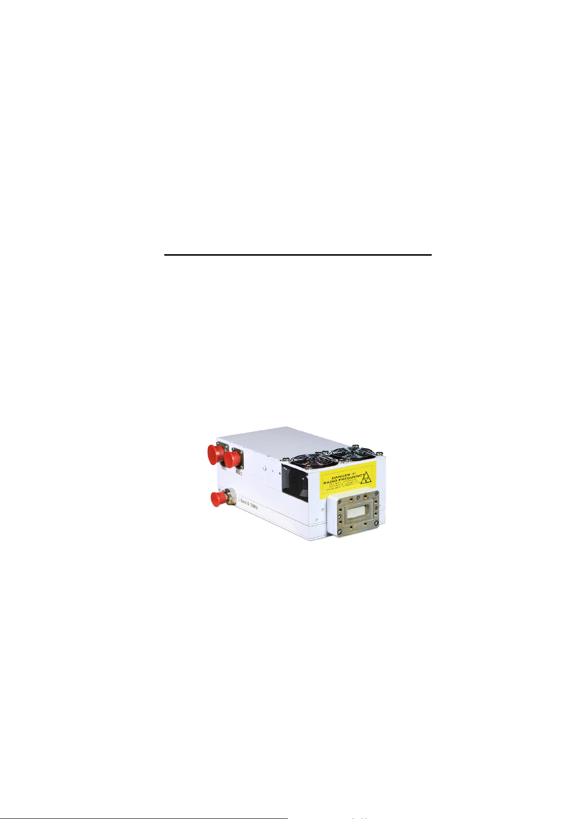
The RF Output is provided at a waveguide flange in the Outdoor BUCs. The C Band BUCs
have CPR style grooved flange (CPR-137G). An isolator is provided at the output flange with a
termination capable of handling full reflected output power.
Caution should be observed here to make sure that the antenna or a suitable termination
(dummy load) is connected to this port before operating the BUC. The BUC is protected
against reflection but dangerous levels of microwave energy can be present at this port. The
output of the BUC should be connected to the antenna feed by means of flexible or rigid
waveguides. The use of coaxial cables and adapters is not recommended and it will void the
equipment warranty .
Never look directly into the RF output waveguide.
M & C Connector
The Monitor and Control (M & C) connector is the primary interface point for controlling the
BUC and monitoring fault conditions. It also provides control to a waveguide switch in
Redundant configurations
A Redundant configured unit may be operated in stand-alone mode, and behaves in a similar
way to a normal Microcontroller equipped unit. If this is done, it is important to cover the
Redundancy Port to protect it from the external environment, since there are live voltages
present on this interface. Never connect anything except for the supplied cables to this
interface port.
Airflow
The air intake and exhaust are both located on the bottom side of the BUC. The intake is
brought through one or two fans ( two fans on 50 watts units KU Band and higher and one fan
on lower power units) while the exhaust is along the rows of heat-sink fins.
A minimum clearance of 12 inches (305 mm) should be maintained between the air intake of
the Outdoor BUC and exhaust during operation. This will ensure that there is no forced recirculation of airflow from exhaust to intake.
Some lower output power units are not equipped with a fan, but the same clearance stated
above must be kept around the unit for proper operation.
6
Page 7

UPCOM TECHNOLOGIES
Monitors and Controls
Monitor signals and Control lines are present on the M & C Connector when this option is
installed. With a Microcontroller equipped system, all Monitors and Controls can also be
accessed remotely by RS-232 / RS-485 to a Windows based PC; and other Alarms become
available as well. Units equipped with a Redundancy option have a Microcontroller M & C
installed by default.
The full M & C Connector pin-out is listed here for convenience. However, always check the
Test Bench Record supplied with the unit to view which interfaces have been installed on your
unit, or to see if it has had any custom modifications.
7
Page 8
UPCOM TECHNOLOGIES
Connectors Pin-out
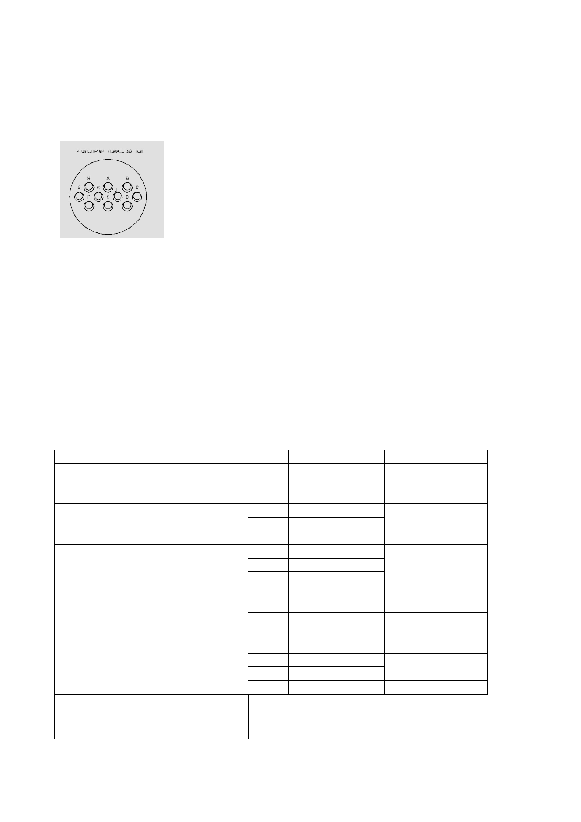
J4 M&C connector 10pin PT02 E12-10P
RS 485 RS 232
A Rx+ J Rx
B Rx- K Tx
C Tx+ G GND
D Tx- COM port setting: 9600 bps, 8 bit, 1 stop bit
J5 Redundancy SWOV connector 10pin PT02 E12-10P
A SW COMMAND 1 F SW POS 2
B COMMON G ALARM OUT
C SW COMMAND 2 H ALARM IN
D SW POS 1 J MODE OUT
E COMMON POS K MODE IN
General Connectors Pin Assignment
Connector Name Type Pin # Signal Remarks
J1 “IF IN” WR-75 N/A
J2 “RF OUT” WR-75 N/A RF Output 47.0 dBm max
J3 “AC POWER
IN”
J4 “M&C
Interface”
J5
97-3100A-14S-7P
3 pin male
PT02E12-10P-027
10 pin male
LED
A Line (AC)
B Ground
C Neutral (AC)
A Rx+ In
B Rx- In
C Tx+ Out
D Tx- Out
E Detector Optional
F Alarm Out Low when alarm
G GND
H Mute In Muted when Low
J Rx In
K Tx Out
N/A Green – normal
RF Input
BUC OUT
Green blinking – mute
Red – alarm
33 dBm, max
110/220VAC
90-260V
RS-485
RS-232
8
Page 9

UPCOM TECHNOLOGIES
Ground (GND)
This pin is connected to the chassis, which also represents the main Ground of the unit.
The installation of the BUC at the antenna and the signal and AC cables running from the BUC
to the building should be properly grounded to avoid power surges that may damage the
equipment.
All antennas shall be grounded locally.
All cable entries at the building shall be grounded at building entry.
Cable entry ground shall be connected to building ground by AWG#4 copper wire.
Cable entry ground shall be connected to antenna ground by AWG#4 copper wire.
PLEASE MAKE SURE THAT THE UNIT AND CABLES ARE
PROPERLY GROUNDED TO AVOID DAMAGES TO THE
EQUIPMENT AND RISK TO PERSONEL ! – DAMAGES DUE
TO POWER SURGES WILL VOID THE WARRANTY!
RS-232 / RS-485
This serial link is normally used to communicate with a remote PC running UPCOM
TECHNOLOGIES Monitor and Control Software. This enables a simple way to view / control
the Monitors and Controls listed above, and also enables the functions listed below.
Normally, either RS-232 or RS-485 is available at any one time (both interfaces cannot be
used simultaneously). Communication links using RS-232 are typically good up to 30 ft. (9 m)
in length. Installations exceeding this length should use the RS-485, which will allow serial
control up to 4000 ft. (1200 m).
Monitor and Control Software
UPCOM TECHNOLOGIES Monitor and Control Software is provided on CD for units equipped
with an onboard Microcontroller system. A Windows based PC uses this software to remotely
monitor and control the BUC through its serial port.
Various Monitors and Alarms are displayed along the left hand side of the interface. If a
problem has been detected, it will be displayed in red, and the Block Up Converters (BUC) will
be placed into a muted state.
Installation Instructions
System Requirements:
PC running Windows 98, Me, 2000, or XP (NT 4.0 with Service Pack 6a)
Display resolution of 800 x 600 or greater
Free serial port (RS-232 or RS-485)
Microsoft .NET Framework.
Compatibility under Windows Vista has not been tested.
9
Page 10

UPCOM TECHNOLOGIES
Status Display
This indicator shows the general status of the Outdoor BUC – if everything is good, or if an
error condition has occurred, or if the unit has been manually disabled by mute control. Also,
the operating status of a Master/Slave redundant pair is reflected.
Temperature Display
Using the UPCOM TECHNOLOGIES Monitor and Control Software, a thermometer display
with a numeric readout of the base-plate temperature of the unit in degrees Celsius is shown.
The base-plate temperature typically experiences a 20 to 30 degree rise above ambient on the
highest power Outdoor BUCs and 15 to 20 degree rise on lower power units. This display
corresponds with the Temperature Monitor outlined in the analog M&C section above.
Output Power Display
A numeric readout of the output power level is displayed in units of dBm. The indicator is
calibrated at the factory using the middle frequency of the BUC, and has approximately a 20
dB dynamic range. When this range is exceeded, the readout shows “Low” or “High”
depending on which particular limit has been reached.
PS Voltages Monitor
The output voltage levels of the Power Supply are monitored and this alarm indicates when
any of them fall below a preset level. The unit will enter a muted state when this alarm is
active.
Manual Control Enable/Disable and Mute Input
A manual mute control can be accessed from the Enable/Disable button of the software. For
systems set up for 1:1 Redundant operation, this control is also used for manually selecting the
Active unit in a redundant pair.
Communication Status
The communication status between the software and the BUC is reflected here. If there is a
problem here, double-check all serial port connections and ensure the correct Com port is
selected (the software uses the Select Port menu item).
10
Page 11

UPCOM TECHNOLOGIES
Quick Start Guide
Connect the low power L Band output from a modulator or a 10MHz Insertion Box to
the BUC Input port.
Nominal input levels are approximately -50 to 0 dBm depending on the output power
level of the unit.
DO NOT FEED DC VOLTAGES TO THE L BAND INPUT
The BUC’s output is taken from the waveguide port (RF Out). Caution should be
observed here to make sure that the antenna or a suitable termination is connected to
this port before operating the BUC.
Ensure there is proper clearance around the unit.
Connect the chassis ground to a proper ground connection
Connect AC Input power to the connector. The unit will be enabled almost immediately,
provided it is not forced into a mute state.
Optional - Connect the M & C interface to an available COM port on your computer
and/or to your analog based monitoring and control equipment.
Optional - Run the UPCOM TECHNOLOGIES Monitor and Control Program.
Recommendation: if possible install the BUC with the fans facing down in order
to avoid accumulation of debris inside the fans that may block the fans.
11
Page 12

UPCOM TECHNOLOGIES
General Maintenance
With proper care and maintenance, your BUC will provide many years of reliable service.
Please follow these maintenance guidelines so that your equipment will provide you with the
maximum amount of trouble-free service.
Basic Cleanliness
The exterior chassis of the BUC acts as a large heatsink that must dissipate at least a few
hundred Watts. Excessive dirt, dust, debris, and sand accumulated on the chassis surface will
impede its ability to dissipate heat, and will result in higher internal temperatures, potentially
shortening the BUC lifespan.
Periodically inspect the chassis for excessive dirt, and remove as necessary. A brush
combined with compressed air is the safest way to clean the unit. Also, inspect the fan
assembly for any dirt or debris that also might impede airflow.
Internal Fuse
The internal power supply is protected by a fuse to prevent excessive input current
consumption. Contact the factory if you suspect the internal fuse has tripped, and instructions
will be sent on how it can be replaced.
Fan Replacement
Normally the fan on the unit operates continuously when input power is connected to the unit.
If the fan stops turning, and the BUC still provides an output signal when it is cool, it is time to
replace the fan. Immediately remove power to the unit the prevent damage by overheating.
Contact the factory to order the correct replacement fan for your particular model.
The fan is encased in a shroud to direct airflow to the chassis heatsink fins. First remove the
shroud from the main chassis using the screws at each side of the chassis. The fan and
shroud assembly will be connected by wires to the main chassis. Disconnect the wire
connection by pulling apart the inline (wire to wire) connector.
Next, remove the screws holding the fan to the shroud and fan grille. Remove the fan, and
install the replacement fan in reverse order as described above.
12
Page 13

UPCOM TECHNOLOGIES
Appendix A – UC 40C Series Y BUC
Input Frequency Range 950 – 1700 MHz
Operating Frequency Range 5.85 – 6.60 GHz
Output Power 46 dBm ( 40 watts )
Input Power @ P1dB output - 20 dBm nominal
Input Power range without damage 0 dBm MAX
Input Return Loss > -16 dB
Gain 65 dB min
Gain flatness 2.0 max
I/O VSWR -15 dB
Gain flatness 40MHz 0.3 dB
Gain Variation Over Temperature 3 dB max
Spurious @ P1dB -55dBc max
IMD (With 2 carriers @6dB backoff 1dB Comp) -27dBc max
Power supply AC 220V ±20%, 50/60Hz
Operating Temperature -40 °C to 55 °C
Relative Humidity up to 98%
Weight ( 40 watts C ) 5 kg
Dimensions ( 40 watts C) 257x140x95mm
Phase Noise < -30 dBc/Hz at 10 Hz
< -60 dBc/Hz at 100 Hz
< -70 dBc/Hz at 1 kHz
< -80 dBc/Hz at 10 kHz
< -90 dBc/Hz > 100 kHz
External Reference Required 10MHz Sine wave
Reference Input Level - 5 to +5 dBm
13
 Loading...