

Page 1

UC-IRD+ MULTI-MODE RECEIVER / DECODER
USER MANUAL
UPCOM TECHNOLOGIES INC.
www.upcom.com
Version 1.07 05312011
Page 2

TABLE OF CONTENTS
!"#$%"#&'($&%)$*"+%$,-.&-'$////////////////////////////////////////////////////////////////////////////////////////////////$0!
1)2".+2-'$%3)2+4+2-*+#.%$////////////////////////////////////////////////////////////////////////////////////////////////////////$0!
1")$5-*)''+*)$6)2)+7)8$//////////////////////////////////////////////////////////////////////////////////////////////////////////////////////$0!
Front!of!Unit!.......................................................................................................................................................!4!
Back!of!Unit!........................................................................................................................................................!4!
Summary!of!Features!.....................................................................................................................................!5!
Inputs:!...................................................................................................................................................................!5!
Outputs:!...............................................................................................................................................................!6!
9#:)8+.;$<.$1")$=>&+3,).*$///////////////////////////////////////////////////////////////////////////////////////////////$?!
5:+*2"+.;$<.$///////////////////////////////////////////////////////////////////////////////////////////////////////////////////////////////////////$?!
@8#.*$9-.)'$A+%3'-B$//////////////////////////////////////////////////////////////////////////////////////////////////////////////////////////$?!
@8#.*$9-.)'$C).&$5*8&2*&8)$-.($D-7+;-*+#.$///////////////////////////////////////////////////////////////////////////$E!
5)')2*+.;$-$,).&$#3*+#.$//////////////////////////////////////////////////////////////////////////////////////////////////////////////////$E!
@8#.*$9-.)'$<3)8-*+#.$///////////////////////////////////////////////////////////////////////////////////////////////////////////$E!
5B%*),$5*-*&%$//////////////////////////////////////////////////////////////////////////////////////////////////////////////////////////////////////$E!
6)2)+7)($5+;.-'$5*8).;*"$F.(+2-*#8 (RSSI)$/////////////////////////////////////////////////////////////////////////////$G!
5)**+.;$H3$5-*)''+*)$F.I#&.($JAKLM5NO$///////////////////////////////////////////////////////////////////////////////////////$G!
5)**+.;$H3$=*")8.)*$F.I#&.($/////////////////////////////////////////////////////////////////////////////////////////////////////////$P!
5)**+.;$H3$*")$Q#,,#.$F.*)84-2)$JA)M528-,I'+.;O$///////////////////////////////////////////////////////////$RS!
5)**+.;$H3$*")$TUK$A)2#()8$////////////////////////////////////////////////////////////////////////////////////////////////////////$RR!
5).(+.;$*")$%*8)-,$*#$*")$T5F$#&*3&*%$////////////////////////////////////////////////////////////////////////////////////$R0!
5)**+.;$&3$LF55$/////////////////////////////////////////////////////////////////////////////////////////////////////////////////////////////////$R0!
Q#.4+;&8+.;$*")$+.*)8.-'$CHV$////////////////////////////////////////////////////////////////////////////////////////////////////$RW!
Q#.4+;&8+.;$=*")8.)*$5*8)-,+.;$///////////////////////////////////////////////////////////////////////////////////////////////$R?!
For!DVB!Mode:!...............................................................................................................................................!18!
For!IPTV!Mode:!..............................................................................................................................................!18!
Q#.4+;&8+.;$*")$HQMF6AX$C-.-;),).*$9#8*$//////////////////////////////////////////////////////////////////////////$RP!
Q#.4+;&8+.;$*")$!)I$F.*)84-2)$///////////////////////////////////////////////////////////////////////////////////////////////////$NS!
@+.($*")$&.+*$%#4*:-8)$7)8%+#.%$/////////////////////////////////////////////////////////////////////////////////////////////////$NR!
6)%)*$*")$HQMF6AX$*#$@-2*#8B$A)4-&'*$Q#.4+;&8-*+# .$/////////////////////////////////////////////////////////$NR!
!)I$<3)8-*+#.$//////////////////////////////////////////////////////////////////////////////////////////////////////////////////////$NY!
Z#,)$9-;)[$///////////////////////////////////////////////////////////////////////////////////////////////////////////////////////////////////////$NY!
5)**+.;$H3$5-*)''+*)$F.I#&.($JAKLM5NO$////////////////////////////////////////////////////////////////////////////////////$N0!
5)**+.;$H3$*")$Q#,,#.$F.*)84-2)$JA)M528-,I'+.;O$///////////////////////////////////////////////////////////$NW!
5)**+.;$H3$*")$TUK$A)2#()8$////////////////////////////////////////////////////////////////////////////////////////////////////////$N?!
5).(+.;$*")$%*8)-,$*#$*")$T5F$#&*3&*%$////////////////////////////////////////////////////////////////////////////////////$YS!
5)**+.;$&3$LF55$/////////////////////////////////////////////////////////////////////////////////////////////////////////////////////////////////$YR!
Q#.4+;&8+.;$*")$+.*)8.-'$CHV$////////////////////////////////////////////////////////////////////////////////////////////////////$YY!
Q#.4+;&8+.;$=*")8.)*$5*8)-,+.;$///////////////////////////////////////////////////////////////////////////////////////////////$Y0!
For!DVB!Mode:!...............................................................................................................................................!36!
For!IPTV!Mode:!..............................................................................................................................................!36!
Page 3

UC-IRD+ MULTI-MODE RECEIVER / DECODER
3
A)7+2)$F.4#8,-*+#.$////////////////////////////////////////////////////////////////////////////////////////////////////////////////////////$YE!
5#4*:-8)$K)8%+#.$////////////////////////////////////////////////////////////////////////////////////////////////////////////////////////////$YG!
D)*:#8\$Q#.4+;&8-*+#.$/////////////////////////////////////////////////////////////////////////////////////////////////////////////////$YG!
Z119$]#;+.$///////////////////////////////////////////////////////////////////////////////////////////////////////////////////////////////////////$YP!
D)*:#8\$1+,)$98#*#2#'$Q#.4+;&8-*+#.$////////////////////////////////////////////////////////////////////////////////////$YP!
TDD=V$T$///////////////////////////////////////////////////////////////////////////////////////////////////////////////////////////////////$0S!
F6A$C=DH$516HQ 1 H 6 =$/////////////////////////////////////////////////////////////////////////////////////////////////////////////////$0S!
TDD=V$L$///////////////////////////////////////////////////////////////////////////////////////////////////////////////////////////////////$0R!
T=5$L-'-.2)($T&(+#$9+.#&*$/////////////////////////////////////////////////////////////////////////////////////////////////////////$0R!
Page 4

UC-IRD+ MULTI-MODE RECEIVER / DECODER
4
Who$should$use$this$manual$
This manual is written for operators/users of the UC-IRD+ Professional
Integrated Receivers / Decoders. It describes the unit’s functions and operation.
Technical$specifications$$
Advanced HD/SD Integrated Receiver are designed with ease of use and
reliability in mind.
Most advanced features found as optional on other receivers come as
standard on UPCOM’s line
The$Satellite$Receiver$
The UC-IRD+ interfaces directly to Low-Noise Block (LNB) and accepts
frequencies in L band (950-2150MHz). The unit can provide DC power to the LNB.
Front$of$Unit$
Back$of$Unit$
Page 5

UC-IRD+ MULTI-MODE RECEIVER / DECODER
5
$
Summary$of$Features$$
DVB-S/S2 and IP Receiver
• MPEG-2(MP@ ML& MP@HL)and MPEG 4 Part 10 (AVC high profile level
4.1) standards compliant and decoding
• Wide choice of I/O interfaces, including ASI input/output, CVBS output,
YPbPr output, HDMI output, SD/HD-SDI output (embedded 2 pairs stereos
audio), AES/EBU output, 10/100M or 100/1000M TS over IP input/output
(optional), DS3 interface (optional)
• DS3 in/out interface is compatible with Barco, Huawei protocols
• Built-in re-multiplexer
• BISS 1 or BISS E decryption
• Dynamic PMT detection and automatic update
• VBI TELETEXT, EBU/ DVB SUBTITLE support
• WSS support
• Closed caption support
• 10/100M Ethernet TSoIP I/O, compatible for future Gigabit Ethernet
daughter board
• UDP and RTP for TS over IP I/O
• DVB and IPTV mode IP output
• Unicast and Multicast support
• Control and surveillance over WEB or HDMS software remotely
• Two DVB-CI slots, support multiple programs decryption• Compatible
with: Conax, Cryptoworks, Irdeto, NDS, Mediaguard, SECA, Viaccess and
more
• Teletext VBI, EBU, DVB and CC support
Inputs:$
Tuner IN
1×input, 1×loop through output
ASI IN
2× BNC Female,75Ω
Ethernet Connector
1×RJ45, 10/100M, for TS over IP
DVB$S2'Demodulation:'
Input Frequency Range
950〜2150MHz
Input Level
-25〜-65dBm
Input Impedance
75Ω
Connector
F-type female
Symbol rate
2〜45MBauds for QPSK
Page 6

UC-IRD+ MULTI-MODE RECEIVER / DECODER
6
2〜45MBauds for 8PSK
Rolling off factor
0.35 for QPSK
0.35,0.25,0.2 for DVB-S2
Punctured rates
DVB-S QPSK:1/2,3/5,2/3,3/4,4/5,5/6,8/9,8/10
DVB-S2 8PSK:3/5,2/3,3/4,5/6,8/9,9/10
LNB Level
0,13V,18V adjustable
0/22K
0/22KHz selectable
DiSEqC
DiSEqC 1.0
Outputs:$
ASI OUT
2×2 BNC Female,75Ω
SDI OUT
2×BNC Female,75Ω; supports HD-SDI/SD-SDI,(one for back-up)
HDMI
1x HDMI 1.3 interface
YPbPr
1
CVBS
1×RCA,1xBNC
AES/EBU
2×9-pins D-sub connector,AES/EBU and XRL audio output ports
Serial Port
1×RS-232 9-pin D-sub
Ethernet Connector
1×RJ45, 10/100M, for network management
1×RJ45, 10/100M, for TS over IP
Powering$On$The$Equipment$
Switching$On$
Caution: This equipment should not be operated unless the cooling fan is
working and there is free-air flow around the unit.
Front$Panel$Display$
There is a 2×20 character LCD in front panel. After loading the software, it will
show some information. The first line is the system name and the second line is
the IP address of the device.
UC-IRD+
IP:192.168.0.60
Page 7

UC-IRD+ MULTI-MODE RECEIVER / DECODER
7
Front$Panel$Menu$Structure$and$Navigation$
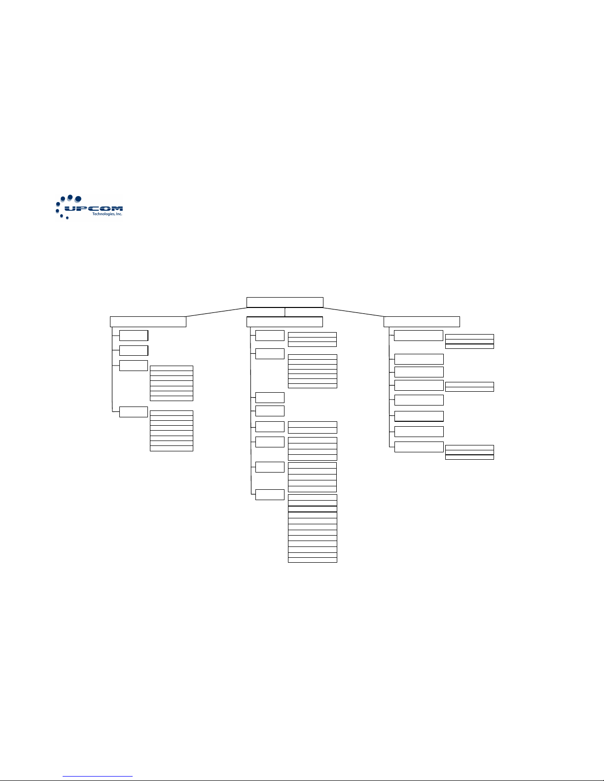
The operations menu has four levels (See Annex A). The first level menu has
three menu items, each has its own child menu. And the child menu can have its
own child menus again.
Selecting$a$menu$option$
To navigate the menu you will need to use the UP, DOWN, LEFT and RIGHT
pushbuttons on the front of the UC-IRD+. To select an option or enter a sub
menu you must press the ENTER pushbutton. To go back on the menu or cancel
a change press the EXIT pushbutton.
The parameters can be changed following this steps:
1. Press “ENTER” to go into a menu, sub-menu or to enter the edit mode.
2. Use the UP, DOWN, LEFT and RIGHT pushbuttons to make changes on
the configuration. After changing parameter, press “ENTER” and return to
main menu to save the setting.
3. No matter how the configuration is changed, press “EXIT” to return to the
previous level menu.
Front$Panel$Operation$
System$Status$
This menu will show the status of the system.
Operations Sequence:
Click “ENTER” to enter the “Inputs” menu, select “Status” then click
“ENTER”. The display will show something like this:
ASI1 Unlock
ASI2 Unlock
Page 8

UC-IRD+ MULTI-MODE RECEIVER / DECODER
8
The screen is for information only, parameters cannot be changed on this
screen.
Received$Signal$Strength$Indicator (RSSI)
This menu allows you to check the inbound strength parameters.
Operations Sequence:
Click “ENTER” to enter the “Inputs” menu, select “RSSI” then click
“ENTER”. The display will show something like this:
The screen is for information only, parameters cannot be changed on this
screen.
Setting$Up$Satellite$Inbound$(DVBJS2)$
This menu allows you to configure the Satellite Receiver. The parameters
must be known before starting. (Please contact your satellite provider if
you don’t have them)
Operations Sequence:
Click “ENTER” to enter the “Inputs” menu, select “DVB-S2” then click
“ENTER”. The display will show something like this:
LNB Frequency
5150MHz
Tuner Unlock
Strength -95.0dBm
Page 9

UC-IRD+ MULTI-MODE RECEIVER / DECODER
9
There are 7 options to setup on this menu:
LNB Frequency: The input LNB Frequency
Satellite Frequency: The input downstream frequency of the satellite
Symbol Rate: The input symbol rate for the stream
LNB Voltage: The voltage that will be sent through the F-Connector for
the LNB. Please select the correct option: Off, 13V, 18V.
LNB 22KHz: To activate the LNB 22KHz control signal. Options are: On,
Off.
DiSEqC: To activate or deactivate DiSEqC support. Options are: OFF/Port
A/Port B/Port C/Port D.
PLS Gold Code: 6 digit decimal Physical Layer Signalling
Setting$Up$Ethernet$Inbound$$
This menu allows you to configure the TS/IP port as input if activated on
System->Optional Function. The parameters must be known before
starting. (Please contact your stream provider if you don’t have them)
Operations Sequence:
Click “ENTER” to enter the “Inputs” menu, select “Ethernet” then click
“ENTER”. The display will show something like this:
There are 8 options to setup on this menu.
Stream IP Address: Enter the IP address assigned to your equipment
TS/IP input.
Stream Netmask: Enter the network netmask for the IP address assigned
to your equipment TS/IP input.
Stream IP Address
16.16.16.16
Page 10

UC-IRD+ MULTI-MODE RECEIVER / DECODER
10
Stream Gateway: Enter the gateway address for the IP address assigned
to your equipment TS/IP input.
Stream MAC Address: The Factory-Set MAC address assigned to the TS/IP
port.
Multicast IP Address: Enter the multicast IP address of the Transport
Stream source.
Multicast UDP Port: Enter the UDP port of the Transport Stream source.
Protocol: Select the multicast protocol: UDP or RTP.
Output Smoothing: Set the quality of the Transport Stream that arrives to
TS/IP input
Auto: detects the bit rate.
Disable: the equipment lets the Transport Stream to pass by.
Fixed Rate: use a fixed bit rate.
Setting$Up$the$Common$Interface$(DeJScrambling)$
This menu allows you to configure the Common Interface for inbound DeScrambling.
NOTE: Configure either the Satellite Inbound or Ethernet Inbound first
and make sure the input is locked to use it as your CI Source
Operations Sequence:
Click “ENTER” to enter the “Outputs” menu, select “CI” then click “ENTER”.
The display will show something like this:
There are 3 options to setup on this menu.
CI Source
1-TUNER
Page 11

UC-IRD+ MULTI-MODE RECEIVER / DECODER
11
CI Source: Select the input source for the CI module. The options are:
Tuner, ASI1, ASI2, IP input (If the TS/IP port is set to “IP in” on System > Optional Function).
Setup: Programs will be shown from the stream to be selected. Select the
program to be de-scrambled. Un-scrambled programs are marked as
“free”. Three different statuses could be set for each program:
Slot 1: Use the upper CAM to De-Scramble.
Slot 2: Use the lower CAM to De-Scramble.
Bypass: Do not De-Scramble the stream.
The status will show up on the first row of the screen. Confirm the
selected setup before leaving the sub-menu.
The De-Scrambled stream will be ready to be used for the other functional
blocks like the Decoder, ASI1, ASI2, SDI, Mux and TS/IP Output.
Setting$Up$the$A/V$Decoder$
This menu allows you to configure the output of the UC-IRD+.
NOTE: All the other configurations must be done before like BISS, CI, and
Input configurations.
Operations Sequence:
Click “ENTER” to enter the “Outputs” menu, select “Decoder” then click
“ENTER”. The display will show something like this:
There are 7 options to setup on this menu.
Source: Select the source of the output. The output will be sent to
all the output ports on the back of the equipment with exception of
Decoder
Source ->
Page 12

UC-IRD+ MULTI-MODE RECEIVER / DECODER
12
the ASI1 and ASI2 ports that can be configured independently.
There are 7 types of signal sources:
Tuner: The input stream from the satellite tuner will be sent
to the outputs on the back of the device.
ASI1 Input: The input stream from the ASI1 IN Port will be
sent to the outputs on the back of the device.
ASI2 Input: The input stream from the ASI2 IN Port will be
sent to the outputs on the back of the device.
Mux TS: The input stream from the internal Mux functional
block will be sent to the outputs on the back of the device.
NOTE: The Mux must be enabled and configured for this
option to show up)
BISS De-Ecnrypted: The input stream from the BISS
functional block will be sent to the outputs on the back of
the device.
CI De-Encrypted: The input stream from the CI functional
block will be sent to the outputs on the back of the device.
IP: The input stream from the TS/IP Port will be sent to the
outputs on the back of the device. NOTE: If activated as
input on System->Optional Function.
Program: Select the program that the UC-IRD+ has detected from
the stream. It depends on the source you have selected before.
Video: This sub-menu allows you to define the video options
Video: Select the video settings from the available options:
Auto, 576I 25, 480I 29.97, 576P 50, 480P 60, 720P 50, 720P
60, 1080I 25, 1080I 30.
Screen: Select the screen mode from the available options:
Auto, 4:3 Full, 4:3 Letterbox, 16:9 Full.
DVB Subtitle Lang: Select the language of the DVB subtitles
EBU Subtitle Lang: Select the language of the EBU subtitles
Subtitle Priority: Select which subtitle has higher priority
Page 13

UC-IRD+ MULTI-MODE RECEIVER / DECODER
13
Fail Mode: Select the failure sent when the signal fails.
Available options are: Black Screen, No Sync or Still Picture
Closed Caption: Select to enable or disable the CC from the
stream
VBI Mode: Select to enable or disable the vertical blanking
interval mode
CVBS SUB PAL: Options are: PALBDGHI, PALN, PALN_C,
SECAM
CVBS SUB NTSC: Options are: NTSCM, NTSCM_J,
NTSCM_443, PALM.
Audio: This sub-menu allows you to define the audio options
Audio 1 Level: Set the audio level from 0 to 99
Audio 1 Mode: Set the audio mode. The available options
are: Stereo, Left, Right, Mono.
Audio 1 Priority: Select the priority of the audio detected on
the stream.
Audio 2 Level: Set the audio level from 0 to 99
Audio 2 Mode: Set the audio mode. The available options
are: Stereo, Left, Right, Mono.
Audio 2 Priority: Select the priority of the audio detected on
the stream.
HDMI Embeded: Select how to embed the audio on HDMI.
The possible options are: PCM or Compressed.
Status: Displays the status of the decode including PMT, PN, A/V,
Video and Audio
Mode: Select the program selection mode. The possible options
are: Manual Selection or First Service.
Page 14

UC-IRD+ MULTI-MODE RECEIVER / DECODER
14
A/V Alarm Switch: This sub-menu allows you to activate the audio
and video alarms
Video alarm: Options are: Disable or Enable
Audio Alarm: Options are: Disable or Enable
Sending$the$stream$to$the$ASI$outputs$
This will allow you to configure the ASI outputs on the back of the UCIRD+.
NOTE: All the other configurations must be done before like BISS, CI, and
Input configurations.
Operations Sequence:
Click “ENTER” to enter the “Outputs” menu, select “ASI1” or “ASI2” then
click “ENTER”. The display will show something like this:
There is only one option on to choose at this level, the source of the
stream. The possible options are: Tuner, IP, CD De-Encrypted, ASI Input,
BISS De-Encrypted, Mux TS
Setting$up$BISS$$
This will allow you to configure the BISS on the UC-IRD+.
NOTE: All the other configurations must be done before like CI, and Input
configurations. You must get the BISS settings from your provider.
ASI 1 Source
ASI2 Input
Page 15

UC-IRD+ MULTI-MODE RECEIVER / DECODER
15
Operations Sequence:
Click “ENTER” to enter the “Outputs” menu, select “BISS” then click
“ENTER”. The display will show something like this:
There are different options to setup on this menu.
BISS Mode: Select the correct BISS Mode to use with the TS. The possible
options are: Mode 0, Mode 1, Mode E
Depending on the selection of BISS Mode you will have different options
to choose:
If you choose Mode 0 the only available option is the source.
If you choose Mode 1 you will need to enter the BISS Mode 1 Key, then
you must choose the source and the program to De-Scramble.
If you choose Mode E you must enter the ID & Key, then choose the
source and finally select the program. The options will change depending
on the selections you make.
A few seconds after the correct configuration is selected the A/V signals
will be sent to the connectors on the back of the device.
Configuring$the$internal$MUX$
This will allow you to configure the internal MUX on the UC-IRD+.
NOTE: This option only will be available if it is enabled on System>Optional Function. All the other configurations must be done before like
BISS, CI, and Input configurations.
BISS Mode
Mode 1
Page 16

UC-IRD+ MULTI-MODE RECEIVER / DECODER
16
Operations Sequence:
Click “ENTER” to enter the “Outputs” menu, select “Mux” then click
“ENTER”. The display will show something like this:
There are different options to setup on this menu.
Mux Switch: Select whether the internal multiplexer is On or Off
Bit Rate: Set the stream bit rate. Be aware that it should be within the
limits of the physical medium you’re using otherwise overflows can occur.
Output Bit Rate
TS Id: Set the TS ID to mark the multiplexed stream. The default value is
1.
Program List sub-menu: This sub-menu allows you to create a list of
programs to “pass” to the output. The programs could come from ASI
inputs, Tuner, TS/IP or the Internal CI De-Encryption block. Using the
“Mux List” sub menu select the programs to be multiplexed, all the
selected programs are labeled “Pass”, the un-selected programs are
labeled “Forbid”. Use the ENTER pushbutton to select or un-select the
programs. When you finish your selection press the EXIT pushbutton to
exit the sub-menu. A confirmation message will ask to “Confirm
changed?”, press the ENTER pushbutton to save your changes or EXIT to
leave without saving.
After a few seconds the multiplexed TS will be generated and can be used.
Configuring$Ethernet$Streaming$
This will allow you to configure the TS/IP port on the UC-IRD+ as a
Stream Source for another device.
Mux Switch
On
Page 17

UC-IRD+ MULTI-MODE RECEIVER / DECODER
17
NOTE: This option only will be available if it is enabled on System>Optional Function. All the other configurations must be done before like
BISS, CI, and Input configurations.
Operations Sequence:
Click “ENTER” to enter the “Outputs” menu, select “Ethernet” then click
“ENTER”. The display will show something like this:
There are different options to setup on this menu.
Stream IP Address: Enter the IP address assigned to your equipment
TS/IP output.
Stream Netmask: Enter the network netmask for the IP address assigned
to your equipment TS/IP output.
Stream Gateway: Enter the gateway address for the IP address assigned
to your equipment TS/IP output.
Stream MAC Address: The Factory-Set MAC address assigned to the TS/IP
port.
Gateway MAC Address: The MAC address of the configured Gateway.
Protocol: Set the protocol for multicast. The possible options are UDP or
RTP
TS Pkts per UDP: Set the number of the TS packets encapsulated in one
UDP packet. Valid range is from 1 to 7
Time to Live: set the number of router hops over which the TS over IP
can be delivered. The valid range is from 1 to 5.
Type of Service: Select the type of service. The possible options are:
Normal, Min Monetary Cost, Max Reliability, Max Throughput or Min Delay.
Source: Select de source of the stream to be encapsulated over IP. There
are 5 possible options
1. ASI1 Input
2. ASI2 Input
3. CI De-Encrypted
4. TUNER
Stream IP Address
16.16.16.16
Page 18

UC-IRD+ MULTI-MODE RECEIVER / DECODER
18
5. Mux TS (Only available if it is enabled)
6. BISS De-Encrypted
Mode: Select the mode of IP Streaming. The valid options are DVB or
IPTV
DVB Mode: The transport stream from the source will be directly
sent as an IP stream. The IP stream will include all the programs
and will be sent to the specified multicast or unicast IP Address.
IPTV Mode: The transport stream from the source is de-Muxed into
individual programs, each of one is packed into a different IP
stream. Each IP stream carries only one program. There is a
maximum of 6 IPTV channels allowed to be set.
Uni/Multicast Setup: This sub-menu will allow you to set the Unicast or
Multicast settings. It offers different options depending on the mode
selected.
For$DVB$Mode:$
Multicast IP: set the IP address of the TS over IP. It can be
configured as a Multicast or Unicast stream.
To use multicast mode set the IP address within the Multicast IP
range 224.0.0.0 to 239.255.255.255 as defined by RFC 5771.
To use Unicast mode use any valid IP address that is not in the
range 224.0.0.0 to 239.255.255.255. When the IP address is set to
an IP address outside of this range the stream will be Unicast even
though the display shows “Multicast IP”. In Unicast mode the IP
address that is used is the one of the destination.
Multicast UDP Port: Enter the UDP port number of the TS over IP.
For$IPTV$Mode:$
Max Channels (<=6): Set the number of IPTV channels. The valid
range is from 0 to 6.
Once the number of channels is set, there will be a sub-menu for
each channel. Each channel sub-menu has 4 options:
Page 19

UC-IRD+ MULTI-MODE RECEIVER / DECODER
19
Channel x: where “x” is the number of the channel
x-Switch: Set the channel On or Off.
x-Uni/Multicast IP IP: set the IP address of the TS over IP. It
can be configured as a Multicast or Unicast stream.
To use multicast mode set the IP address within the
Multicast IP range 224.0.0.0 to 239.255.255.255 as defined
by RFC 5771.
To use Unicast mode use any valid IP address that is not in
the range 224.0.0.0 to 239.255.255.255. When the IP
address is set to an IP address outside of this range the
stream will be Unicast even though the display shows
“Multicast IP”. In Unicast mode the IP address that is used is
the one of the destination
x-Uni/Multicast Port: Set the UDP port number for the TS
over IP
x-Program: Select the program to use from the previously
selected source. Encrypted programs are labeled with a “$”
sign.
Configuring$the$UCJIRD+$Management$Port$
This will allow you to configure the Ethernet management port on the UCIRD+.
Operations Sequence:
Click “ENTER” to enter the “System” menu, select “Local Setup” then click
“ENTER”. The display will show something like this:
IP Address
192.168.0.60
Page 20

UC-IRD+ MULTI-MODE RECEIVER / DECODER
20
There are 3 options to setup on this menu.
IP Address: Set the IP address for the management port.
Network Mask: Set he network mask for the IP address assigned to the
equipment.
Gateway: Set the Default Gateway for the IP address assigned to the
equipment.
Configuring$the$Web$Interface$
This will allow you to configure the Web Interface on the UC-IRD+.
Note: Please make sure you already configured the Management Port IP
address and you are connected to the Management Port from your PC.
Operations Sequence:
Click “ENTER” to enter the “System” menu, select “HTTP Login” then click
“ENTER”. The display will show something like this:
There are 2 options to setup on this menu.
Login ID: Set the “username” for the Web Interface. Use all the 8
characters. Then press Enter and Exit.
Login Password: Set the password for the Web Interface. Use all the 8
characters. Then press Enter and Exit.
NOTE: make sure the login ID and password are different
HTTP Login
Login ID
Page 21

UC-IRD+ MULTI-MODE RECEIVER / DECODER
21
Once you have set up the Login ID and Password you can use your
preferred browser and go to http://ird.ip.address. Use your Login ID and
Password to login. Please see the Web Operation section for details.
Find$the$unit$software$versions$
This will allow you to see the software versions on the device.
Operations Sequence:
Click “ENTER” to enter the “System” menu, select “Properties” then click
“ENTER”. The display will show something like this:
Use the UP and DOWN pushbuttons to navigate and find the software
version on your device.
$
Reset$the$UCJIRD+$to$Factory$Default$Configuration$
This will allow you to clear all the settings on the UC-IRD+ and return it to
a Factory Default state.
Operations Sequence:
Click “ENTER” to enter the “System” menu, select “Factory Settings” then
click “ENTER”. The display will show something like this:
Factory Settings?
ENTER=YES EXIT=NO
Main Version
50PR0023
Page 22

UC-IRD+ MULTI-MODE RECEIVER / DECODER
22
To reset the unit to the default settings press the ENTER pushbutton, to
abort the operation and leave the unit with the actual settings press the
EXIT pushbutton.
Page 23
UC-IRD+ MULTI-MODE RECEIVER / DECODER
23
$
Web$Operation$
Make sure you have already configured your HTTP Login ID and Password, and
management port using the front panel, before you try to configure the UC-IRD+
using the web interface.
Home$Page:$
Use your preferred browser and go to http://ird.ip.address. Use your Login ID
and Password to login. Once you login, you will see a page like this”
Page 24
UC-IRD+ MULTI-MODE RECEIVER / DECODER
24
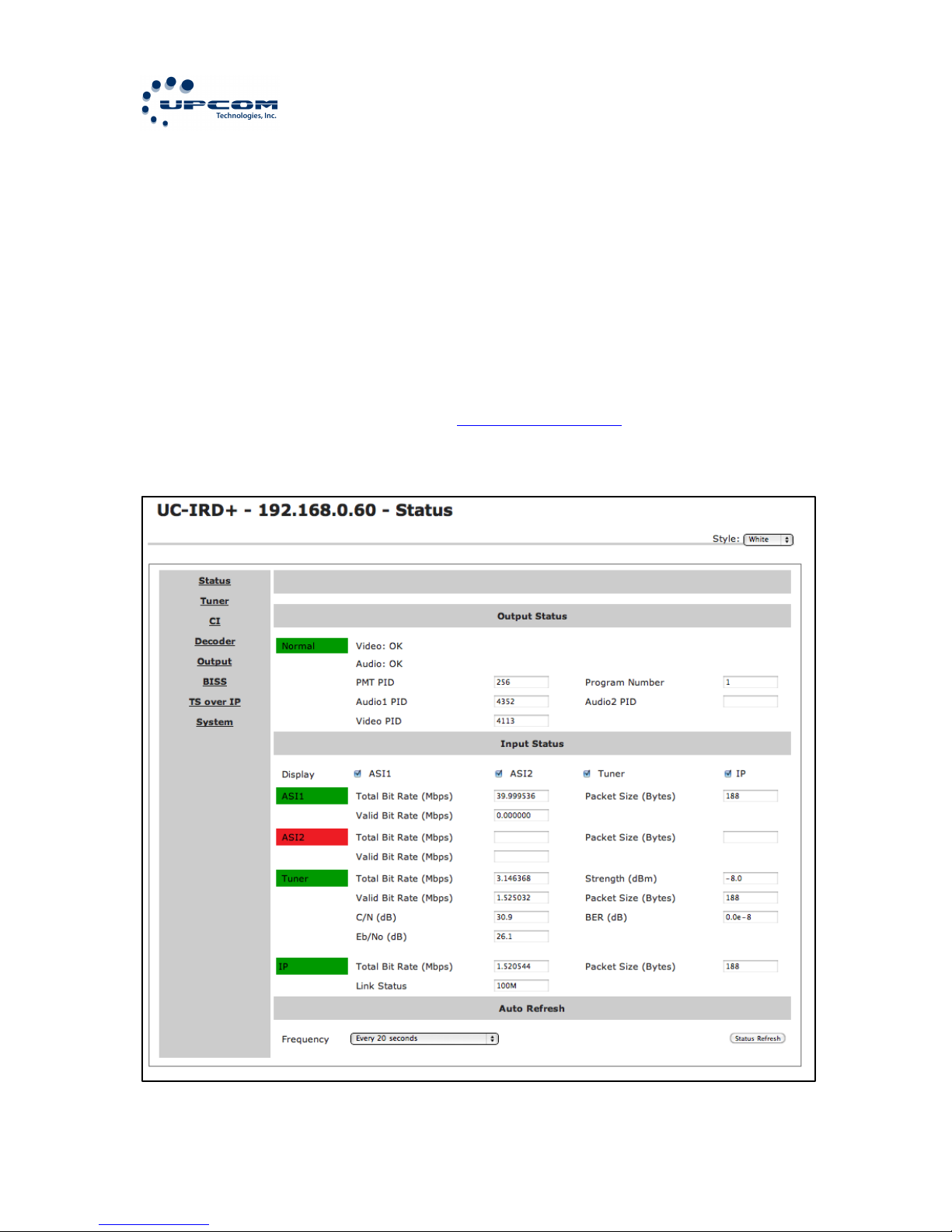
This is the Status page. It shows the status of your interfaces, and gives
information about the connections.
Setting$Up$Satellite$Inbound$(DVBJS2)$
This menu allows you to configure the Satellite Receiver. The parameters
must be known before starting. (Please contact your satellite provider if
you don’t have them)
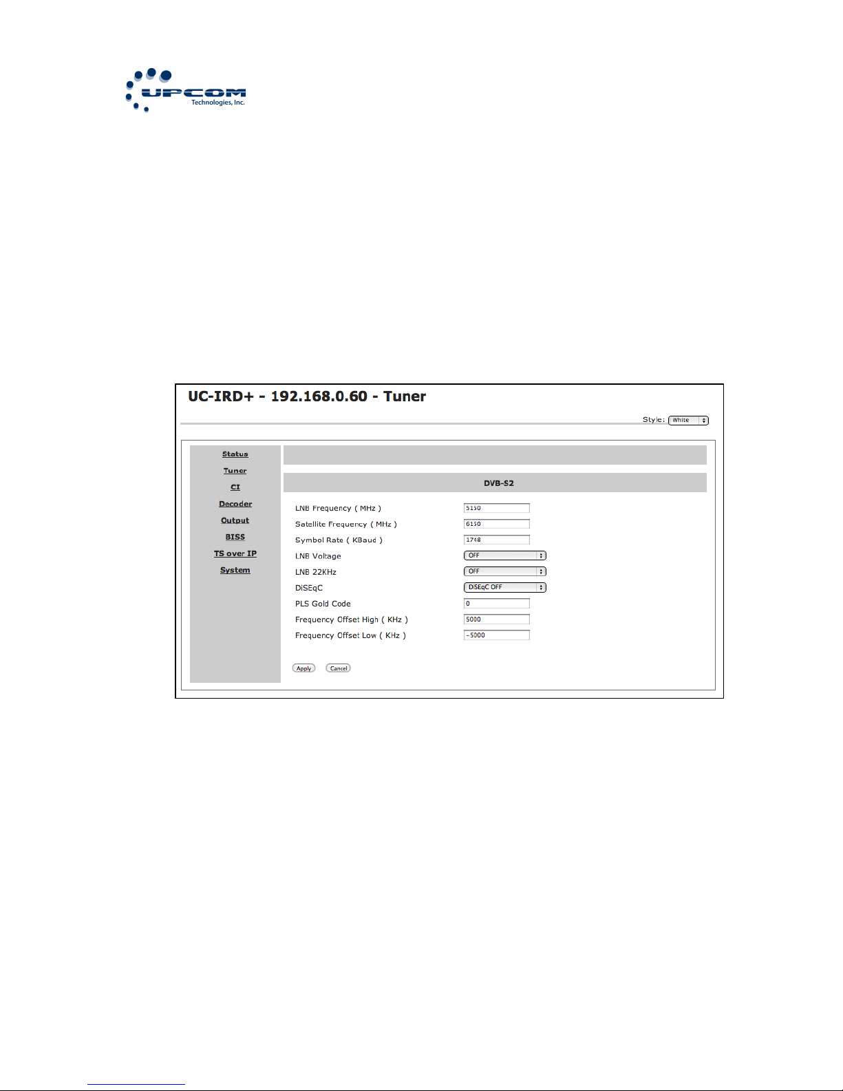
There are 9 options to setup on this menu:
LNB Frequency: The input LNB Frequency
Satellite Frequency: The input downstream frequency of the satellite
Symbol Rate: The input symbol rate for the stream
LNB Voltage: The voltage that will be sent through the F-Connector for
the LNB. Please select the correct option: Off, 13V, 18V.
LNB 22KHz: To activate the LNB 22KHz control signal. Options are: On,
Off.
DiSEqC: To activate or deactivate DiSEqC support. Options are: OFF/Port
A/Port B/Port C/Port D.
PLS Gold Code: 6 digit decimal Physical Layer Signalling
Page 25
UC-IRD+ MULTI-MODE RECEIVER / DECODER
25
Frequency Offset High (KHz):
Frequency Offset Low (KHz):
Setting$Up$the$Common$Interface$(DeJScrambling)$
This menu allows you to configure the Common Interface for inbound DeScrambling.
NOTE: Configure either the Satellite Inbound or Ethernet Inbound first
and make sure the input is locked to use it as your CI Source
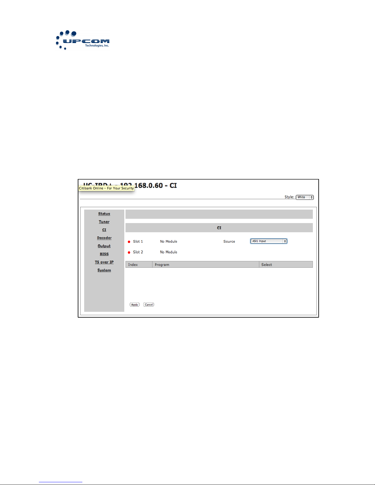
There are 3 options to setup on this menu.
CI Source: Select the input source for the CI module. The options are:
Tuner, ASI1, ASI2, IP input (If the TS/IP port is set to “IP in” on System > Optional Function).
Setup: Programs will be shown from the stream to be selected. Select the
program to be de-scrambled. Un-scrambled programs are marked as
“free”. Three different statuses could be set for each program:
Slot 1: Use the upper CAM to De-Scramble.
Slot 2: Use the lower CAM to De-Scramble.
Bypass: Do not De-Scramble the stream.
Page 26
UC-IRD+ MULTI-MODE RECEIVER / DECODER
26
The status will show up on the first row of the screen. Confirm the
selected setup before leaving the sub-menu.
The De-Scrambled stream will be ready to be used for the other functional
blocks like the Decoder, ASI1, ASI2, SDI, Mux and TS/IP Output.
Setting$Up$the$A/V$Decoder$
This menu allows you to configure the output of the UC-IRD+.
NOTE: All the other configurations must be done before like BISS, CI, and
Input configurations
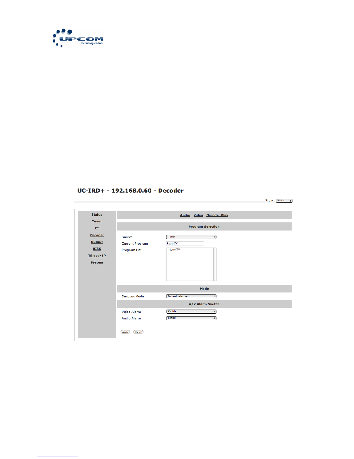
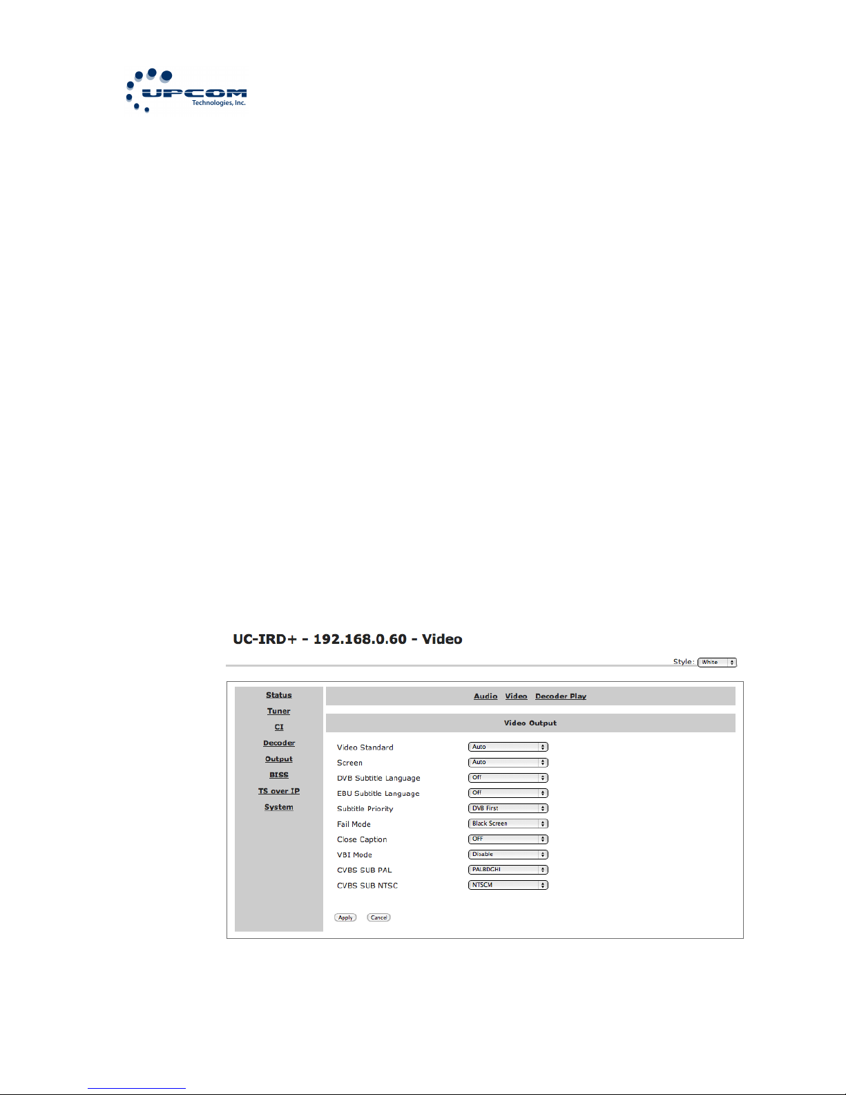
There are 7 options to setup on this menu.
Source: Select the source of the output. The output will be sent to
all the output ports on the back of the equipment with exception of
the ASI1 and ASI2 ports that can be configured independently.
There are 7 types of signal sources:
Page 27
UC-IRD+ MULTI-MODE RECEIVER / DECODER
27
Tuner: The input stream from the satellite tuner will be sent
to the outputs on the back of the device.
ASI1 Input: The input stream from the ASI1 IN Port will be
sent to the outputs on the back of the device.
ASI2 Input: The input stream from the ASI2 IN Port will be
sent to the outputs on the back of the device.
Mux TS: The input stream from the internal Mux functional
block will be sent to the outputs on the back of the device.
NOTE: The Mux must be enabled and configured for this
option to show up)
BISS De-Ecnrypted: The input stream from the BISS
functional block will be sent to the outputs on the back of
the device.
CI De-Encrypted: The input stream from the CI functional
block will be sent to the outputs on the back of the device.
IP: The input stream from the TS/IP Port will be sent to the
outputs on the back of the device. NOTE: If activated as
input on System->Optional Function.
Program: Select the program that the UC-IRD+ has detected from
the stream. It depends on the source you have selected before.
Video: This sub-menu allows you to define the video options
Page 28

UC-IRD+ MULTI-MODE RECEIVER / DECODER
28
Video: Select the video settings from the available options:
Auto, 576I 25, 480I 29.97, 576P 50, 480P 60, 720P 50, 720P
60, 1080I 25, 1080I 30.
Screen: Select the screen mode from the available options:
Auto, 4:3 Full, 4:3 Letterbox, 16:9 Full.
DVB Subtitle Lang: Select the language of the DVB subtitles
EBU Subtitle Lang: Select the language of the EBU subtitles
Subtitle Priority: Select which subtitle has higher priority
Fail Mode: Select the failure sent when the signal fails.
Available options are: Black Screen, No Sync or Still Picture
Closed Caption: Select to enable or disable the CC from the
stream
VBI Mode: Select to enable or disable the vertical blanking
interval mode
CVBS SUB PAL: Options are: PALBDGHI, PALN, PALN_C,
SECAM
CVBS SUB NTSC: Options are: NTSCM, NTSCM_J,
NTSCM_443, PALM.
Audio: This sub-menu allows you to define the audio options
Page 29
UC-IRD+ MULTI-MODE RECEIVER / DECODER
29
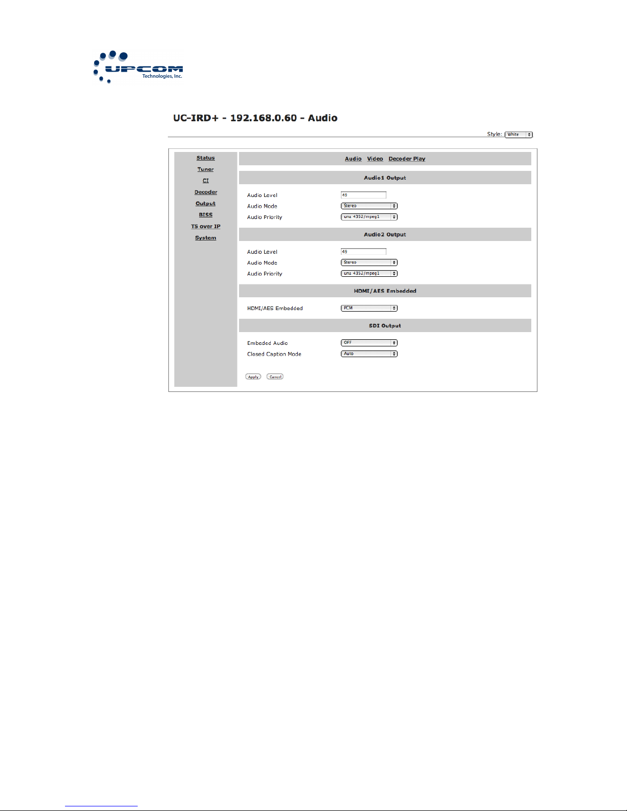
Audio 1 Level: Set the audio level from 0 to 99
Audio 1 Mode: Set the audio mode. The available options
are: Stereo, Left, Right, Mono.
Audio 1 Priority: Select the priority of the audio detected on
the stream.
Audio 2 Level: Set the audio level from 0 to 99
Audio 2 Mode: Set the audio mode. The available options
are: Stereo, Left, Right, Mono.
Audio 2 Priority: Select the priority of the audio detected on
the stream.
HDMI/AES Embedded: Select how to embed the audio on
HDMI. The possible options are: PCM or Compressed.
SDI Embedded Audio: Select to embed the audio on SDI.
The possible options are: On, Off.
Page 30
UC-IRD+ MULTI-MODE RECEIVER / DECODER
30
SDI Closed Caption Mode: Select the closed caption mode on
SDI
Status: Displays the status of the decode including PMT, PN, A/V,
Video and Audio
Mode: Select the program selection mode. The possible options
are: Manual Selection or First Service.
A/V Alarm Switch: This sub-menu allows you to activate the audio
and video alarms
Video alarm: Options are: Disable or Enable
Audio Alarm: Options are: Disable or Enable
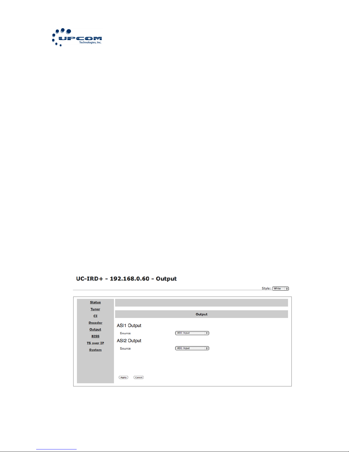
Sending$the$stream$to$the$ASI$outputs$
This will allow you to configure the ASI outputs on the back of the UCIRD+.
NOTE: All the other configurations must be done before like BISS, CI, and
Input configurations.
Page 31
UC-IRD+ MULTI-MODE RECEIVER / DECODER
31
There is only one option on to choose at this level, the source of the
stream. The possible options are: Tuner, IP, CD De-Encrypted, ASI Input,
BISS De-Encrypted, Mux TS
Setting$up$BISS$$
This will allow you to configure the BISS on the UC-IRD+.
NOTE: All the other configurations must be done before like CI, and Input
configurations. You must get the BISS settings from your provider.
Page 32

UC-IRD+ MULTI-MODE RECEIVER / DECODER
32
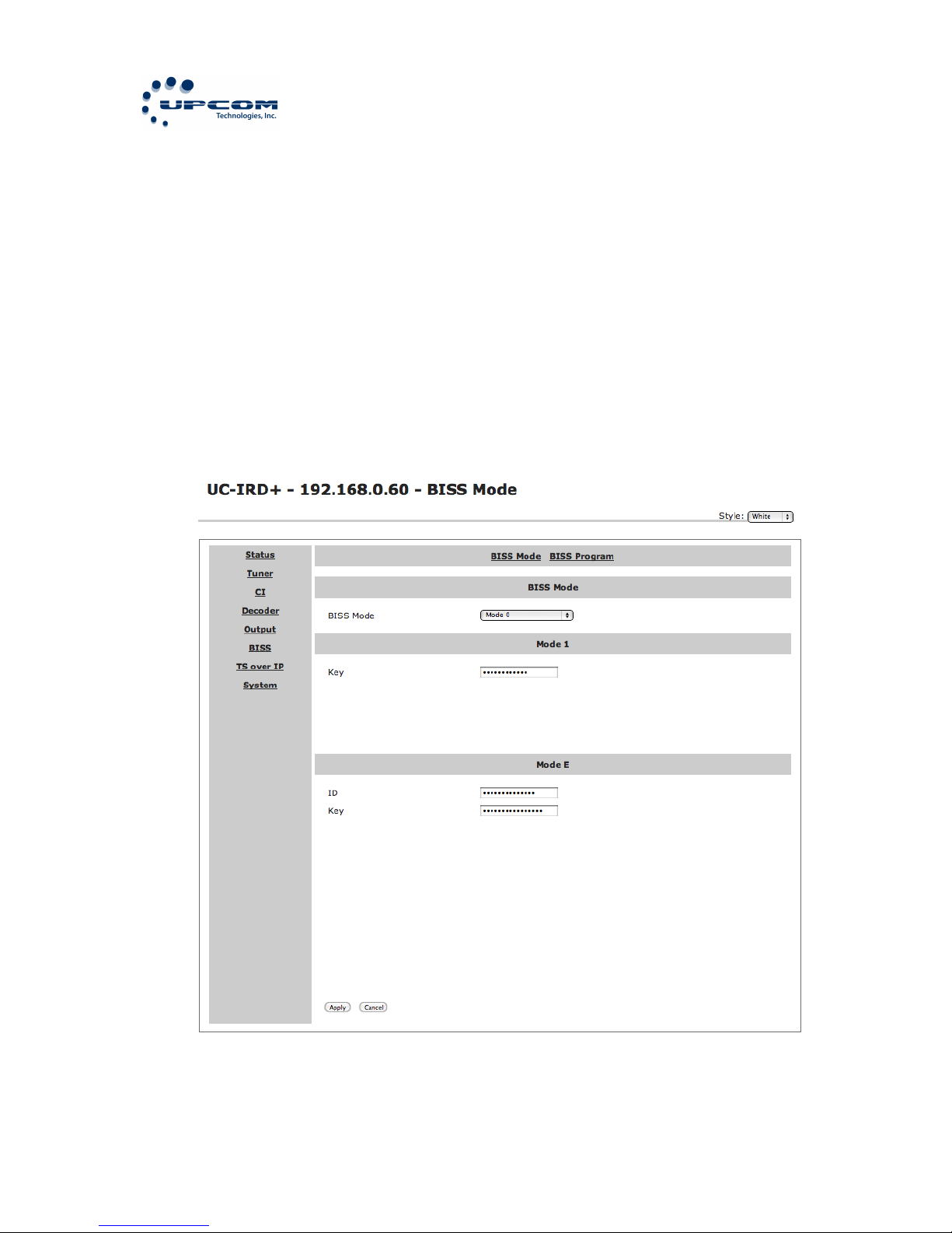
There are different options to setup on this menu.
BISS Mode: Select the correct BISS Mode to use with the TS. The possible
options are: Mode 0, Mode 1, Mode E
Depending on the selection of BISS Mode you will have different options
to choose:
If you choose Mode 0 the only available option is the source.
If you choose Mode 1 you will need to enter the BISS Mode 1 Key, then
you must choose the source and the program to De-Scramble.
If you choose Mode E you must enter the ID & Key, then choose the
source and finally select the program. The options will change depending
on the selections you make.
A few seconds after the correct configuration is selected the A/V signals
will be sent to the connectors on the back of the device.
Page 33
UC-IRD+ MULTI-MODE RECEIVER / DECODER
33
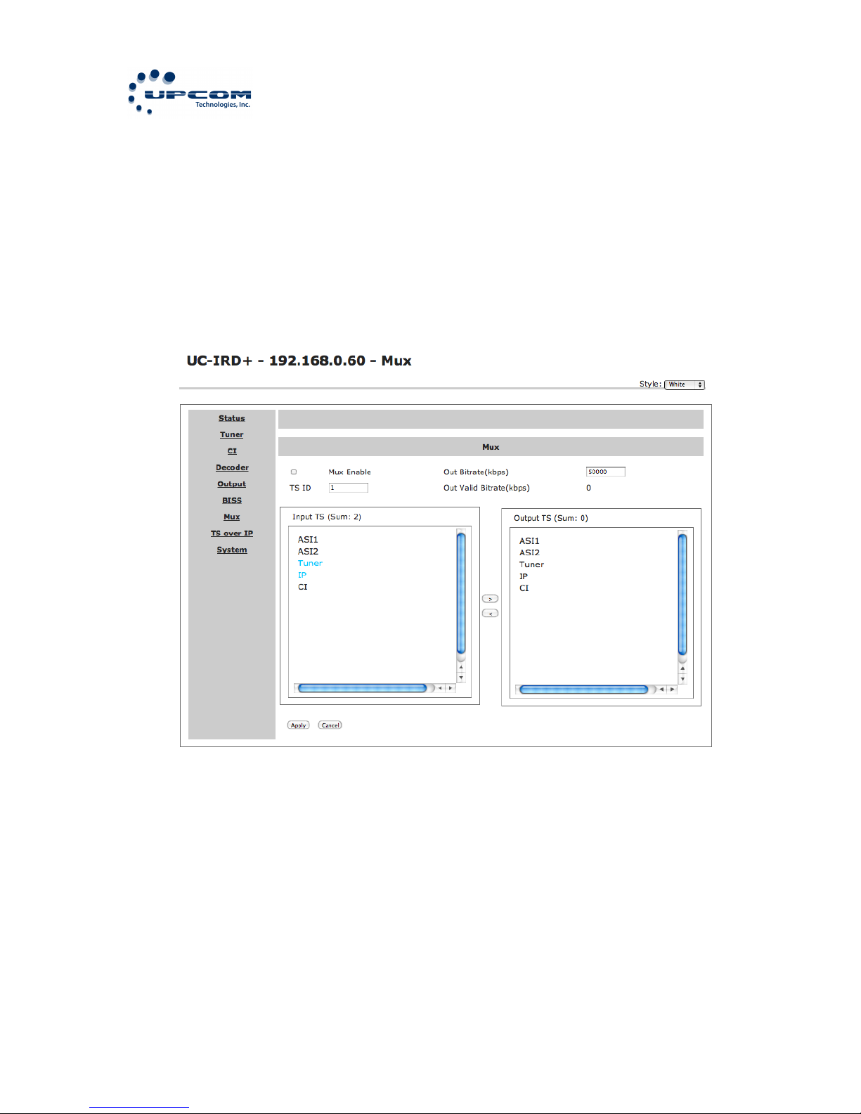
Configuring$the$internal$MUX$
This will allow you to configure the internal MUX on the UC-IRD+.
NOTE: This option only will be available if it is enabled on System>Optional Function. All the other configurations must be done before like
BISS, CI, and Input configurations.
There are different options to setup on this menu.
Mux Switch: Select whether the internal multiplexer is On or Off
Bit Rate: Set the stream bit rate. Be aware that it should be within the
limits of the physical medium you’re using otherwise overflows can occur.
Output Bit Rate
TS Id: Set the TS ID to mark the multiplexed stream. The default value is
1.
Page 34
UC-IRD+ MULTI-MODE RECEIVER / DECODER
34
Program List sub-menu: This sub-menu allows you to create a list of
programs to “pass” to the output. The programs could come from ASI
inputs, Tuner, TS/IP or the Internal CI De-Encryption block. Using the
“Mux List” sub menu select the programs to be multiplexed, all the
selected programs are labeled “Pass”, the un-selected programs are
labeled “Forbid”. Use the ENTER pushbutton to select or un-select the
programs. When you finish your selection press the EXIT pushbutton to
exit the sub-menu. A confirmation message will ask to “Confirm
changed?”, press the ENTER pushbutton to save your changes or EXIT to
leave without saving.
After a few seconds the multiplexed TS will be generated and can be used.
Configuring$Ethernet$Streaming$
This will allow you to configure the TS/IP port on the UC-IRD+ as a
Stream Source for another device.
NOTE: This option only will be available if it is enabled on System>Optional Function. All the other configurations must be done before like
BISS, CI, and Input configurations.
There are different options to setup on this menu.
Page 35

UC-IRD+ MULTI-MODE RECEIVER / DECODER
35
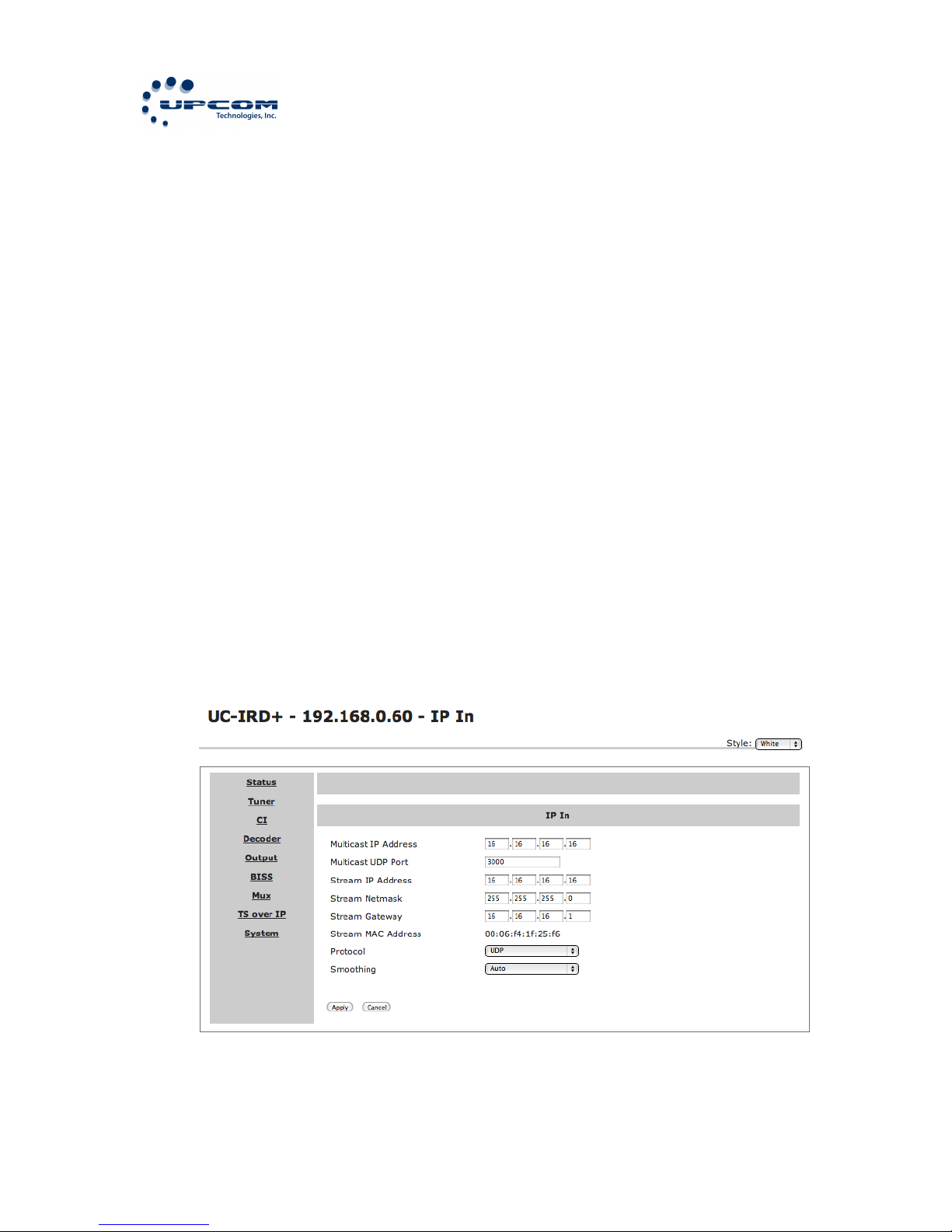
Stream IP Address: Enter the IP address assigned to your equipment
TS/IP output.
Stream Netmask: Enter the network netmask for the IP address assigned
to your equipment TS/IP output.
Stream Gateway: Enter the gateway address for the IP address assigned
to your equipment TS/IP output.
Stream MAC Address: The Factory-Set MAC address assigned to the TS/IP
port.
Gateway MAC Address: The MAC address of the configured Gateway.
Protocol: Set the protocol for multicast. The possible options are UDP or
RTP
TS Pkts per UDP: Set the number of the TS packets encapsulated in one
UDP packet. Valid range is from 1 to 7
Time to Live: set the number of router hops over which the TS over IP
can be delivered. The valid range is from 1 to 5.
Type of Service: Select the type of service. The possible options are:
Normal, Min Monetary Cost, Max Reliability, Max Throughput or Min Delay.
Source: Select de source of the stream to be encapsulated over IP. There
are 5 possible options
1. ASI1 Input
2. ASI2 Input
3. CI De-Encrypted
4. TUNER
5. Mux TS (Only available if it is enabled)
6. BISS De-Encrypted
Mode: Select the mode of IP Streaming. The valid options are DVB or
IPTV
DVB Mode: The transport stream from the source will be directly
sent as an IP stream. The IP stream will include all the programs
and will be sent to the specified multicast or unicast IP Address.
IPTV Mode: The transport stream from the source is de-Muxed into
individual programs, each of one is packed into a different IP
stream. Each IP stream carries only one program. There is a
maximum of 6 IPTV channels allowed to be set.
Uni/Multicast Setup: This sub-menu will allow you to set the Unicast or
Multicast settings. It offers different options depending on the mode
selected.
Page 36

UC-IRD+ MULTI-MODE RECEIVER / DECODER
36
For$DVB$Mode:$
Multicast IP: set the IP address of the TS over IP. It can be
configured as a Multicast or Unicast stream.
To use multicast mode set the IP address within the Multicast IP
range 224.0.0.0 to 239.255.255.255 as defined by RFC 5771.
To use Unicast mode use any valid IP address that is not in the
range 224.0.0.0 to 239.255.255.255. When the IP address is set to
an IP address outside of this range the stream will be Unicast even
though the display shows “Multicast IP”. In Unicast mode the IP
address that is used is the one of the destination.
Multicast UDP Port: Enter the UDP port number of the TS over IP.
For$IPTV$Mode:$
Max Channels (<=6): Set the number of IPTV channels. The valid
range is from 0 to 6.
Once the number of channels is set, there will be a sub-menu for
each channel. Each channel sub-menu has 4 options:
Channel x: where “x” is the number of the channel
x-Switch: Set the channel On or Off.
x-Uni/Multicast IP IP: set the IP address of the TS over IP. It
can be configured as a Multicast or Unicast stream.
To use multicast mode set the IP address within the
Multicast IP range 224.0.0.0 to 239.255.255.255 as defined
by RFC 5771.
To use Unicast mode use any valid IP address that is not in
the range 224.0.0.0 to 239.255.255.255. When the IP
address is set to an IP address outside of this range the
stream will be Unicast even though the display shows
“Multicast IP”. In Unicast mode the IP address that is used is
the one of the destination
Page 37
UC-IRD+ MULTI-MODE RECEIVER / DECODER
37
x-Uni/Multicast Port: Set the UDP port number for the TS
over IP
x-Program: Select the program to use from the previously
selected source. Encrypted programs are labeled with a “$”
sign.
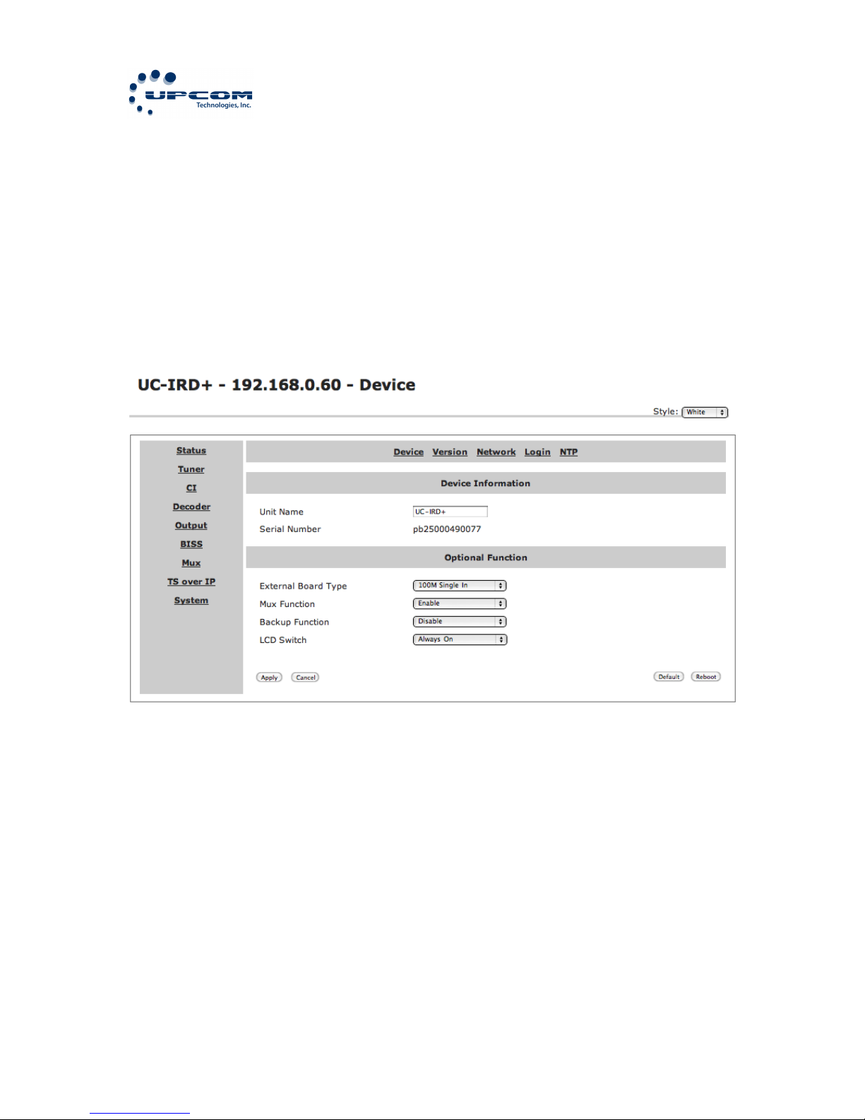
Device$Information$
Page 38
UC-IRD+ MULTI-MODE RECEIVER / DECODER
38
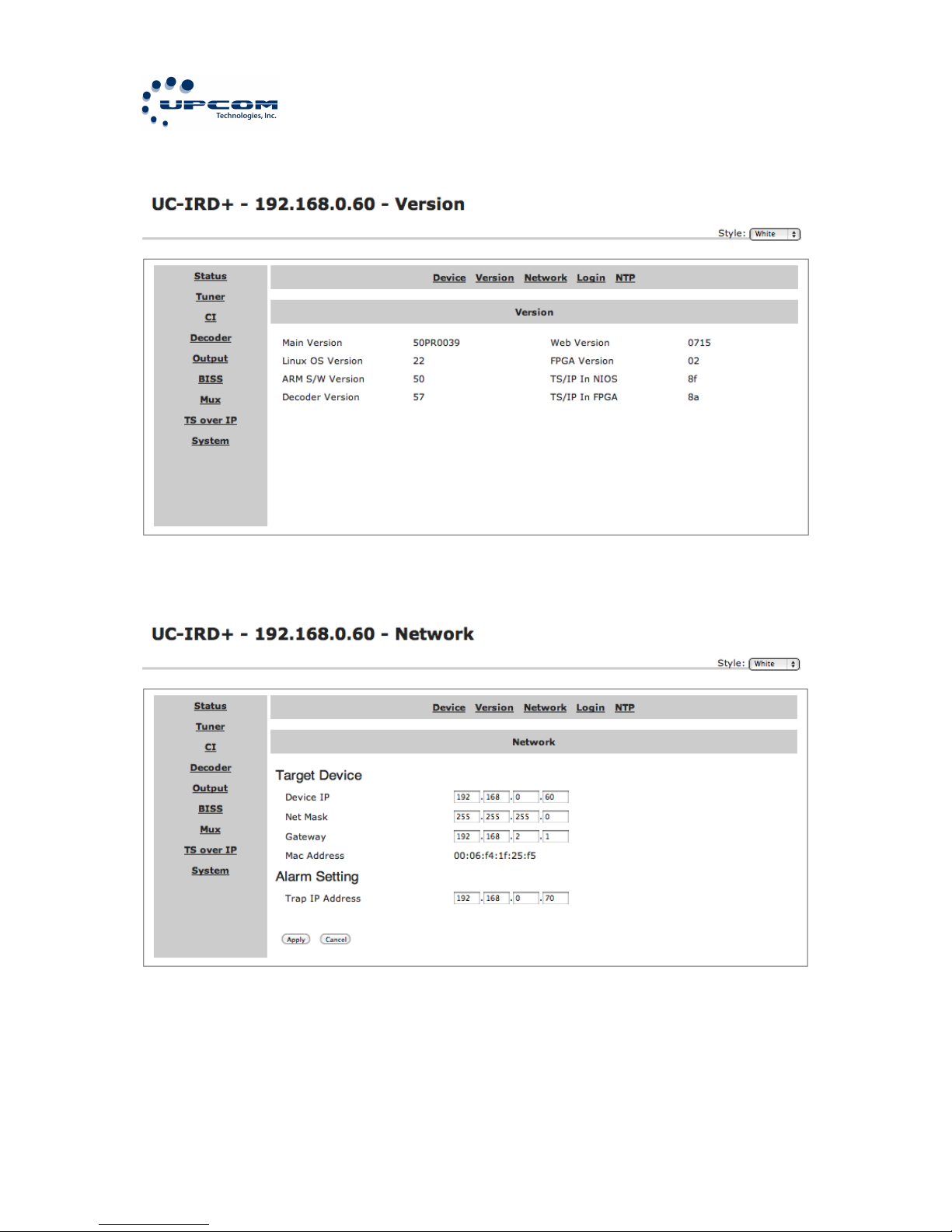
Software$Version$
Network$Configuration$
Page 39
UC-IRD+ MULTI-MODE RECEIVER / DECODER
39
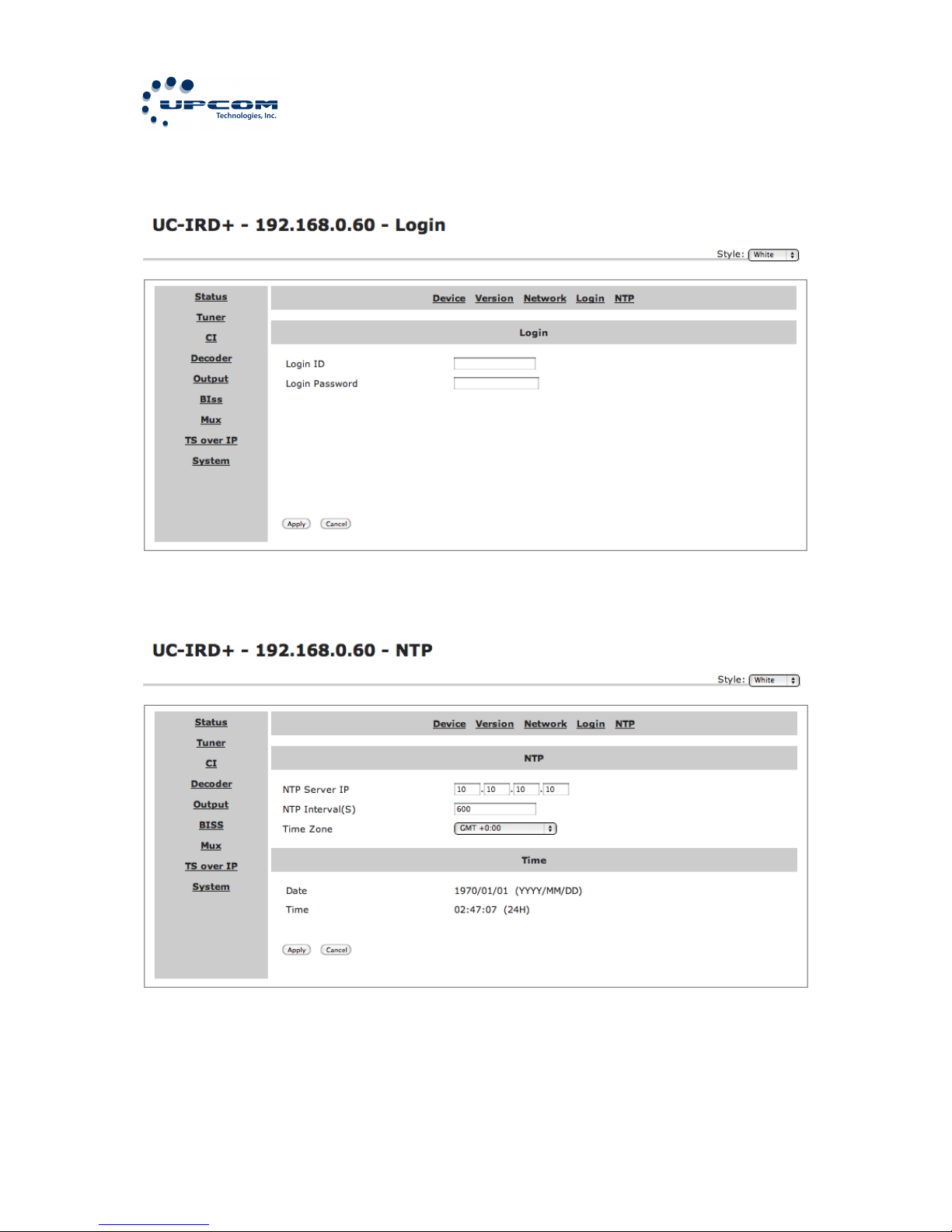
HTTP$Login$
Network$Time$Protocol$Configuration$
Page 40
UC-IRD+ MULTI-MODE RECEIVER / DECODER
40
ANNEX%A%
IRD%MENU%STRUCTURE%
LNB Frequency
Satellite Frequency
Symbol Rate
LNB Voltage
LNB 22KHz
DiSEqC
PLS Gold Code
CI Source
Setup
CAM name
Source
Program
Video
Audio
Status
Mode
A/V Alarm Switch
Embed Audios
Closed Caption Mode
BISS Mode
Mode 1 Key Enter
BISS Source
Program Source
Stream IP Address
Stream Netmask
Stream Gateway
Stream Mac Address
Gateway Mac Address
Protocol
TS Pkts Per UDP
Time To Live
Type of Service
Source
Mode
Uni/Multicast Setup
IP Address
Network Mask
Gateway
Login ID
Login Password
External Board Type
Mux Function
LCD Switch
(Depends of settings on System -> Optional Function)
Stream IP Address
Stream Netmask
Stream Gateway
Stream Mac Address
Multicast UDP Port
Multicast IP Address
Protocol
Output Smoothing
Inputs
Outputs
System
Main Menu
Status
RSSI
DVB-S2
Ethernet
CI
Decoder
ASI 1
ASI 2
SDI
BISS
Ethernet
Local Setup
Trap IP Address
Unit Name
HTTP Login
Properties
Factory Settings
Optional Function
Machine Type
Mux
Mux Switch
Bit Rate
Output Bit Rate
TS Id
Program
*
*
*
*
Page 41
UC-IRD+ MULTI-MODE RECEIVER / DECODER
41
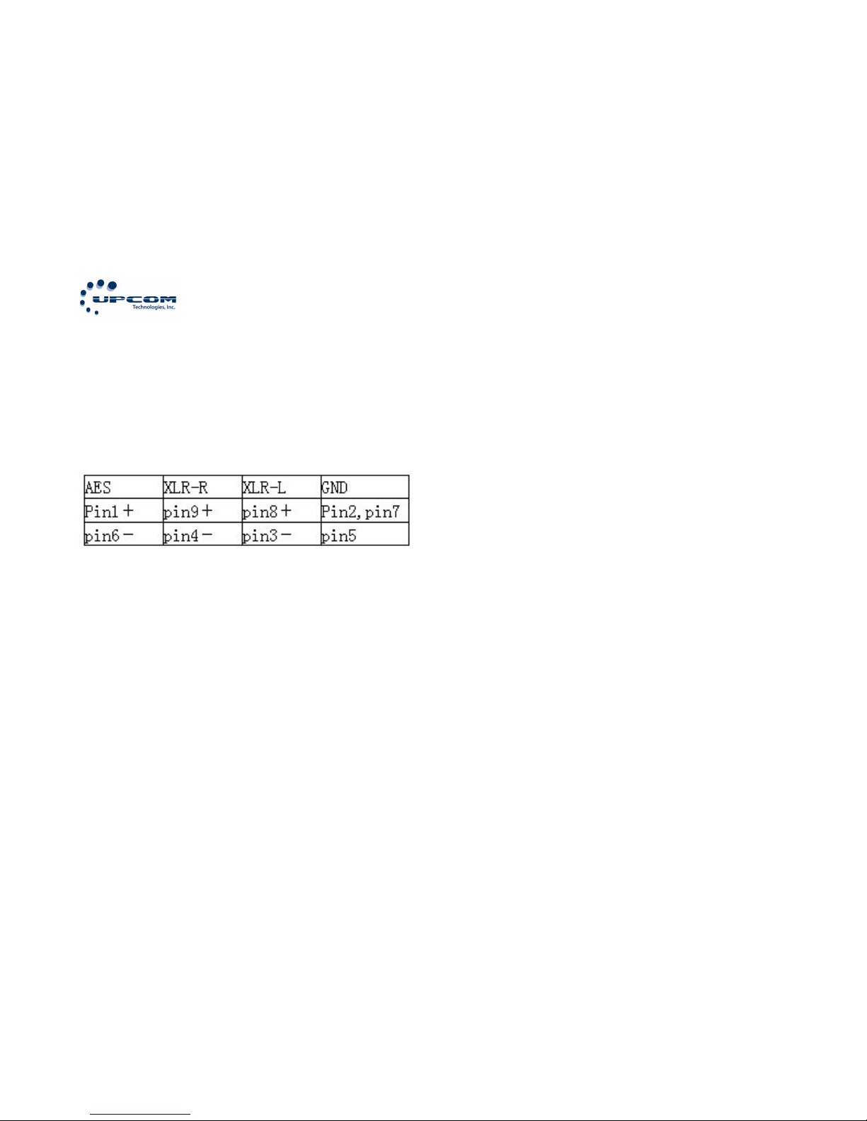
ANNEX%B%
AES%Balanced%Audio%Pinout%
 Loading...