

Page 1

Read instructions carefully before use and follow them for correct use.
It is recommended that training be given on the proper use of this product.
Retain this manual for future reference.
Please include it with the product in the event of transfer to new users.
Additional copies are available upon request.
Unwin House • The Horseshoe • Coat Road • Martock •
Somerset • TA12 6EY • UK
Tel: +44 (0)1935 827740 • Fax: +44 (0)1935 827760
Email: sales@unwinsafety.com
Website: www.unwinsafety.com
UI2053B
OR01, OR02, OR09, OR10, OR11
ORS01, ORS02
Page 2

A. Limitations of use
B. General Guidance
C. Before Using The Rear Tie-downs
D. Fitting OR01 and OR02
E. Fitting ORS01
F. Fitting OR09 and OR10
G. Fitting OR11
H. Fitting ORS02
I. Equipment Storage & Maintenance
J. Warranty
K. Product Range
CONTENTS
A. LIMITATIONS OF USE
1. These Unwin Rear Webbing tie-downs are designed to secure a wheelchair when facing forward in a
vehicle and must be used as instructed for forward-facing seating. The rear webbing tie-down are
designed to secure wheelchair weights up to 120kg with the exception of OR11 which is designed to
secure a wheelchair weight of up to 140kg.
2. OR01, OR02, ORS01 are wheelchair tie-down only and will require an additional occupant restraint.
3. OR09, OR10, OR11, ORS02 includes an occupant restraint for the wheelchair user.
4. In addition to the details given in these Instructions, users of Unwin webbing tie-down must refer to
the wheelchair manufacturer’s ‘Instructions For Use in Transport’ for full details of tie-down
attachment points on the wheelchair, plus any other specic instructions relating to use in transport.
5. Wheelchair users and their carers must make sure that their wheelchair is recommended for use in
transport, including any ‘add-on’ components such as power tilt or recline options.
6. The development of Unwin wheelchair tie-downs and occupant restraints is a continuous process.
Applications are added on a regular basis. For more detail contact Unwin or look on the Unwin
website.
B. GENERAL GUIDANCE
1. Wheelchair Accessories that have not been approved by the Wheelchair Manufacturer must be
removed from the wheelchair and secured in the vehicle during transport to reduce the
potential for injury. Refer to ‘Instructions For Use in Transport’ provided with the
wheelchair or contact wheelchair manufacturer for further guidance.
2. These rear tie-downs comply with all applicable requirements of ISO 10542 including a
48-km/h, 20g frontal impact test using a forward facing 85kg surrogate wheelchair and an ATD
(test dummy) with a mass of 76.3kg. The test dummy was restrained by both the pelvic and
upper-torso restraint as described in latter detail, use of a pelvic only belt may compromise
the performance of the WTORS system and should avoided.
3. If the installation is to be used with an occupant head rest anchored to the vehicle, then a
vehicle-anchored back rest must be provided to minimise rearward deection of the
wheelchair seatback, preventing neck injury.
4. Regular inspection of all parts is recommended and the equipment should be used only if all
components are in good condition. Warning: protect webbing from contacting sharp edges
and corners. Replace equipment if the webbing does becomes cut, contaminated or frayed.
Page 3

6. Do not attempt to modify the equipment. For further advice on the installation and use of these
WTORS please contact Unwin. Please read this manual fully before use.
7. Avoid contact with corrosive liquids. Care should be taken to prevent contamination of the webbing
with polishes, oils and chemicals.
8. These WTORS should be installed by an experienced technician/ vehicle converter. Anchorages
should not be installed into unsound materials such as corroded metal, wood, plastic and bre glass
panels without additional and suitable reinforcement.
9. The equipment has been tested in a conguration similar to that recommended by Unwin , and any
deviation from the recommendations here is the responsibility of the installer.
C. BEFORE USING THE REAR TIE-DOWNS
1. Ensure that the wheelchair is correctly maintained and that the
settings of any adjustable parts are made according to ‘Instruction
for Use in Transport’.
2. Whenever possible remove any items of luggage etc that may be
attached to the wheelchair and secure or store separately during
transport in order to reduce the potential for injury to other
passengers travelling in the vehicle.
3. Extra care must be exercised when using vehicle boarding aids
such as passenger lifts or ramps during the loading process. Refer
to ‘Instructions For Use’ for information on safe slopes.
4. Position the wheelchair facing forward - centrally in the
designated region of the vehicle. Ensure the wheelchair brakes are
applied.
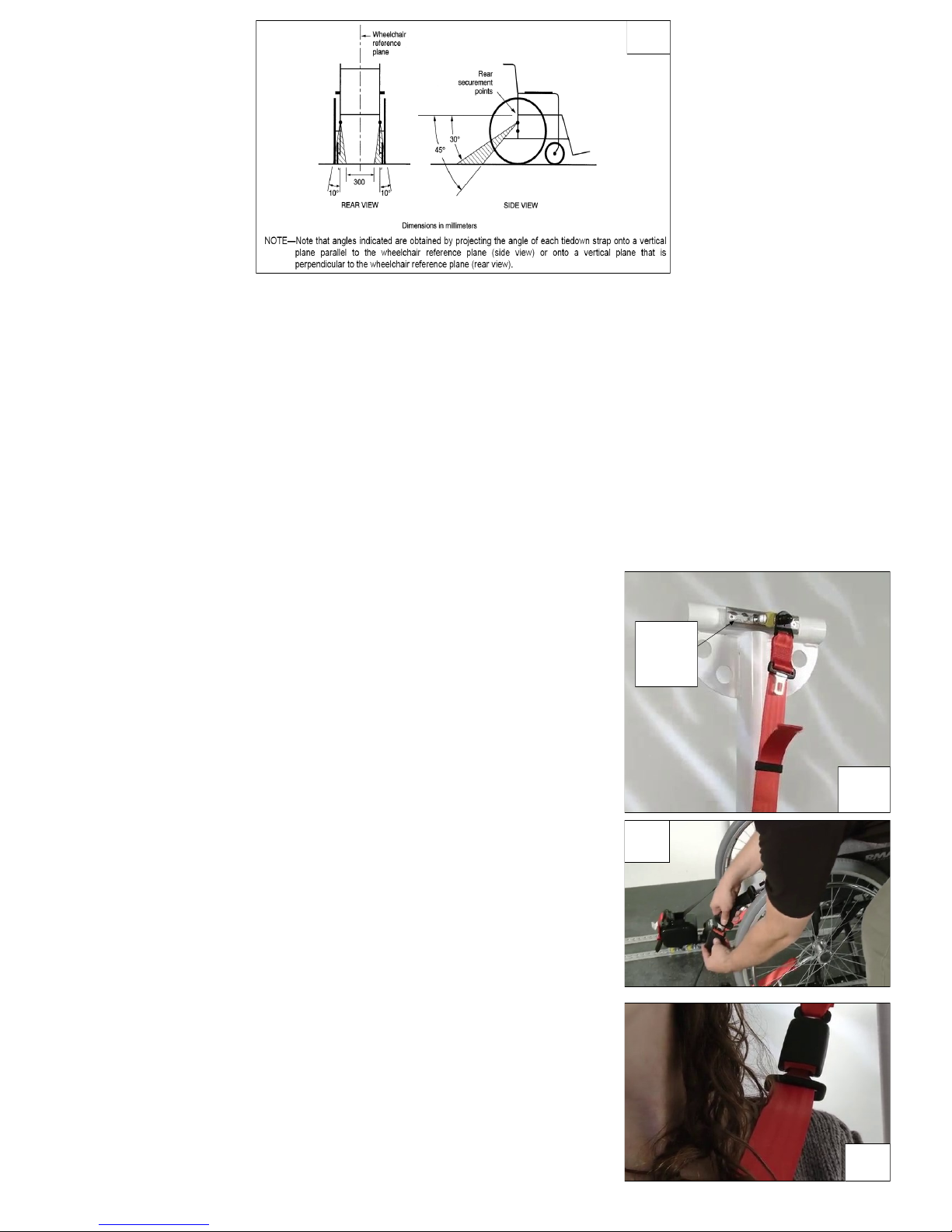
5. To minimise the potential for head injuries in an impact, allow a
clear space of at least 400 mm behind and 650 mm, (FCZ, front
clear zone), in front of the head of the wheelchair user. (Fig 1.).
The shoulder belt anchorage must be roof or side-wall anchored at a height level such that the belt
webbing passes over the midpoint of the occupant shoulder and at a height that is at or just above the
level of the occupants shoulders so as not to impose downward loads on the spine.
6. A height provision (HHT) ranging from 1000mm to 1550mm should be made, depending on the size
of the passenger. There should also be 200 mm of clear space either side of the wheelchair centre
line. If these clear space dimensions cannot be provided then any structure protruding into this space
should be adequately padded and comply with impact performance requirements of ECE Regulation
21 ‘FMVSS 201’. All vehicle padding should comply with the ammability requirements of ECE
Regulation 118 ‘FMVSS 302’.
7. Note: seated head height (HHT) ranges from as low as 1000mm for a 6-year old child to 1550mm for a
tall adult.
8. Wheelchair users, their carers and family are advised to check vehicle specications to ensure that
sucient oor space is available to accommodate the wheelchair and tie-down system. These
distances are based upon the desire to maintain clear zones for potential head excursions of
occupants provided with both upper and lower torso restraints.
9. Users of heavy powered wheelchairs are also advised to check vehicle carrying capacity. If in doubt
consult the vehicle supplier for further details.
10. Any airbag, as tted to the vehicle, shall only be used as a supplementary occupant restraint if
designed to be used in combination with the WTORS kit.
11. Installers of this kit should take note of any vehicle airbag position when planning the installation.
Airbags can cause serious injury if a wheelchair-seated occupant is seated too close to an airbag
position. If in doubt contact the vehicle manufacturer or your National Automotive Regulatory Body
for advice.
1
Page 4

D. FITTING OR01, OR02
OR01 OR02
1. The rail will have been installed in the vehicle, in accordance with our
own and the vehicle converters instruction. A front wheelchair tie-down
should be secured rst, before any rear restraints are tted.
2. To attach the above rear wheelchair tie-down, select each half of the tie
-down so that the karabiner gate faces outboard from the wheelchair,
(Fig 2). If using the tongue and buckle wheelchair attachment, either
strap can be selected for either side as they are not handed.
3. Attach each tie-down into the oor rail by aligning the ATF (aluminium
track tting) feet with the cut-out sections of the rail, (Fig 3). Note: the
yellow plungers must face toward the rear of the vehicle. Press on the
ribbed part of the ATF, (Fig 3) and push rmly down and towards the
wheelchair until the yellow plunger drops and locks into the rail. Ensure
that each ATF is sited opposite each other.
4. Remove the webbing from the Velcro patch and release
the over-centre buckle.
5. Attach the Karabiner or the tongue and buckle xing to
the wheelchair main frame to create an angle of about 3045° within the rear view zone, (Fig 5). (Some chairs will
indicate this tie-down position). If using tongue and buckle
press the red buckle button(s) to release the webbed
tongue(s), extend and pass around each of the wheelchair
frame tie-down points, reconnect the tongue back into
the buckle.
6. Pull the webbing through the over-centre buckle until it is
tight. With the free hand begin to close the buckle, once
the webbing is retained, fully close the buckle using both
hands, (Fig 4). Re-secure the Velcro to prevent the loose
end from becoming a tripping hazard.
7. An occupant restraint should now be tted.
3
4
2
Page 5

1. The Solo oor anchors will have been installed in the vehicle, in
accordance with our own and the vehicle converters instruction.
A front wheelchair tie-down should be secured rst, before any
rear restraints are tted.
2. Select each half of the tie-down so that the karabiner gate faces
outboard from the wheelchair, (Fig 2).
3. Attach one of the rear tie-down cleats, onto a rear Solo oor anchor
by aligning the button within the cleat to the slot on the oor
anchor, (Fig 6), slide the cleat fully home, (raising the anchor from
its housing if using the retractable Solar oor anchor), and rotate
the cleat through 90°, (Fig 7), to align the karabiners with the
wheelchair frame. Install the second rear tie-down cleat to its
anchor in the same way.
6. Remove the webbing from the Velcro patch and release the over-
centre buckle.
7. Attach the Karabiner to the wheelchair main frame to create an
angle of about 30- 45° within the rear view zone (Fig 5). (Some
chairs will indicate this tie down position).
8. Pull the webbing through the over-centre buckle until it is tight.
With the free hand begin to close the buckle, once the webbing is
retained, fully close the buckle using both hands, (Fig 8). Re-secure
the Velcro to prevent the loose end from becoming a tripping
hazard.
9. An occupant restraint should now be tted.
ORS01
Patent GB2355437, US6869260, AU775895
PROTRUSION
INDENT
7
6
E. FITTING ORS01
REMOVING THE TIE-DOWNS:
1. Ensure the wheelchair brakes are applied.
2. Release the webbing tension in each rear side by
pressing in the silver release on the over centre
buckles and detach the karabiner(s) or tongue and
buckle arrangement from the wheelchair frame.
3. Lift the yellow plunger fully and slide back away from
the wheelchair to align the ATF feet with the rail cut
outs, lift away from the rail. Close the over centre
buckle and return the webbing end to the Velcro
patch.
4. The front straps should now be removed, please refer to the appropriate user instructions.
5
8
Page 6

F. FITTING OR09 and OR10
Fitting the Combined Systems - Wheelchair Tie-down:
1. The rail will have been installed in the vehicle, in accordance
with our own and the vehicle converters instruction. A front
wheelchair tie-down should be secured rst, before any rear
combined restraints are tted.
2. Place the combined rear webbing restraint into the rail behind
the wheelchair. It is acceptable to use the restraint either for
left hand or right hand use. The double inertia reel should be
tted to the rail adjacent to the 3rd point anchorage (Fig 9).
3. Lift the double locating plunger and slide into the rail, by
pushing the bar slightly forward or backward until the plunger
drops and locks into place (Fig 9). Repeat with other bar.
IMPORTANT: Check that both bars are positioned exactly
opposite each other, they are secured and the plungers are
fully dropped.
4. Remove the webbing from the Velcro patch and release the
over-centre buckle.
5. Attach the Karabiner or the tongue and buckle xing to the
wheelchair main frame to create an angle of about 30-45°
within the rear view zone, (Fig 11). (Some chairs will indicate
this tie-down position). If using tongue and buckle press the red
buckle button(s) to release the webbed tongue(s), extend and pass around each of the wheelchair
frame tie-down points, reconnect the tongue back into the buckle.
6. Pull the webbing through the over-centre buckle until it is tight. With the free hand begin to close the
buckle, once the webbing is retained, fully close the buckle using both hands, (Fig 10). Re-secure the
Velcro to prevent the loose end from becoming a tripping hazard.
7. The occupant restraint should now be tted.
OR09 OR10
10
Plunger
Double Inertia
3rd Point
Anchorage
9
To remove the rear tie-down:
1. Ensure the wheelchair’s brakes are applied.
2. Release the over-centre buckle on the rear strap, loosen the webbing and remove the
karabiner from the wheelchair frame. Close the over-centre buckle and replace webbing to
Velcro.
3. Turn the cleat back through 90° to release and slide it o of the oor anchor point. Repeat
operation with opposite strap.
4. The front straps should now be removed, please refer to the appropriate user instructions.
Page 7
Unwin recommends the use of a 3 point occupant restraint system to provide greater protection
in case of an impact. However we also recognise that some vehicle layout/designs or specic
postural or medical conditions do not allow that style of seatbelts to be used easily.
This system is not ISO 10542 compliant if used in 2 point conguration.
Before tting the occupant restraint, ensure that the reversible stalk orange button is facing
outside in relation to the wheelchair. If the reversible stalk orange button faces inside, turn the
stalk 180º to sit in the right position.
In accordance with International regulations, standard Unwin occupant restraints are designed
to be used for passengers weighing 22kg or above. If the passenger weighs less than 22kg, Unwin
recommend that a suitable, and appropriately tested child restraint seat is used. This may involve a secondary seat belt restraint as recommended by the original seat
manufacturer.
Fitting the Combined System - 3 Point Occupant Restraint
1. Position the third point xing into the cant rail (Fig 12) so that it is
vertically above the inertia reel casing xed onto the oor xing.
Unfasten the tongue and buckle.
2. Pull the black webbing upwards and unfasten the tongue from the
red webbing buckle.
3. Position the black webbing to form the lap belt and insert the
tongue into the buckle stalk (Fig 13).
4. Ensure that the lap belt lays low on the pelvis of the occupant,
running as close as possible over the hips on both sides.
5. Remove the black plastic cover on the red shoulder belt tongue and
t into the third point xing.
6. Position the red webbing to form the shoulder belt and insert the
buckle into the tongue.
7. Adjust the height of the shoulder belt to clear the occupant’s
shoulder by approximately 25mm (1 inch) Fig 14.
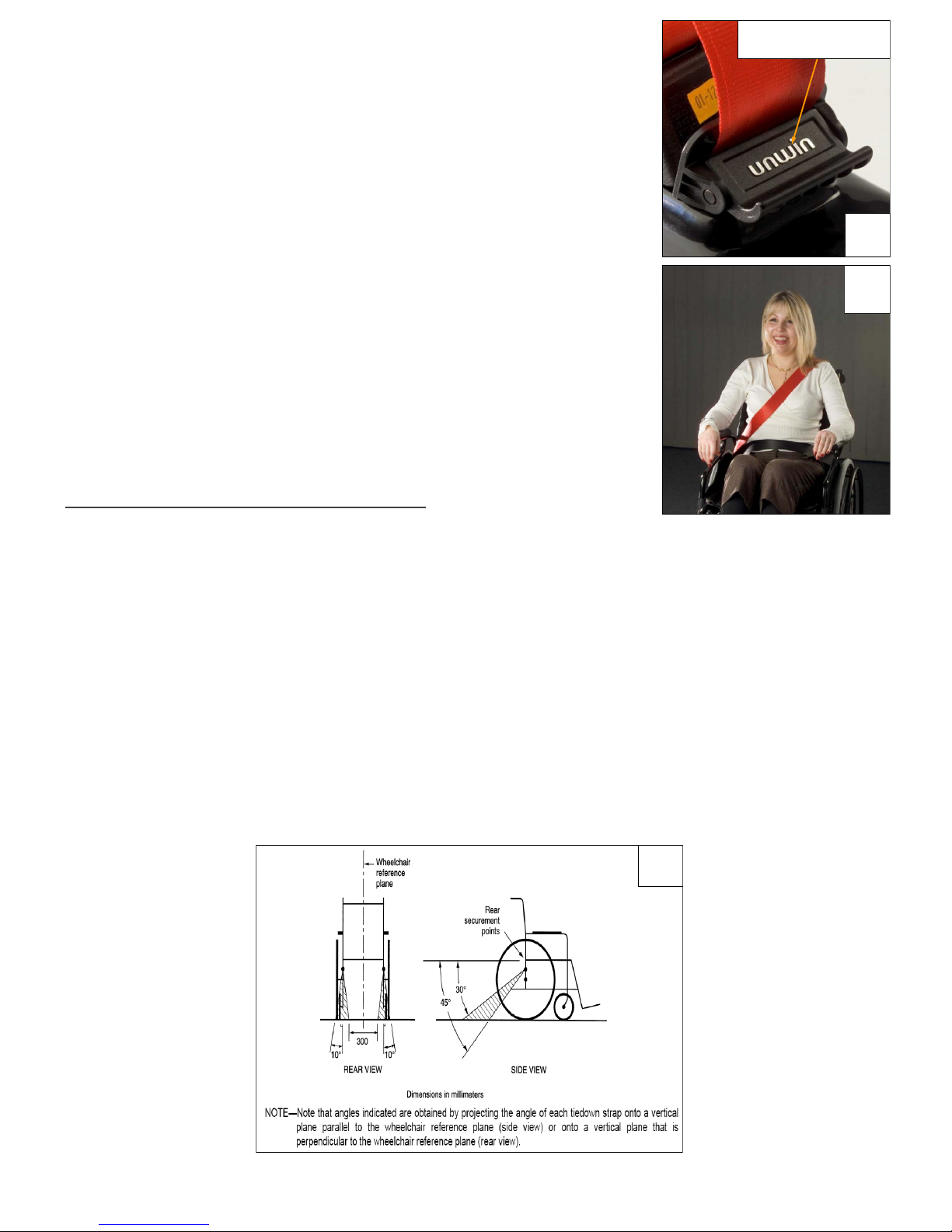
8. The lap belt anchor points should be positioned to achieve belt
angles of 30° or more to the horizontal and preferably between 45°
and 75° in order to t low across the pelvis reducing the possibility
of the belt loading the abdomen (Fig 11). The pelvic restraint is
designed to bear upon the bony structure of the body and should be
worn low across the front of the pelvis with any junctions between
the pelvic and shoulder restraints located near the wearers hips.
Important: For wheelchairs with xed armrest,
please contact Unwin.
11
Cant
Rail
12
13
14
Page 8
Fitting the Combined Systems - 2Point Occupant Restraint
1. Ensure the Comfort Clip is released (Fig 15) and press the buckle to
release the lap belt.
2. Pull the metal tongue on the black webbing upwards to release the
webbing from both inertia reels.
3. Position the webbing across the occupant with the black webbing
forming the lap belt and the red webbing forming the shoulder belt
(Fig 16).
4. Insert the tongue xed to the black webbing into the stalk buckle. Adjust
for comfort by raising the webbing on the shoulder by two nger widths,
unlock the Comfort Clip to take up the slack, then re-lock the clip so that
it rests on the reel cover.
5. The lap belt anchor points should be positioned to achieve belt angles of
30° or more to the horizontal and preferably between 45° and 75° in
order to t low across the pelvis reducing the possibility of the belt
loading the abdomen (Fig 17). The pelvic restraint is designed to bear upon the bony structure of the body and should be worn low across the
front of the pelvis with any junctions between the pelvic and shoulder
restraints located near the wearers hips.
To remove the Combined Rear Tie-Down:
1. If required, release the Comfort Clip.
2. Release the red shoulder belt from the lap belt section, then if applicable, from the third point xing
and carefully allow the shoulder belt to return to the retractor.
3. Disconnect the black lap belt from the buckle stalk on the aisle side and carefully allow the lap belt
webbing to return onto it’s retractor.
4. Connect the shoulder belt buckle to the lap belt tongue above the opening of the retractor box.
5. Before releasing the restraint ensure the wheelchair brakes are applied.
6. Keeping control, release the over-centre buckle on the rear strap, loosen the webbing and remove the
karabiner or tongue & buckle xings from the wheelchair frame. Close the over-centre buckle and
return webbing to Velcro.
7. Lift the rear restraint plunger and remove from rail. Repeat operation with opposite tting.
8. The front straps should now be removed, please refer to the appropriate user instructions.
Comfort Clip
15
16
17
Page 9

G. FITTING OR11
Fitting the Combined Gemini System - Wheelchair
Tie-down:
1. The rail will have been installed in the vehicle, in
accordance with our own and the vehicle converters
instruction. A front wheelchair tie-down should be
secured rst, before any rear combined restraints are
tted.
2. Place the combined rear webbing restraint into the rail
behind the wheelchair. It is acceptable to use the restraint
either for left hand or right hand use. The double
inertia reel should be tted to the rail adjacent to the
3rd point anchorage (Fig 18).
3. Lift the double locating plunger and slide into the rail, by pushing the bar slightly forward or
backward until the plunger drops and locks into place (Fig 18). Repeat with other bar. IMPORTANT:
Check that both bars are positioned exactly opposite each other, they are secured and the
plungers are fully dropped.
4. Remove the webbing from the Velcro patch and release the over-centre buckle.
5. Attach the Karabiner to the wheelchair main frame to create an angle of about 30-45° within the rear
view zone, (Fig 20). (Some chairs will indicate this tie-down position).
6. Pull the webbing through the over-centre buckle until it is tight. With the free hand begin to close the
buckle, once the webbing is retained, fully close the buckle using both hands, (Fig 19). Re-secure the
Velcro to prevent the loose end from becoming a tripping hazard.
7. The occupant restraint should now be tted.
OR11
Plunger
Double Inertia
3rd Point
Anchorage
18
19
20
Page 10

Unwin recommends the use of a 3 point occupant restraint system to provide greater protection
in case of an impact. However we also recognise that some vehicle layout/designs or specic
postural or medical conditions do not allow that style of seatbelts to be used easily.
This system is not ISO 10542 compliant if used in 2 point conguration.
Before tting the occupant restraint, ensure that the reversible stalk orange button is facing
outside in relation to the wheelchair. If the reversible stalk orange button faces inside, turn the
stalk 180º to sit in the right position.
In accordance with International regulations, standard Unwin occupant restraints are designed
to be used for passengers weighing 22kg or above. If the passenger weighs less than 22kg, Unwin
recommend that a suitable, and appropriately tested child restraint seat is used. This may involve a secondary seat belt restraint as recommended by the original seat
manufacturer.
Fitting the Combined System - 3 Point Occupant Restraint
1. Position the third point xing into the cant rail (Fig 21) so that it is
vertically above the inertia reel casing xed onto the oor xing.
Unfasten the tongue and buckle.
2. Pull the black webbing upwards and unfasten the tongue from the
red webbing buckle.
3. Position the black webbing to form the lap belt and insert the
tongue into the buckle stalk (Fig 22).
4. Ensure that the lap belt lays low on the pelvis of the occupant,
running as close as possible over the hips on both sides.
5. Remove the black plastic cover on the red shoulder belt tongue
and t into the third point xing.
6. Position the red webbing to form the shoulder belt and insert the
buckle into the tongue.
7. Adjust the height of the shoulder belt to clear the occupant’s
shoulder by approximately 25mm (1 inch) Fig 23.
8. The lap belt anchor points should be positioned to achieve belt
angles of 30° or more to the horizontal and preferably between 45°
and 75° in order to t low across the pelvis reducing the possibility
of the belt loading the abdomen (Fig 24). The pelvic restraint is
designed to bear upon the bony structure of the body and should be
worn low across the front of the pelvis with any junctions between
the pelvic and shoulder restraints located near the wearers hips.
Important: For wheelchairs with xed armrest,
please contact Unwin.
Cant
Rail
21
22
23
Page 11

Fitting the Combined Systems - 2Point Occupant Restraint
1. Ensure the Comfort Clip is released (Fig 25) and press the buckle to
release the lap belt.
2. Pull the metal tongue on the black webbing upwards to release the
webbing from both inertia reels.
3. Position the webbing across the occupant with the black webbing
forming the lap belt and the red webbing forming the shoulder belt
(Fig 26).
4. Insert the tongue xed to the black webbing into the stalk buckle. Adjust
for comfort by raising the webbing on the shoulder by two nger widths,
unlock the Comfort Clip to take up the slack, then re-lock the clip so that
it rests on the reel cover.
5. The lap belt anchor points should be positioned to achieve belt angles
of 30° or more to the horizontal and preferably between 45° and 75° in
order to t low across the pelvis reducing the possibility of the belt
loading the abdomen (Fig 24). The pelvic restraint is designed to bear
upon the bony structure of the body and should be worn low across the
front of the pelvis with any junctions between the pelvic and shoulder
restraints located near the wearers hips.
Important: For wheelchairs with xed armrest,
please contact Unwin.
Removing the Combined Rear Tie-Down:
1. If required, release the Comfort Clip
2. Release the red shoulder belt from the lap belt section, then if applicable, from the third point xing
and carefully allow the shoulder belt to return to the retractor.
3. Disconnect the black lap belt from the buckle stalk on the aisle side and carefully allow the lap belt
webbing to return onto it’s retractor.
4. Connect the shoulder belt buckle to the lap belt tongue above the opening of the retractor box.
5. Before releasing the restraint ensure the wheelchair brakes are applied.
6. Keeping control, release the over-centre buckle on the rear strap, loosen the webbing and
remove the karabiner from the wheelchair. Close the over-centre buckle and return webbing to
Velcro.
7. Lift the rear restraint plunger and remove from rail. Repeat with opposite unit.
8. The front straps should now be removed, please refer to the appropriate user instructions.
24
Comfort Clip
25
26
Page 12

H. FITTING ORS02
Fitting the Solo Rear Combined Webbing System - Wheelchair Tie-down:
1. The Solo oor anchors will have been installed in
the vehicle, in accordance with our own and the
vehicle converters instruction. A front wheelchair
tie-down should be secured rst, before any rear
restraints are tted.
2. Place the combined rear Solo webbing restraint
behind the wheelchair. It is acceptable to use the
restraint either for left hand or right hand use.
The double inertia reel should be tted adjacent
to the 3rd point anchorage (Fig 27).
3. Attach one of the rear tie-down cleats, onto a rear Solo oor
anchor by aligning the button within the cleat to the slot on
the oor anchor, (Fig 28), slide the cleat fully home, (raising
the anchor from its housing if using the retractable Solar oor
anchor), and rotate the cleat through 90°, (Fig 29), to align the
karabiner with the wheelchair frame. Install the second rear tie
-down cleat to its anchor in the same way.
6. Remove the webbing from the Velcro patch and release the
over-centre buckle.
7. Attach the Karabiner to the wheelchair main frame to create
an angle of about 30- 45° within the rear view zone (Fig 31).
(Some chairs will indicate this tie down position).
8. Pull the webbing through the over-centre buckle until it is
tight. With the free hand begin to close the buckle, once the
webbing is retained, fully close the buckle using both hands,
(Fig 30). Re-secure the Velcro to prevent the loose end from
becoming a tripping hazard.
9. The occupant restraint should now be tted.
ORS02
Patent GB2355437, US6869260, AU775895
PROTRUSION
INDENT
29
28
Double Inertia 3rd Point
Anchorage
27
30
Page 13

Unwin recommends the use of a 3 point occupant restraint system to provide greater protection
in case of an impact. However we also recognise that some vehicle layout/designs or specic
postural or medical conditions do not allow that style of seatbelts to be used easily.
This system is not ISO 10542 compliant if used in 2 point conguration.
Before tting the occupant restraint, ensure that the reversible stalk orange button is facing
outside in relation to the wheelchair.
If the reversible stalk orange button faces inside, turn the stalk 180º to sit in the right position.
In accordance with International regulations, standard Unwin occupant restraints are designed
to be used for passengers weighing 22kg or above. If the passenger weighs less than 22kg, Unwin
recommend that a suitable, and appropriately tested child restraint seat is used. This may in-
volve a secondary seat belt restraint as recommended by the original seat
manufacturer.
Fitting the Combined System - 3 Point Occupant Restraint
1. Position the third point xing into the cant rail (Fig 32) so that it is
vertically above the inertia reel casing xed onto the oor xing.
Unfasten the tongue and buckle.
2. Pull the black webbing upwards and unfasten the tongue from the
red webbing buckle.
3. Position the black webbing to form the lap belt and insert the
tongue into the buckle stalk (Fig 33).
4. Ensure that the lap belt lays low on the pelvis of the occupant,
running as close as possible over the hips on both sides.
5. Remove the black plastic cover on the red shoulder belt tongue and
t into the third point xing.
6. Position the red webbing to form the shoulder belt and insert the
buckle into the tongue.
7. Adjust the height of the shoulder belt to clear the occupant’s
shoulder by approximately 25mm (1 inch) Fig 34.
8. The lap belt anchor points should be positioned to achieve belt
angles of 30° or more to the horizontal and preferably between 45°
and 75° in order to t low across the pelvis reducing the possibility
of the belt loading the abdomen (Fig 31). The pelvic restraint is
designed to bear upon the bony structure of the body and should
be worn low across the front of the pelvis with any junctions
between the pelvic and shoulder restraints located near the wearers
hips.
Important: For wheelchairs with xed armrest,
please contact Unwin.
31
Cant
Rail
32
33
34
Page 14

Fitting the Combined Systems - 2Point Occupant Restraint
1. Ensure the Comfort Clip is released (Fig 35) and press the buckle to
release the lap belt.
2. Pull the metal tongue on the black webbing upwards to release the
webbing from both inertia reels.
3. Position the webbing across the occupant with the black webbing
forming the lap belt and the red webbing forming the shoulder belt
(Fig 36).
4. Insert the tongue xed to the black webbing into the stalk buckle. Adjust
for comfort by raising the webbing on the shoulder by two nger widths,
unlock the Comfort Clip to take up the slack, then re-lock the clip so that
it rests on the reel cover.
5. The lap belt anchor points should be positioned to achieve belt angles of
30° or more to the horizontal and preferably between 45° and 75° in
order to t low across the pelvis reducing the possibility of the belt
loading the abdomen (Fig 37). The pelvic restraint is designed to bear upon the bony structure of the body and should be worn low across the
front of the pelvis with any junctions between the pelvic and shoulder
restraints located near the wearers hips.
Important: For wheelchairs with xed armrest,
please contact Unwin.
To remove the Solo Rear Combined Webbing Systems:
1. If required, release the Comfort Clip.
2. Release the red shoulder belt from the lap belt section, then if applicable, from the third point xing
and carefully allow the shoulder belt to return to the retractor.
3. Disconnect the black lap belt from the buckle stalk on the aisle side and carefully allow the lap belt
webbing to return onto it’s retractor.
4. Connect the shoulder belt buckle to the lap belt tongue above the opening of the retractor box.
5. Before releasing the restraint ensure the wheelchair brakes are applied.
6. Release the over-centre buckle on the rear strap, loosen the webbing and remove the karabiner from
the wheelchair frame. Close the over-centre buckle and replace webbing to Velcro.
7. Turn the cleat back through 90° to release and slide it o of the oor anchor point. Repeat the
operation with opposite tting.
8. The front straps should now be removed, please refer to the appropriate user instructions.
Comfort Clip
35
36
37
Page 15

K. PRODUCT RANGE
Track Fitting
OR01 Pair of rear webbing restraint with Tongue & buckle
OR02: Pair of rear webbing restraint with Karabiner
OR09: Pair of rear combined webbing restraint with Tongue & buckle & 3 Point Occupant Belt
OR10: Pair of rear combined webbing restraint with Karabiner & 3 Point Occupant Belt
OR11: Pair of rear combined Gemini restraint with Karabiner & 3 Point Occupant Belt
Solo Fitting:
ORS01: Pair of rear Solo webbing restraint with Karabiner
ORS02: Pair of rear Solo combined webbing restraint with Karabiner & 3 Point Occupant Belt
I. EQUIPMENT STORAGE AND MAINTENANCE
1. Store the rear tie-downs safely o the vehicle oor to avoid damage and ensure that they would not
become projectiles in an accident or under heavy braking or cornering. This can be achieved by using
a storage bag such as SLR111 or similar.
2. Regularly inspect the tie-down for damage, wear or malfunction. If any problems are identied
replace them immediately.
3. All webbing and components can be cleaned as necessary, but care should be taken to prevent
contamination of the webbing with polish, oils and chemicals particularly acid, alkalis and fuels.
4. To clean the straps use warm soapy water and a clean soft cloth. Rinse with clear water, and allow to
air dry. To disinfect use a mild spray disinfectant and do not use products containing bleach.
Important: when cleaning or disinfecting do not immerse or ood buckles, karabiner or anchors in
the disinfectant or water.
5. If the vehicle is involved in an accident when any restraints are deployed and from which the vehicle
must be towed, remove them from service and replace. If in doubt please contact Unwin.
J. WARRANTY
Unwin products are extensively tested using Unwin anchorage systems, and our full warranty normally
only applies to Unwin equipment when used with Unwin branded anchorages or as instructed.
For further details on specic applications please contact the Sales Oce.
In other situations, using Unwin products, for which Unwin has not participated in a joint test program, a
limited Unwin warranty will apply.
Page 16

Unwin House • The Horseshoe • Coat Road • Martock •
Somerset • TA12 6EY • UK
Tel: +44 (0)1935 827740 • Fax: +44 (0)1935 827760
Email: sales@unwinsafety.com
Website: www.unwinsafety.com
 Loading...