

Page 1

EN Instructions for fitting and use
Occupant Restraints
Unwin User Manual
Page 2

2
Wheelchair & Occupant Restraints Occupant Restraints
The following manual is an important part of the product, providing you with
information on how to achieve maximum performance and safe operation.
Keep the manual in a safe place so that you can refer to it when necessary.
If you have any questions about your equipment, please contact Unwin.
Once again, thank you for placing your confidence in our products!
Unwin
Thank you for choosing
Safe vehicle adaptation solutions
For your safety Unwin products are
designed and tested according to current
directives and standards.
Occupant Restraints
from Unwin!
Page 3

Safety information
4
6
8
Fit and use
10
14
16
18
After care
20 Equipment storage and maintenance
21 Warranty
Limitations of use
General guidance
Before installing and using the occupant restraints
Fitting & using the 2 & 3 point double inertia occupant restraint - Rail Floor
Fitting & using the 2 & 3 point double inertia occupant restraint - Bolted
Fitting & using the 3 point static occupant restraint
Fitting & using the 3 Point WAV retractable occupant restraint
3
Wheelchair & Occupant Restraints Occupant Restraints
EN
Index
“Declaration of conformity” at the end of the manual.
Page 4

Limitation of use
Safety information
The development of Unwin occupant restraint is a continuous process. Applications
are added on a regular basis. For more detail contact Unwin or look on the Unwin
website.
4
Wheelchair & Occupant Restraints Occupant Restraints
Page 5

Occupant Restraints
5
Wheelchair & Occupant Restraints Occupant Restraints
EN
Safety information
Page 6

General guidance
• Wheelchair Accessories that have not been approved by the Wheelchair Manufacturer must be
removed from the wheelchair and secured in the vehicle during transport to reduce the potential for
injury. Refer to ‘Instructions For Use in Transport’ provided with the wheelchair or contact wheelchair
manufacturer for further guidance.
• These occupant restraints comply with all applicable requirements of ISO 10542, including a 48km/h,
20g frontal impact test using a forward facing 85kg surrogate wheelchair and an ATD (test dummy) with
a mass of 76.3kg. The test dummy was restrained by both a pelvic and upper-torso restraint. Use of a
pelvic only belt may compromise the performance of the system and should be avoided.
• If the installation is to be used with an occupant head rest anchored to the vehicle, then a vehicleanchored back rest must be provided to minimise rearward deflection of the wheelchair seatback,
preventing neck injury.
• Regular inspection of all parts is recommended and the equipment should be used only if all
components are in good condition.
• Warning: protect webbing from contacting sharp edges and corners. Replace equipment if the
webbing does becomes cut, contaminated or frayed.
6
Wheelchair & Occupant Restraints Occupant Restraints
Page 7

• Any restraints which have been subjected to a crash situation from which the vehicle must be towed
should, in the interest of safety, be replaced.
• Do not attempt to modify the equipment. For further advice on the installation and use of this occupant
restraints, please contact Unwin. Please read this manual fully before use.
• Avoid contact with corrosive liquids. Care should be taken to prevent contamination of the webbing
with polishes, oils and chemicals.
• The anchorages should be installed by an experienced technician/vehicle converter. Anchorages should
not be installed into unsound materials such as corroded metal, wood, plastic and fibre glass panels,
without additional and suitable reinforcement.
7
Wheelchair & Occupant Restraints Occupant Restraints
EN
Safety information
Page 8

Before installing and using the occupant restraints
• Ensure that the wheelchair is correctly maintained and that the settings of any adjustable parts are made
according to ‘Instructions for Use in Transport’.
• Whenever possible remove any items of luggage etc that may be attached to the wheelchair and secure
or store separately during transport in order to reduce the potential for injury to other passengers
travelling in the vehicle.
• Extra care must be exercised when using vehicle boarding aids such as passenger lifts or ramps during
the loading process. Refer to ‘Instructions For Use’ for information on safe slopes.
• Position the wheelchair facing forward - centrally in the designated region of the vehicle. Ensure the
wheelchair brakes are applied.
• To minimise the potential for head injuries in an impact, allow a clear space of at least 400 mm behind
and 650 mm, (FCZ, front clear zone), in front of the head of the wheelchair user, (Fig A). The shoulder
belt anchorage must be roof or side-wall anchored at a height level such that the belt webbing passes
over the midpoint of the occupant shoulder and at a height that is at or just above the level of the
occupants shoulders so as not to impose downward loads on the spine.
• A height provision (HHT) ranging from 1000mm to 1550mm should be made, depending on the size
of the passenger. There should also be 200 mm of clear space either side of the wheelchair centre line.
If these clear space dimensions cannot be provided then any should be adequately padded and comply
with impact performance requirements of ECE Regulation 21 ‘FMVSS 201’. All vehicle padding should
comply with the flammability requirements of ECE Regulation 118 ‘FMVSS 302’.
Note: seated head
height (HHT)
ranges from as low
as 1000mm for a
6-year-old child to
1550mm for a tall
adult.
8
Wheelchair & Occupant Restraints Occupant Restraints
Page 9

• Wheelchair users, their carers and family are advised to check vehicle
specifications to ensure that sucient floor space is available to accommodate
the wheelchair and tie-down system. These occupant restraint distances are
based upon the desire to maintain clear zones for potential head excursions of
occupants provided with both upper and lower torso restraints.
• Users of heavy powered wheelchairs are also advised to check vehicle carrying
capacity. If in doubt consult the vehicle supplier for further details.
• Any airbag, as fitted to the vehicle, shall be used only as a supplementary
occupant restraint if designed to be used in combination with the occupant
restraint.
• Installers of these occupant restraints should take note of any vehicle airbag
position when planning the installation. Airbags can cause serious injury if a
wheelchair-seated occupant is seated too close to an airbag position. If in doubt
contact the vehicle manufacturer or your National Automotive Regulatory Body
for advice.
Figure A
9
Wheelchair & Occupant Restraints Occupant Restraints
EN
Safety information
Page 10

Fitting and using the 3 point double inertia occupant restraint
Fit and use
Rail floor
1. The rail will have been installed in the vehicle in accordance with their own and the vehicle
converter’s instruction. Position wheelchair within vehicle as required.
2. Wheelchair tie-downs (not supplied with these restraints) should be fitted first to secure
the wheelchair, before any occupant restraint is fitted.
3. Position the occupant restraint behind the wheelchair tie-down, with reel housing (Fig. 1A)
on the window side of the vehicle and reversible/fixed stalk (Fig.1B) on the aisle side.
4. Fit the occupant restraint ATF (aluminium track fitting) into the rail by aligning the ATF feet
with the cut-out sections of the rail. Locate into the rail, (Fig 2).
5. Press on the ribbed part of the ATF, (Fig 2A), and push firmly towards the wheelchair until
the yellow plunger drops and locks into the rail.
6. Position the third point fixing into the cant rail (Fig 3) so that it is vertically above the inertia
reel casing fixed onto the floor fixing. Unfasten the tongue and buckle.
7. Pull the webbing upwards and unfasten the tongue from the grey webbing buckle.
8. Position the black webbing to form the lap belt and insert the tongue into the buckle stalk.
Ensure that the lap belt lays low on the pelvis of the occupant, running as close as possible
over the hips on both sides.
9. Remove the black plastic cover on the grey shoulder belt tongue and fit into the third
point fixing. Position the grey webbing to form the shoulder belt and insert the buckle
into the tongue. Adjust the height of the shoulder belt to clear the occupant’s shoulder by
approximately 25mm (1 inch) Fig 4.
10. The lap belt anchor points should be positioned to achieve belt angles of 30° or more to
the horizontal and preferably between 45° and 75° in order to fit low across the pelvis
reducing the possibility of the belt loading the abdomen (Fig 5). The pelvic restraint is
designed to bear upon the bony structure of the body and should be worn low across the
front of the pelvis with any junctions between the pelvic and shoulder restraints located
near the wearers hips.
Removing occupant restraints
1. Release the grey shoulder belt from
the lap belt section, then from the
third point fixing and carefully allow the
shoulder belt to return to the retractor.
2. Disconnect the black lap belt from
the buckle stalk on the aisle side and
carefully allow the lap belt webbing to
return onto it’s retractor.
3. Connect the shoulder belt buckle to the
lap belt tongue above the opening of
the retractor box.
4. The wheelchair tie-down must now be
removed.
10
Wheelchair & Occupant Restraints Occupant Restraints
Page 11

Figure 5
A
A
Figure 4
Figure 2
A
Figure 3
Figure 1
A
B
11
Wheelchair & Occupant Restraints Occupant Restraints
EN
Fit and use
Page 12

Fitting and using the 2 point double inertia occupant restraint
Fit and use
Rail floor
1. The rail will have been installed in the vehicle in accordance with their own and the vehicle
converter’s instruction. Position wheelchair within vehicle as required.
2. Wheelchair tie-downs (not supplied with these restraints) should be fitted first to secure
the wheelchair, before any occupant restraint is fitted.
3. Position the occupant restraint behind the wheelchair tie-down, with reel housing (Fig. 1A)
on the window side of the vehicle and reversible/fixed stalk (Fig.1B) on the aisle side.
4. Fit the occupant restraint ATF (aluminium track fitting) into the rail by aligning the ATF
feet with the cut-out sections of the rail. Locate into the rail, (Fig 2).
5. Press on the ribbed part of the ATF, (Fig 2A), and push firmly towards the wheelchair until
the yellow plunger drops and locks into the rail.
6. Ensure the Comfort Clip is released (Fig 7) and press the buckle to release the lap belt.
7. Pull the metal tongue on the black webbing upwards to release the webbing from both
inertia reels. Position the webbing across the occupant with the black webbing forming the
lap belt and the grey webbing forming the shoulder belt (Fig 6).
8. Insert the tongue fixed to the black webbing into the stalk buckle.
9. Adjust for comfort by raising the webbing on the shoulder by two finger widths, unlock
the Comfort Clip to take up the slack, then re-lock the clip so that it rests on the reel
cov e r.
10. The lap belt anchor points should be positioned to achieve belt angles of 30° or more to
the horizontal and preferably between 45° and 75° in order to fit low across the pelvis
reducing the possibility of the belt loading the abdomen (Fig 5). The pelvic restraint is
designed to bear upon the bony structure of the body and should be worn low across the
front of the pelvis with any junctions between the pelvic and shoulder restraints located
near the wearers hips.
Removing the occupant restraints
1. Release the Comfort Clip.
2. Release the grey shoulder belt from the
lap belt section, and carefully allow the
shoulder belt to return to the retractor.
3. Disconnect the black lap belt from
the buckle stalk on the aisle side and
carefully allow the lap belt webbing to
return onto it’s retractor.
4. Connect the shoulder belt buckle to the
lap belt tongue above the opening of
the retractor box.
5. The wheelchair tie-down must now be
removed.
12
Wheelchair & Occupant Restraints Occupant Restraints
Page 13

Figure 5
Figure 6
Figure 7
A
Figure 2
A
A
Figure 1
A
B
13
Wheelchair & Occupant Restraints Occupant Restraints
EN
Fit and use
Page 14

Fit and use
Fitting and using the 3 point double inertia occupant restraint
Bolted
1. The occupant restraints will have been installed in the vehicle in accordance with their
own and the vehicle converter’s instruction.
2. Wheelchair tie-downs (not supplied with these restraints) should be fitted first to secure
the wheelchair, before any occupant restraint is fitted.
To fit 3 point double inertial seatbelt, please see instruction on page 10, bullet point 6 onwards.
To fit 2 point double inertial seatbelt, please see instruction on page 12, bullet point 6 onwards.
A
14
Wheelchair & Occupant Restraints Occupant Restraints
Page 15

15
Wheelchair & Occupant Restraints Occupant Restraints
EN
Fit and use
Page 16

Fitting and using the 3 point static occupant restraint
Fit and use
Rail floor
1. The occupant restraint should be installed in accordance with the previous safety information
section using the supplied hardware (Fig 8). Note: if fitting hardware, other than that provided
in this kit, is to be used then the fixing bolts should be of an equivalent cross section and an
equivalent grade namely B.S. Grade ’S’ (ISO 8.8).
2. The componentry is assembed as shown opposite, (Fig 8), with the upper 3rd point bolted to
an approved anchorage position on the vehicle body. Bolts should be tightened to a torque
of 40Nm. If installing the ATF of the removable 3rd point, then a suitable rail section, known
as a cant rail, should be installed in the vehicle. Note: all vehicle anchorage points may require
reinforcement as necessary to meet any required minimum strength recommendations for the
vehicle.
3. Install the static lap belt section— tongue side ATF, (aluminium track fitting), into the rail furthest
away from the 3rd point anchorage, (Fig 9A). Align the ATF feet with the cut out sections of the
rail, press down into the rail and slide forward until the yellow plunger drops and locks, (Fig 2).
Install the static lap belt— buckle side ATF fitting into the rail nearest to the 3rd point anchorage,
(Fig (9B). Draw the lap belts around the occupant and clip the lap belt adjustable tongue into the
lap belt buckle, adjust as firmly as possible consistent with user comfort such that the lap belt sits
low over the front of the pelvis and bears over the bony par t of the body.
4. Disconnect the shoulder belt snap clip from its storage position, and draw across the upper body
connecting it onto the static lap belt - tongue snap button, (Fig 10). Adjust the shoulder adjuster
position to comfortably suit the user, (Fig 11).
5. The lap belt anchor points should be positioned to achieve belt angles of 30° or more to the
horizontal and preferably between 45° and 75° in order to fit low across the pelvis, reducing the
possibility of the belt loading the abdomen, (Fig 5). The pelvic restraint is designed to bear upon
the bony structure of the body and should be worn low across the front of the pelvis with any
junctions between the pelvic and shoulder restraints located near the wearer’s
.
Removing the occupant restraint
1. Disconnect the shoulder belt snap clip
from the lap belt snap button and the
lap belt tongue section from the lap
belt buckle section.
2. Remove each ATF fitting from the rail
by raising the yellow plunger and sliding
the fitting backward until the ATF feet
align with the cut outs in the rail, lift the
fitting out of the rail.
3. The wheelchair tie-down must now be
removed.
16
Wheelchair & Occupant Restraints Occupant Restraints
Page 17

A
Figure 10
Figure 9
Figure 9
Figure 8
A
B
Figure 2
A
Figure 5
Figure 5
Fi g ur e 11
17
Wheelchair & Occupant Restraints Occupant Restraints
EN
Fit and use
Page 18

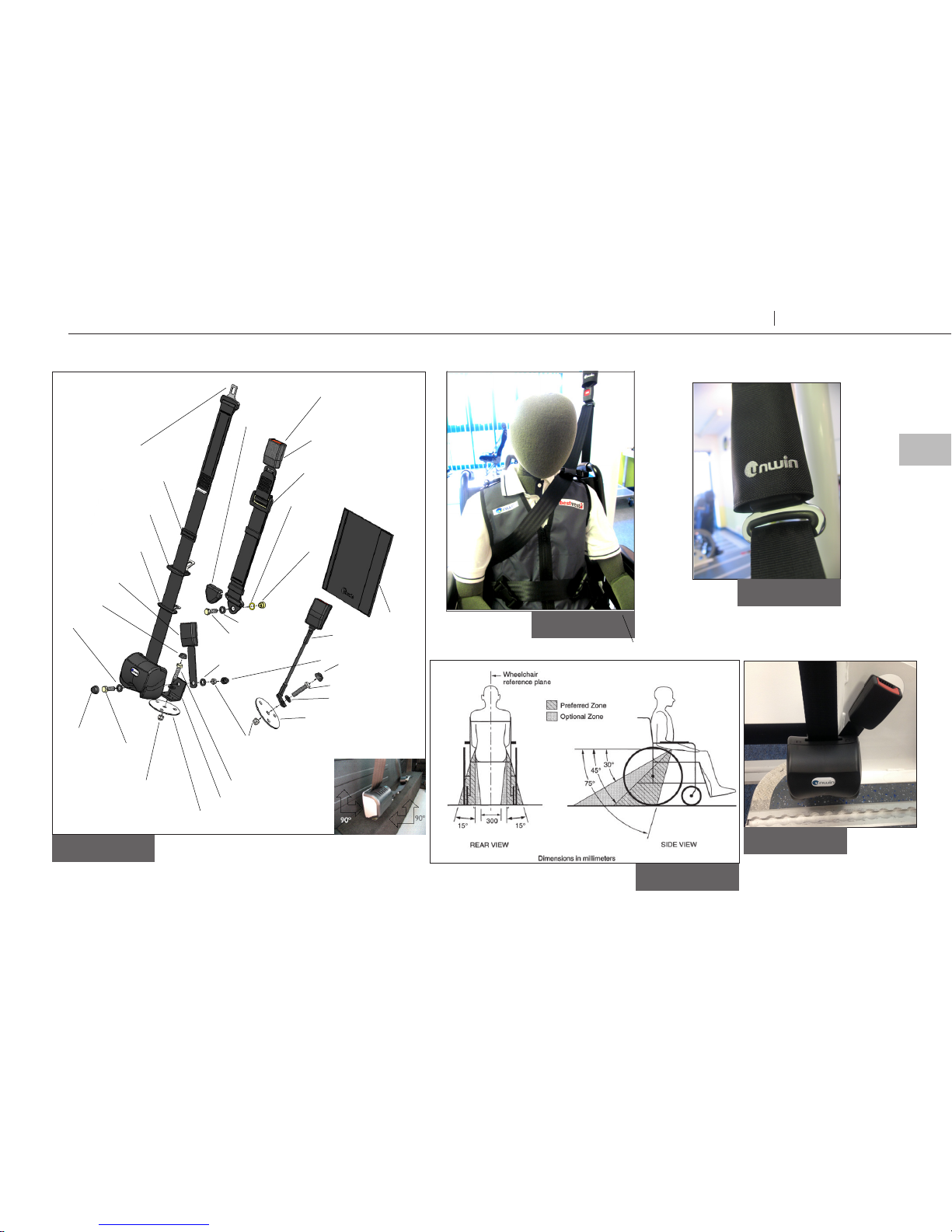
Fitting and using the 3 point WAV retractable occupant restraint
Fit and use
Bolted
1. The occupant restraint should be installed in accordance with previous safety information
section using the supplied hardware (Fig 12). Note: if fitting hardware, other than that provided
in this kit, is to be used then the fixing bolts should be of an equivalent cross section and an
equivalent grade namely B.S. Grade ’S’ (ISO 8.8)
2. The componentry is assembled (Fig 12) with the upper 3rd point and lower reel anchorage
points bolted to an approved anchorage position on the vehicle body.
Note: the upper 3rd point may be reversed as required, by unclipping the buckle from the
drop link tongue, reversing, and clipping back together. The inertia reel should be mounted at
an angle of 90/90° as viewed in 2 planes to the road level (see inset photo opposite). The reel
and its bracketry is bolted through the vehicle and reinforced on the underside, if required,
with the 100mm diameter load spreader plate and nyloc nut. All bolts should be tightened to a
torque of 40Nm. Note: All vehicle anchorage points may require reinforcement as necessary to
meet any required minimum strength recommendations for the vehicle.
3. Once installed check the free running of webbing into, and out of, the inertia reel and check the
‘lock up’ facility of the reel by engaging a short tug at various intervals along the extension and
retraction of the webbing in and out of the reel.
4. Adjust the drop link position at or above the shoulder height to comfortably suit the user, and
draw the running tongue across the occupant, through the fur thest arm of the wheelchair and
connect into the stalk to form a diagonal belt, Fig. 11.
5. Disconnect the fixed tongue from its buckle attached to the inertia reel, pass it through the
near arm of the wheelchair and connect back into the buckle forming the complete lap and
diagonal. (See Fig 11 & 13) The lap belt anchor points should be positioned to achieve belt angles
of 30° or more to the horizontal and preferably between 45° and 75° in order to fit low across
the pelvis reducing the possibility of the belt loading the abdomen, (Fig 5).
6. The pelvic restraint is designed to bear
upon the bony structure of the body and
should be worn low across the front of the
pelvis with any junctions between the pelvic
and shoulder restraints located near the
wearers hips.
7. Place the wrap around the drop link and
secure the Velcro to tidy the loose webbing
end. (Fig 14).
Removing occupant restraint
1. Unfasten the tongue from the stalks,
remove the occupant restraint and let the
webbing retract back into the housing.
2. The wheelchair tie-down should now be
removed as indicated on page 18 or 20.
Occupant restraints should not be held away
from the body by wheelchair components or
parts, such as armrests or wheels, and should
not be worn twisted in any way.
Occupant restraints should be adjusted as
firmly as possible and consistent with user
comfort. Upper torso restraints should fit
over the shoulder or shoulders.
18
Wheelchair & Occupant Restraints Occupant Restraints
Page 19
A
Figure 5
Fi g ur e 11
Figure 12
Figure 14
Fi gure 13
Figure 9
Plastic 3 bar slide
Running tongue
Drop link tongue
Flat washer
Bolt cap
7/16" unf x 1.5 bolt
7/16" unf nyloc nut
100 mm spreader plate
angle bracket
Flat washer
7/16" unf nyloc nut
Plastic nut cover
Bolt cap
Pillar loop
cover
Fixed tongue
7/16" unf x 1.5 bolt
Flat washer
Weavy washer
15m m
stepped
Drop link adjuster
Drop link buckle
3rd point anchorage
Drop link
Cover
Retractable occupant restraint
Flat washer
7/16" unf x 1.5 bolt
7/16" unf x 1.5 bolt
100 mm spreader plate
Buckle tang
Stalk
19
Wheelchair & Occupant Restraints Occupant Restraints
EN
Fit and use
Page 20

Equipment storage and maintenance
After care
• Store the restraints safely o the floor to avoid damage and ensure that it cannot
become a projectile in an accident. This can be achieved by using wall mounted
storage bag such as SLR111.
• Regularly inspect the Unwin restraints for damage, wear or malfunction. If any
problems are identified replace immediately.
• All webbings and components can be cleaned as necessary, but care should be
taken to prevent contamination of the webbings with polishes, oils and chemicals.
• To clean the straps use warm soapy water and a clean soft cloth. Rinse with clear
water and allow to air dry. To disinfect, use a mild spray disinfectant and do not
use products containing bleach. Important: when cleaning or disinfecting, do not
immerse buckles in the disinfectant or water.
• If the vehicle is involved in an accident when any restraints are deployed, remove
them from service and replace immediately. If in doubt please contact Unwin.
20
Wheelchair & Occupant Restraints Occupant Restraints
Page 21

Warranty
Unwin products are extensively tested using Unwin anchorage systems, and our full
warranty normally only applies to Unwin equipment when used with Unwin branded
anchorages or as instructed. Unwin have also participated in test programs with other
manufacturers anchorage products and will support warranty on the Unwin products
when used in conjunction with such jointly tested systems. For further details on
specific applications please contact the Sales Oce. In other situations, using Unwin
products, for which Unwin has not participated in a joint test program, a limited
Unwin warranty will apply.
21
Wheelchair & Occupant Restraints Occupant Restraints
EN
After care
Page 22

Declaration of conformity
Conforms to following directives
standards and regulations /
214/2014/EU Paragraphs 2.3.1 and 2.3.2
ISO 10542:2012
RESNA WC-4 2012 Section 18
R.107.06
2007/46/EC
Unwin, Martock August 2017
Chris Hellier
MD
Manufacturer /
Unwin
Unwin House
The Horseshoe Coat Road
Martock, Somerset, UK
Phone: +44 1935 827 740
E-mail: sales@unwinsafety.com
www.unwinsafety.com
Declares that the product /
Occupant Restraints:
DI, DK, STK, WK
Page 23

Accredited by URS as testing laboratory in accordance with ISO/IEC 17025:2005
Quality system certified in accordance with ISO 9001:2008
Illustrations, descriptions and specifications in the user manual are based on current product information.
Unwin reserves the right to make alterations without previous notice.
© 2017 Unwin
Page 24

UI2301A
facebook.com/UnwinSafety
twitter.com/UnwinSafety
linkedin.com/company/unwin
www.unwinsafety.com
UNWIN
Unwin House
The Horseshoe Coat Road
Martock, Somerset, UK
Phone: +44 1935 827740
E-mail: sales@unwinsafety.com
 Loading...