

Page 1

EN Instructions for fitting and use
Kit 5, Kit 8
Unwin User Manual
Page 2

2
Kit 5 and Kit 8 Wheelchair and occupant restraint kits
The following manual is an important part of the product, providing you with
information on how to achieve maximum performance and safe operation.
Keep the manual in a safe place so that you can refer to it when necessary.
If you have any questions about your equipment, please contact Unwin.
Once again, thank you for placing your confidence in our products!
Unwin
Thank you for choosing
Safe vehicle adaptation solutions
For your safety Unwin products are
designed and tested according to current
directives and standards.
S
A
F
E
V
E
H
I
C
L
E
A
D
A
P
T
A
T
I
O
N
Kit 5 or Kit 8
from Unwin!
Page 3

Safety information
4
6
8
Fit and use
10-21
10
16
After care
22
22
Limitations of use
General guidance
Before installing and using the kits
Fitting & using the wheelchair and occupant restraint kits
Floor rail - Kit 5
Floor anchor - Kit 8
Equipment storage and maintenance
Warranty
3
Wheelchair and occupant restraint kits Kit 5 and Kit 8
EN
Index
“Declaration of conformity” at the end of the manual.
Page 4

Limitation of use
Safety information
The development of Unwin kits is a continuous process. Applications are added on a
regular basis. For more detail contact Unwin or look on the Unwin website.
4
Kit 5 and Kit 8 Wheelchair and occupant restraint kits
Page 5

Kit 5
Kit 8
5
Wheelchair and occupant restraint kits Kit 5 and Kit 8
EN
Safety information
Page 6

General guidance
• Wheelchair Accessories that have not been approved by the Wheelchair Manufacturer must be
removed from the wheelchair and secured in the vehicle during transport to reduce the potential for
injury. Refer to ‘Instructions For Use in Transport’ provided with the wheelchair or contact wheelchair
manufacturer for further guidance.
• These wheelchair & occupant restraint kits comply with all applicable requirements of ISO 10542,
including a 48km/h, 20g frontal impact test using a forward facing 85kg surrogate wheelchair and an ATD
(test dummy) with a mass of 76.3kg. The test dummy was restrained by both a pelvic and upper-torso
restraint. Use of a pelvic only belt may compromise the performance of the WTORS system and should
be avoided.
• If the installation is to be used with an occupant head rest anchored to the vehicle, then a vehicleanchored back rest must be provided to minimise rearward deflection of the wheelchair seatback,
preventing neck injury.
• Regular inspection of all parts is recommended and the equipment should be used only if all
components are in good condition.
• Warning: protect webbing from contacting sharp edges and corners. Replace equipment if the
webbing does becomes cut, contaminated or frayed.
6
Kit 5 and Kit 8 Wheelchair and occupant restraint kits
Page 7

• Any restraints which have been subjected to a crash situation from which the vehicle must be towed
should, in the interest of safety, be replaced.
• Do not attempt to modify the equipment. For further advice on the installation and use of this tie-down,
please contact Unwin. Please read this manual fully before use.
• Avoid contact with corrosive liquids. Care should be taken to prevent contamination of the webbing
with polishes, oils and chemicals.
• The restraint kit anchorages should be installed by an experienced technician/vehicle converter.
Anchorages should not be installed into unsound materials such as corroded metal, wood, plastic and
fibre glass panels, without additional and suitable reinforcement.
• The equipment has been tested in a configuration similar to that recommended by Unwin, and any
deviation from the recommendations here is the responsibility of the installer/user. These instructions
refer use with both Unwin rails and Solo anchors, however the equipment may be used with any Unwin
proprietary rail product.
7
Wheelchair and occupant restraint kits Kit 5 and Kit 8
EN
Safety information
Page 8

Before installing and using the wheelchair & occupant restraint kits
• Ensure that the wheelchair is correctly maintained and that the settings of any adjustable parts are made
according to ‘Instructions for Use in Transport’.
• Whenever possible remove any items of luggage etc that may be attached to the wheelchair and secure
or store separately during transport in order to reduce the potential for injury to other passengers
travelling in the vehicle.
• Extra care must be exercised when using vehicle boarding aids such as passenger lifts or ramps during
the loading process. Refer to ‘Instructions For Use’ for information on safe slopes.
• Position the wheelchair facing forward - centrally in the designated region of the vehicle. Ensure the
wheelchair brakes are applied.
• To minimise the potential for head injuries in an impact, allow a clear space of at least 400 mm behind
and 650 mm, (FCZ, front clear zone), in front of the head of the wheelchair user, (Fig A). The shoulder
belt anchorage must be roof or side-wall anchored at a height level such that the belt webbing passes
over the midpoint of the occupant shoulder and at a height that is at or just above the level of the
occupants shoulders so as not to impose downward loads on the spine.
• A height provision (HHT) ranging from 1000mm to 1550mm should be made, depending on the size
of the passenger. There should also be 200 mm of clear space either side of the wheelchair centre line.
If these clear space dimensions cannot be provided then any should be adequately padded and comply
with impact performance requirements of ECE Regulation 21 ‘FMVSS 201’. All vehicle padding should
comply with the flammability requirements of ECE Regulation 118 ‘FMVSS 302’.
Note: seated head
height (HHT)
ranges from as low
as 1000mm for a
6-year-old child to
1550mm for a tall
adult.
8
Kit 5 and Kit 8 Wheelchair and occupant restraint kits
Page 9

• Wheelchair users, their carers and family are advised to check vehicle
specifications to ensure that sucient floor space is available to accommodate
the wheelchair and tie-down system. These distances are based upon the desire
to maintain clear zones for potential head excursions of occupants provided with
both upper and lower torso restraints.
• Users of heavy powered wheelchairs are also advised to check vehicle carrying
capacity. If in doubt consult the vehicle supplier for further details.
• Any airbag, as fitted to the vehicle, shall be used only as a supplementary
occupant restraint if designed to be used in combination with the Solar Quattro
and an appropriate occupant restraint.
• Installers of this tie-down should take note of any vehicle airbag position when
planning the installation. Airbags can cause serious injury if a wheelchair-seated
occupant is seated too close to an airbag position. If in doubt contact the vehicle
manufacturer or your National Automotive Regulatory Body for advice.
Figure A
9
Wheelchair and occupant restraint kits Kit 5 and Kit 8
EN
Safety information
Page 10

Fitting and using the wheelchair and occupant restraint Kit 5
Fit and use
Fitting front wheelchair tie-downs
1. The rail will have been installed in the vehicle in accordance with our own and
the vehicle converter’s instruction. Position the wheelchair within the vehicle as
required.
2. Install the front tie-down ATF (aluminium track fitting) into the front rail by aligning
the ATF feet with the cut-out sections of the rail, and locate into the rail, (Fig 1).
3. Press down on the ribbed part of the ATF, (Fig 1A), and push firmly towards the
wheelchair until the yellow plunger drops and locks into the rail.
4. Install the second front tie-down ATF in the same way, ensuring that each fitting is
opposite each other, if using rail lengths which have adjustability in ATF positioning.
5. Press the red buckle button(s) to release the webbed tongue, extend and pass
around each of the front wheelchair frame tie-down points, (Fig 2), (some
wheelchairs will indicate these tie-down positions, Fig 3). Reconnect the tongue
back into the buckle, creating an angle of around 40 to 60° within the front view
zone, (Fig 4).
6. Release the wheelchair brakes and pull back to tension the front tie-downs.
Re-apply the brakes.
10
Kit 5 and Kit 8 Wheelchair and occupant restraint kits
Page 11

Figure 1
A
Figure 2
Figure 4
Figure 3
11
Wheelchair and occupant restraint kits Kit 5 and Kit 8
EN
Fit and use
Page 12

Fitting and using the wheelchair and occupant restraint Kit 5
Fit and use
1. Place the combined rear webbing restraint into the rail
behind the wheelchair. It is acceptable to use the restraint
for either left-hand or right-hand use. The double inertia
reel should be fitted to the rail adjacent to the 3rd point
anchorage.
2. Select the combined wheelchair and occupant restraint so
that the karabiner gates face outboard from the wheelchair,
(Fig 5).
3. Attach each restraint into the floor rail by aligning the ATF
feet with the cut-out sections of the rail, (Fig 1). Note: the
yellow plungers must face toward the rear of the vehicle.
Press on the ribbed part of the ATF, (Fig 1A), and push
firmly down towards the wheelchair until the yellow plunger
drops and locks into the rail. If using rail lengths giving
adjustability on the positioning of the ATF, then ensure that
each ATF is sited opposite each other.
4. Remove the webbing from the Velcro patch and release
the over-centre buckle.
5. Attach the karabiner(s) to the wheechair main frame to
create an angle of about 30 to 45° within the rear view
zone, (Fig 6). (Some wheelchairs which indicate this tiedown position, Fig 7).
6. Pull the webbing through the over-centre buckle until it is
tight. With the free hand, begin to close the buckle. Once
the webbing is retained, fully close the buckle using both
hands, (Fig 8). Re-secure the Velcro to prevent the loose
end from becoming a trip hazard.
7. The occupant restraint must now be fitted.
Fitting rear combined webbing wheelchair tie-down and occupant restraint
12
Kit 5 and Kit 8 Wheelchair and occupant restraint kits
Page 13

Figure 1
A
Figure 5
Figure 6
Figure 7
Figure 8
13
Wheelchair and occupant restraint kits Kit 5 and Kit 8
EN
Fit and use
Page 14

Fitting and using the wheelchair and occupant restraint Kit 5 & Kit 8
Fit and use
3 point double inertia seatbelt
• Unwin recommends the use of a 3 point occupant
restraint system to provide greater protection in case
of an impact. However we also recognise that some
vehicle layout/designs or specific postural or medical
conditions do not allow that style of seatbelts to be
used easily.
• This system is not ISO 10542 compliant if used in 2
point configuration.
Fitting
1. Position the third point fixing into the cant rail, (Fig 9), so
that it is vertically above the inertia reel casing fixed onto
the floor fixing. Unfasten the tongue and buckle.
2. Pull the black webbing upwards and unfasten the tongue
from the grey webbing buckle.
3. Position the black webbing to form the lap belt and insert
the tongue into the buckle stalk, (Fig 10).
4. Ensure that the lap belt lays low on the pelvis of the
occupant, running as close as possible over the hips on
both sides.
5. Remove the black plastic cover on the grey shoulder belt
tongue and fit into the third point fixing.
• Before fitting the occupant restraint, ensure that the
reversible stalk orange button is facing outside in
relation to the wheelchair. If the reversible stalk orange
button faces inside, turn the stalk 180º to sit in the right
position.
• In accordance with International regulations, standard
Unwin occupant restraints are designed to be used for
passengers weighing 22kg or above. If the passenger
weighs less than 22kg, Unwin recommend that a suitable,
and appropriately tested child restraint seat is used.
This may involve a secondary seat belt restraint as
recommended by the original seat manufacturer.
6. Position the grey webbing to form the shoulder belt and
insert the buckle into the lap belt tongue.
7. Adjust the height of the shoulder belt to clear the occupant’s
shoulder by approximately 25mm - 1 inch, (Fig 11).
8. The lap belt anchor points should be positioned to achieve
belt angles of 30° or more to the horizontal and preferably
between 45° and 75° in order to fit low across the pelvis
reducing the possibility of the belt loading the abdomen,
(Fig 12). The pelvic restraint is designed to bear upon the
bony structure of the body and should be worn low across
the front of the pelvis with any junctions between the pelvic
and shoulder restraints located near the wearers hips.
14
Kit 5 and Kit 8 Wheelchair and occupant restraint kits
Page 15
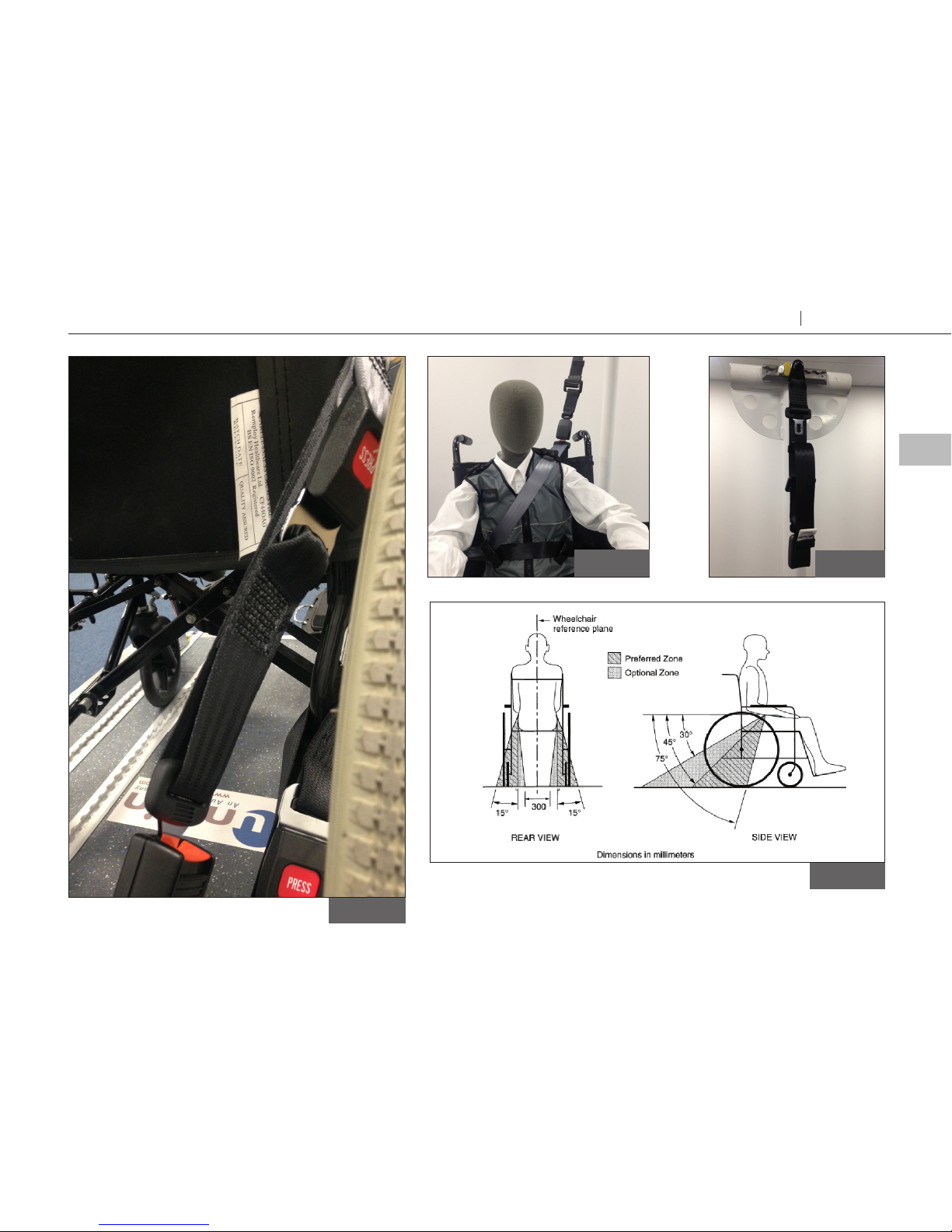
Figure 10
Fi g ur e 11
Figure 9
Figure 12
15
Wheelchair and occupant restraint kits Kit 5 and Kit 8
EN
Fit and use
Page 16

Fitting and using the wheelchair and occupant restraint Kit 8
Fit and use
Fitting front wheelchair tie-downs
1. The Solo floor anchors will have been installed in the vehicle in accordance with
their own and the vehicle converter's instruction. Position the wheelchair within
the vehicle as required.
2. Install each front tie-down cleat onto a front Solo floor anchor by aligning the
button within the cleat to the slot on the floor anchor. Slide the cleat fully home
(raising the anchor from its housing if using the retractable floor anchor, Fig 14), and
rotate the cleat through 90
° to align the tongue and buckle arrangement with the
wheelchair frame.
3. Press the red buckle button to release the webbed tongue, extend and pass
around each of the front wheelchair frame tie-down points, (Fig 2), (some
wheelchairs will indicate these tie-down positions, Fig 3). Reconnect the tongue
back into the buckle, creating an angle of around 40 to 60° within the rear view
zone, (Fig 4).
4. Release the wheelchair brakes and pull back to tension the front tie-downs.
Re-apply the brakes.
16
Kit 5 and Kit 8 Wheelchair and occupant restraint kits
Page 17

Figure 2
Fi gure 13
Protrusion
Indent
Figure 4
Figure 14
Figure 3
17
Wheelchair and occupant restraint kits Kit 5 and Kit 8
EN
Fit and use
Page 18

Fitting and using the wheelchair and occupant restraint Kit 8
Fit and use
Fitting combined rear Quattro wheelchair and occupant restraint
1. Place the combined rear Quattro restraint behind the wheelchair. It is acceptable
to use the restraint either for left-hand or right-hand use. The double inertia
reel should be fitted to the floor adjacent to the 3rd point anchorage. Ensure the
combined wheelchair and occupant restraints are fitted with the karabiner gates
facing outwards, (Fig 5).
2. Install the restraint(s) onto the floor anchor(s) by aligning the button within the
cleat, to the slot on the floor anchor(s).
3. Slide the cleat fully home (raising the anchor from its housing if using the
retractable floor anchor, Fig 14), rotate the assemblies through 90
° to allow the
karabiners to be attached to the wheelchair frame.
4. Press the yellow Quattro release button(s), (Fig 15A), to extend the webbing and
attach the karabiner(s) around the wheelchair main frame. Some wheelchairs will
indicate this rear frame tie-down position, (Fig 7).
5. Press each Quattro release button once again to take up the slack in the webbing
and create an angle of around 30 to 45° and within the rear view zone, (Fig 12).
6. Final tensioning is achieved by turning each tensioning handle, (Fig 15B), until the
webbing is equally taut on each side.
7. The occupant restraint must now be fitted. See page 14.
18
Kit 5 and Kit 8 Wheelchair and occupant restraint kits
Page 19

Figure 15
Figure 12
Figure 5
Fi gure 13
Protrusion
Indent
Figure 14
Figure 7
A
B
19
Wheelchair and occupant restraint kits Kit 5 and Kit 8
EN
Fit and use
Page 20

Removing the wheelchair and occupant restraint Kit 5
Fit and use
1. Release the grey shoulder belt from the lap belt section, from the third point fixing
and carefully allow the shoulder belt to return to the retractor.
2. Disconnect the black lap belt from the buckle stalk on the aise side and carefully
allow the lap belt webbing to return to the retractor.
3. Connect the shoulder belt buckle to the lap belt tongue above the opening of the
retractor box.
4. Before releasing the restraint, ensure the wheelchair brakes are applied.
5. Release the over-centre buckle on the rear strap, loosen the webbing and remove
the karabiner from the wheelchair frame. Close the over-centre buckle and replace
the webbing to the Velcro.
6. To remove the ATF from the floor rail,
lift the yellow plunger fully and slide back
away from the wheelchair to align the ATF feet with the rail cut outs, lift away
from the rail and store securely.
7. Push the wheelchair forward to loosen the front straps.
8. Release the front strap buckle by pressing the red button and remove it from
the wheelchair frame. Reconnect the tongue and buckle.
9. Remove the ATF from the floor rail and store kit securely.
20
Kit 5 and Kit 8 Wheelchair and occupant restraint kits
Page 21

Removing the wheelchair and occupant restraint Kit 8
Fit and use
1. Release the grey shoulder belt from the lap belt section,
from the third point fixing and carefully allow the shoulder
belt to return to the retractor.
2. Disconnect the black lap belt from the buckle stalk on the
ailse side and carefully allow the lap belt webbing to return
to the retractor.
3. Connect the shoulder belt buckle to the lap belt tongue
above the opening of the retractor box.
4. Before releasing the restraint, ensure the wheelchair brakes
are applied.
5. Release the tension in the rear tie-downs by pressing the
yellow button and extending the webbing to allow the
karabiner to be removed from the wheelchair frame. If
the webbing is particularly tight, it may be necessary to
slightly ’tension’ the webbing with the hand wheel, whilst
pressing the yellow button, to remove the webbing lock
on the Quattro.
6. To remove the cleat from the floor anchor, turn the cleat to
align the raised protrusion on the cleat with the indent on
the floor anchor and slide o (Fig 13). Note: protrusion and
indent features are only applicable to retractable anchors
and not static anchor S10. In such case, turn the cleat back
through the 90
° of instalment and slide o).
7. Push the wheelchair forward to loosen the front straps.
8. Release the front strap buckle by pressing the red button
and remove it from the wheelchair frame. Reconnect the
tongue and buckle.
9. Turn the cleat to align the raised protrusion on the cleat
with the indent on the floor anchor and slide o. Store kit
safely.
21
Wheelchair and occupant restraint kits Kit 5 and Kit 8
EN
Fit and use
Page 22

Equipment storage and maintenance
After care
• Store the restraint safely o the floor to avoid damage and ensure that it cannot become
a projectile in an accident. This can be achieved by using wall mounted storage bag such
a s SL R111.
• Regularly inspect the wheelchair and occupant restraint systems for damage, wear or
malfunction. If any problems are identified replace it immediately.
• When not in use, keep loose occupant webbing ends connected to their corresponding
buckle sleeves, etc, to prevent them from becoming tripping hazards and from flailing
around when the vehicle is in motion.
• All webbing and components can be cleaned as necessary, but care should be taken to
prevent contamination of the webbings with polishes, oils and chemicals, particularly
battery acide.
• To clean the straps use warm soapy water and a clean soft cloth. Rinse with clear water
and allow to air dry. To disinfect, use a mild spray disinfectant and do not use products
containing bleach. Important: when cleaning or disinfecting, do not immerse
or flood buckles, karabiners or Solo fittings in the disinfectant or water.
• If the vehicle is involved in an accident when any restraints are deployed, remove them
from service and replace immediately. If in doubt please contact Unwin.
Warranty
Unwin products are ex tensively tested using Unwin anchorage systems, and our full warranty
normally only applies to Unwin equipment when used with Unwin branded anchorages or as
instructed. Unwin have also participated in test programs with other manufacturers anchorage
products and will support warranty on the Unwin products when used in conjunction with
such jointly tested systems. For further details on specific applications please contact the Sales
Oce. In other situations, using Unwin products, for which Unwin has not participated in a
joint test program, a limited Unwin warranty will apply.
22
Kit 5 and Kit 8 Wheelchair and occupant restraint kits
Page 23

Declaration of conformity
Conforms to following directives
standards and regulations /
214/2014/EU Paragraphs 2.3.1 and 2.3.2
ISO 10542:2012
RESNA WC-4 2012 Section 18
R.107.06
2007/46/EC
Unwin, Martock, 9 November 2017
Chris Hellier
MD
Manufacturer /
Unwin
Unwin House
The Horseshoe Coat Road
Martock, Somerset, UK
Phone: +44 1935 827 740
E-mail: sales@unwinsafety.com
www.unwinsafety.com
Declares that the products /
KIT5 & KIT8
Accredited by URS as testing laboratory in accordance with ISO/IEC 17025:2005
Quality system certified in accordance with ISO 9001:2008
Illustrations, descriptions and specifications in the user manual are based on current product information.
Unwin reserves the right to make alterations without previous notice.
© 2017 Unwin
Page 24

UI2302A
facebook.com/UnwinSafety
twitter.com/UnwinSafety
linkedin.com/company/unwin
www.unwinsafety.com
UNWIN
Unwin House
The Horseshoe Coat Road
Martock, Somerset, UK
Phone: +44 1935 827740
E-mail: sales@unwinsafety.com
 Loading...