

USER
MANUAL
APPLICABLE TO
SLASH OL/SLASH PLUS/SLASH PLUS UDP
SLASH PRO OL/SLASH PRO/SLASH PRO UDP
SLASH J UDP/SLASH DJ2
UNIZ DESKTOP 3D PRINTER

DISCLAIMER
lease read and understand the contents of this user manual carefully. Failure to read
P
in order to operate the device smoothly, efficiently and safely.
The conditions or methods used for assembling, handling, storage, use or disposal of the
device are beyond the control of UNIZ Technology LLC. For this and other reasons, UNIZ does
not assume responsibility and expressly disclaim liability for loss, injuries, damage, or expense
arising out of or in any way connected with the assembly, handling, storage, use or disposal of
the product.
The information in this document was obtained from sources which we believe are reliable.
However, the information is provided without any warranty, express or implied, regarding its
correctness.
the manual may lead to personal injury, inferior results or damage to the SLASH. All
users who operate the Slash are expected to understand the contents of the manual

CONTENTS
A
B
C
WELCOME
DESIGN RULES
D
SLASH SERIES 3D PRINTER DESIGN RULE
SETTING UP YOUR PRINTER
UNBOXING
PRODUCT DESCRIPTION
SLASH PRINTER TYPES
ACTION BUTTON COLOR GUIDE
PRINTER ACTIVATE AND UPGRADE
UNIZ SOFTWARE USER
MANUAL
···········································02
·····················01
························04
····························06
·············07
·········18
TROUBLE SHOOTING
E
TROUBLE SHOOTING
ROHS AUTHENTICATION
F
ROHS AUTHENTICATION
APPENDIX
G
SOFTWARE INTERFACE
START YOUR FIRST PRINTING JOB
ADDITIONAL TOOLS
··························17
··········19
·······························32
TECHNICAL SPECIFICATIONS
·······································33
·····························34
························42
··················43

WELCOME
A
SLASH SERIES 3D PRINTER
his user manual is designed to help you start your SLASH series 3D printer
T
great quality prints.
You might be familiar with other types of 3D printers. Regardless, it is still essential
that you read this manual carefully in order to make the most out of your SLASH
printer.
experience. Learn everything about using your SLASH 3D printer by following
the instructions in this user manual and experience how easy it is to produce
01
Federal
Communications
Commission
Conformite
Europeenne

SETTING UP YOUR
B
UNBOXING
The SLASH comes in reusable, durable packaging that has been specially designed to protect your
SLASH in transport. To properly unpack your SLASH, please follow the steps described below.
START UNBOXING
Start unpacking by correctly orienting the cardboard box, then slide the foam packaging out of the
box by pulling the cardboard handle beneath the printer while holding the box.
PRINTER
UNBOXING
OPEN IT UP
On the foam packaging, you will find the Quick Start Guide and accessories.
REMOVE THE FOAM PACKAGING
In the foam part on top of your SLASH, you will find all accessories of your SLASH. Take these out
and put them aside. Open up the package by removing the foam wrap at the middle. Now you can
take out the SLASH and place it on your desk. Make sure you hold the SLASH by the aluminium
casing while carrying it.
REMOVING PROTECTION
There is some packaging material around the machine. You may remove it.Then, your SLASH is
ready for use!
02
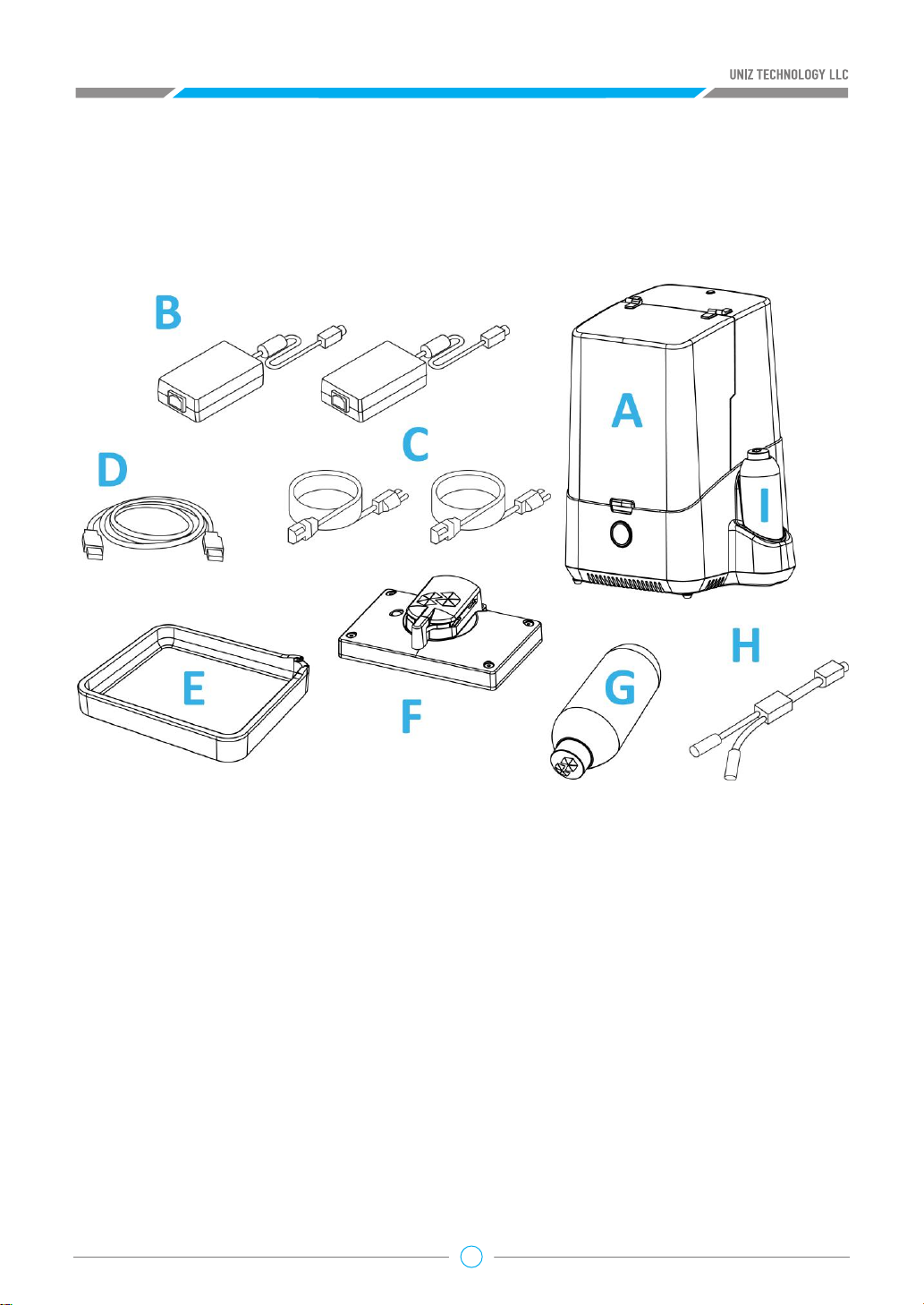
PACKING LIST
Supplied with your package is the UNIZ desktop 3D printer and several other accessories. This is
everything you need to start printing. Check if all accessories are included before continuing.
UNIZ Desktop 3D Printer
A .
Power Adapter x 2
B .
Power Cable x 2
C .
USB Cable
D .
Resin Tank
E .
Building Platform
F .
Resin Bottle
G .
Power Combiner
H .
Cleaning Bottle
I .
03
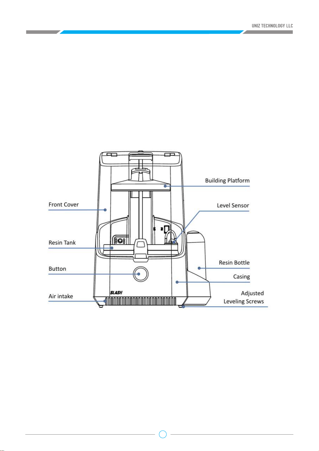
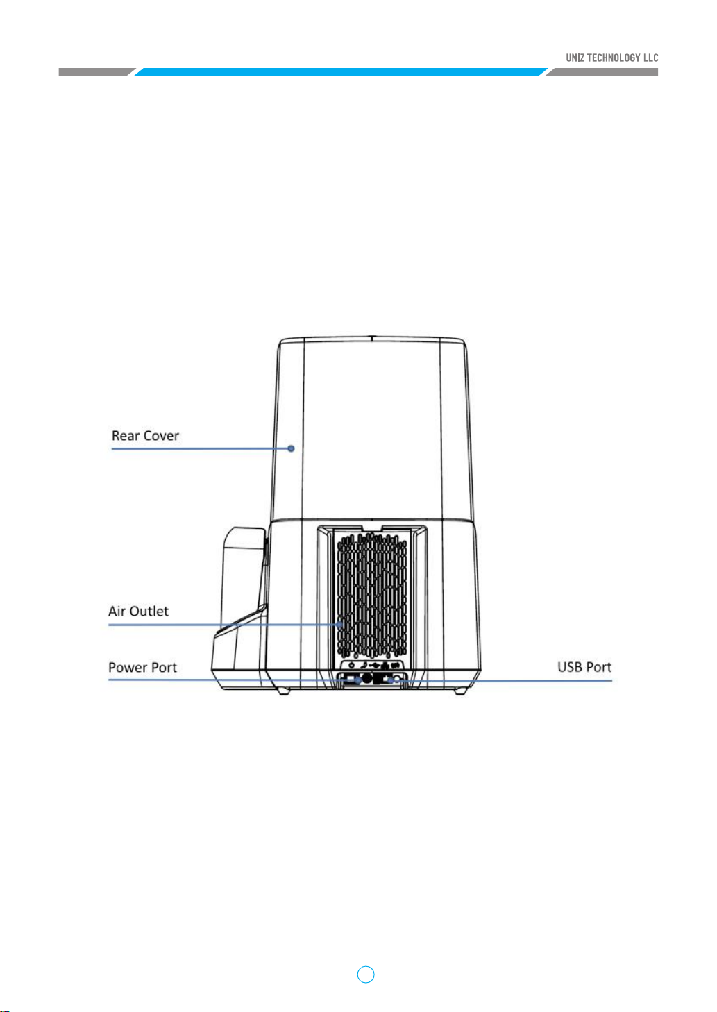
PRODUCT DESCRIPTION
04
05
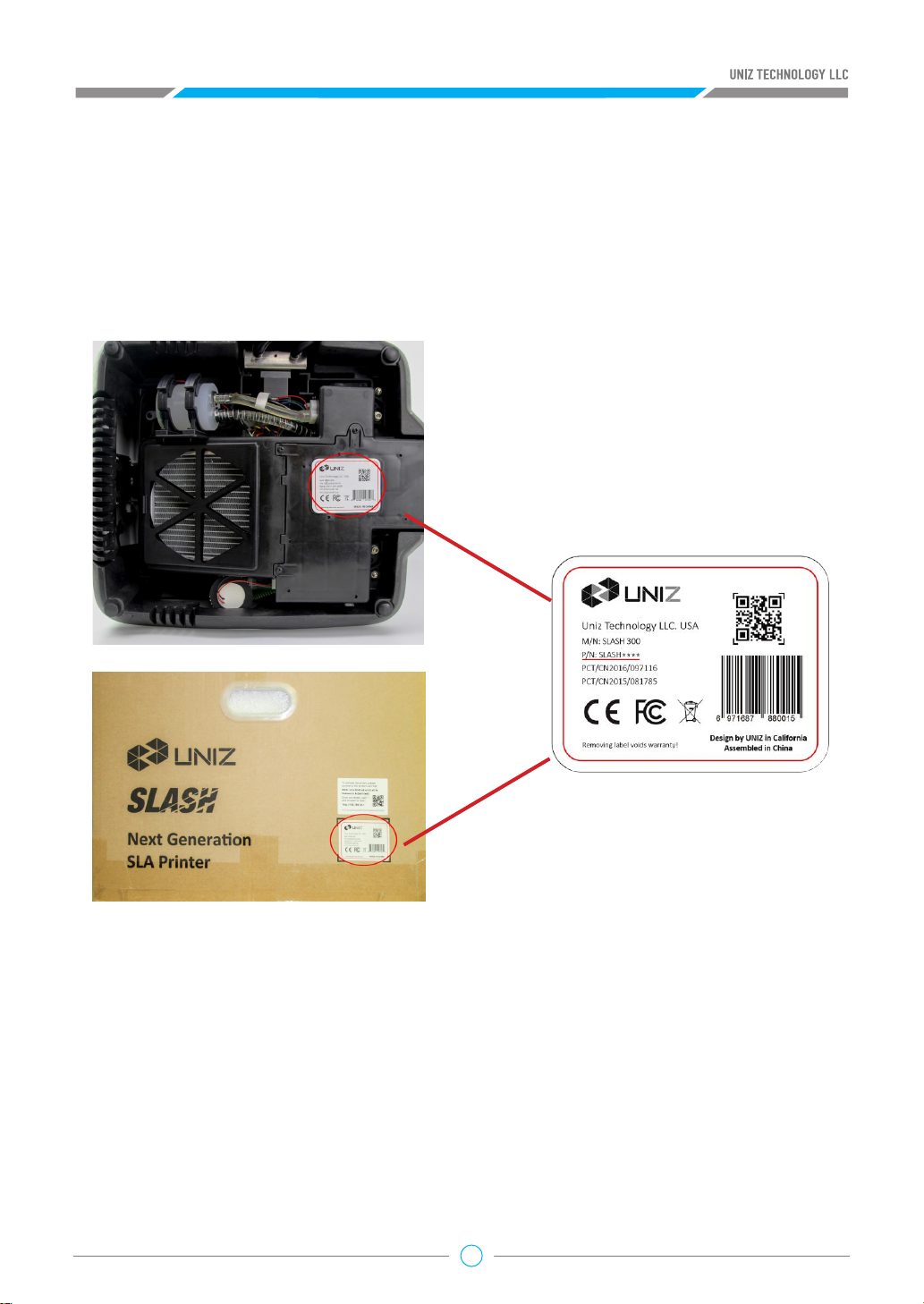
SLASH PRINTER TYPES
You can identify the printer’s type by checking the label
underneath the printer and on the box.
06
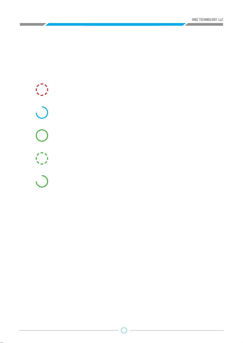
ACTION BUTTON COLOR GUIDE
Breathing red
Printer busy (starting up/paused/z axis moving)
Progressing blue
Data transfer in progress
Green
STANDBY-The printer is connected and waits for a command.
Breathing green
Data transferred, waiting for touch confirmation.
Progressing green
Printing in progress-The lights indicate completed progress.
07
PRINTER ACTIVATE AND UPGRADE
1. Printer Network
Check if the printer is connected to the Internet and set up for the printer connection.
Note:
The Printer's Wi-Fi feature supports 2.4GHz band only, it does not support 5 GHz connections.
Method 1: UNIZ Desktop
1. Plug into a power supply and switch on the printer.
2. Connect the printer and PC via USB and start the software.
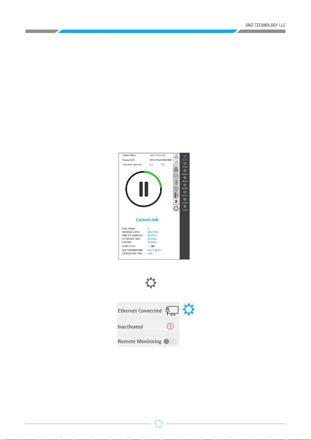
3. Select the printer in the list to open the printer control interface.
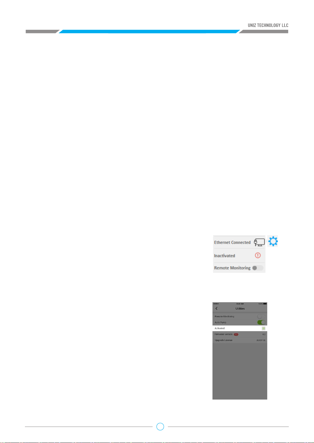
4. View network status
Press the “Printer Settings” button open the submenu. The first item is
the Network which shows the connection status.
configued.
configured
●
Wi-Fi Disconnected means the current Wi-Fi is not connected and needs to be
●
Wi-Fi Name means the current Wi-Fi is connected.
●
Ethernet Disconnected means the current Ethernet is not connected and needs to be
●
Ethernet Connected means the current Ethernet is connected.
08
5. Set up the network
This function only supports setting via USB connection.
●
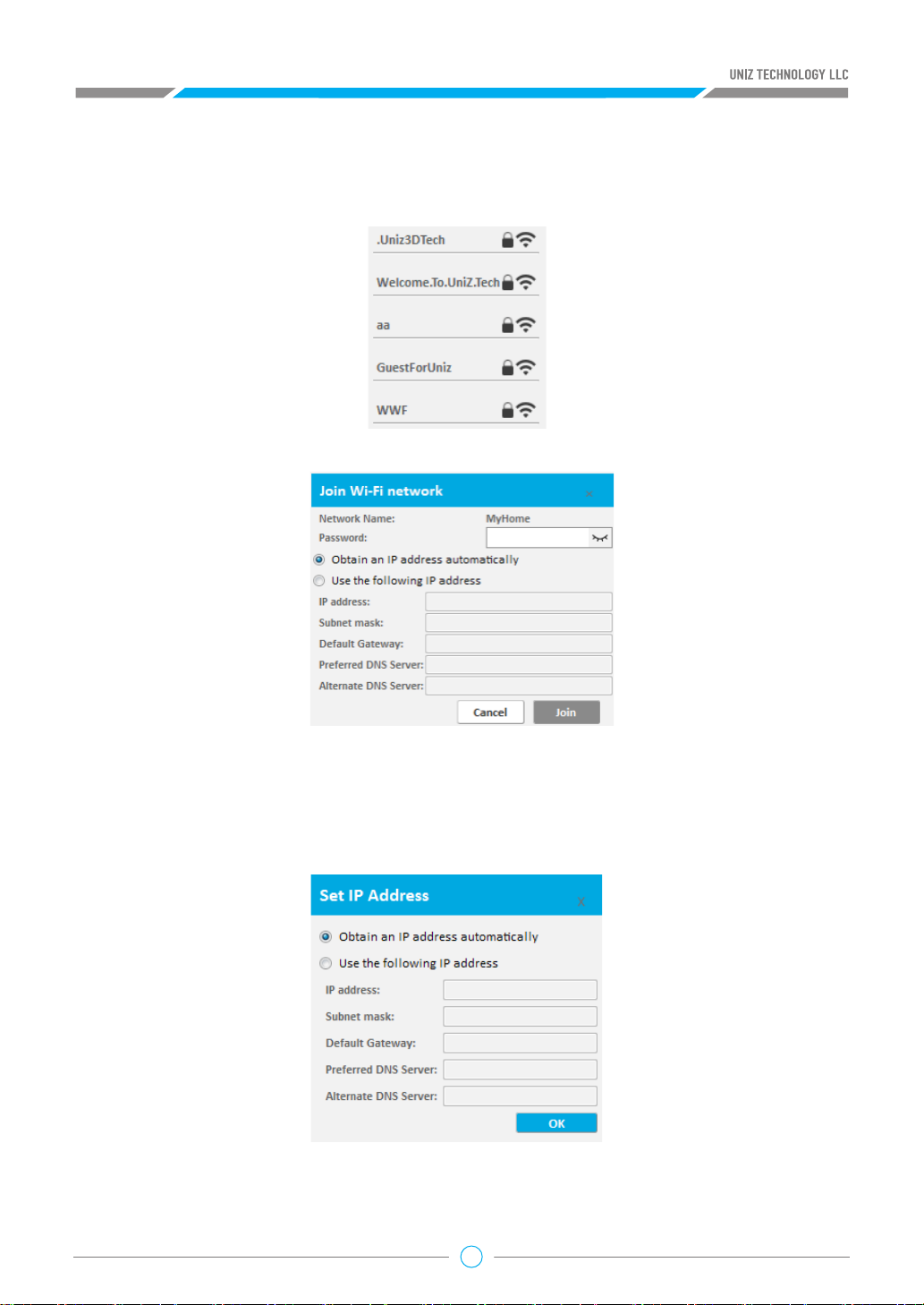
Click the first item. The Wi-Fi list will pop up in the left if it is Wi-Fi connection;
Click the Wi-Fi name on Wi-Fi list configure the IP address settings.
In the box you can enter password and obtain IP address automatically or set fixed IP
address manually.
●
Click the first item. The IP address settings should pop up if you are connected via Ethernet.
(software should be 1.2.0 or higher version and firmware should be 4.1 or higher version).
In the box you can obtain IP address automatically or set fixed IP address manually.
09

Method webpage·
1. Plug into a power supply and switch on the printer.
2. Connect to the printer's Wi-Fi hotspot.
a. Find the SSID and Password on the side label.
b. Access the Wi-Fi Setting of your mobile device, and connect to
UNIZ3D##:##:##:##:##:## as shown in the SSID.
3. Check and Set Network.
a. Find IP address on the side label.
b. Open the browser on PC or mobile device and enter the IP address; open the printer page
and select the "Network" option.
10
c. Click Check Network to check if the printer is connected to your network.
d. If the printer is not connected to the Internet, please choose your home Wi-Fi hotspot, type in
the password and click the Connect button.
e. After the printer is connected to your home Wi-Fi hotspot and Internet, disconnect your PC or
mobile device from the printer Wi-Fi and reconnect to home or office network.
Tips:
After setting up the connection, please make sure that PC or mobile device and printer are
connected to the same LAN to ensure that PC or mobile phone can control the printer through
the network.
2. Activate the printer
Before activation, make sure that the printer is powered on and connected to the network. Slash OL
or SLASH PRO OL models must be activated before printing. After successful activation, the printer
will automatically launch a seven-day trial period in which the SLASH OL/PRO OL will become and
function as a SLASH PLUS UDP/SLASH PRO UDP.
Method 1: UNIZ Desktop
a. Start the UNIZ Desktop and select the printer in the list to open the printer control interface
b. Click the “Printer Settings” button to open the submenu. The second option shows the activation
status
c. Click the item to execute the activation function.
If the printer is inactivated, clicking this item will activate the
printer and the system will bind the printer to the currently
logged-in user.
Method 2: UNIZ App
Printer activation is supported by UNIZ App of 1.2.0 or higher.
a. Click the "Printer" button in the main menu of App, find the
printer that needs to be activated in the list of printers, and
open the printer control panel.
b. Click the "Utilities" button on the control interface to enter
the setting interface. The third item is the activation function,
showing the activation status ("Inactivated "or" Activated ").
c. Click “Inactivated”/ “Activated” to activate/reactivate the
printer with the current login account.
11
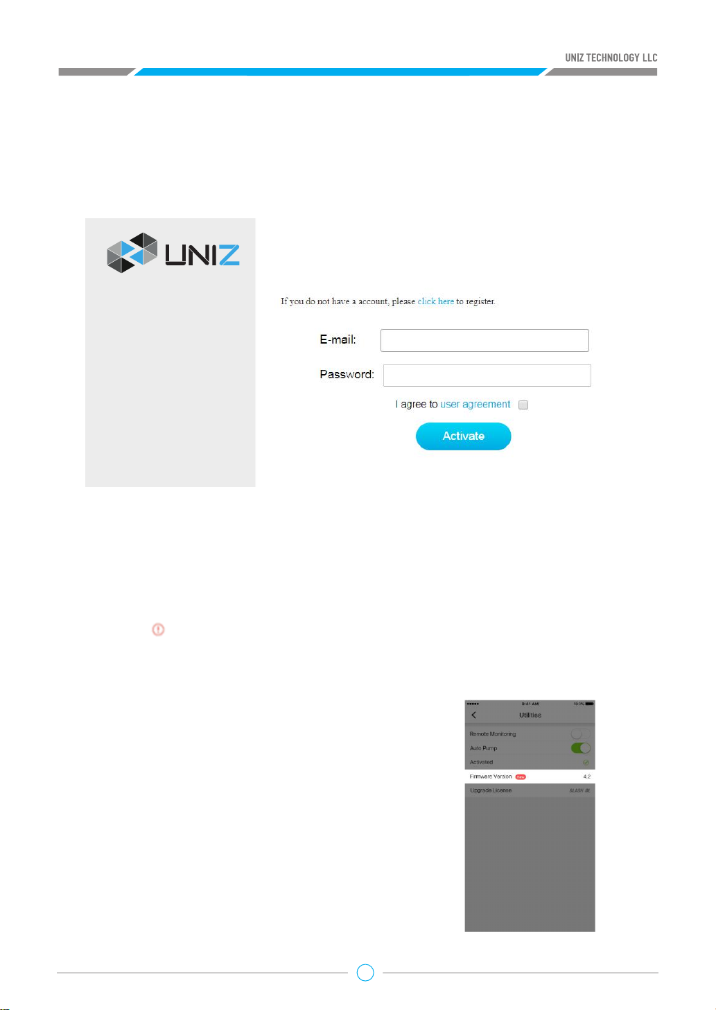
Method 3: Activate from the webpage
a. Connect the PC or mobile device to the printer’s Wi-Fi and open the printer page in the
browser.
b. Select the Activation tab in the printer page and input UNIZ account and password, then click
the Activate to complete the activation.
Network
Activation
Upgrade
3. Updating the Firmwaret
Before upgrading the firmware, make sure that the printer is powered on and is connected to the
internet.
Method 1: Upgrade from the UNIZ Desktop
a. Launch the software and select the printer to open the printer control interfacet.
b. An icon will show next to the firmware version when there is a new version available.
available. Click the icon to start upgrading. Restart the printer when the upgrade is finished.
Method 2: Upgrade from the UNIZ App
(1) Check the firmware version of the current printer
Click "Printer" in the main menu of App, find the printer
that needs to be updated in the list of printers, open
the printer control panel, click the "Utilities" button,
and you can see the current firmware version in the
window.
(2) Updating the firmware
An icon “New” will show next to the firmware version
when there is new version firmware available. Click the
icon to start upgrading. Restart the printer when the
upgrade is finished.
12
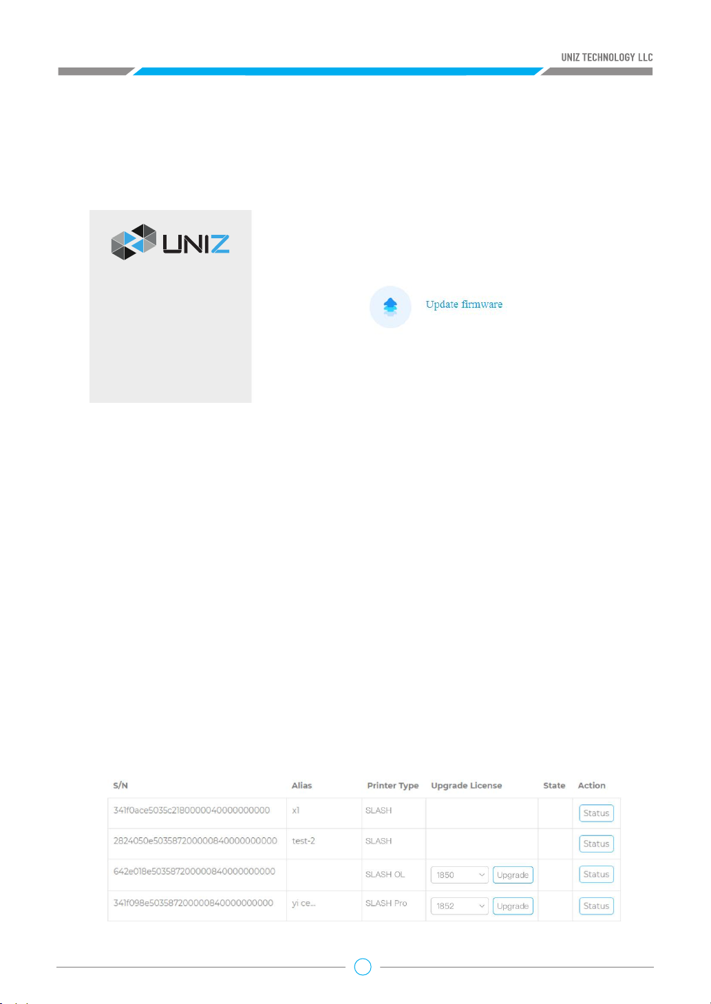
Method 4: Upgrade from the webpage
a. Connect the PC or mobile device to the printer Wi-Fi and open the printer page in the browser.
b. Select the Upgrade tab in the printer page and click Upgrade firmware to start the printer
firmware updated. Restart the printer after the upgrade is complete.
Network
Activation
Upgrade
4. Upgrading the Printer License
Before Upgrading the license, make sure that the printer is powered on and is connected to the
network.t
Software Requirements:
UNIZ APP 1.2 or higher
UNIZ Desktop 1.2 or higher
Printer Firmware 4.0 or higher
SLASH OL and SLASH PRO OL support license upgrades. The printer type will change as follows:
SLASH OL -> SLASH PLUS UDP
SLASH PRO -> SLASH PRO UDP
(1) You can purchase license upgrades from the online store by visiting official website https://
www.uniz.com.
(2) Click My Printer in the left menu of the Dashboard from the website to show the activated
printers under the current username and choose the one that needs to be upgraded. Select the
purchased license in the Upgrade License list and click Upgrade to complete the process.
13
Tips:
The printer will be shown only when activated with the current account.
(3)License upgrades can be executed in the UNIZ App or
the UNIZ Desktop printer control interface.
●UNIZ Desktop
a. From the ‘connected printers menu’ in the top right,
select the printer in the list of printers, and open the
printer control interface.
b. Click the "Upgrade License" button below
If the user has not purchased the license or if the printer
and the license have not been bound, the system will
display a notification that directs to the purchasing
webpage.
If the printer and the license have been bound, the system
will start the upgrading process.
Please restart the printer manually after the upgrade is
complete. The printer model should change upon the next
power up.
●UNIZ App
a. Click the "Printer" button in the main menu the app,
select the corresponding printer in the list of printers, open
the printer details control panel, click the "Utilities" button,
and the “Upgrade License” option can be seen in the
window.
b. Click the “Upgrade License” option
If the user has not purchased the license or if the printer
and the license have not been bound, the system will link to
the corresponding license purchasing webpage or remind
the user to go Dashboard for binding;
If the printer and the license have been bound, the system
will start the upgrading.
Please restart the printer manually after upgrade is
complete and the printer model will shift into the
upgraded model.
14
5. Trial and Trial Expiration
SLASH OL and SLASH PRO OL models automatically get a seven-day free trial with SLASH PLUS UDP
or SLASH PRO UDP models after successful activation.
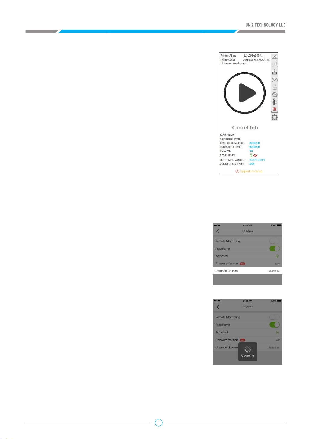
In trial
During the trial period, check whether the printer is connected to the Internet and whether the
resin bottle information is normal before printing.
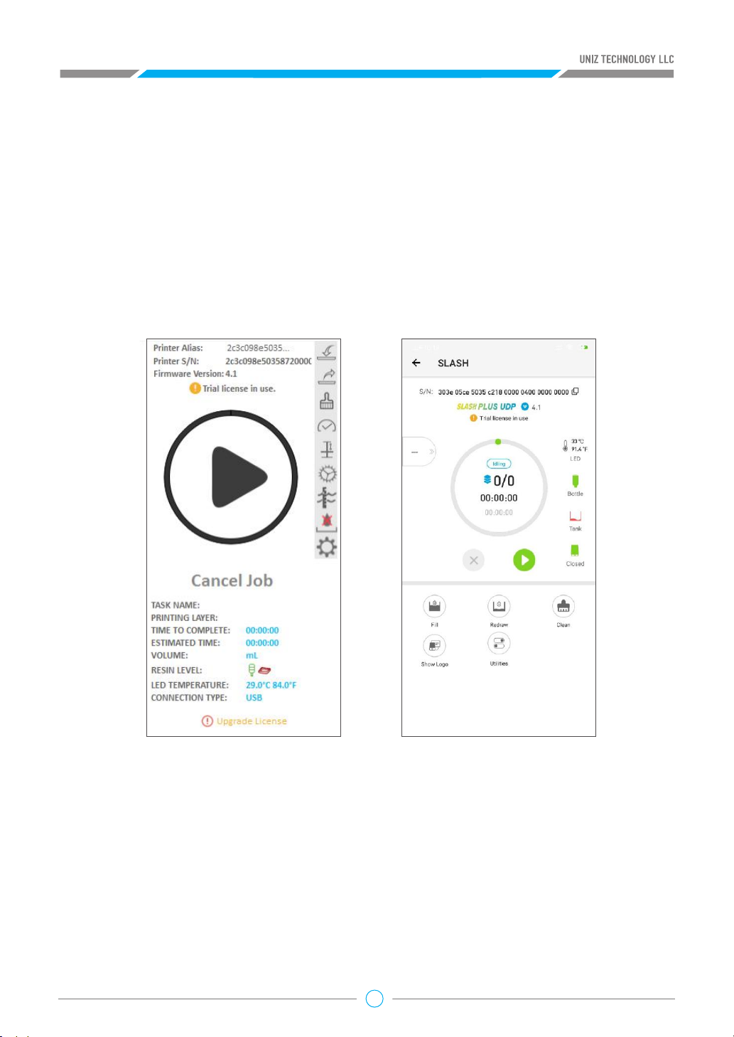
During the trial period, the trial status will be shown under the firmware version in the printer
control panel (ln use/Expired).
On the left is the Desktop printer control interface, and on the right is the App printer control
interface.
15

Trial Expiration
(1) If the trial period has expired, the system will pop up the dialog box as shown below after
opening software control panel or clicking “Starting Print”.
(2) Click “OK” and the printer will perform the printer reset operation. After the reset operation is
completed, the system will prompt as below
.
(3) After the next restart, the printer will be restored to its original model.
16

UNIZ SOFTWARE USER
C
1. Software Interface
Open UNIZ Desktop and click Control button to show the 3D model viewer.
MANUAL
1.1 Viewer
17
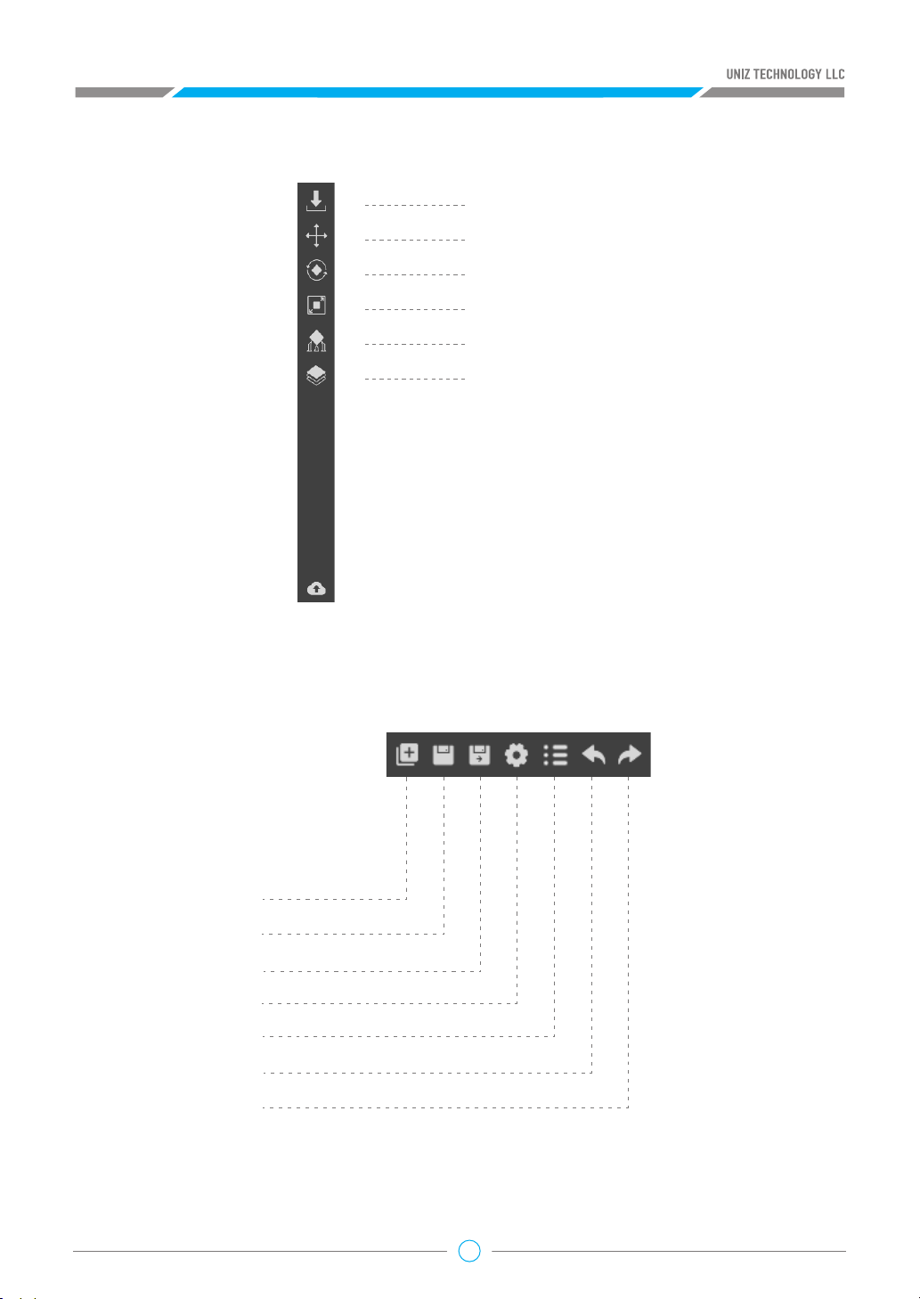
1.2 Main Tools
Load 3D Models
Move Selected Model
Rotate Selected Model
Scale Selected Model
Generate Supports
Slice
1.3 Additional Tools
New Scence
Save Scence
Save Scence as
Advanced Setting
Model List
Undo Operation
Redo Operation
18

1.4 Printer Control
Uniz provides printer control function based on USB and network connection. This function also
supports multiple printers’ control. Printer connected via USB will be marked with the icon in
the right printing tool bar.
Click the Search button in the tool bar to search all the printers (only selected printer type) in
the same network of the computer which will be marked with the icon.
Printer connected via both USB and network will be marked with the icon and USB
communication will be prior.
1.5 Status Bar
The status bar appears along the lower edge of the window and shows software progress, such as
loading, generating supports, and slicing
Loading: 58%
2. Start Your First Printing Job
2.1 Load 3D Models
To load one or more 3D models, you may either drag-and-drop onto the 3D viewer, click Load File
Button from the Main Tools, or double click on the file directly (if UNIZ Desktop+ is set as default
software to open such file format). Supported file formats: STL, OBJ, AMF, 3MF and UNIZ.
Tips: UNIZ file does not support multiple loads in parallel.
2.2 Select Object(s)
Click the left mouse button on an object to activate it for further operations. Click and drag the
pointer across objects to select multiple objects. The activated objects will turn blue once selected.
19

2.3 Change View
Viewing your model from preferred angle will benefit model positioning. To rotate the view, right
click and drag around the activated object. To pan, hold the shift key and click-drag with right
mouse or hold down the scroll wheel and move mouse around. To zoom in or out, use the scroll
wheel.
2.4 Change Position
Pressing the “Position” Button will open following sub menu.
• Once the Position tab is open, hold the left mouse
button on the object and move the mouse to move
the object freely in the X-Y plane. If the “Shift” key is
held down, the object will be moved up and down
along the Z-axis instead.
• The activated object can also be moved by inputting X/
Y/Z values in the field, press “Enter “to apply changes.
• Bring the active part in contact with platform.
• Use the “Centered” button to center active part on
platform.
• Use the “Duplicate” button to duplicate the active
part.
Tips:
Make sure the models are distributed evenly on build platform. Un-balanced forces on the
build platform may result in inferior precision or cracking of the printed parts. Once supports
are attached to a model, its Z-position cannot be modified.
2.5 Change Orientation
Press the “Rotation” Button on the main tools will open following sub menu.
• Once the Rotation tab is open, hold the left mouse
button on the object and move the mouse to freely
rotate the object.
• Rotate any model more precisely in one of the three
main axes by dragging one of the circular rings on the
manipulator.
• The activated object can also be rotated by inputting X/
Y/Z values in the field. Press “Enter” to apply changes.
UNIZ's orientation tools are relative not absolute, so
the X, Y, and Z rotation angles reset to 0 degrees after
applying a rotation.
• Press “To Align Bottom Plane” button to align the
selected plane to the bottom of build platform.
• Click the “Reset” Button to restore the activated object to the original status.
20

Tips:
Large Flat surfaces or Long Straight lines with supports may be printed at an oblique angle
of at least 10° to the build platform to increase the success rate. The forces during peeling
may distort thin layers of a flat surface or a line mounted on the support structures if printed
horizontally. If a planar surface or thin line is oriented at an oblique angle, there is only little
overhang for each new layer. Furthermore, thin-walled parts occupy significant less area in a
slice when printed at an oblique angle.
2.6 Change Size
Press the “Size” Button on the main tools will open following sub menu.
• Once the Size tab is open, the activated object can be
scaled freely by holding the left mouse button on the
object and moving the mouse.
• The activated object can also be scaled by inputting X/
Y/Z values in the field. Press ‘Enter’ to apply changes.
The object will scale uniformly in Uniform Scaling
mode. In Non-uniform Scaling mode the object will
scale independently for each axis without affecting the
other axes.
• If you prefer to scale to a fixed ratio put a value into the
scale box.
• Click the ‘Reset’ Button to restore the activated object
to the original size.
• Units: toggle between millimeters and inches.
Tips:
Changing an object’s size will break previously generated supports and you will need to redo
these.
21

2.7 Generate Supports
Some models need additional support structures to print successfully, especially those with
overhangs. Press the “Supports” Button on the main tools to open the Supports sub menu.
Once the Supports tab is open, supports can be added to the active object by pressing the
“Generate” button. Support parameters can be adjusted using spacing, Support Diameter, Head
Length, and Point Size sliders.
• Spacing defines the closest distance between two
adjacent supports.
• Support Diameter defines the diameter of the support
pillar.
• Head Length defines the length between the straight
support pillar and angled pillar to the object (point).
• Point Size defines the diameter of the support where it
touches the object.
• Internal Supports, checking this box will generate
supports inside the model to shore up overhangs.
Without internal supports, the overhangs may fail
during print.
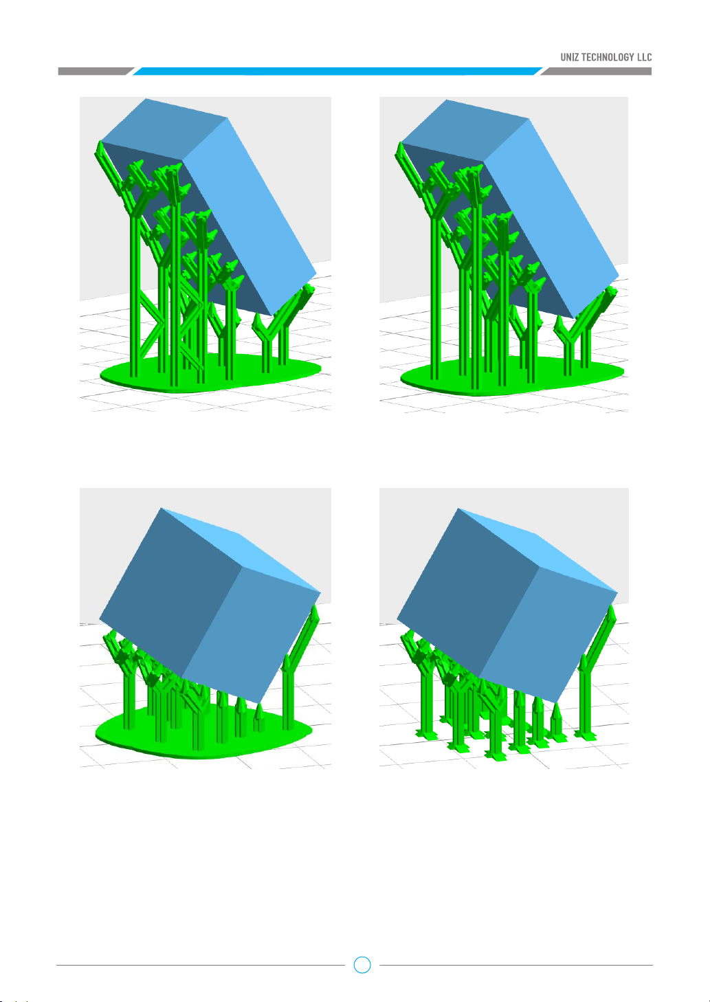
• Connection, Long supports are unstable in structure. Click the connection check box to add
connection parts between long supports for increasing supports stability when generating
supports. The left picture below shows supports with connection and the right one shows
supports without connection. This box is checked by default. Foundation, Click the check box
to add Foundations when generating supports. The left picture below shows supports with
foundation and the right one shows supports without foundation
22
• This box is checked by default. The system will recalculate the foundation when the user
finishes and quit the function of editing supports manually.
• Support Angle, Supports will be generated when the angle between the model part surface
and the horizontal direction is smaller than the support angle, otherwise they will not be
generated. The bigger the support angle is, the wider the scope of generating support. Set this
value to prevent generating supports at steep places and to eliminate unnecessary supports.
You can manually set the angle ranging from 45°to 75°, and the default angle is 60°
• Tilt Angle, To ensure discontinuous exposure in part area under the UDP mode, supports need
to be tilted. Users can manually set the tilt angle ranging from 0°to 20°, and the default angle
is 0°.
23
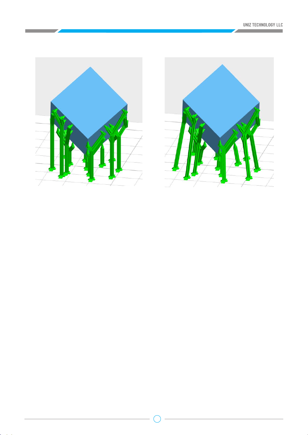
The left picture below is vertical supports and the right is with tilted supports.
• “Lift”: lift the activated object from the build platform upwards by 5mm.
• “Down”: push the activated object down to the build platform.
• “Generate”: generate the support structure using the current settings for all selected models.
• “Edit”: allow the user to manually add, modify, or delete support structures.
• Entry/Exit Manual Edit
Press the “Edit” button, the system enters manual edit support mode. Even if the object is not
selected, you can edit supports manually. Click the “Edit” button again, the system will return to
automatic support mode.
Add Support
Trace the mouse cursor over the model, when your cursor appears as a green line, clicking on the
surface of the model will add a support. If the cursor appears as a red line, it means a support is
not needed.
Modify Support
Click on the surface of the support and, it will be highlighted to indicate that it has been selected.
Once selected, you can drag and drop the support to a target location. If the support turns red
while moving, the position of the support is not ideal and therefore it is not recommended.
You can also change the Support Radius, Header Length, or Point Size sliders to modify support
properties.
Delete Support
Once a support is selected simply press the “DELETE” key to remove it.
24

Tips:
The “Lift”, “Down”, “Generate” buttons are only enabled when a model is being selected.
2.8 Slice
Press the “Slice” Button on the main tool bar and it will open two sub menus, one on the left and
one on the right. The left menu is to start Slice and Show Slices, and the right drag bar and menu is
for customization of slice profile.
a. Slice Parameters
Slice parameters allow users to customize the slice parameters of each segment of a model.
After version 1.2.0 and the upper Desktop sets a separate slider at the third layer by default and
users cannot move this slider in the bar. The Exposure Time of the first three layers will be set
directly in the slice parameter interface rather than in the advanced settings.
Since 1.3.0 version, “Slice Parameters” has been adding “Preference”
and “LED Power”, accordingly “LED Power” will be removed from
“Advanced Settings”. Uniz Desktop will no longer memorize “Exposure
Time”, therefore “Restore” function be abolished. Users can
memorize favorite printing parameters by “Preference”.
25
• “Resin Type” provides different default values for different resin type.
• "Preference": Each resin can define multiple preference to memorize frequently-used printing
parameter, including: Layer Thickness, Exposure Time, Cool Down Time, Pixel Shrink, LED Power,
Motor Speed, Rise Height, Infill, UDP Mode. Right click on button, popup “Preference Editor”
dialog. In “Preference Editor”, click “Add” to create a new preference and click “Remove” to
delete the selected preference. Note: Preference values are obtained directly from the slice
parameters interface and there are not editable; Only the self-defined preference is deletable.
• “Thickness” is the layer thickness, which is related to Z resolution.
• “Exposure Time” is the exposure time of a layer in a particular segment segment, and it may
vary due to a different layer thickness setting or different resin types, i.e. zWax resin takes about
2x exposure time per layer compare to zABS.
• “Cool Down Time” is the time to cool down the exposed layer to protect the polymer film from
overheating. To prolong the lifetime of the resin tank film, it is recommended to keep the film
temperature under 50 degrees Celsius. Overheating the film can cause it to warp, delaminate
and break.
Tips: Avoid exposing the same spot or area over and over; try to orient the model’s walls or pillars in
oblique angle so the exposure area changes on subsequent layers.
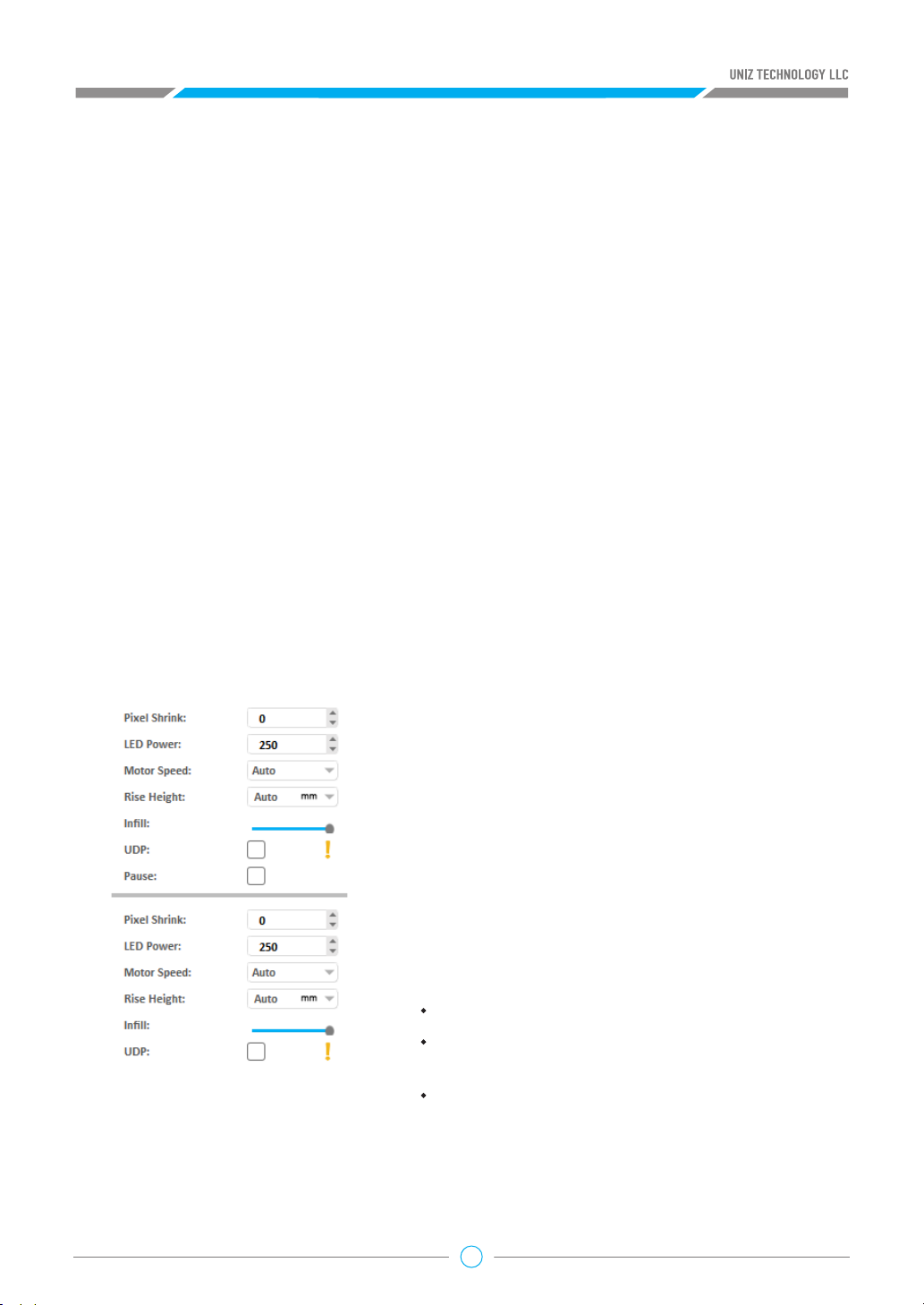
Pressing the “Advanced” Button will open following sub menu.
• “Pixel Shrink”: Shrink or expand the slice polygons.
If value is zero do nothing; If positive shrink slice, if
negative, then expand. The unit is pixels.
• “LED Power” sets the power to the UV LEDS and will
have an impact on curing of the resin Power of LED
module. 150-250 is suggested.
• “Motor Speed” defines the speed of electric motor that
controls the peel motion of the platform.
• “Rise Height” defines the travel height of the peel
motion.
• “Infill”: drag the slider horizontally to modify the infill
ratio ranging from 0% to 100%. The model will be
:
hollowed but not filled when the ratio is 0%;
hollowed and filled by the ratio when the ratio is
among 10% to 90%;
filled but not hollowed when the ratio is 100%;
View the Advanced Settings for the hollowing wall thickness and infill type.
• “UDP” option will be added into the slice parameters when users choose the printers with UDP
function. Users need to check this box when printing UDP model. The Cool Down Time, the
26

Motor Speed and the Rise Height will apply the default value set by the software and they
cannot be modified by the users from the interface.
• “Pause” sets a pre-set pause at the layer of choice during printing, and the pause can be
resumed after pressing the Resume button in the printing control tab.
b. Customize Your Own Z Resolution
By Dividing the model the model into multiple segments and defining different slice parameters, Z
resolution customization can be used to balance print speed and surface quality.
Click the block on the slider bar to start customizing print parameters. The white line shows the
division layer of the two adjacent segments. The upper menu sets the properties of the segment
above the division, and the lower menu sets the properties of the lower segment. You may drag
the slider block to change the division location or double click on blank space on the slider bar to
add another division layer. Press the Delete key when dragging the slider block to erase the division
layer. The last division layer cannot be deleted.
Double click the selected slider and you get a text box. Type layer in the text box and then press
ENTER key to finish and close the editing.
Click the “+” Key to move the slider up one layer incrementally until it reaches the next slider or
the top layer of the model.
Click the “-” Key to move the slider down one layer incrementally until it reaches the next slider.
Notice:
The slider at the bottom (that marks the third layer) does not support operations by the +/button.
Click the “PageUp” Key to select the separate slider above.
Click the “PageDown” Key to select the separate slider below
c. Slice Tools
Click the “Slice” Button to slice all models on the build platform with the defined parameters. The
estimated print information will show in the status bar.
Estimated Time 00:12:40 Volume 17.20ml Layers 57
Click “Show Slices” Button to check any individual layer of the sliced model.
27
You can input a specific layer number in the top right to quickly move to that layer
Drag the right slider vertically to view each layer.
Click the Up/Down arrow to view the previous/next layer incrementally.
If Print When Finished is checked, the sliced data will be sent to the selected printer in the right
bar automatically. The printer still needs confirmation to print via the main button located at the
front of the printer.
Tips:
“Print When Finished” will only be enabled when a printer is connected, the corresponding
Printer Control Panel is open, and the printer is in ready status.
2.9 PRINT
Printer connected via USB will be marked with the icon in the right printing tool bar.
Click the button in the tool bar to search all the printers in the same network . These will be
marked with the icon.
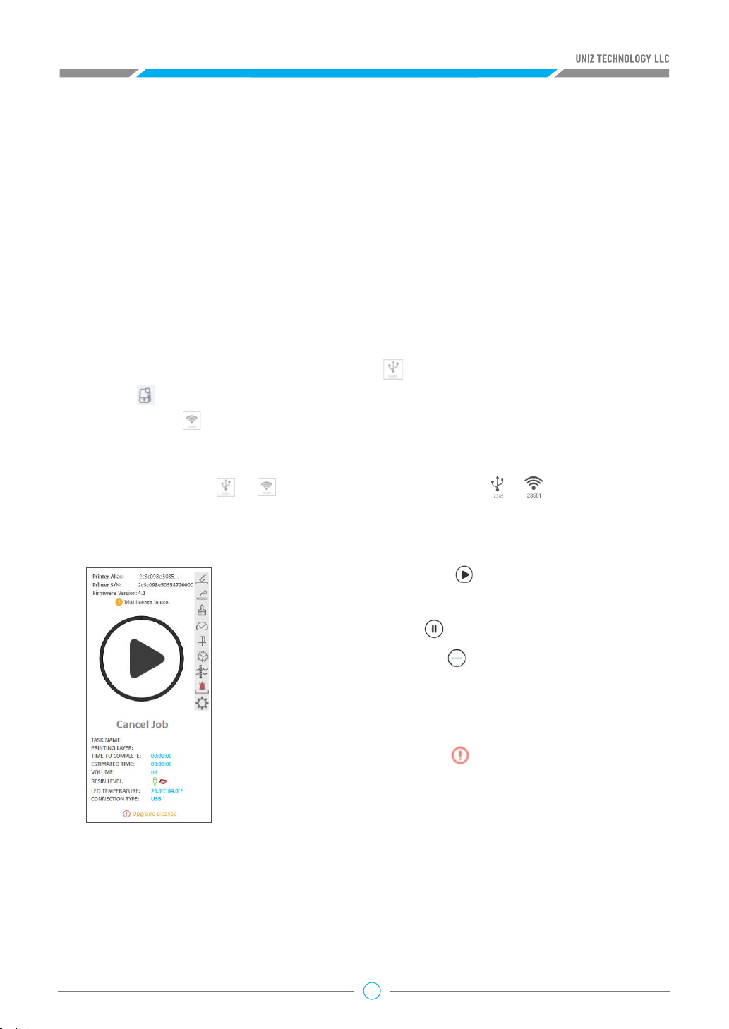
a. Print Tools
Press the printer icon / to open the Printer Control Panel / .The Printer Control
Panel is used to control the printer for printing and regular maintenance. Press the icon the icon to
close the Panel.
Start Job: Click “Start” Button , the system will send the
current slice data to printer and start printing.
Pause Job: Click “Pause “ to suspend a printing job.
Resume Job: Click “Resume” to resume a paused printing job.
Cancel Job: Click “Cancel Job” to cancel the current printing job.
Renaming a Printer: Double clicking the printer name or s/n to
input a new alias and press enter to finish renaming.
Upgrade firmware: An icon “ ” will show next to the firmware
version when there is new version firmware available. Double click
the icon to start upgrading. Restart the printer when the upgrade is
finished.
Fill Resin: Click “Fill” to start pumping resin from the bottle into
the tank. Click again to stop.
Redraw Resin: Click “Redraw” to start redrawing resin from the tank back into the bottle. Click
again to stop.
Full Screen Clean: Click “Clean” to expose the entire screen in order to fully cure and clean the
resin at the bottom of the tank. Debris from previous jobs may damage the LCD screen in the next
job. The Clean function will form an entire resin film entrapping the debris from previous jobs.
28
Once the resin film is removed, the resin tank is clean and ready for the next print job.
TIPS: It is recommended to check the bottom of resin tank before every print job. When there is
debris either floating in the resin or sticking to the bottom of vat, it can damage the LCD.
NOTE: DO NOT remove the resin tank during cleaning exposure. After exposure, however,
you may lift the resin tank to remove the cured resin film.
Show Logo: Show Logo is used to verify if the LCD screen is functional. Before using this function,
remove the build platform and resin tank, then click “Show Logo” Button to show the UNIZ logo on
the LCD screen to test communication and LCD screen.
Reset Z-Axis Zero Position: Reset Z-axis Zero Position is used to re calibrate the vertical motor.
Please remove the resin tank and wipe clean the build platform before using this function. On
the popup box, click “Yes” Button, then push the build platform down manually to touch the LCD
screen. Then click “Yes” again, and the build platform will rise back up.
This function is used if there are issues relating to the initial distance between the build platform
and the screen. This may help with failed prints or adhesion issues.
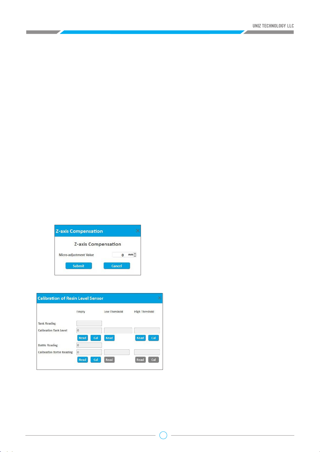
Z-axis Compensation: Enter a value to set a compensation value for the z-axis. This will shorten
the z-axis height from the mechanical calibrated value.
Resin Tank Level Cal
This function is used only when the
printed model is smaller than the
theoretical value along the Z axis
direction. The adjustment value is equal
to the theoretical value minus the actual
value.
Calibration of Resin Level Sensor: Click
“Calibration of Resin Level Sensor”
button to open the dialogue box.
1. Install an empty resin tank and, attach resin sensor to the tank;
2. Calibrate Tank Empty Level: Clicking “Read” and “Cal” button until “Tank Reading” is
29

within ±50.
3. Calibrate Tank Low Threshold: Replace the empty Tank with a Tank filled with 2-3mm resin (or
fill the empty Tank with 2-3mm resin), click “Read” button.
4. Calibrate Tank High Threshold: Replace the Tank with a Tank filled with 7-8mm resin (or fill the
Tank with 7-8mm resin), click “Read “button, and finish the Tank Level Calibration by clicking
“Cal” button.
Calibration of Bottle Resin Level
1. Install an Empty Resin Bottle, and install Resin Level Sensor to the Resin Tank
2. Calibrate Bottle Empty Level: Clicking “Read” and “Cal” button until “Bottle Reading” is within
±50.
3. High/Low threshold is not available in this version.
Auto Pump
1. Click “Auto Pump” Button to turn on / off automatic pumping. If resin level is
too low in the tank and “Auto Pump” is on, the printer will pump resin from the bottle into the
tank automatically.
Printer Settings
Press the “Printer settings” button to popup the submenu including three functions: Network,
Activation,Remote Control, Retime Air Pump and Retime Resin Pump Tube.
1. Network
This shows the printer connection network
status and provides network settings. It supports
automatic and manual IP configuration.
This function only supports setting via USB
connection.
TIP: The Printer's Wi-Fi feature supports 2.4GHz
band only, it does not support 5 GHz connections.
2. Activation
This shows the activation status of the printer. Click to start activating.
3. Remote Control
This shows the remote control status. Users can manually turn on/off the remote control function.
When this function is started for the first time, the system needs to register the printer to the IoT
which may take some time.
4. Air Pump
Display running-time and recommended lifespan of Air Pump. Click right button , it will restart
timer.
30

5. Resin Pump Tube
Display running-time and recommended lifespan of Resin Pump Tube. Click right button , it will
restart timer.
Upgrade License
An icon at the bottom of the printer control panel means this type of printer
can be upgraded. Click the icon to start upgrading the license.
b. Print Process
Send Data to Printer: Click “Start” Button to send the sliced model to the selected printer.
Complete File Transfer: Once you click Start, UNIZ Desktop’s progress bar and the printer’s front
LED circle button will indicate the file transfer progress by lighting in blue.
Confirm Print Job: Make sure that your printer is ready to print and then touch the printer’s front
circular button to confirm print job.
WARNING: Before final confirmation, please make sure the build platform, resin tank, and resin
bottle are installed. Make sure the build platform and resin tank are clear of debris. Make sure the
resin level sensor is properly installed.
After confirmation, you may disconnect your computer from the printer.
Do not disconnect the printer and the software or turn off the UNIZ software during the data
transmission.
2.10 Upload Slice (Optional)
If you want to share your print to the UNIZ Cloud, press the “Upload” Button on the main tools to
open following sub menu.
After your upload completed, you can see the
review progress in Uploaded Models item in
Library. Once the model is approved, the slice
will be displayed on the UniZ store.
31

3. Additional Tools
New Scene: The current scene will be discarded, and a new scene will be created.
Save Scene: Save the current scene in UNIZ file format which includes 3D model data, support
structures, operation history (translation, orientation, scaling), and slice profile. You can load any
saved scene and resume editing at a later time.
Save Scene as: Save current scene to another .UNIZ file.
Advanced Settings:
• “Wall Thickness of Hollowing” sets the
shell thickness of parts hollowed with the
advanced settings in the slice menu.
• “Fill Style” sets the fill style of parts
hollowed with the advanced settings in
the slice menu.
• “Generate Reports”: Tick the left checkbox
to create reports automatically whenyou
start a printing. Click the right button to
modify saving path of reports.
Model List:
Model List provides a modeless dialog for viewing, finding, selecting, hiding, duplicating and
deleting models in 3d scene.
Undo Operation: Undo previous operation.
Redo Operation: Redo a previously undone operation.
32

DESIGN RULES
D
Models Printed in UDP mode must conform to certain design rules in order to print
successfully and prevent damage to the printer. Read more about the design rules at the
link below.
Download link: https://www.uniz.com/support/design_specification
33

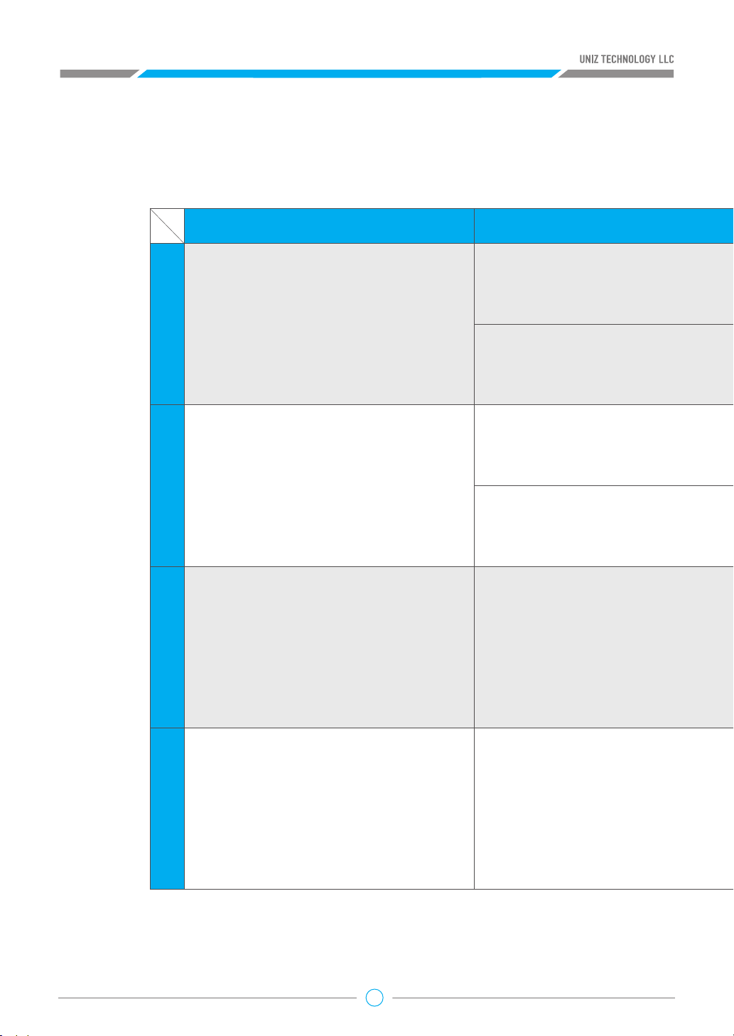
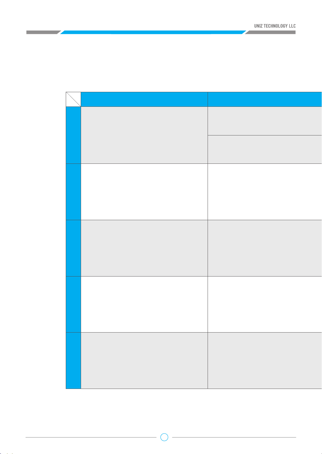
E
Problems Reason Soluons
1
2
3
4
The first layer is not scking correctly
Printed model / layered fault
A stripe of part fail to print
Abnormal LCD performance under
the show logo funcon: no displaying, flickering or different displaying
on le/right side
The calibraon for plaorm inial point is not in
correct posion
Build plaorm surface is too smooth, printed
model falls into the resin tank
The sucon force between the resin tank film and
models is too strong
A row of lights are damaged on the LED light
board
The LCD cable is not inserted properly; damaged
LCD cable
The screen is damaged
Insufficient adhesion between printed layers
TROUBLE SHOOTING
Model with layering
A strip of part fail to print
issues
34

Follow z-axis calibraon procedure and calibrate
again.
Use provided sandpaper to roughen the surface
of the build plaorm and clean up.
Follow the guidance to re-insert or install the
LCD cable.
Follow the guidance to replace the LCD panel.
Return to the factory for repair.
1. Replace with a new resin tank;
2. Remove the resin tank, clean the LCD panel and the boom
of the resin tank film; wipe them with alcohol and then with a
dry paper towel. (Note: touch ONLY the glass part of the screen,
the area covered with black tape should not be touched);
3. Increase cool down me.
Use provided sandpaper to roughen the surface of the build
plaorm and clean up.
Use provided sandpaper to roughen the surface of
the build plaorm and clean up.
35
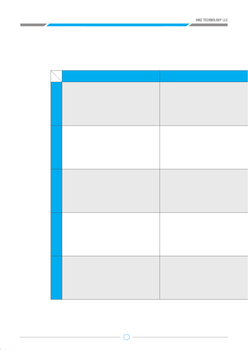
Black spot or black bar appears on the screen
The tension of the resin tank film is not strong
Problems Reason
Problems with supports structures
Solid resin residue on the boom of the build
plaorm causes damage to the resin tank film
Wrinkles on the resin tank film
The model boom is not pressed to the XY plane
5
6
7
Stripy or grainy defects on the
printed model
Edge warp defects on the printed
model
There are wavy lines on the XY plane
enough
ghtly
8
Liquid or solid resin residue appear
on the screen surface
36

Soluons
LCD panel may be over heated. Let it cool or follow
the guidance to replace the LCD panel.
Return to the factory for repair.
Follow the guidance to manually add the supports
Check the first layer slice for any error
Replace with a new resin tank and increase the
cooling me properly for the next print
Replace with a new resin tank and clean the
residual resin on the screen
37
Problems Reason
Resin bole not inserted into the right place
The top vent hole of the resin bole has not
Light-blocking tape is damaged
The boom of the build plaorm and the LCD
There is leak from the liquid cooling system
9
10
11
12
The resin leaks from the right boom
of the printer
Excessive printed part appears. Light
leaks outside the screen display area
Printed model has ripples or wavy
lines on the side face
Oily liquid exuded from the seams
area in front of the label at the print-
er boom, and the level of the liquid
in the coolant tank has significantly
reduced
been pierced
Shaky Z axis
13
Considerable size differences exceeding 1mm among the first several
layers or between the le and the
right of the printer
38
panel are not parallel

Soluons
Clean up the residual resin according to the
guidance and replace with a new resin bole,
make sure the bole is inserted all the way in
Pierce either top hole of the resin bole with the
provided awl
Replace with new tape, cut and cover any exposed
area
Adjust the ghtness of the lead screw nut and the
build plaorm holder according to the guide
Replace with new LCD cooling module or return to
the factory for repair.
Adjust the build plaorm parallelism according to
the tutorial video
39
14
Z-axis limit switch is dysfunconal.
Light-blocking tape is damaged
The fan cable has stuck or the bolt is over
There is poor contact in the circuit
board cable or program error
Problems Reason
The build plaorm could not descend
aer it rises to the highest, with
abnormal sound during the starng
or finishing process of prinng.
15
16
17
18
Automac pumping failed.
Abnormal display appear on the front
light of the printer
Touch problems occur with the front
light of the printer
Abnormal sound can be heard from
the rear cooling fan
The circuit board has broken
ghtened
40

Soluons
Check if the micro switch cable is broken;
return to the factory for repair if it is well
connected
Replace with new tape, cut and cover any
exposed area
Reinsert the cable and restart
Replace with a new circuit board according to
the guidance
Remove the rear fan filter cover and check if
there is any cable interference; adjust the
ghtness of the bolt accordingly
41

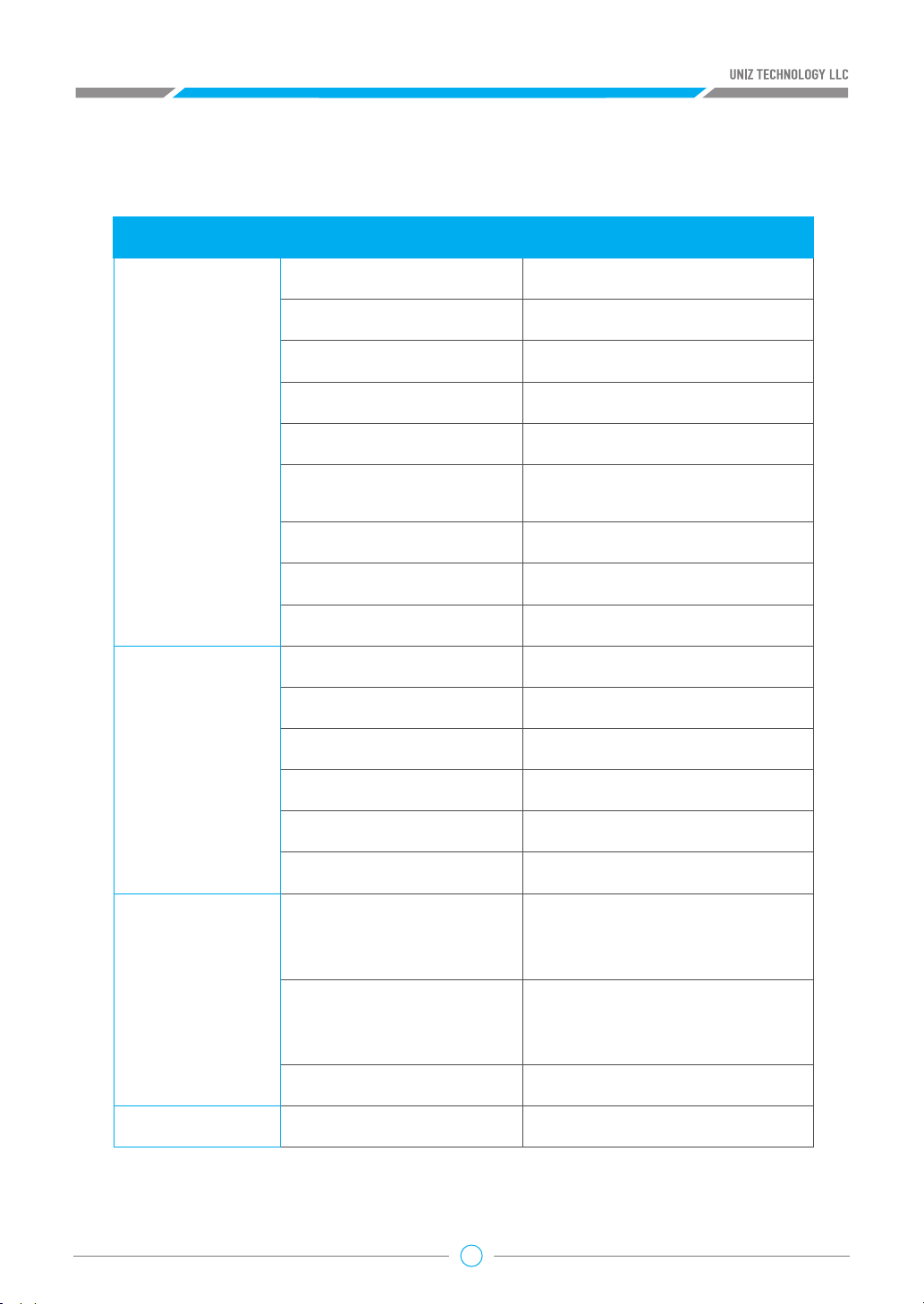
F
ROHS AUTHENTICATION
Hazardous Substance
Pb Hg Cd Cr(VI) PBB (PBDE)
Mainboard
Motor
Column
Power
Fans
Cooling
Board
Resin
Tank
LCD
Board
LED
Board
42

APPENDIX
G
TECHNICAL SPECIFICATIONS
SLASH OL
LCD Stereolithography
192 × 120 × 200mm
7.5" × 4.7" × 7.9"
150μm
±70μm
10, 25, 50, 75, 100, 150, 200, 300μm
10, 25, 50, 100, 150, 200, 300μm
Profile customizable
Profile customizable
Polymer film natural peel
Up to 100x more durable than PDMS
UDP ready**
Uniz smart support technology
Up to 600 mm/hr (UDP mode)
Up to 200 mm/hr (Normal mode)
Automac level control
350 × 400 × 530 mm [W×H×D]
14" × 16" × 21", 14KG/30LB
Prinng
Prinng Technology
Build Volume
XY Resoluon
Highest accuracy**
Layer Thickness(Z resoluon)
Separaon Mechanism
Support
Prinng Speed
Resin Level Control
Dimension/Weight
Operang Temperature
Power Requirement
Hardware
Opcal System
Mechanical
Connecvity
System Requirement
Desktop
Soware
Mobile Apps
*Highest accuracy only achievable at integer multiples of smallest pixel sizes.
**Not applicable to all geometries, UDP specific design rules apply.
Advanced Features
Compable Format
Compable Systems
43
Suggested 18–28° C Suggested 64–82° F
100-240VAC, 6A 50/60Hz
5500 Lux blue LED array
liquid cooling system
Cast Aluminum & CNC, Injecon Molding
USB, Wifi, Ethernet
Windows 7 and up (64-bit only)
Mac OS X 10.7 and up (64-bit only)
16GB RAM, OpenGL 2.1
Discrete Graphics
Mul-printer management
Built-in advanced model repair
Ultra large file support (1GB+)
STL, OBJ, AMF, 3MF, UNIZ
iPhone, iPad, Android Phone and Tablet

SLASH PLUS
Prinng
Hardware
Prinng Technology
Build Volume
XY Resoluon
Highest accuracy**
Layer Thickness(Z resoluon)
Separaon Mechanism
Support
Prinng Speed
Resin Level Control
Dimension/Weight
Operang Temperature
Power Requirement
Opcal System
LCD Stereolithography
192 × 120 × 200mm
7.5" × 4.7" × 7.9"
75μm
±20μm
10, 25, 50, 100, 150, 200, 300μm
10, 25, 50, 75, 100, 150, 200, 300μm
Profile customizable
Profile customizable
Polymer film natural peel
Up to 100x more durable than PDMS
Uniz smart support technology
Up to 200 mm/hr
Automac level control
350 × 400 × 530 mm [W×H×D]
14" × 16" × 21", 14KG/30LB
Suggested 18–28° C Suggested 64–82° F
100-240VAC, 6A 50/60Hz
5500 Lux blue LED array
liquid cooling system
Mechanical
Connecvity
System Requirement
Desktop
Soware
Advanced Features
Compable Format
Mobile Apps
*Highest accuracy only achievable at integer multiples of smallest pixel sizes.
Compable Systems
44
Cast Aluminum & CNC, Injecon Molding
USB, Wifi, Ethernet
Windows 7 and up (64-bit only)
Mac OS X 10.7 and up (64-bit only)
16GB RAM, OpenGL 2.1
Discrete Graphics
Mul-printer management
Built-in advanced model repair
Ultra large file support (1GB+)
STL, OBJ, AMF, 3MF, UNIZ
iPhone, iPad, Android Phone and Tablet
Prinng
Hardware
Desktop
Soware
Mobile Apps
Operang Temperature
Power Requirement
Opcal System
Dimension/Weight
Prinng Technology
XY Resoluon
Build Volume
Separaon Mechanism
Support
Highest accuracy**
Prinng Speed
Resin Level Control
Mechanical
Layer Thickness(Z resoluon)
Connecvity
System Requirement
Advanced Features
Compable Format
Compable Systems
Suggested 18–28° C Suggested 64–82° F
100-240VAC, 6A 50/60Hz
5500 Lux blue LED array
liquid cooling system
Uniz smart support technology
350 × 400 × 530 mm [W×H×D]
14" × 16" × 21", 14KG/30LB
LCD Stereolithography
75μm
192 × 120 × 200mm
7.5" × 4.7" × 7.9"
Polymer film natural peel
Up to 100x more durable than PDMS
UDP ready**
±20μm
Up to 600 mm/hr (UDP mode)
Up to 200 mm/hr (Normal mode)
Automac level control
10, 25, 50, 100, 150, 200, 300μm
Profile customizable
Cast Aluminum & CNC, Injecon Molding
USB, Wifi, Ethernet
Windows 7 and up (64-bit only)
Mac OS X 10.7 and up (64-bit only)
16GB RAM, OpenGL 2.1
Discrete Graphics
Mul-printer management
Built-in advanced model repair
Ultra large file support (1GB+)
STL, OBJ, AMF, 3MF, UNIZ
iPhone, iPad, Android Phone and Tablet
SLASH PLUS UDP
10, 25, 50, 75, 100, 150, 200, 300μm
Profile customizable
*Highest accuracy only achievable at integer multiples of smallest pixel sizes.
**Not applicable to all geometries, UDP specific design rules apply.
45

Prinng
Hardware
Desktop
Soware
Mobile Apps
Operang Temperature
Power Requirement
Opcal System
Dimension/Weight
Prinng Technology
XY Resoluon
Build Volume
Separaon Mechanism
Support
Highest accuracy**
Prinng Speed
Resin Level Control
Mechanical
Layer Thickness(Z resoluon)
Connecvity
System Requirement
Advanced Features
Compable Format
Compable Systems
Suggested 18–28° C Suggested 64–82° F
100-240VAC, 6A 50/60Hz
5500 Lux blue LED array
liquid cooling system
Uniz smart support technology
350 × 400 × 730 mm [W×H×D]
14" × 16" × 29", 14KG/30LB
LCD Stereolithography
150μm
192 × 120 × 400mm
7.5" × 4.7" × 7.9"
Polymer film natural pee
Up to 100x more durable than PDMS
UDP ready**
±70μm
Up to 600 mm/hr (UDP mode)
Up to 200 mm/hr (Normal mode)
Automac level control
10, 25, 50, 100, 150, 200, 300μm
Profile customizable
Cast Aluminum & CNC, Injecon Molding
USB, Wifi, Ethernet
Windows 7 and up (64-bit only)
Mac OS X 10.7 and up (64-bit only)
16GB RAM, OpenGL 2.1
Discrete Graphics
Mul-printer management
Built-in advanced model repair
Ultra large file support (1GB+)
STL, OBJ, AMF, 3MF, UNIZ
iPhone, iPad, Android Phone and Tablet
SLASH PRO OL
10, 25, 50, 75, 100, 150, 200, 300μm
Profile customizable
*Highest accuracy only achievable at integer multiples of smallest pixel sizes.
**Not applicable to all geometries, UDP specific design rules apply.
46

SLASH PRO
Prinng
Hardware
Prinng Technology
Build Volume
XY Resoluon
Highest accuracy**
Layer Thickness(Z resoluon)
Separaon Mechanism
Support
Prinng Speed
Resin Level Control
Dimension/Weight
Operang Temperature
Power Requirement
Opcal System
LCD Stereolithography
192 × 120 × 400mm
7.5" × 4.7" × 15.8"
75μm
±20μm
10, 25, 50, 75, 100, 150, 200, 300μm
10, 25, 50, 100, 150, 200, 300μm
Profile customizable
Profile customizable
Polymer film natural peel
Up to 100x more durable than PDMS
Uniz smart support technology
Up to 200 mm/hr
Automac level control
350 × 400 × 730 mm [W×H×D]
14" × 16" × 29", 18KG/40LB
Suggested 18–28° C Suggested 64–82° F
100-240VAC, 6A 50/60Hz
5500 Lux blue LED array
liquid cooling system
Mechanical
Connecvity
System Requirement
Desktop
Soware
Advanced Features
Compable Format
Mobile Apps
*Highest accuracy only achievable at integer multiples of smallest pixel sizes.
Compable Systems
47
Cast Aluminum & CNC, Injecon Molding
USB, Wifi, Ethernet
Windows 7 and up (64-bit only)
Mac OS X 10.7 and up (64-bit only)
16GB RAM, OpenGL 2.1
Discrete Graphics
Mul-printer management
Built-in advanced model repair
Ultra large file support (1GB+)
STL, OBJ, AMF, 3MF, UNIZ
iPhone, iPad, Android Phone and Tablet

Prinng
Hardware
Desktop
Soware
Mobile Apps
Operang Temperature
Power Requirement
Opcal System
Dimension/Weight
Prinng Technology
XY Resoluon
Build Volume
Separaon Mechanism
Support
Highest accuracy**
Prinng Speed
Resin Level Control
Mechanical
Layer Thickness(Z resoluon)
Connecvity
System Requirement
Advanced Features
Compable Format
Compable Systems
Suggested 18–28° C Suggested 64–82° F
100-240VAC, 6A 50/60Hz
5500 Lux blue LED array
liquid cooling system
Uniz smart support technology
350 × 400 × 730 mm [W×H×D]
14" × 16" × 29", 18KG/40LB
LCD Stereolithography
75μm
192 × 120 × 400mm
7.5" × 4.7" × 15.8"
Polymer film natural peel
Up to 100x more durable than PDMS
UDP ready**
±20μm
Up to 600 mm/hr (UDP mode)
Up to 200 mm/hr (Normal mode)
Automac level control
10, 25, 50, 100, 150, 200, 300μm
Profile customizable
Cast Aluminum & CNC, Injecon Molding
USB, Wifi, Ethernet
Windows 7 and up (64-bit only)
Mac OS X 10.7 and up (64-bit only)
16GB RAM, OpenGL 2.1
Discrete Graphics
Mul-printer management
Built-in advanced model repair
Ultra large file support (1GB+)
STL, OBJ, AMF, 3MF, UNIZ
iPhone, iPad, Android Phone and Tablet
SLASH PRO UDP
10, 25, 50, 75, 100, 150, 200, 300μm
Profile customizable
*Highest accuracy only achievable at integer multiples of smallest pixel sizes.
**Not applicable to all geometries, UDP specific design rules apply.
48

Prinng
Hardware
Desktop
Soware
Mobile Apps
Operang Temperature
Power Requirement
Opcal System
Dimension/Weight
Prinng Technology
XY Resoluon
Build Volume
Separaon Mechanism
Support
Highest accuracy**
Prinng Speed
Resin Level Control
Mechanical
Layer Thickness(Z resoluon)
Connecvity
System Requirement
Advanced Features
Compable Format
Compable Systems
* Equipped with two LCD modules, outpung the same slices.
* * Highest accuracy only achievable at integer mulples of smallest pixel sizes
Suggested 18–28° C Suggested 64–82° F
100-240VAC, 6A 50/60Hz
5500 Lux blue LED array
liquid cooling system
Uniz smart support technology
350 × 400 × 530 mm [W×H×D]
14" × 16" × 21", 14KG/30LB
LCD Stereolithography
47μm
Duo LCD*, 120 × 68 × 200mm
4.76" × 2.67" × 7.9"
Polymer film natural peel
Up to 100x more durable than PDMS
±10μm
Up to 200 mm/hr
Automac level control
10, 25, 50, 75, 100, 150, 200, 300μm
Profile customizable
Cast Aluminum & CNC, Injecon Molding
USB, Wifi, Ethernet
Windows 7 and up (64-bit only)
Mac OS X 10.7 and up (64-bit only)
16GB RAM, OpenGL 2.1
Discrete Graphics
Mul-printer management
Built-in advanced model repair
Ultra large file support (1GB+)
STL, OBJ, AMF, 3MF, UNIZ
iPhone, iPad, Android Phone and Tablet
SLASH DJ2
10, 25, 50, 75, 100, 150, 200, 300μm
Profile customizable
49

Prinng
Hardware
Desktop
Soware
Mobile Apps
Operang Temperature
Power Requirement
Opcal System
Dimension/Weight
Prinng Technology
XY Resoluon
Build Volume
Separaon Mechanism
Support
Highest accuracy**
Prinng Speed
Resin Level Control
Mechanical
Layer Thickness(Z resoluon)
Connecvity
System Requirement
Advanced Features
Compable Format
Compable Systems
Suggested 18–28° C Suggested 64–82° F
100-240VAC, 6A 50/60Hz
5500 Lux blue LED array
liquid cooling system
Uniz smart support technology
350 × 400 × 530 mm [W×H×D]
14" × 16" × 21", 14KG/30LB
LCD Stereolithography
47μm
120 × 68 × 200mm
4.76" × 2.67" × 7.9"
Polymer film natural peel
Up to 100x more durable than PDMS
±10μm
Up to 600 mm/hr (UDP mode)
Up to 200 mm/hr (Normal mode)
Automac level control
10, 25, 50, 100, 150, 200, 300μm
Profile customizable
Cast Aluminum & CNC, Injecon Molding
USB, Wifi, Ethernet
Windows 7 and up (64-bit only)
Mac OS X 10.7 and up (64-bit only)
16GB RAM, OpenGL 2.1
Discrete Graphics
Mul-printer management
Built-in advanced model repair
Ultra large file support (1GB+)
STL, OBJ, AMF, 3MF, UNIZ
iPhone, iPad, Android Phone and Tablet
SLASH J UDP
10, 25, 50, 75, 100, 150, 200, 300μm
Profile customizable
* Highest accuracy only achievable at integer multiples of smallest pixel sizes
50

 Loading...