

Unix CCTV PT 980 User Manual
User’s Manual
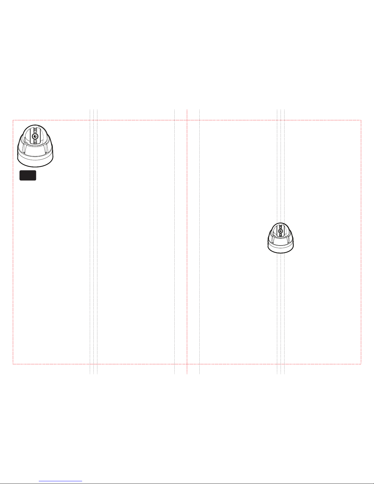
Speed Dome Camera
Anti-vandal
x
10
2 3
Safety Information
x10 Anti-vandal
Speed Dome Camera
User’s Manual
Ver. 3 . 1 / 2009.09
This symbol indicates that dangerous voltage
consisting a risk of electric shock is present within
this unit.
Warning Precaution
This exclamation point symbol is intended to alert the
user to the presence of important operating and
maintenance (servicing) instructions in the literature
accompanying the appliance.
TO REDUCE THE RISK OF ELECTRIC SHOCK, DO NOT REMOVE COVER (OR BACK) NO USER SERVICEABLE
PARTS INSIDE. REFER SERVICING TO QUALIFIED SERVICE PERSONNEL.
CAUTION
:
CAUTION
RISK OF ELECTRIC SHOCK.
DO NOT OPEN.
To prevent damage which may result in fire or electric shock hazard, do not expose this appliance to rain or moisture.
1. Be sure to use only the standard adapter that is specified in the specification sheet. Using any other adapter could
cause fire, electrical shock, or damage to the product.
2. Incorrectly connecting the power supply or replacing battery may cause explosion, fire, electric shock, or damage
to the product.
3. Do not connect multiple cameras to a single adapter. Exceeding the capacity may cause abnormal heat generation
or fire.
4. Securely plug the power cord into the power receptacle. Insecure connection may cause fire.
5. When installing the camera, fasten it securely and firmly. A falling camera may cause personal injury.
6. Do not place conductive objects (e.g. screw drivers, coins, metal things, etc.) or containers filled with water on top
of the camera. Doing so may cause personal injury due to fire, electric shock, or falling objects.
7. Do not install the unit in humid, dusty, or sooty locations. Doing so may cause fire or electric shock.
8. If any unusual smells or smoke come from the unit, stop using the product. In such case, immediately disconnect
the power source and contact the service center. Continued use in such a condition may cause fire or electric shock.
9. If this product fails to operate normally, contact the nearest service center. Never disassemble or modify this
product in any way.
10. When cleaning, do not spray water directly onto parts of the product. Doing so may cause fire or electric shock.
WARNING
WARNING

Precautions Contents
4 5
67Product & Accessories
Parts Name & Functions
4 Precation
1. Introduction
8
10
11
12
13
14
16
17
DIP Switch Setup
Installation Using Surface Mount Bracket
Installation Using Flush Mount Ring Bracket(Option)
Installation Using Ceiling Mount Bracket(Option)
Installation Using Wall Mount Bracket(Option)
Installation Using Wall Mount Bracket with Junction Box(Option)
Cabling the 5P Terminal Block
Cabling the 7P Terminal Block
2. Installation
18
19
20
21
22
24
25
26
28
30
31
32
34
36
37
38
40
Check Points before Operation
Main Functions
OSD Information
General Rules of Menu Operation
OSD Menu Contents
OSD -
ROOT MENU & SYSTEM INFORMATION
OSD -
DISPLAY SETUP
OSD -
MOTION SETUP
OSD -
FUNCTION SETUP>PRESET SETUP
OSD -
FUNCTION SETUP>SCAN SETUP
OSD -
FUNCTION SETUP>PATTERN SETUP
OSD -
FUNCTION SETUP>GROUP SETUP
OSD -
FUNCTION SETUP>SCHEDULE SETUP
OSD -
CAMRA SETUP>WB SETUP
OSD -
CAMRA SETUP>AE SETUP
OSD -
SYSTEM SETUP
OSD -
SYSTEM INITIALIZE
3. OSD Menu
41
42
44
Dimensions
Dimensions of Option Brackets
Specifications
4. Specification
Operating
Before using, make sure power supply and others are properly connected.
While operating, if any abnormal condition or malfunction is observed, stop using the camera immediately and then
contact your Special dealer.
Handling
Do not disassemble or tamper with parts inside the camera.
Do not drop or subject the camera to shock and vibration as this can damage camera.
Care must be taken when you clean the clear dome cover. Especially, scratch and dust will ruin your quality of camera.
Installation and Storage
Do not install the camera in areas of extreme temperature, which exceed the allowable range.
Avoid installing in humid or dusty places.
Avoid installing in places where radiation is present.
Avoid installing in places where there are strong magnetic elds and electric signals.
Avoid installing in places where the camera would be subject to strong vibrations.
Never expose the camera to rain and water.
Product & Accessories Parts Name & Functions
1
6 7
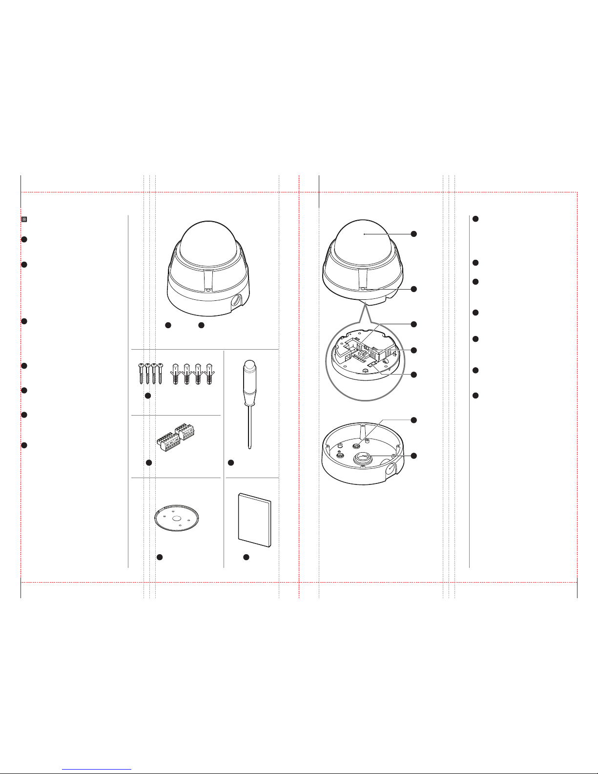
Main Body
Main Body + Surface Mount Bracket
1
2
1
Terminal Block x2: 5P+7P
4
Rubber Gasket
6
Screw & Plastic Anchor-4pcs
3
Manual
7
User’s Manual
Surface Mount Bracket
2
Camera module, screws, terminal block slot and
DIP switches are included.
- It is used when installing the camera right on to
the ceiling.
- To install the camera with the surface mount
bracket, the bracket needs to be separated from
the main body, then needs to be re-assembled
the bracket and the main body according to the
order.
Terminal Block
4
Power, video, communication and alarm input
cables are connected through the terminal blocks.
Torx Screw Driver
5
It is used to screw/unscrew the fixed screws on
the main body.
Rubber Gasket
6
Manual
7
Please read the manual carefully before installing.
It is installed between the surface mount bracket
and wall/wall mount bracket to prevent the water
leakage.
Screw & Plastic Anchor
3
- Screws are used to fix the surface mount bracket
to the ceiling.
- Plastic anchors are used to tighten the screws to
the hole by inserting them into the holes in
advance.
Please check if all the camera and
accessories are included in the package.
Torx Screw Driver
5
Main Body
Dome Cover
1
Lockup Screw
2
Surface Mount Bracket
Bottom of Main Body
Dome Cover
1
- Protects the camera module from outside
environment.
- Do not detach protection vinyl from the dome
cover before finishing all installation processes
to protect dome cover from scratches or dust.
Lockup Screw
2
Fixes main body to the surface mount bracket.
7P Terminal Block Slot
3
- Power, keyboard controller/DVR video device are
connected to this terminal block.
- Refer page 17 for details.
DIP Switch
4
- Adjusts camera ID and protocols.
- Refer page 8, 9 for details.
5P Terminal Block Slot
5
- Alarm input and relay out cables are connected to
this terminal block.
- Refer page 16 for details.
Mounting Hole
6
This is used to attach the surface mount bracket
to the ceiling.
¾” Pipe Mounting Hole
7
- This is used to pass the cables to the cameras.
- When water protection is needed, connect the
¾” pipe through this hole, then pass the cables
through the pipe.
5P Terminal Block Slot
5
7P Terminal Block Slot
3
DIP Switch
4
Mounting Hole
6
¾” Pipe Mounting Hole
7
DIP Switch Setup DIP Switch Setup
2
8 9
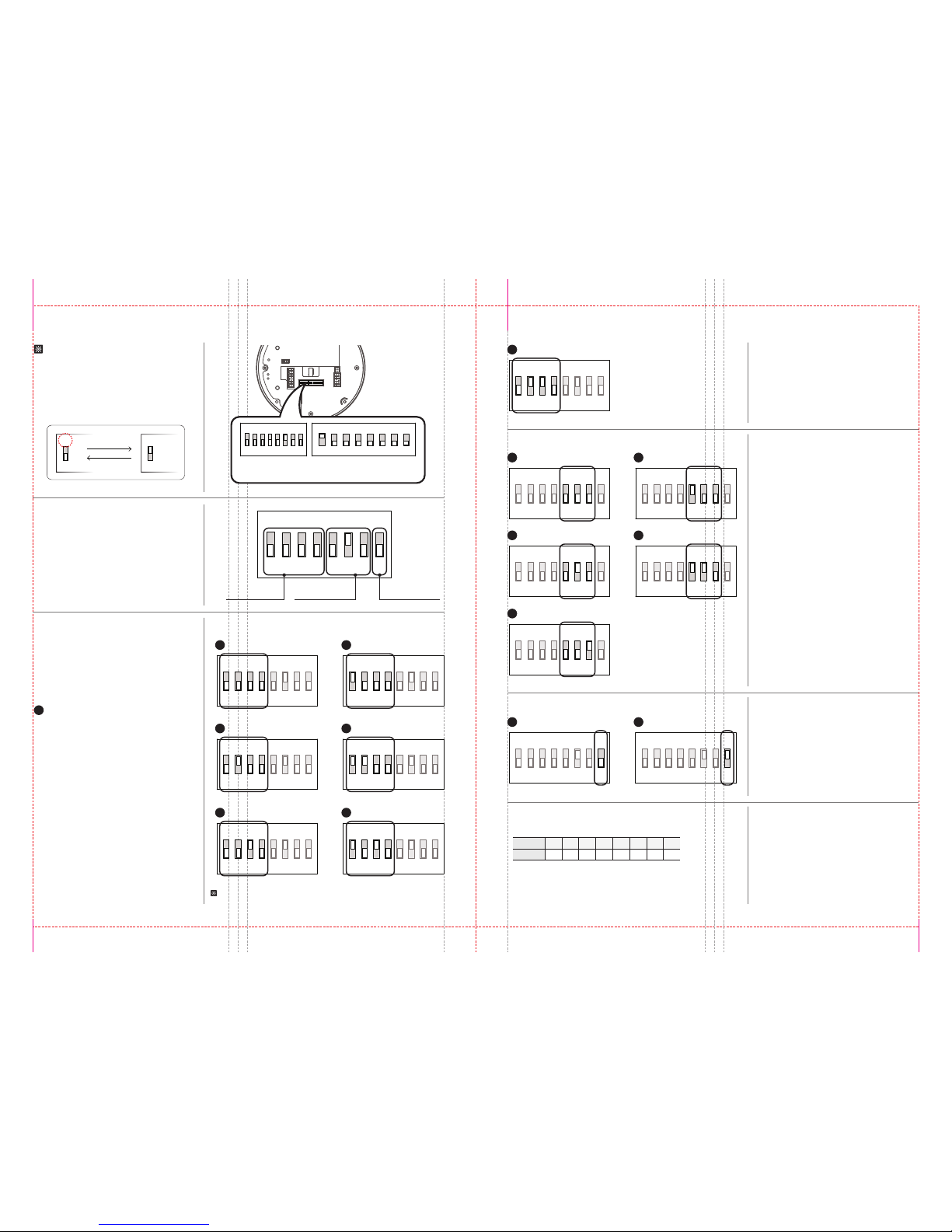
Choose the appropriate baud rate protocol by setting the DIP switch
Choose the termination resistor on/off to notify the last camera.
ON
21 3 4 5 6 7 8
ON
21 3 4 5 6 7 8
ON
21 3 4 5 6 7 8
ON
21 3 4 5 6 7 8
2400 BPS
1
4800 BPS
2
9600 BPS
3
19200 BPS
4
ON
21 3 4 5 6 7 8
38400 BPS
5
ON
21 3 4 5 6 7 8
Normal
1
ON
21 3 4 5 6 7 8
Last Camera
2
Camera ID Setup
- ID number of camera is set using binary number. The example is shown below.
Pin 1 2 3 4 5 6 7 8
1 2 4 8 16 32 64 128ID Value
- Select the appropriate baud rate with DIP switch
combination.
- The factory default is 9600BPS.
3. Baud Rate Setup
- If you want to control a certain camera, you must
match the camera ID with ‘CAM ID, setting of DVR
or keyboard controller.
-
ID number of the camera is set using binary number.
-
The range of ID is 0~255.
Factory default of
camera ID is 1.
- Camera ID will be effective without rebooting
the camera.
5. DIP Switch for Camera ID Setup
- Pin 8 is use for on/off of RS-485 termination.
Normally, it must be off state.
-
Especially, when you have trouble with long daisy
chain style connection, turn on this termination
switch of the last camera.
4. RS-485 Termination Setup
Auto Protocol
1
Communication
Protocol Setup Pin Baud Rate Setup Pin
RS-485 Termination
Setup Pin
Auto Protocol
1
- If you set the protocol as auto protocol, camera will
automatically recognize the kind of protocol.
Pin On/Off
If the pin is located ‘ON’ side of the printed
label, it means on. In reverse, means off.
Pin On
Pin Off
Before installing the camera, you should
set the DIP switch to configure the camera
ID, communication protocol.
Choose the appropriate communication protocol by setting the DIP switch.
ON
21 3 4 5 6 7 8
ON
21 3 4 5 6 7 8
PELCO-D
2
ON
21 3 4 5 6 7 8
PELCO-P
3
ON
21 3 4 5 6 7 8
SAMSUNG
4
ON
21 3 4 5 6 7 8
Bottom of Main Body
ON
1
ON
1
If there is other combination of pins from above, it will be recognize as
auto protocol.
ON
21 3 4 5 6 7 8
ON
8J
21 3 4 5 6 7 8
DIP Switch for
Communication
DIP Switch for
Camera ID Setup
AD(American Dynamics)
7
ON
21 3 4 5 6 7 8
- It is consist of communication protocol, baud rate
and RS-485 termination setup pins.
- If you change the camera protocol by changing
the DIP switch, the change will be eective after
rebooting the camera.
1. DIP Switch for Communication
- If you want to control using DVR or keyboard
controller, their protocol must be identical to the
camera’s protocol. Otherwise, you cannot control
the camera.
- The factory default is auto protocol.
2. Communication Protocol Setup
2. Communication Protocol Setup
Panasonic
5
ON
21 3 4 5 6 7 8
GE(Kalatel)
6
ON
21 3 4 5 6 7 8
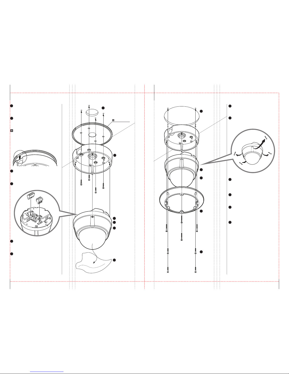
Installation Using Surface Mount Bracket Installation Using Flush Mount Ring Bracket (Option)
2
10 11
Drilling the Hole on the Ceiling
1
Fix the Main Body
5
Connect the
Terminal Blocks
4
Connect the Cables
3
Detach the
Protection Vinyl
6
Drilling the Hole on the Ceiling
To pass cables through the ceiling, drill a hole
(30mm diameter) on the ceiling panel.
Pass the cables to the ¾” pipe hole, and screw
the surface mount bracket to the ceiling.
Fix the Main Body
5
Screw the main body to the surface mount bracket
by screwing 4 lock-up screws.
Detach the Protection Vinyl
6
Detach the protection vinyl from the dome cover.
Detach the Protection Vinyl
6
Detach the protection vinyl from the dome cover.
Fix the Surface
Mount Bracket
2
1
Fix the Surface Mount Bracket
Rubber Gasket
2
Rubber Gasket
Connect the Terminal Blocks
4
Connect the terminal blocks to the main body.
Connect the Cables
3
- Connect wire cables to the terminal blocks.
- Refer page 16, 17 for details.
- Before installing the gasket, the hole in the center
is to be cut by knife when only necessary.
- When installing gasket, the protrusion of the
gasket should be matched with the groove joint
of the bottom of the surface mount bracket.
Fix the Main Body
5
Fix the Flush Mount
Ring Bracket to the
Main Body
3
Drilling the Hole on the Ceiling
1
To pass cables through the ceiling, drill a
hole(70mm diameter) on the ceiling.
Separate the Lock-up Screws from the
Main Body
2
Separate the 4 lock-up screws from the main body
in advance.
Fix the Flush Mount Ring Bracket to the
Main Body
3
Fix the flush mount ring bracket to the main body
using torx screws.
Fix the Main Body
5
Screw the main body with the surface mount
bracket to the ceiling using the screws on the
surface mount bracket.
Connect Wire the Cables and Terminal Blocks
4
Connect wire cables to the terminal blocks.
Refer page 16, 17 for details.
Separate the Lock-up
Screws from the Main
Body
2
Wire the Cables and
Terminal Blocks
4
Drilling the Hole
on the Ceiling
1
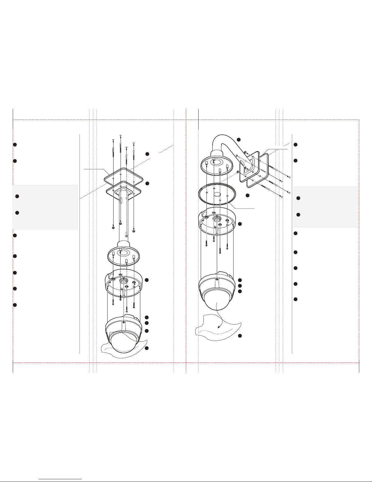
Installation Using Ceiling Mount Bracket (Option) Installation Using Wall Mount Bracket (Option)
2
12 13
Fix the Main Body
7
Connect the
Terminal Blocks
Wire Cables
4
Fix the Surface
Mount Bracket
Detach the
Protection Vinyl
Drill the Ceiling and Fix the Anchor Bolts
1
Fix the Ceiling Mount Bracket
2
On the ceiling, drill a hole (6mm diameter/ 50mm
depth), and fix the anchor bolts.
1. Drill a hole (20mm diameter) on the pipe of the
bracket to pass the cables.
2. On the fixed anchor bolts, attach the rubber
gasket and screw the ceiling mount bracket.
Fix the Wall Mount Bracket
1. Drill a hole (20mm diameter) on the pipe of the
bracket to pass the cables.
2. On the fixed anchor bolts, attach the rubber
gasket and fix the wall mount bracket with nuts
and screws.
Fix the Surface Mount Bracket
3
Pass the cables through the hole of the surface
mount bracket, screw the surface mount bracket
to the ceiling mount bracket.
Connect the Terminal Blocks
5
Connect terminal block to the main body.
Refer page 10.
Fix the Main Body
6
Screw the main body to the surface mount bracket.
(Screws are included in the main body.)
Detach the Protection Vinyl
7
Detach the protection vinyl from the dome cover.
Wire Cables
4
Wire the cables to the terminal block.
Refer page 16, 17.
Fix the Surface Mount Bracket
Pass the cables through the hole of the surface
mount bracket, screw the surface mount bracket
to the wall mount bracket.
Connect the Terminal Blocks
Connect terminal block to the main body.
Refer page 10.
Fix the Main Body
Screw the main body to the surface mount bracket.
(Screw are included in the main body.)
Detach the Protection Vinyl
Detach the protection vinyl from the dome cover.
Wire Cables
Wire the cables to the terminal block.
Refer page 16, 17.
Fix the Ceiling
Mount Bracket
Rubber Gasket
Rubber Gasket
Drill the Wall and
Fix the Anchor Bolts
1
2
3
3
6
5
Fix the Main Body
Connect the Terminal Blocks
Wire Cables
4
6
5
Drill the Ceiling and
Fix the Anchor Bolts
1
Fix the Surface Mount Bracket
Detach the Protection Vinyl
7
Fix the Wall Mount Bracket
1. Installing on the Concrete Ceiling 1. Installing on the Concrete Wall
Drill the Ceiling
1
Fix the Ceiling Mount Bracket
2
To pass cables to upside of ceiling, drill a hole
(30mm diameter) on the ceiling.
Pass the cables into the ceiling mount bracket,
and screw the ceiling mount bracket to the
ceiling.
2. Installing on the Wooden Ceiling
Drill the Wall
Fix the Wall Mount Bracket
Drill the Wall and Fix the Anchor Bolts
On the wall, drill a hole (6mm diameter/50mm
depth), and fix the anchor bolts.
1
2
3
5
6
7
4
1
2
To pass cables to the wall, make a hole about
30 mm on the wall.
Pass the cables into the wall mount bracket,
and screw the wall mount bracket to the wall.
2. Installing on the Wooden Wall
2
Rubber Gasket
 Loading...