


Welcome to the Notebook PC
Thank you for purchasing your new notebook. Your Notebook features the latest advances in
portable computing technology. Your new notebook will meet your computing needs both today
and in the future with modular design provides maximum expandability without compromising
portability.
There are a wide range of wireless home entertainment and networking products to experience
digital entertainment in a truly connected home without the need for messy cables and wiring.
USING THE USER GUIDE
N
O
I
T
C
U
D
O
R
T
N
I
I
I
N
N
T
T
R
R
O
O
D
D
U
U
C
C
T
T
I
I
O
O
N
N
This user guide has been designed to explain all of the important features and functions of your
new notebook and the Microsoft Windows XP Home Edition operating system.
1
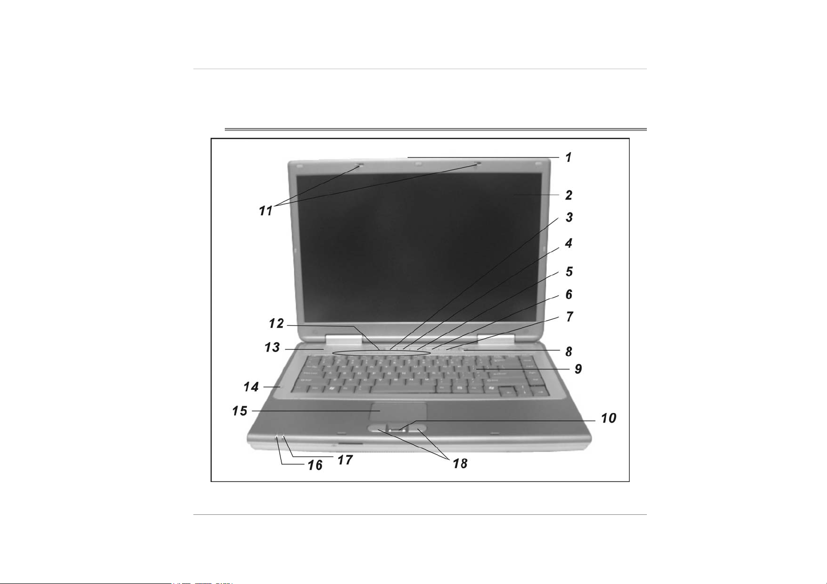
System At A Glance
RONT VIEW
F
2
1. LCD LATCH
The LCD latch unlock the LCD panel.
2. KEYBOARD
The keyboard is used to enter data. It has an embedded numeric keypad and
cursor control keys.
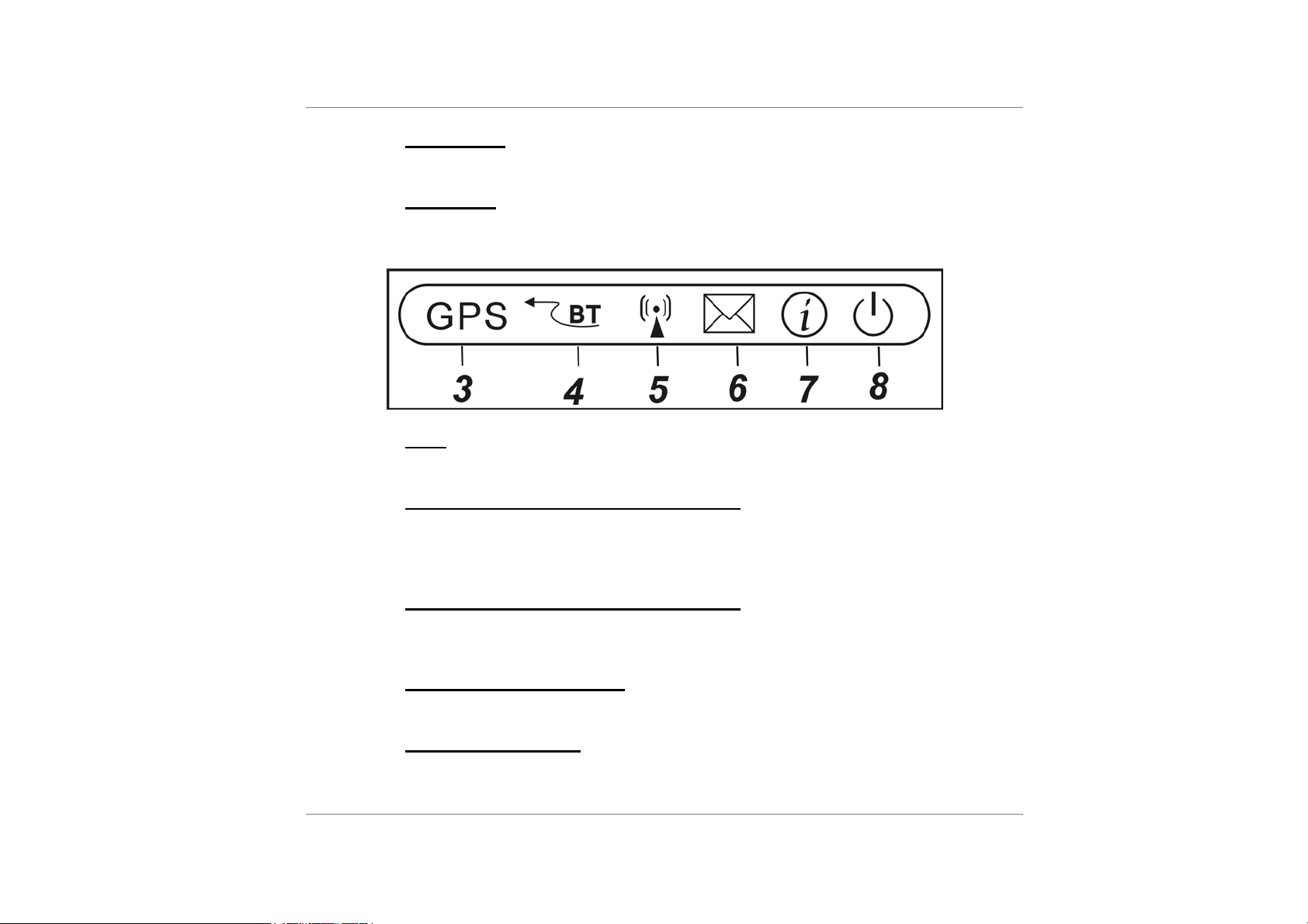
3.
GPS
GPS (Global Positioning Service)
4. WIRELESS AND BLUETOOTH ON/OFF KEY
Press the On/Off key repeatedly to select one or both of wireless and Bluetooth
to enable or disable. When Wireless icon (key top) appears green, the wireless
LAN function is enabled.
5. WIRELESS AND BLUETOOTH ON/OFF KEY
Press the On/Off key repeatedly to select one or both of wireless and Bluetooth
to enable or disable.
6. MICROSOFT OUTLOOK KEY
Press this key to open the Microsoft Outlook to receive and send mail.
7. INTERNET QUICK KEY
The Internet Quick Key launches the Internet Explore.
3
8. POWER BUTTON
The power button turns the notebook on and off. Press momentarily to turn on the
system. Press and hold for at least 3~4 seconds to turn off the system. How this
key behaves can be defined in [Start > Settings > Control Panel > Power Options
> Advanced] menu.
9. KEYBOARD
The keyboard is used to enter data. It has an embedded numeric keypad and
cursor control keys. (See Keyboard Section for details.)
10. OPTICAL FINGERPRINT READER
Place your finger gently on the glass window and slide your finger from top to
bottom. You will need to use this security feature with an application.
11. LCD LATCH
The LCD latch locks the LCD panel.
12. LED STATUS INDICATOR
The LED Status Indicator displays the operating status of your notebook. When a
certain function is enabled, an LED will light up. The following section describes
its indication.
4
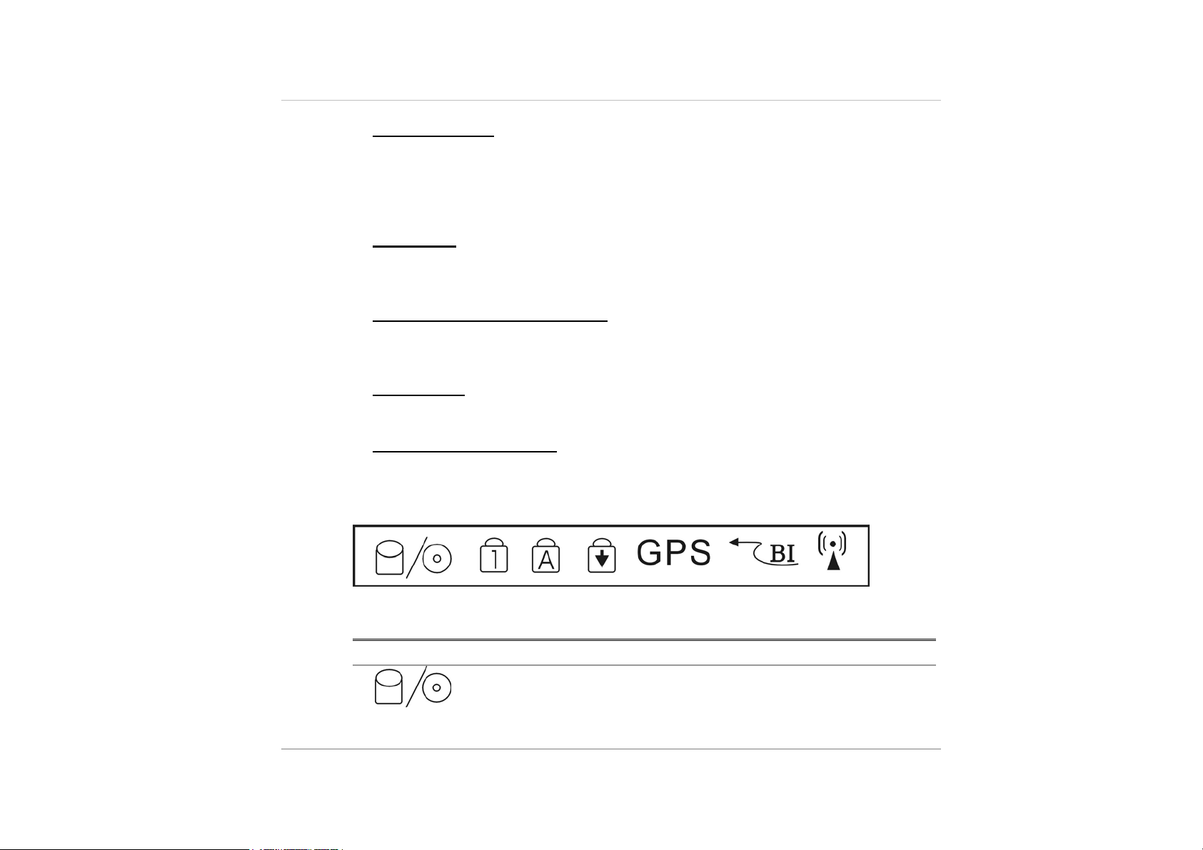
System Status Indicator
LED Graphic Symbol Indication
Green light indicates the hard drive and/or optical drive is
being accessed.
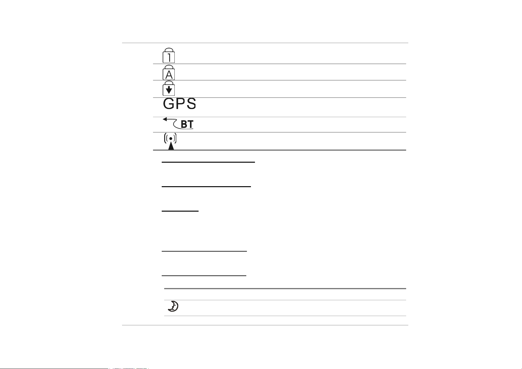
Green light indicates the numeric keypad is activated.
Green light indicates the cap-lock is activated.
Green light indicates the scroll-lock is activated.
Green light indicates the GPS (Global Positioning
Service) is activated.
Green light indicates the bluetooth is activated.
Green light indicates the wireless is activated.
13. BUILT-IN STEREO SPEAKERS
The built-in speakers output the sound in stereo.
14. THE BUILT-IN MICROPHONE
The built-in microphone is located directly at the left of the keyboard.
15. TOUCHPAD
The dual-button TouchPad is located below the keyboard. The TouchPad is
hardware-compatible with the IBM PS/2 mouse and software-compatible with the
Microsoft mouse.
16. SUSPEND LED INDICATOR
Indicates when the Notebook is in Suspend mode.
17. BATTERY LED INDICATOR
Indicates when the primary rechargeable battery is being dis-charged.
LED Graphic Symbol Indication
suspend mode.
5
Blinking green light indicates the notebook is in
18. TOUCHPAD BUTTONS
The buttons below the TouchPad correspond to the left and right buttons on a
standard mouse.
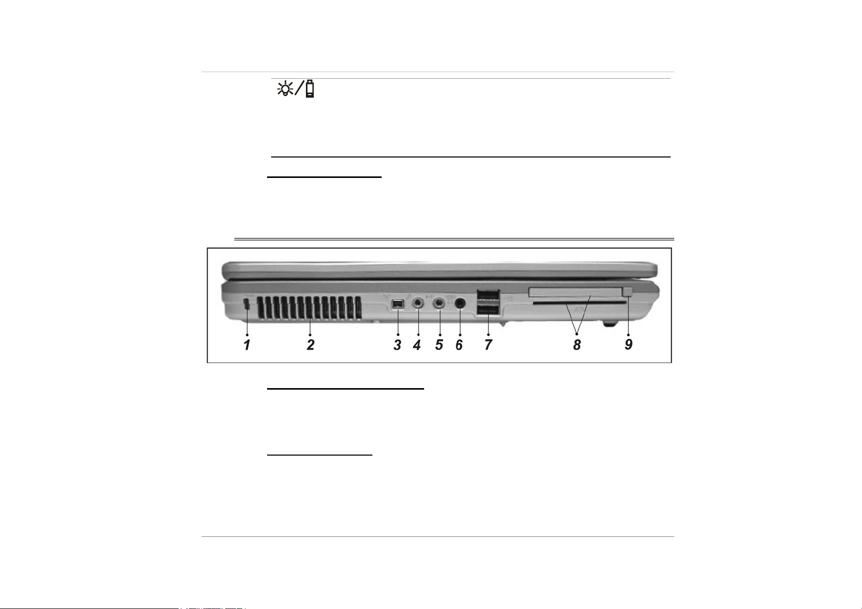
LEFT VIEW
Blinking orange light indicates the battery is being
charged when the system is turn ON.
Blinking red light indicates the battery is being
charged in when the system is turn OFF.
Blinking green light indicates the battery power is
currently low.
6
1.
KENSINGTON LOCK KEYHOLE
Your computer includes a keyhole to be used with a standard Kensington lock.
You can connect the Notebook lock to a large object with the Kensington lock to
prevent theft of your Notebook.
2. VENTILATION GRILL
The fan grill is where air is exchanged to dissipate the internal heat. Do not block
this airway completely.

3. 1394 USB
A fast external bus standard that supports data transfer rates of up to 400 Mbps
(400 million bits per second). Can be used to connect up 63 external devices,
also supports isochronous data -- delivering data at a guaranteed rate.
This makes it ideal for devices that need to transfer high levels of data in realtime, such as video devices. Also supports both Plug-and-Play and hot plugging,
and also provides power to peripheral devices.
4. MICROPHONE JACK
The microphone jack (3.5-mm diameter) is where you connect a microphone.
5. WIRELESS AND BLUETOOTH ON/OFF KEY
Press the On/Off key repeatedly to select one or both of wireless and Bluetooth
to enable or disable. When Wireless icon (key top) appears green, the wireless
LAN function is enabled.
6. STEREO HEADPHONE / SPDIF-OUT JACK
The stereo headphone jack (3.5-mm diameter) is where you connect the
headphones or external speakers. Alternatively, you may connect the SPDIF
output to an external DTS, AC3, or PCM sound processor / decoder in your home
stereo system.
7. USB 2.0 PORT (X2)
The Universal Serial Bus (USB2.0-compliant) port allows you to connect a wide
variety of devices to your computer at a rate of up to 480 Mbps. This port
conforms to the latest USB2.0 plug-and-play standards.
8. PC CARD SLOT (TYPE I & II PCMCIA)
The slot is where PC Card (Type II PCMCIA) is inserted. The system also
supports 1394, Smart card and 4-1 card reader.
7
9. CARD EJECT BUTTON
Press the eject button to release the PC Card.
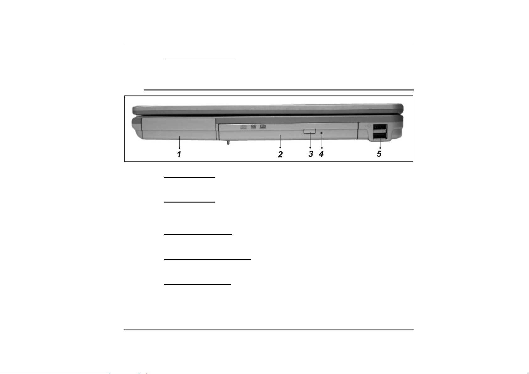
RIGHT VIEW
1.
BATTERY PACK
The battery pack is a built-in power source for the notebook.
2. OPTICAL DRIVE
If your computer comes with the CD-RW/DVD Combo/DVD Dual, you may save
data onto a CD-R / CD-RW or DVD RW disc.
8
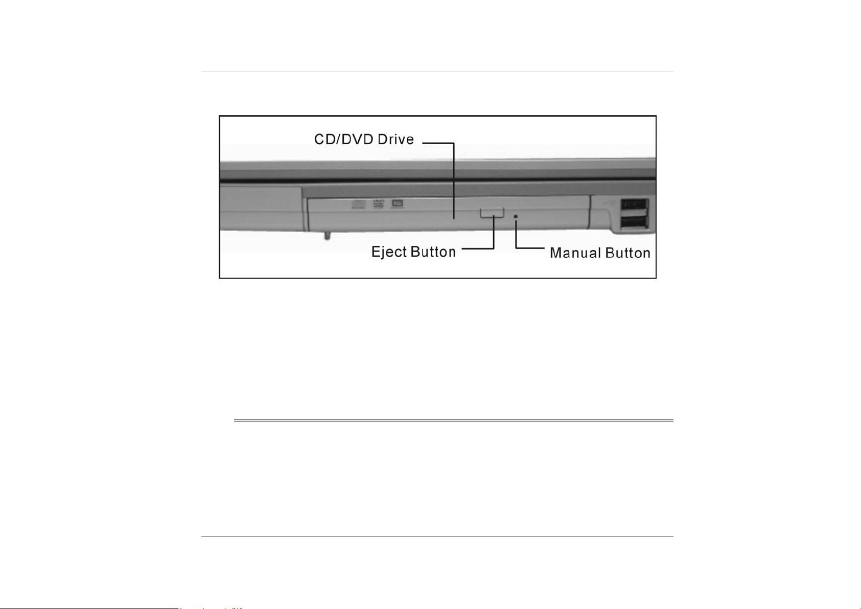
3. DISK EJECT BUTTON
Press the eject button to eject the disk tray.
4. MANUAL EJECT KEY HOLE
The manual eject keyhole allows you to manually eject a jammed disk.
5. USB 2.0 PORT (X2)
The Universal Serial Bus (USB2.0-compliant) port allows you to connect a wide
variety of devices to your computer at a rate of up to 480 Mbps. This port
conforms to the latest USB2.0 plug-and-play standards.
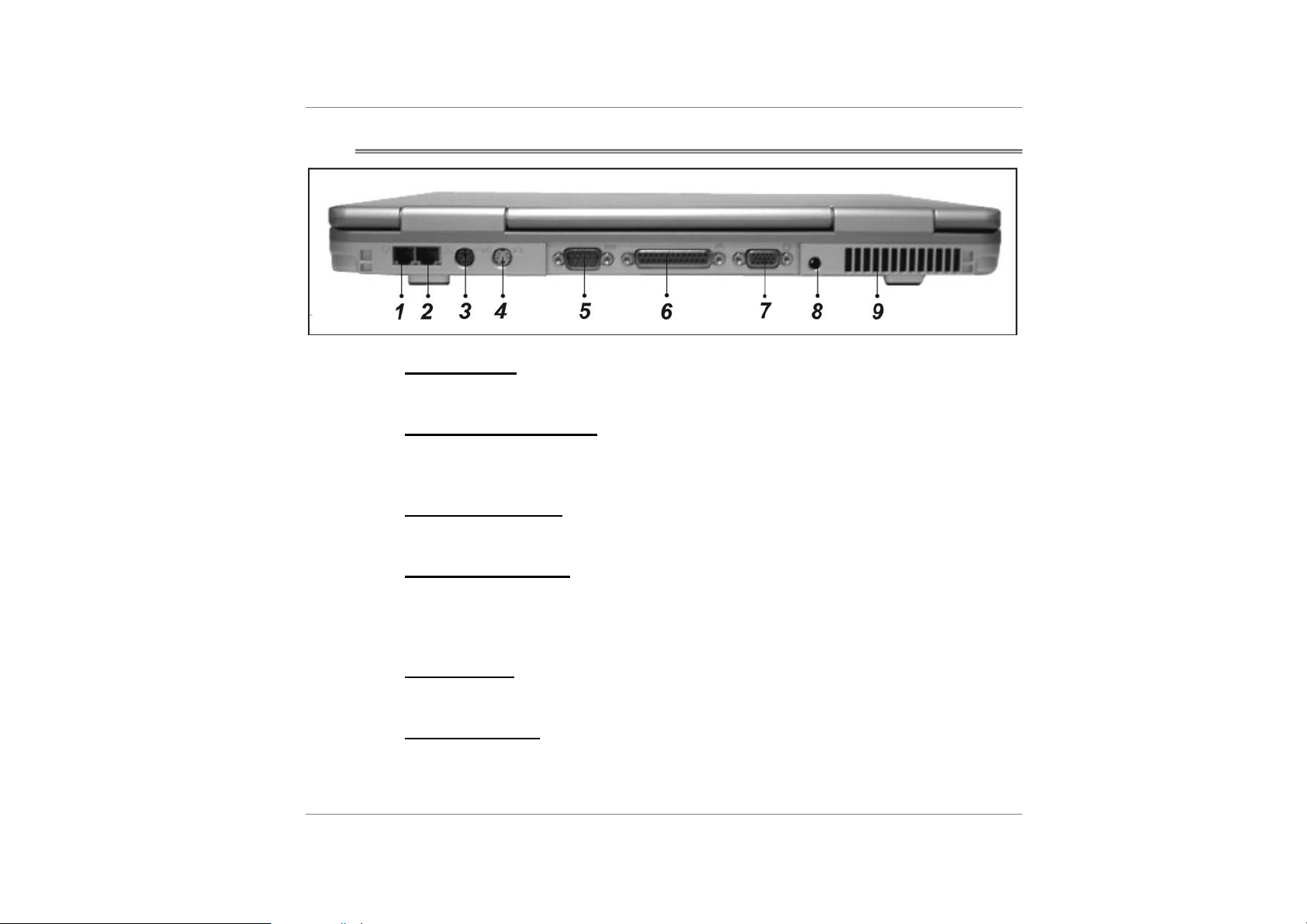
REAR VIEW
MODEM PORT
1.
This is where you plug the phone jack (RJ-11) for fax/modem functions.
2. ETHERNET / LAN PORT
The port connects to a network hub via the RJ-45 cable and also conforms to
10/100/1000Base-TX transmission protocol.
3. PS/2 SERIAL PORT
This is where you connect PS/2-type mouse or keyboard.
4. TV (S-VIDEO) PORT
The S-Video port permits you to redirect the screen output to a television set or
any analog video playback device. This TV Port is copyright protected; when
DVD movie is played, the output is scrambled to prevent analog recording.
5. SERIAL PORT
The 9-pin serial port connects to any serial-port devices.
6. PARALLEL PORT
The 25-pin parallel port connects to any parallel-port devices such as a printer.
9
7. EXTERNAL VGA PORT
The 15-pin VGA analog port is for connecting the external CRT monitor or
projector.
8. POWER JACK (DC-IN)
The DC-out jack of the AC Adapter connects here and powers the computer.
9. VENTILATION GRILL
The fan grill is where air is exchanged to dissipate the internal heat. Do not block
this airway completely.
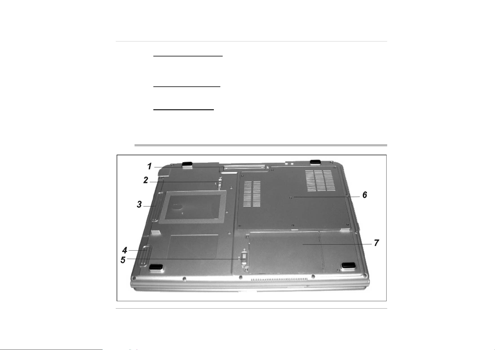
BOTTOM VIEW
10

1. PORT REPLICATOR PORT
The system can be docked onto an optional port replicator for additional input /
output ports.
2. SWAPPABLE DEVICE BAY LATCH
Push the latch and pull on the drive hard case to remove the swappable device.
3. SWAPPABLE DEVICE BAY
The optical drive resides in the Swappable Device Bay. Additionally, you may
also purchase an optional hard drive module, or an empty shell (to reduce travel
weight) to be used in this bay.
4. BATTERY PACK AND
The battery pack is a built-in power source for the notebook.
5. BATTERY LATCH
Slide the battery latch to release the battery pack.
6. EXPANSION COMPARTMENT
This compartment will serve as an expansion to upgrade your RAM module.
7. HARD DISK DRIVE BAY
This is where the hard disk drive is located. The hard disk drive stores all the
system data. The hard disk drive can be upgraded to a larger capacity.
11

S
S
S
Operating Environment
You can use your computer under a wide range of environmental conditions. However, to ensure
long use and continued high performance, consider the following factors when setting up your
computer:
Set the computer on a flat, stable surface. To prevent damage to the computer’s hard disk
drive, avoid using the computer where it will be exposed to strong vibration.
Place the computer away from electromagnetic or radio frequency interference.
Avoid using or storing the computer where it will be exposed to extreme temperatures. In
particular, do not leave the computer in direct sunlight, over a radiator, or near a heat
source for a long period of time. High temperature can damage the circuitry.
T
T
T
A
A
A
R
R
R
T
T
T
I
I
I
N
N
N
G
G
G
R
U
O
Y
Y
Y
O
O
U
U
R
R
N
N
N
O
O
O
T
T
T
E
E
E
B
B
B
O
O
O
O
O
O
K
K
K
Avoid exposing the computer to high or low humidity. Extreme humidity can contribute to
disk drive failure.
If you are using the computer with the AC adapter, do not allow anything to rest on the
power cord. Do not place the computer where people can step on or trip over the cord.
The openings on the computer are provided to protect the computer from overheating. To
ensure reliable operation, leave about 10 cm (4 inches) around the computer for
unobstructed air circulation. Avoid exposing the computer to dust or smoke.
1

Connecting to a Power Source
You can use the provided AC adapter to supply your computer with power from an AC wall
outlet.
1. Place the computer so that you have easy access to its rear panel.
2. Plug the AC adapter’s connector into the DC-IN connector on the rear panel of the
computer.
3. Connect the power cord to the AC adapter and then to a wall outlet.
2
Do not use inferior extension cords as this may result in damage to your Notebook. An
AC adapter is provided along with your Notebook. Do not use a different adapter to power
the computer, and do not use the AC adapter to power other electrical devices.
Try not to turn off or reset your Notebook while the hard disk is in use.
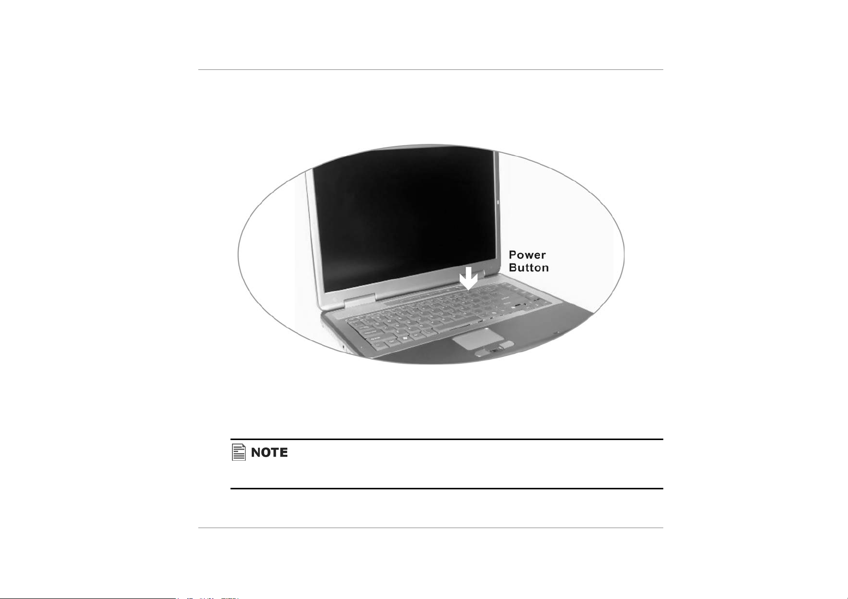
Turning on Your Notebook Computer
Before turning on your computer, make sure you are familiar with its features as mentioned in
previous chapter. Once you have set up your notebook you are now ready to turn it on. To do
this press the power button.
Operating on Battery Power
Your computer comes with a rechargeable battery pack that lets you operate the computer
without an external power source.
We recommend you to use batteries that are approved by an authorized dealer. Try not to
use the wrong battery for it would cause serious damage to your computer.
3
Battery Low-Power Warning
Low Battery Warning
Low battery condition occurs when battery power is reduced to 6%. The green power LED
indicator blinks and the system beeps once every 16 seconds or so.
Very Low Battery Warning
Very Low battery condition occurs at 3 % power remaining. The power LED indicator blinks
and the system beeps at 4-second interval. When the notebook warns you of its low battery
condition, you will have about 3-5 minutes to save your current work.
4
Do not expose battery packs to temperatures below 0 degree Celsius (32 degree F) or
above 60 degree C (140F). This may adversely affect the battery pack.
Inserting and Removing the Battery Pack
The battery pack should already be inserted in your Notebook computer when you unpack it. If it
is not inserted, follow these directions:
1. Turn off the notebook.
2. Turn the Notebook over and locate the battery compartment.
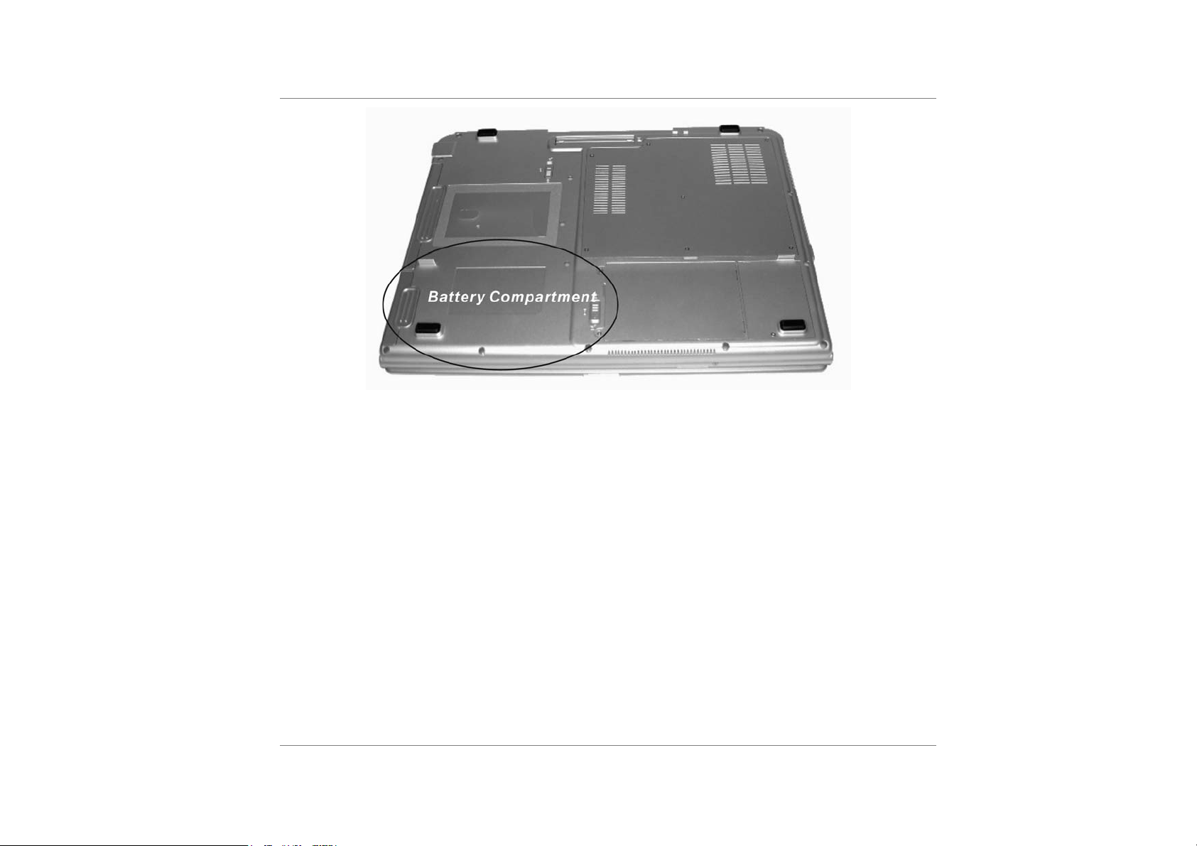
3. Insert the battery into the empty compartment. It is designed so that it only fits one
way. It should easily “click” into place.
4. Be sure that the battery release latch on the battery has clicked into place. This will
prevent the battery from sliding out of its compartment.
5
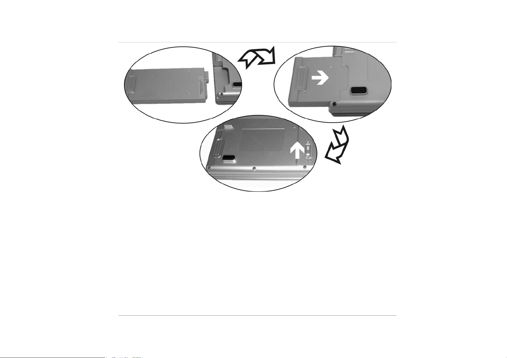
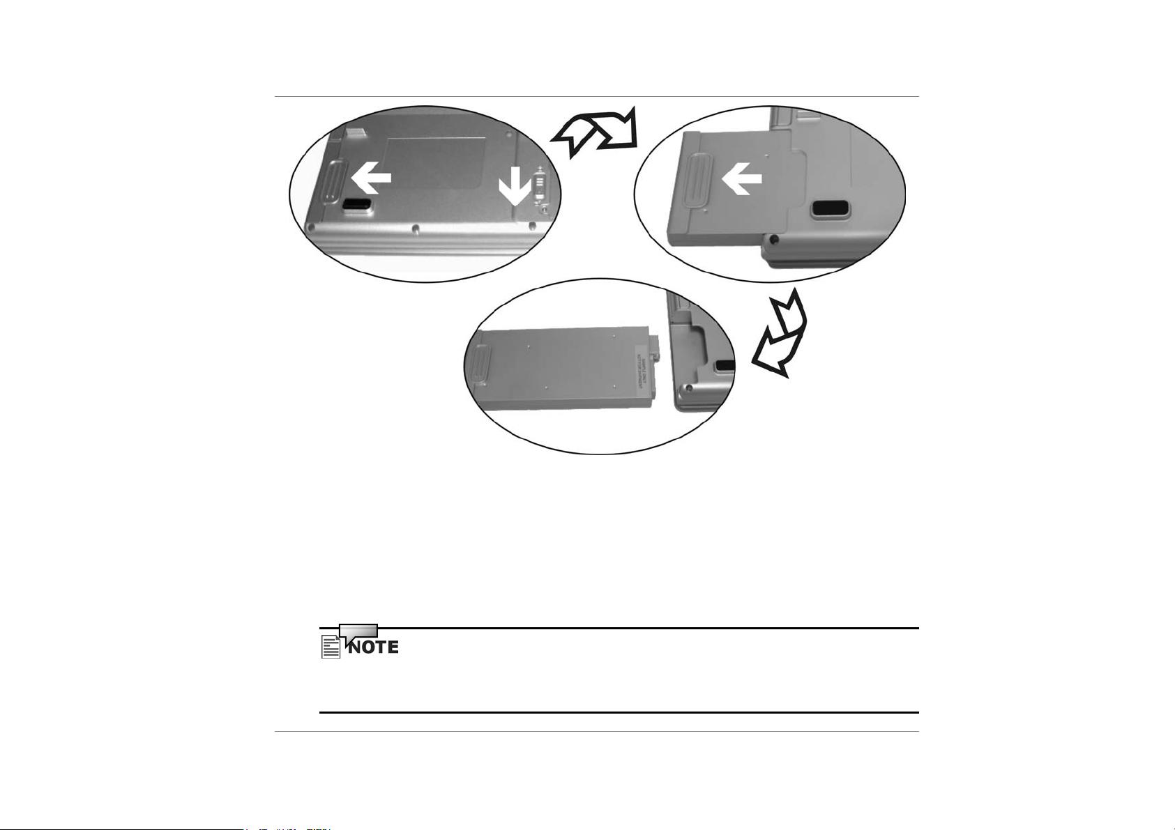
To remove the battery pack:
6
1. Turn off the Notebook.
2. Slide the battery latch into the direction of the arrow as shown in the illustration.
3. Hold the battery at the finger grip and slide the battery out.
Charging the Battery and Charging Time
To charge the battery, while the battery pack is in the notebook, plug the AC adapter into the
notebook and an electrical outlet.
The charging time is approximately 2.5 hours when the notebook is turned off and approximately
4.5-6 hours when the notebook is turned on.
When the battery is fully charged, the battery charge indicator becomes dark (off).
If system runs at heavy loading or in a high temperature environment, the battery may not
be fully charged. You need to continue to charge it with the AC adapter plugged in until
the charging LED turns off.
7

Checking the Battery Level
You can check the remaining battery power in the Windows battery status indicator, which is
located at the lower right-hand corner of the task bar. (If you do not see a battery or AC-in icon
on the task tray, go to Power Options Properties box and click on the Advanced tab. Check off
``Always show icon on the task bar``.)
Alternatively, you can access the power meter by clicking the Power Options icon in the
Windows Control Panel.
Prolonging the Battery’s Life and Usage Cycles
There are ways you can do to prolong the use of battery.
Use the AC adapter wherever AC wall outlet is available. This will ensure uninterrupted
computing.
Purchase additional battery pack.
Store the battery pack in room temperature. Higher temperature tends to deplete the
battery’s power faster.
Make good use of the power management function. Save To Disk (Hibernate) saves the
most energy by storing current system contents in a hard disk space reserved for this
function.
8
The life expectancy of the battery is approximately 300 recharges.
See the notices section in the beginning of the user manual on how to care for the battery
pack.
Read Section Protecting Your Notebook in the beginning of this manual for tips about
how to maintain the battery pack. To achieve optimal battery performance, you may need
to do a battery calibration at a 3-month interval. To do this:
Fully charge the battery.
Then discharge the battery by entering the BIOS setup screen. (Press F2 key as soon as you
turn on the computer. And let it remain at the setup screen until the battery runs out.
Fully charge the battery again.
Using Windows Power Options
Windows Power Management provides basic power saving features. In the Windows Power
Options Properties [Start > Settings > Control Panel > Power Options] dialogue box, you may
enter time-out values for display and hard disk drive. Windows power manager saves power by
turning off hard drive after 1 minute of inactivity, for example.
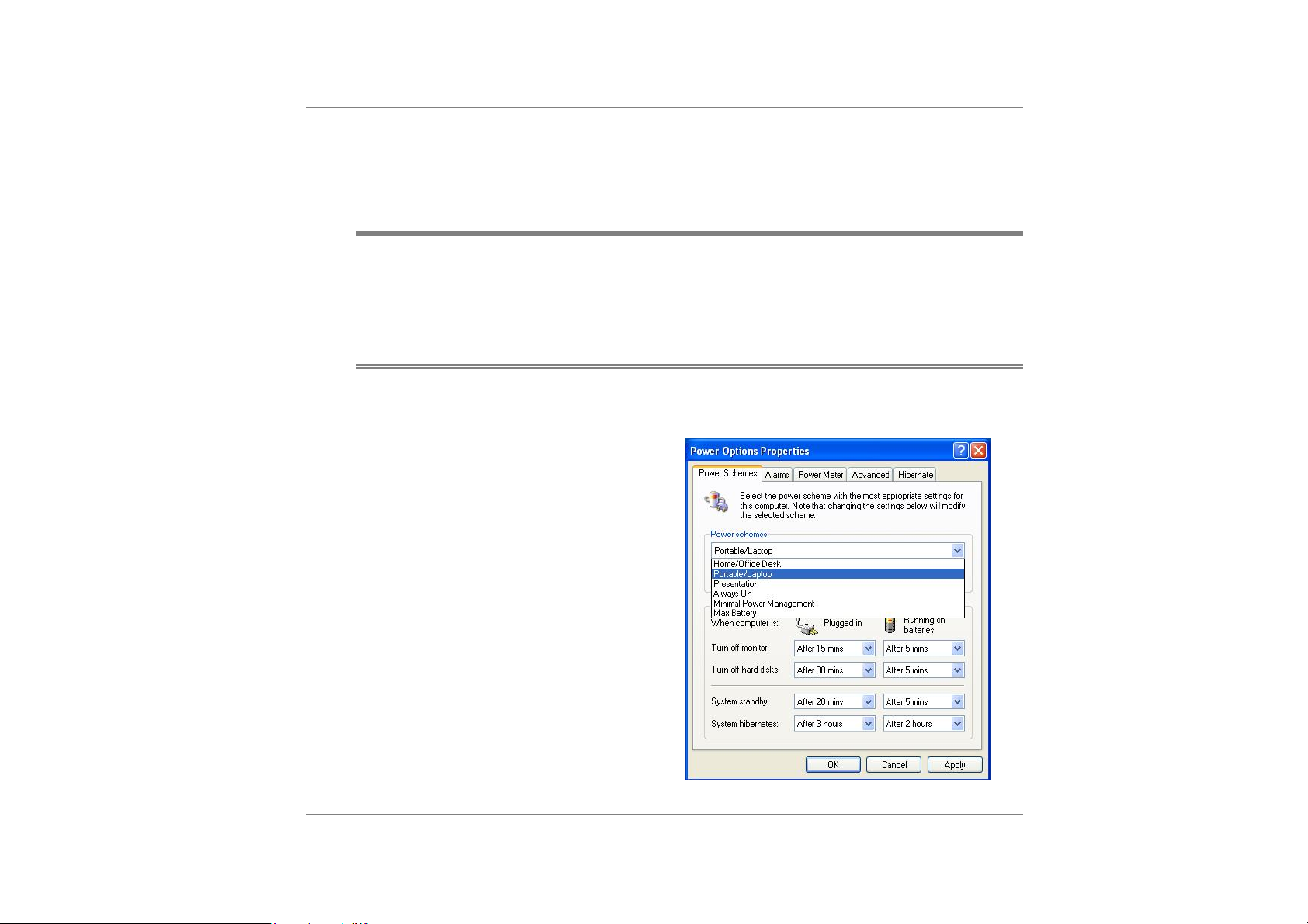
Windows’ Power Schemes
The power management control panel in Windows XP, known as Power Schemes, is designed to
provide the user with an easy-to-use interface. The Power Schemes tab can be found in the
Power Options Properties panel that is accessible via the control panel window.
Schemes are easy to understand, based on
notebook usage scenarios, and control not
only processor power usage but other
system peripherals as well.
Go to [Start > Settings > Control Panel]
and double-click the Power Options icon.
Always on mode puts the processor into
maximum performance mode, which
provides no power saving. The other
schemes control processor performance
based on demand. For example, Max
Battery mode lowers the processor’s speed
and voltage to conserve power as much as
possible.
9

In this dialog box, you can manually set the LCD and hard drive’s time-out values in the
Plugged in column and in the Running on batteries column. Lower time-out values will save
more battery power.
Also consult Windows user guide for more information on how to use Windows power
management functions. Actual dialogue box shown above may appear slightly different.
Suspend Mode
Standby Suspend
The system automatically enters this mode after a period of inactivity, which is set in the Power
Schemes dialog box. In Standby mode, hardware devices, such as display panel and hard disk,
are turned off to conserve energy.
Hibernate Suspend
In this mode, all system data are saved in the hard disk before powering down. When this mode
is activated, all system state and contents are saved to the hard disk drive after a period of
inactivity defined by the user. No power or very little power is drawn from the battery module
under this mode.
However, depending on how much RAM that have been installed on your computer, the amount
of time the system requires to restore all its previous contents can range from 5 to 20 seconds.
10
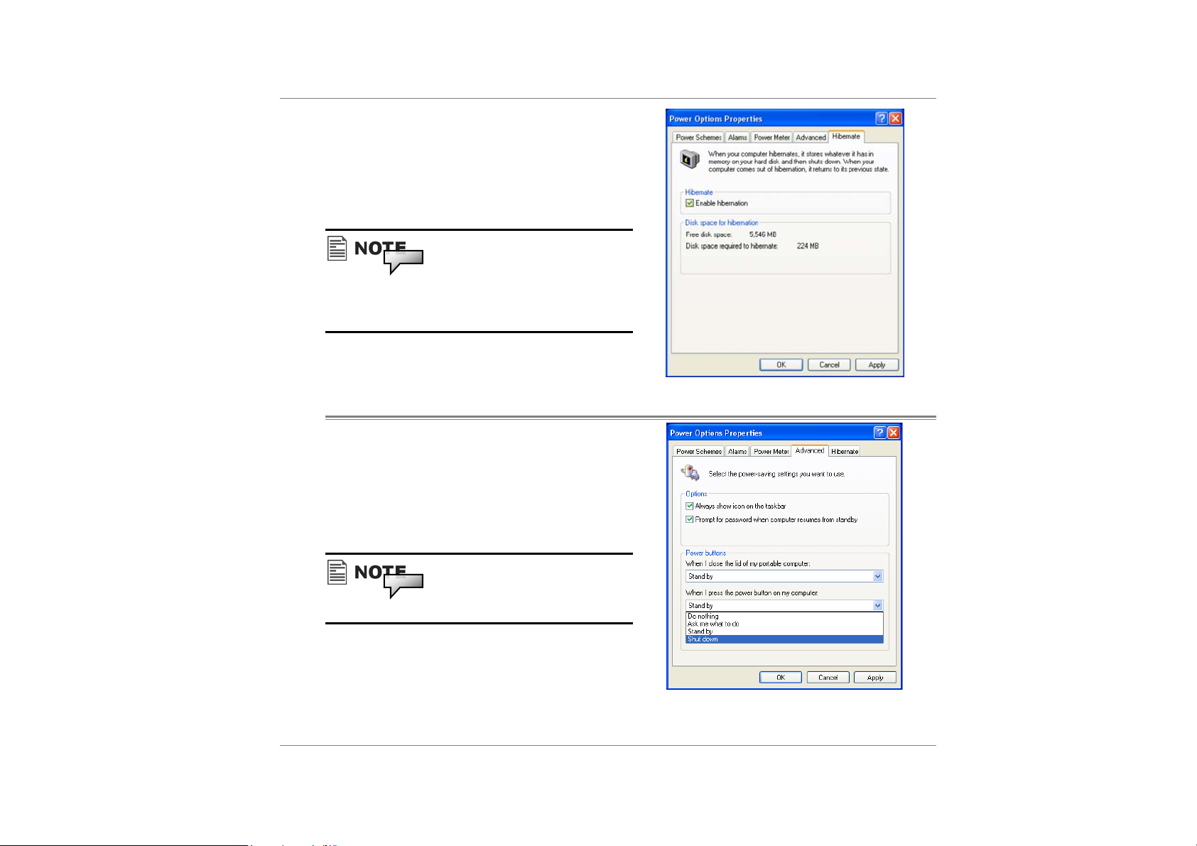
For Windows 2000 / XP users, hibernation is
handled by the operating system; therefore, no
special disk partition or disk file is necessary. If
you wish to activate Hibernate mode, you need
enable Hibernate Support in the Hibernate tab of
the Power Options menu.
Do not install or remove the memory module
when the system is in the suspend mode.
Actual dialogue box shown above may
appear slightly different.
Power Button Action
The notebook PC’s power button turns the
notebook on and off the system.
Go to [Start > Settings > Control Panel > Power
Options] and click on the Advanced tab. In the
pull-down menu, select how you wish the power
button to work as.
Actual dialogue box shown above may
appear slightly different.
11
In the When I close the lid of my portable computer pull-down menu, DO NOT select Do
nothing – otherwise the system will still run at high speed while the processor’s fan grill
is fully blocked by the closed LCD panel. The heat will damage the LCD panel.
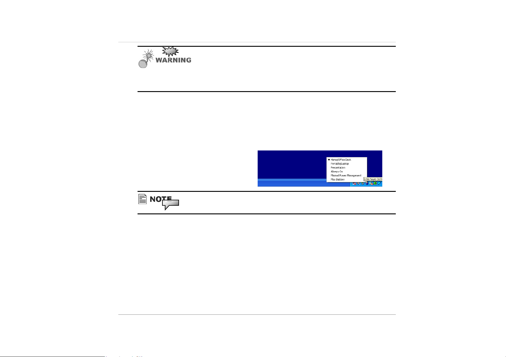
Power Menu Quick Access
Instead of making specific selections in the Power Options Properties box, you can quickly and
easily specify which pre-set power saving function you desire by clicking on the Battery icon at
the lower right-hand corner of the task bar. (If you do not see a battery or AC-in icon, go to
Power Options Properties box and click on the Advanced tab.
Check off ``Always show icon on the task
bar``.) Select Max Battery if you want the
system to enter suspend mode more often.
Or, select Always On if your notebook PC
is plugged into an AC power source.
Actual dialogue box shown above may appear slightly different.
12
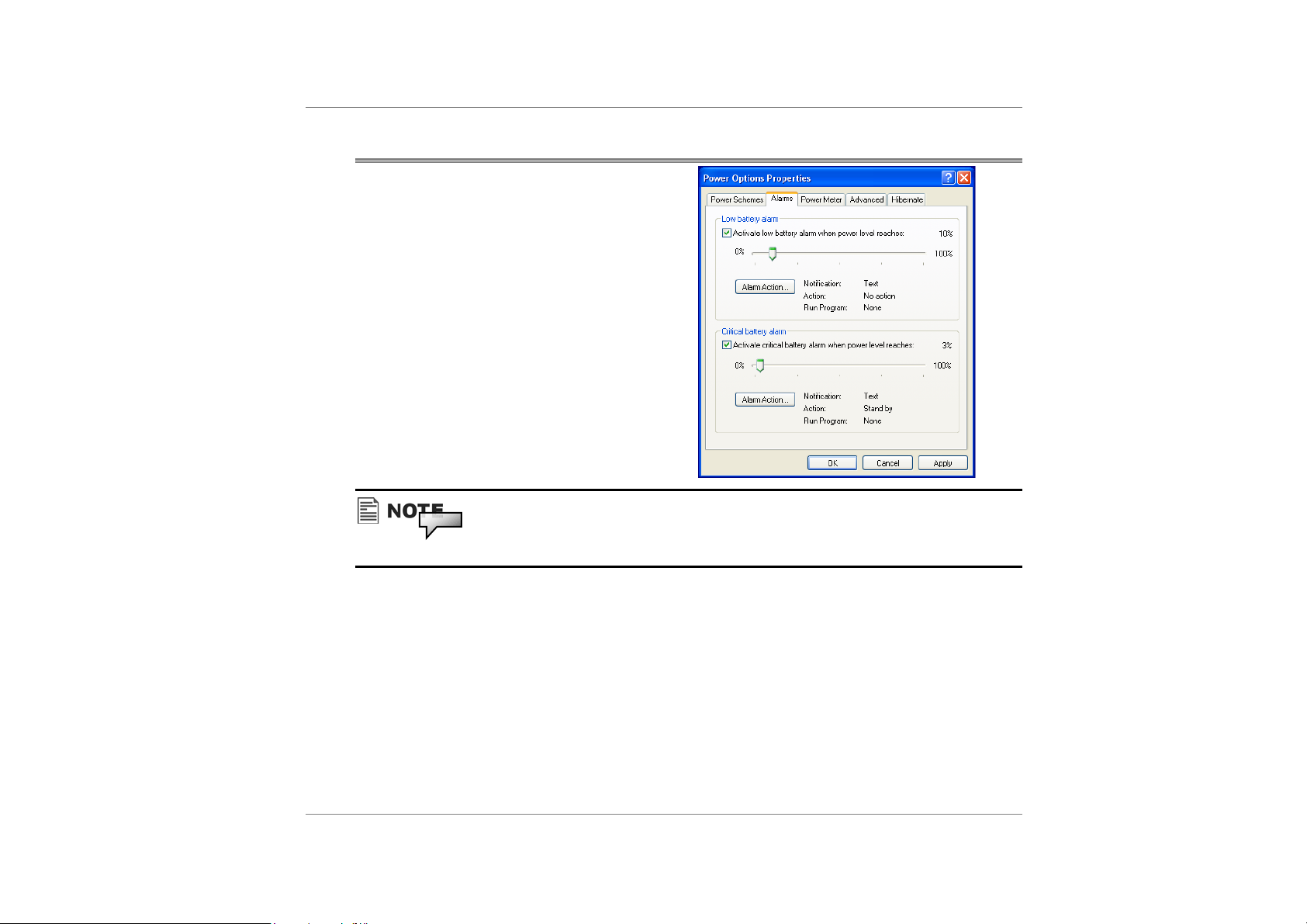
Low Battery Warning
You can define when and how the system
warns you of its battery-low condition.
Go to the Alarms tab in the Power Options
Properties box. If you wish to hear audible
beeps, click on the Alarm Action button
and put a check on Sound Alarm.
Consult Windows user guide for more information on how to use Windows power
management functions. Actual dialogue box shown above may appear slightly different.
13
CD/DVD Drives
The Notebook comes with a built-in CD-ROM drive module. The CD-ROM drive allows you to
run the latest multimedia CD titles providing a new educational and entertainment dimension to
your personal computing experience.
CD-ROM – these drives allow you to use data and audio CDs with your computer.
DVD-ROM – these drives have all the functions of a CD ROM/CD-RW in addition to
reading DVD disc. You can also record files and movies to recordable and re-recordable
DVD disc on compatible drives.
14
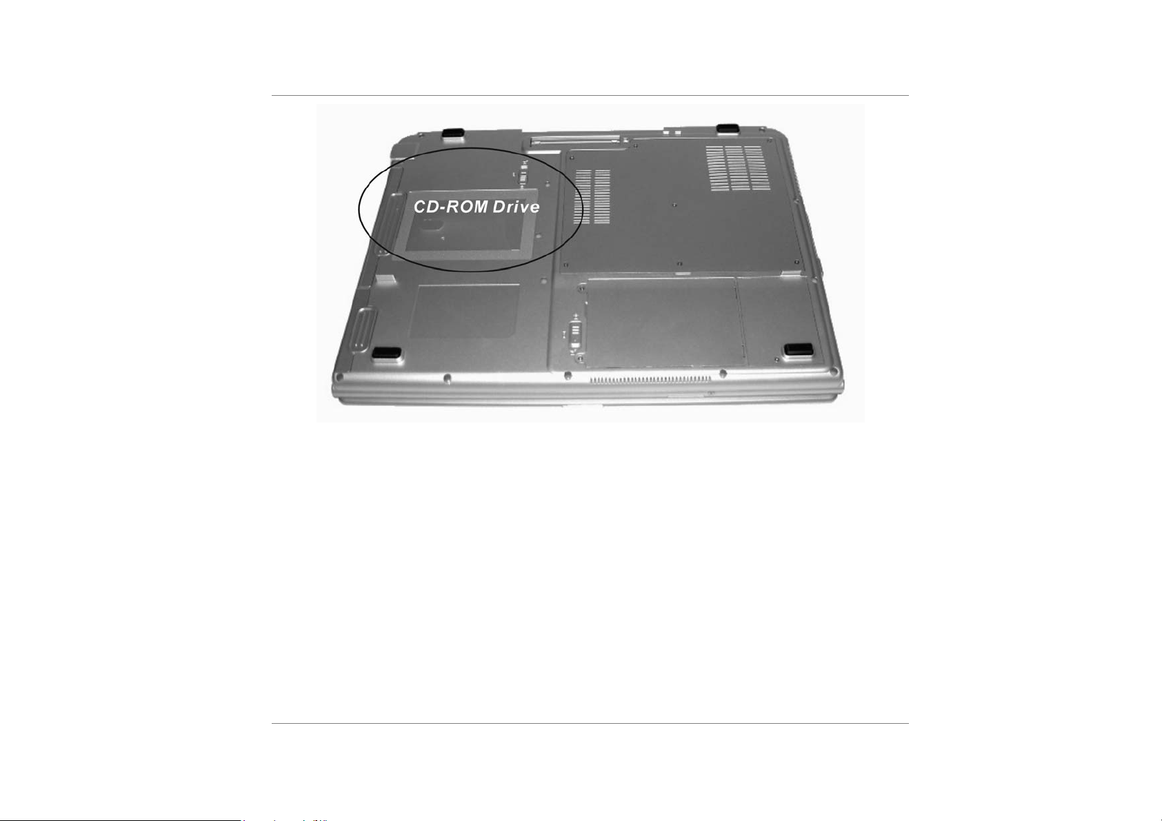
Removing the CD-ROM
The CD-ROM drive is removable and swappable with other modules to give you versatility
while minimizing weight and size. To remove the CD-ROM drive:
1. Save your work and turn off the computer.
2. Turn the Notebook over and locate for the CD-ROM drive.
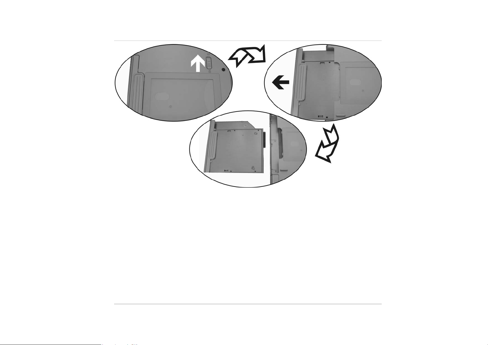
3. Push the CD-ROM release latch in the direction of the arrow indicated in the
illustration.
4. Pull on the CD-ROM finger grip as indicated in the illustration to slide the CD-ROM
module out of the bay.
5. To insert the CD-ROM module, slide the module into the drive bay so that it mates
with its connector. You will hear the release latch click shut.
15
The CD-ROM module can be swapped with a DVD module, second battery, secondary SATA
HDD or an Air bay (dummy).
16

Function Keys (Quick Keys)
Graphic Symbol Action System Control
Touch Pad On/Off
Fn + F1 Enters Suspend Mode.
Fn + F2 Touch Pad On/Off
Fn + F3 Changes Display Mode: LCD-only, CRT-only
and LDC&CRT.
17

Num Lk
Scr Lk
Touchpad
Fn + F4 Decreases Display Brightness.
Fn + F5 Increases Display Brightness.
Fn + F6 Mutes audio / sound
Fn + F7 Turns Speaker Volume down.
Fn + F8 Turns Speaker Volume up.
Fn + F9 Playback or Pause
Fn + F10 Stop
Fn + F11 Backward
Fn + F12 Forward
Number Lock Enables the embedded keypad to work in
numeric mode. The keys act like numeric
keypads in a calculator. Use this mode when
you need to do a lot of numeric data entry.
An alternative would be to connect an
external numeric keypad.
Fn + Scroll
Lock
Press the Scroll Lock key and then press ↑
or ↓to move one line up or down.
18
Your notebook touchpad is compatible
with the PS/2 mouse. A device driver is
not required for working with application
software that supports PS/2 mouse
operation.
The Touchpad is a pressure sensitive
pointing device that provides all the
features of a two-button mouse. Its primary
function is to move the cursor around the
screen.

Left button – click once to select an item, double-click to open a file or program.
Right button – use the right button to open special menus.
Memory card reader
Memory card readers are a relatively new
addition to notebook computers. They are
an ideal replacement for the floppy disk
drive because the cards are small and light
and have a large storage capacity.
The memory cards are used in a number of
consumer devices including:
Digital cameras
Mobile phones
Handheld games devices
PDAs
Graphic Subsystem
Your computer uses a high performance 15.4 inch WUXGA/WSXGA panel with high resolution
and multi-million colors for comfortable viewing.
Adjusting the Display Brightness
The notebook uses special key combinations, called hot keys, to control brightness.
Press Fn+F5 to increase the brightness.
Press Fn+F4 to decrease the brightness.
19

Audio Subsystem
Your computer’s audio subsystem is Sound Blaster Pro-compatible.
Adjusting the Volume Manually
To increase the volume, press Fn+F8.
To decrease the volume, press Fn+F7.
Adjusting the Audio Volume in Windows
Click the speaker symbol in the task tray in Windows.
Drag the volume control bar up or down to adjust the volume.
To temporarily silence the speaker without changing the volume setting, click Mute.
Voice Recording
A built-in microphone allows you to record sound. You will need to use audio processing
software to enable the built-in microphone. For example, you may use Microsoft Sound
Recorder.
Modem
20
Your computer comes with an integrated modem/Bluetooth module and a phone jack (RJ-11),
which is located on the left side of your computer. Use a telephone cable to connect the
computer to the telephone wall outlet.
Connecting the Modem
1. Plug one end of the phone line into the modem port located on the rear side of the
computer. (For EMI compliance, you need to clip the included EMI CORE to the
phone line.)
2. Plug the other end of the line into the analog phone wall outlet.
Depending on where your computer is used, you may need to change settings in the modem.
Correct setting will allow you to maintain a stable connection in a country where its
telecommunication system may be different to others.

To change the modem setting, do the following:
1. Go to [Start > Settings > Control Panel] and double-click on Modem Settings icon.
You will see a similar dialog box.
2. Click on the pull-down menu and select the country where it is applicable. Click on
OK to exit.
Ethernet
Your computer is equipped with a 10/100/1000Base-TX Fast Ethernet network adapter. Connect
the active LAN cable to the RJ-45 LAN port located on the left side of the computer. This allows
you to access and transmit data in the local area network.
Connecting to the Network
Use Unshielded Twisted Pair (UTP) Ethernet cable only.
1. Insert one end of the UTP cable into the network connector until the connector snaps
securely into the receptacle.
2. Either connect the other end of the cable to an RJ-45 jack wall outlet or to an RJ-45
port on a UTP concentrator or hub in the network.
Cabling Restriction for Networks
The following restrictions should be observed for 100/1000BASE-TX networks:
The maximum cable run length is 100 meters(m) (328 feet[ft]).
For 100/1000-Mbps operations, use Category 5 wiring and connections.
Consult Windows manual and / or Novell Netware user’s guide for the software
installation, configuration, operation of the network.
21

Using the Windows
H
ELP WINDOWS
For Windows XP help, click Start ÎHelp and Support icon will open the dialog box.
E
E
E
X
X
X
P
P
P
L
L
L
O
O
O
R
R
R
G
N
I
G
N
I
G
N
I
W
W
W
I
I
I
N
N
N
D
D
D
O
O
O
W
W
W
S
S
S
1

DESKTOP
Desktop may vary differently on the software installed in your notebook with different or
additional shortcuts.
2
Recycle Bin
Used for storing deleted files in case you want to recover and save it in your system. The files
will only be deleted from the Recycle Bin permanently only if you empty it by right clicking
your mouse and select the “Empty Recycle Bin”.

Start Button
Allows easy access to all Windows
programs.
The Start menu allows you to adapt
and show the programs used most
frequently. If you wish to keep an item,
right click the item and click Pin to
Start menu.
Log Off will enable the current user to
log off and allows a new user to log on.
Turn Off Computer allows you to shut
down, restart, and Stand by modes for
power saving purposes.
Taskbar
When you open a program, its icon is displayed at the taskbar for you to conveniently move
between programs by clicking the relevant button.
To add or remove toolbars from the taskbar: right click an empty spot on the taskbar, select
Toolbars Î choose the toolbar you want to add.
3

Notification
The icons that appear here are for quick
access to some programs and computer
functions that you frequently used. For
you to see the hidden icons, simply
click the
To prevent Windows XP from hiding
icons:
From an empty spot on the Taskbar,
right click your mouse and select the
Properties, remove the checked mark
on the Hide inactive icons.
icon.
CONTROL PANEL
4
It is in this area that you can change how Windows looks and works. Click Start Î Control
Panel dialog box. There are two interfaces – Classic View or Category View.

Desktop icons
Desktop icons give you easy access to your favorite programs and files. Double left-click an icon
to open it.
MY COMPUTER
Quick access your hard drives, CD/DVD drives, memory cards, your
documents and more.
5
MY NETWORK
You can access other computers, printers and shared files on your home
network from here.
RECYCLE BIN
When you delete a file it is sent to the Recycle Bin. You can also retrieve
the files that you deleted provided you haven’t emptied the Recycle Bin.
MY DOCUMENTS
This icon gives you quick access to your My Documents folder. This
contains all your personal files, music and photos.
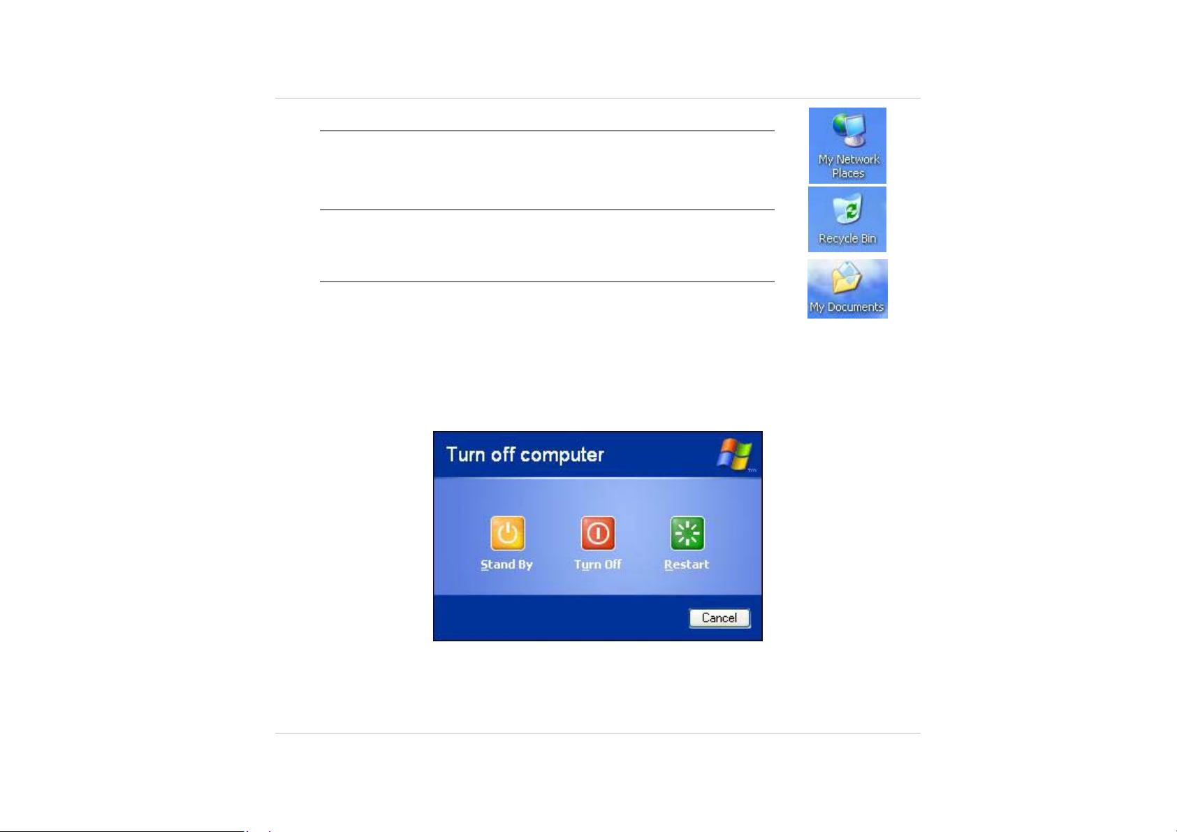
Turning off Your Notebook
When you finished working on your notebook it is recommended that you turn it off correctly.
This will help your computer to run smoothly. In order to turn off your computer correctly, click
Start then turn off. Several options will then appear on the screen:
Shut down – this option will close the Windows XP and turn off your computer.
6

Standby – this option will let your computer enter the power saving sleep mode. To return
to your work, move the mouse, press a key of your keyboard, or press the power button of
the computer.
Hibernate – if you choose this option Windows will take a snap shot of your current work
and save it to memory, then it will turn off. The next time you turn on your computer will
returned back to this saved condition.
Restart – this option will let you close Windows and restart your computer. This is
convenient in case a crash occurs for you to reset your computer or your computer is
running slowly.
7

P
U
T
B
I
O
I
I
O
O
S
S
S
B
B
The Setup Utility is a hardware configuration program built into your computer’s BIOS
(Basic Input/Output System). It runs and maintains a variety of hardware functions. It is a
menu-driven software, which allows you to easily configure and change the settings.
The BIOS contains manufacture’s default settings for the computer’s standard operations.
However, there are occasions when you may be required to modify the default settings in the
BIOS. For example, you may need to configure the BIOS power management (APM) settings if
you are using DOS, or non-Windows operating system.
The BIOS allows you to set up passwords to limit access to users. This is an important feature
because a great deal of vital information is carried within the computer nowadays. Unauthorized
access can be prevented. Later in this chapter, you will learn how to use this security feature.
S
S
S
E
E
E
T
T
U
U
P
P
Entering the BIOS Setup Screen
First turn on the power. When the BIOS perform the POST (Power-On Self Test), press F2 key
quickly to activate the AMI BIOS Setup Utility.
You may need to press F2 key fairly quickly. Once the system begins to load Windows,
you may have to retry by cycle-power on again
Leaving the BIOS Setup Screen
When you have finished modifying the BIOS settings, exit the BIOS. It takes a few seconds to
record changes in the CMOS.
1

BIOS Action Keys
Function Key Command Description
ESC Exit
Enter
F1 General Help Shows the Help Screen
F9 Default setting Load Optimal Defaults
F10 Save and Exit Saves changes and reboots the computer.
<Tab> Select a field Selects the next field.
↑
↓
- Lower value Selects the next value within a field.
+ Higher value Selects the next value within a field.
Go to Sub Screen
Select an item Selects the next upper item.
Select an item Selects the next lower item.
Leaves a sub-menu to return to the previous menu
OR exits the BIOS setup while saving changes.
Shows the Sub Menu
Modifying the BIOS Settings
The AMIBIOS setup main menu is subdivided into sub-menus. Each menu item is described in
this section.
2

MAIN SETUP
Under this menu, you may change time/date and view basic processor and system memory
information.
Date
Type in the current date, in MM/DD/YY format.
N/A
Time
Type in the current date, in HH:MM:SS format.
N/A
3

ADVANCED SETUP
CPU CONFIGURATION
Enabled you to configure the CPU settings
IDE CONFIGURATION
Primary IDE Master
Primary Master is where BIOS tries to boot from first. The primary master controls the hard
drive. Normally, Auto is selected.
4

Auto
Secondary IDE Master
The secondary master controls the ATAPI CD-ROM drive. Normally, Auto is selected.
Auto
S
UPER IO CONFIGURATION (PORT ADDRESS)
Parallel Port Address
You may choose a value for the parallel port.
Disabled/378/278/3BC
Parallel Port Mode
You may choose any one of these settings. ECP offers the best performance.
Normal/Bi-Directional/EPP/ECP
Parallel Port IRQ
You may choose any one of these settings. IRQ7 offers the best performance.
IRQ5/IRQ7
T
RUSTED COMPUTING
Configure settings related to Trusted Computing Innovations
COMMUNICATION
Wireless LAN
Enable or disable the internal wireless LAN module (optional.)
Disabled/Enabled
Bluetooth
Enable or disable the Bluetooth.
Disabled/Enabled
GPS
Enable or disable GPS function
Disabled/Enabled
5

SECURITY SETUP
BOOT SETTINGS CONFIGURATION
Change Supervisor Password
Install or Change the Password
N/A
Change User Password
Install or Change the Password
6

N/A
Using Password Protection
Two Levels of Password Protection are available. The BIOS provides both a Supervisor and a
User password. If you try to activate both passwords, the Supervisor password must be set first.
The passwords activate two different levels of protection:
1. System always asks for password every time it is powered on.
2. System asks for password only when you attempt to enter BIOS utility.
The passwords are encrypted and stored in NVRAM. Make sure you write them down or
memorize them. If you lost the passwords, the computer may need to be sent back to the factory
or to an authorized service dealer to reset the passwords.
BOOT SETUP
7

BOOT SETTINGS CONFIGURATION
Quiet boot
Disabled: Display normal POST message.
Enabled: Display OEM logo instead of POST messages.
Disabled/ Enabled
Bootup Num-Lock
Select Power-on state for Numlock.
Off/On
B
OOT DEVICE PRIORITY
1st Boot Device
Set the type of device for the 1st drive BIOS attempts to boot from.
2nd Boot Device
Set the type of device for the 2nd drive BIOS attempts to boot from.
3rd Boot Device
Set the type of device for the 3rd drive BIOS attempts to boot from.
Removable Dev/CD/DVD/Hard Drive/Disabled
8
H
ARD DISK DRIVES
st
1
Drive
Specifies the boot sequence from the available devices.
SATA: PM-FUJITSU MHV2040BH/Disabled
R
EMOVABLE DRIVES
st
1
Drive
Specifies the boot sequence from the available devices.
USB:USB Hotplug FDD/Disabled

CD/DVD DRIVES
st
1
Specifies the boot sequence from the available devices.
Drive
CD/DVD:SM-Slimtype COMBO SOSC-2/Disabled
EXIT SETUP
Saves Changes and Exit
After you have completed the BIOS settings, select this item to save all settings, exit BIOS Setup
utility, and reboot. New system settings will take effect on next power-up. F10 key can be used
for this operation.
9

Discard Changes and Exit
Exit system setup without saving any changes. Esc key can be used for this operation.
Discard Changes
Discards changes done so far to any of the setup questions. F7 key can be used for this operation.
Load Optimal Defaults
Load Optimal Default value for all the setup questions. F9 key can be used for this operation.
Load Failsafe Defaults
Load Failsafe Default value for all the setup questions. F8 key can be used for this operation.
10

R
U
O
Y
G
P
U
P
U
U
P
In this chapter, you will learn how to upgrade the DRAM, hard
disk drive, and to install the optional wireless LAN mini PCI
card.
G
G
R
R
A
A
D
D
I
I
N
N
G
G
Y
Y
O
O
U
U
R
R
C
C
C
O
O
O
A
R
G
M
M
M
P
P
P
U
U
U
N
I
D
T
T
T
E
E
E
R
R
R
Warning: We strongly recommend you sending your notebook back to your dealer or
agent for the specification upgrading.
When you upgrade your system, please turn off the power, disconnect the LAN and
Modem cable first for your safety.
After system upgrade, please screw all the screws before turn on.
1

Upgrading the Hard Disk Drive
Replacing the original drive with one of larger capacity can increase the hard drive capacity of
your computer. The computer uses a 9.5 mm (height), 2.5-inch Serial ATA type hard disk.
Be sure to make a backup copy of all your data before attempting this operation.
Hard drive upgrade is a delicate process. Please observe the following instructions
carefully or have a qualified technician install it for you. Damages due to mishandling of
this procedure are NOT covered by the manufacture’s warranty. Apply care when
handling the hard disk.
Do not drop or apply any shock.
Do not press on the cover.
Do not touch the connector with your fingertips.
Mishandling of the hard drive can result in permanent loss of data. Make a backup copy of
the drive s content before you remove it.
To replace the hard disk drive, do the following:
1. Turn OFF the computer. Unhook the AC cord and all cables/devices attached to the
notebook.
2. Place your hand on a large metal object momentarily to discharge any static electricity.
2

3. Un-screw the two screw that lock the HDD compartment.
4. Slide the HDD into the direction of the arrow as shown in the illustration.
5. Pull up the HDD away from the compartment.
3

Upgrading the System Memory
Many applications will generally run faster when the computer’s dynamic memory capacity is
increased. The computer provides two DDRII memory sockets, located underneath the keyboard.
You can increase the amount of memory by replacing the existing one with a dual inline memory
module (commonly known as DIMM) of a higher capacity.
4
Memory upgrade is a delicate process. Please observe the following instructions
carefully or have a qualified technician install it for you. Damages due to mishandling of
this procedure are NOT covered by the manufacture’s warranty.Changing memory while
your computer is in suspend or power-saving mode may cause permanent damage to the
hardware. Make sure you turn off the power and unplug the AC cord before proceeding
with a memory upgrade.

5

T
R
O
U
B
L
E
S
H
O
O
T
I
N
G
T
R
O
U
B
L
E
S
H
O
O
T
I
T
R
O
U
B
L
E
S
H
O
O
Your computer has been fully tested and complies with the system specifications before
shipping. However, incorrect operations and/or mishandling may cause problems.
This chapter provides a reference for identifying and correcting common hardware and software
problems that you may encounter.
When you encounter a problem, you should first try to go through the recommendations in this
chapter. Instead of returning the computer and waiting for repair, you may easily solve the
problems by considering the following scenarios and possible solutions. If the error continues,
contact your reseller for service information.
Before taking further actions, consider the following suggestions:
T
I
N
N
G
G
Check to see if the problem persists when all the external devices are removed.
Check to see that the green light indicator on the AC adapter is lit.
Check to see the power cord is properly plugged to the wall outlet and to the computer.
Check to see the power indicator of the computer is on.
Check to see if your keyboard is operational by pressing and holding any key.
Check for any incorrect or loose cable connections. Make sure the latches on the connectors
latch securely on to the receptor end.
1

Be sure you have not performed an incorrect setting on the hardware devices in the BIOS
Setup utility. A faulty setting may cause the system to misbehave. If you are not sure of the
changes you made, try to restore all the settings to factory defaults.
Be sure all the device drivers are installed properly. For example, without the audio driver
properly installed, the speakers and microphone will not work.
If external devices such as USB camera, scanner, printer do not function correctly when
connected to the system, it is usually the device’s own problem. Consult the device’s
manufacturer first.
Some software programs, which have not gone through rigorous coding and testing, may
cause problems during your routine use. Consult the software vendor for problem solving.
Legacy peripheral are not plug-and-play capable. You need to restart the system with these
devices powered up and connected first.
Be sure to go to BIOS SETUP and load DEFAULT SETTING after BIOS re-flash.
Be sure the Quick Key Lockout Switch on the bottom of the computer is not engaged;
otherwise the quick keys will not work.
Audio Problems
No speaker output -
2
Turn up the volume dial located at the right edge of the computer. See Chapter 1 for its
location.
Software volume control is turned down in Microsoft Sound System or is muted. Double-
click the speaker icon on the lower right corner of the taskbar to see if the speaker has been
muted or turned down all the way.
Most audio problems are software-related. If your computer worked before, chances are
software may have been set incorrectly.
Go to [Start > Settings > Control Panel] and double-click the Sounds and Audio Devices
icon. In the Audio page, make sure that Realtek ALC880 Audio is the default playback
device.

Sound cannot be recorded -
Double-click the speaker icon on the lower right corner of the taskbar to see if the
microphone has been muted.
Click Options and select Properties.
Select Recording and click the OK button.
After Click OK button, the recording volume control panel will appear.
Go to [Start > Settings > Control Panel] and double-click the Multimedia icon (or Sounds
and Audio Devices icon). In the Volume or Audio page, make sure that Realtek ALC 880
Audio is the default recording device.
Hard Disk Problems
The hard disk drive does not work or is not recognizable -
If you had just performed a hard disk upgrade, make sure the hard drive connector is not
loose and the hard disk drive is also correctly seated. Remove it and reinsert it firmly, and
restart your PC. (Refer to Chapter 4 for details.)
The new HDD may need to be partitioned and reformatted. O/S and drivers will need to be
re-installed as well.
Check the hard disk indicator LED. When you access a file, the LED lamp should light up
momentarily.
The new HDD may be defective or is not compatible.
If your computer has been subjected to static electricity or physical shock, you may have
damaged the disk drive.
The hard drive is making abnormal whining noises -
You should back up your files as soon as possible.
Make sure the source of noise is indeed from the hard drive and not the fan or other devices.
The hard disk drive has reached its capacity -
Run Disk Cleanup utility in Windows. [Start > All Programs > Accessories > System Tools
> Disk Cleanup] The system will prompt you for what to do.
Archive files or programs that you had no longer used by moving them to an alternative
storage medium (floppy disk, optical record-able disk, etc.) or uninstall programs that no
longer use.
3

Many browsers store files in the hard drive as a cache to speed up the performance. Check
the program’s Online Help for instructions on decreasing the cache size or on removing
temporary Internet files.
Empty the Recycle Bin to create more disk space. When you delete files, Windows saves
them to the Recycle Bin.
The hard disk takes longer to read a file -
If you have been using the drive for a period, the files may be fragmented. Go to [Start >
Programs > Accessories > System Tools > Disk Defragmenter] to perform a disk
defragmentation. This operation may take a while.
Interrupt requests or problems with other hardware devices may have occupied the CPU
and therefore slows down the system performance.
The files are corrupted -
Run the Error-checking utility in Windows to check the HDD. Double-click My Computer.
Right-click C: and select Properties. Click Check Now in Error-checking in Tools.
Optical Drive Problems
The optical drive does not work -
Try rebooting the system.
4
The disk is damaged or files are not readable.
After you have inserted a CD-ROM disk, it may take a moment before you can access its
content.
The drive dose not read any disks -
The CD may not be properly seated in the tray. Make sure the disk is firmly seated onto the
spindle.
The disk is damaged or not readable.
The disk cannot be ejected -
Normally, it takes a few seconds to eject the disk.

If the disk cannot be ejected, it may be mechanically jammed. Straighten out a paper clip
and insert it to a tiny hole next to the eject button. This should reject the disk tray. If not,
return the unit for repair. Do not forcefully pull on the disk tray.
The Combo or DVD RW drive (optional device) cannot record -
You need to purchase and install a burner utility program to record files to a blank media.
Display Problems
The display panel is blank when the system is turned on -
Make sure the computer is not in the Standby or Hibernate suspend modes. The display is
turned off to conserve energy in these modes.
The screen is difficult to read -
The display resolution should at least be set to at least1024x768 for optimal viewing.
Go to [Start > Settings > Control Panel] and double-click the Display icon.
Under the Settings page, set screen resolution to at least 1024x768 and choose at least 256
colors.
The screen flickers -
It is normal if the display flickers a few times during shutting down or powering up.
Keyboard, Mouse and Touchpad Problems
The built-in touch pad performs erratically -
Make sure there is no excess perspiration or humidity on your hand when using the touch
pad. Keep the surface of the touch pad clean and dry.
Do not rest your palm or wrist on the surface of the touch pad while typing or using the
touch pad.
Make sure Touch Pad On/Off function (Fn+F2) is not activated.
The built-in keyboard accepts no input -
If you are connecting an external keyboard to the system, the built-in keyboard may not
work.
Try restarting the system.
5

The characters on the screen repeat while I type.
You may be holding the keys down too long while you’re typing.
Keep the keyboard clean. Dust and dirt under the keys could cause them to stick.
Configure the keyboard to wait longer before the auto repeat feature starts. To adjust this
feature, Go to [Start > Settings > Control Panel], and double-click the Keyboard icon. A
dialogue box shows up with the adjustable settings for the keyboard.
CMOS Battery Problem
A message “CMOS Checksum Failure” displays during the booting
process or the time (clock) resets when booting -
Try to reboot the system.
If the message “CMOS Checksum Failure” appears during the booting procedure even after
rebooting, it may indicate failure of the CMOS battery. If so, you need to replace the battery.
This battery normally lasts two to five years. The battery is of type CR1225 (3V).
Memory Problems
The POST does not show an increased memory capacity when you have
already installed additional memory -
6
Certain brands of memory module may not be compatible with your system. You should
ask your vendor for a list of compatible DIMM.
The memory module may not be installed properly. Go back to Chapter 4 to review the
details of this operation.
The memory module may be defective.
The O/S issues an insufficient memory error message during operation -
This is often a software or Windows-related problem. A program is draining the memory
resources.
Close the application programs you’re not using and restart the system.

You need to install additional memory module. For instructions, go to Chapter 4 Upgrading
Your Computer.
Modem Problems
The built-in modem does not respond -
Make sure the modem driver is loaded properly.
Make sure the modem is not disabled under CMOS configuration.
Go to [Start > Settings > Control Panel > Phone and Modem Options] and go to Modems
tab. Make sure Azalia Modem is listed. Otherwise, click the Add button to add the modem
drive, which is located in the factory CD-ROM (or floppy diskette).
Go to [Start > Settings > Control Panel > System] and click Device Manager button in the
Hardware page to check for possible resource or driver conflict. See Windows on-line help
or manual for how to handle such problems.
Make sure the phone line, which the computer is connected to, is working.
Connection difficulties -
Be sure to disable Call Waiting on the phone line.
Be sure to have the correct country setting where your computer is used. [Start > Settings >
Control Panel > Modem Settings > Configuration] In the Country/Area pull-down menu,
select the appropriate country setting.
Excessive line noise might cause the connection to be dropped. To check this, put the
regular phone handset on the line and placing a phone call. If you do hear abnormal noise,
try to make the modem connection with a different line or contact your local telephony
company for service.
Make sure the cable connection is firm.
Try a different receiver number and see if the problem persists.
7

Network Adapter / Ethernet Problems
The Ethernet adapter does not work -
Go to [Start > Settings > Control Panel > System > Hardware > Device Manager]. Double-
click on Network Adapters and check if Intel Gigabit PCI Fast Ethernet Adapter appears as
one of the adapters. If it does not exist, Windows has not detected the Intel Gigabit Fast
Ethernet adapter or the device driver has not been installed properly. If there is a yellow
mark or red-cross on the network adapter, it may be a device or resource conflict. Replace
or update the device driver from the factory CD-ROM disk or consult Windows manual on
how to solve the resource conflict problem.
Make sure the physical connections on both ends of the cable are good.
The hub or concentrator may not be working properly. Check to see if other workstations
connected to the same hub or concentrator is working.
The Ethernet adapter does not appear to operate in the 100/1000Mbps
transmission mode -
Make sure the hub you are using supports 100/1000Mbps operation.
Make sure that your RJ-45 cable meets the 100/1000Base-TX requirements.
Make sure the Ethernet cable is connected to the hub socket that supports 100/1000Base-
TX mode. The hub may have both 100/1000Base-TX and 100/1000Base-T sockets.
PC Card / PCMCIA Problems
Some system may not have the PC Card Slot option.
PC Cards do not function-
Make sure you have properly installed the driver for the card.
Consult the card’s manual or contact the vendor for trouble-shooting.
8

The PC card cannot be recognized -
Windows NT4.0 does not support PCMCIA (PC Card) function. You may need an external
program for this.
Make sure the card is fully inserted; the outer end of the card should be even with the edge
of the computer.
Remove and insert the PC card again.
Make sure there is no IRQ conflict with the card. See Windows on-line help for solving
IRQ conflicts.
Reboot the computer and see if the problem persists.
The card may be defective. Try the card on another system, if possible.
Windows crashes or freezes when you remove the PC card-
Make sure you have <Stop> the PC card before removing it. Double-click the Safely
Remove Hardware icon at the lower right corner of the task bar and select the card you
wish to stop. When you click <Close>, in few seconds Windows will prompt you to remove
the card.
Performance Problems
The computer becomes hot -
In a 35
50 degrees.
o
C environment, the certain areas of the computer’s back case are expected to reach
Make sure the air vents are not blocked.
If the fan does not seem to be working at high temperature (50 degrees Celsius and up),
contact the service center.
Certain programs that are processor-intensive may increase the computer temperature to a
degree where the computer automatically slows down its CPU clock to protect itself from
thermal damage.
The program appears stopped or runs very slowly -
Press CTRL+ALT+DEL to see if an application is still responding.
Restart the computer.
9

This may be normal for Windows when it is processing other CPU-intensive programs in
the background or when the system is accessing slow-speed devices such the floppy disk
drive.
You may be running too many applications. Try to close some applications or increase
system memory for higher performance.
The processor may have been overheated due to the system’s inability to regulate its
internal heat. Make sure the computer’s ventilation grills are not blocked.
Printer Problems
The printer does not print -
Make sure the cable connection is secured and the printer is powered up, if the printer is
connected via the parallel port.
Run the printer self-test to see if it reports any problem.
Check if the printer displays any error messages. A paper jam may have occurred.
Make sure you have already installed the printer driver.
Try rebooting the system with the printer powered up and connected first.
The printer does not print what’s on the screen -
10
The information displayed on the screen may not exactly be the same as what is printed.
If the printer prints extra and strange symbols, it is the result of the cache (garbage) in the
printer memory buffer. Cancel all the printer tasks and toggle off the printer power switch
to clear up the memory buffer. Then, turn the printer back online and print again.
Make sure you install the correct printer driver.
The printer does not respond to infrared communication -
See Infrared Problems listed elsewhere in this chapter.

Firewire (IEEE1394) and USB2.0 Problems
The USB device does not work -
Windows NT 4.0 does not support USB protocols
Check the settings in the Windows Control Panel.
Make sure you have installed the necessary device drivers.
Contact the device vendor for additional support.
The IEEE1394 port does not work -
Go to [Start > Settings > Control Panel > System > Hardware > Device Manager]. You
should see an entry which reads “Texas Instrument OHCI Compliant IEEE 1394 Host
Controllers”. If it does not exist, Windows has not detected the host controller or the device
driver has not been installed properly. If there is a yellow mark or red-cross on the 1394
host controller, it may be a device or resource conflict. Replace or update the device driver
from the factory CD-ROM disk or consult Windows manual on how to solve the resource
conflict problem.
Make sure the cable is fully connected.
Make sure you have installed the necessary device drivers.
Contact the device vendor for additional support.
11

C
O
C
C
O
To expand your computing capabilities, you can add a variety of external devices to your
computer. You may, for example, want to add a mouse, modem, or a printer. The computer is
equipped with several interface ports, including an enhanced parallel (printer) port, a serial, and
USB ports. These are provided as a means of connecting peripheral devices to the computer.
External Keyboard/Mouse
You can use your computer with an optional external keyboard, or IBM PS/2 compatible mouse.
The devices are “hot pluggable”. You do not have to power down the Notebook to connect these
devices.
You can either connect
A traditional external keyboard or
An IBM PS/2 compatible mouse or
A USB keyboard/mouse or
A wireless keyboard into
N
N
N
N
E
E
C
C
T
T
I
I
N
I
T
C
E
N
N
O
N
N
G
G
G
P
P
P
E
E
E
R
R
R
I
P
I
P
I
H
H
E
E
R
R
A
A
L
L
D
D
D
E
E
E
V
V
V
I
I
E
H
P
I
C
C
C
E
E
E
S
S
S
L
A
R
You can opeate both the internal keyboard and an external keyboard at the same time.
The PS/2 compatible mouse will work with the Notebook PC’s TouchPad simultaneously.
1

2

External Monitor
You can use optional display monitor with your computer.
Plug the monitor’s signal connector into the external VGA monitor on the rear panel of the
computer.
Secure the monitor cable to the external monitor port using the screws on the monitor cable.
Plug the monitor’s power cable into a wall outlet.
Turn on the monitor and adjust the monitor stand so that you have a good viewing angle of
the screen.
Parallel Printer
Your Notebook computer is equipped with an enhanced bi-directional parallel port.
The parallel port is the most widely used interface on personal computers because it usually does
not require setup commands or special configurations on either the computer or the peripheral
device.
3

TV Out
You can connect a TV monitor to the Notebook’s S-Video port and view the Notebook’s video
output.
4

E
H
T
G
N
I
S
U
S
U
U
S
The GPS, short for Global Positioning System, transmit digital radio signals that contain data on
the satellites location and exact time to the earth-bound receivers. GPS has applications beyond
navigation and location determination. GPS can also be used to monitor the movement of people
and things and bringing precise timing to the world.
SYSTEM REQUIREMENT
PC notebook with x86 CPU
Windows 2000/XP
GSM/GPS module installed
INSTALLATION
G
N
I
G
N
I
H
T
T
H
E
E
G
G
G
P
P
P
S
S
S
1. Launch setup.exe
2. Change the destination directory if needed, then click the square button to proceed with
the installation.
OPERATION
1. Launch Secure.exe, wait till the initialization finished.
1

2. Click the [Settings] button to set parameters.
2
•
COM Port is the serial port where the SIM/GPS module is connected.
• Password is the one that user should enter every Check Interval, or the notebook is
moved beyond the Distance since its last check.
• Notify Phone# is the phone no. that the alert SMS is sent to if user fail to pass the
check.
• PIN is the PIN code, if any, of the SIM card.
• Check Security On to enable the security check, or uncheck it to disable the security
check.
• Click the OK button to save changes, or the Cancel button to discard changes.

3. Leave the application running. When the password dialog shows up, enter the correct
password, or it will start to send alert SMS out every 60 seconds.

The following illustration gives you detail on how GPS will operate and transmit informations.
4

S
E
P
S
E
S
P
CPU
Intel
• Support for Intel Yonah Dual Core processor Pentium M , 667MHz FSB, 2MB L2
Cache,
• Support for Intel Yonah Single Core processor
• TDP 31W
• CPU Speed: Follow Intel the highest CPU speed.
• Keeping pace with Intel Roadmap through 2007 u-FCPGA Socket if possible
• Support Merom Dual Core CPU if the socket the same with Yonah.
M
EMORY
DDR DRAM
• 2 SODIMM sockets, up to 2048MB total system memory (highest memory
configuration with
• DDR II) 533/ 667MHz DDRII
• Accessible beneath keyboard per Intel design suggestion
• Allowance for changes in technology through 1
st
half of 2007.
C
C
F
I
I
F
A
C
I
A
C
I
A
C
I
F
I
C
E
P
T
T
T
I
I
O
I
O
O
N
N
N
S
S
S
C
ORE LOGIC
Intel 945PM
• Support Intel Pentium Dual(Single) Core processor FSB 667MHz
• Support DDR2 RAM, up to 2048MB total
• Discrete Graphics using (x16) PCI-Express
• Configurable as x2 or x4 DMI lanes
Intel ICH7M
• Support PCI-Express interface
• Support S-ATA controllers

• Support Ultra ATA 33/66/100
• Support 8 USB 2.0/1.1 devices
• Support Azalia (HD) controller
BIOS
(AMI)
• AMI 8Mbit BIOS memory
• Ability to turn off internal modem, LAN option, Wireless Lan (802.11x Golan),
Bluetooth
• GPS & Touch Pad
• UPEK (ST Micro) TBX for finger print security
• Landesk functionality
• Other BIOS options TBD.
G
RAPHICS
MXM TypeII supporting ATI & Nvdia
• Daughter card solution. PCI Express using MXM technology per Nvida specification
• ATI M56 Type II 128MB VRAM (high end, mid range, low end and workstation class
MXM
• cards)
• Nvdia NV73M 256MB standard MXM TypeII card (Outsourcing)
PCMCIA
(OZ711MP1)
• 1-32Bit Card bus (support for 1 typeI & II)
• (But still reserve circuit ,space and 1 internal usb port for future New Card)
• OZ711MP1 controller also support 1394, Smart card and 4-1 card reader
UDIO
A
(Realtek ALC861)
• Built-in Azalia Audio , 3D sound effects, 7.1 digital sound
• Built-in two 1.5W stereo speakers id space is available.
INI CARD
M
• 1 * Mini Card socket. Accessible from bottom case.

• Intel Golan WLAN 3945 A/B/G
LED
• Power on/ Charging status, Suspend status (on Main board)
• Caps Lock, Num Lock, Scroll Lock, HDD/CD, Wireless, Blue tooth , GPS (on LED
board)
P
OINT DEVICE
(Synaptic)
• Touch pad with latest S/W feature set. OTR is simultaneous with external PS/2 device
(including MS-Intellimouse). With imbedded UPEX touch strip. Touch strip should
allow horizontal and vertical scrolling. Look into styling this so it gives the
appearance of one piece on the palm rest
B
AYS
SATA HDD Bay
• Bottom loading tool less design (can’t compatible with 3100 series)
Multibay (Warm swappable through OS)
nd
• 2
• CD-RW/ DVD Combo/ DVD Dual
• Secondary SATA HDD
• Air Bay (Dummy)
Battery (6 cells, 1800mA, 3S2P )
P
OWER CONSUMPTION
• 110 Watts (with 1A charging)
• (120W Adapter slim tiny as possible)
P
OWER MANAGEMENT
• Fu Full feature ACPI power management, Stand-by, Suspend, Hibernation
• ACPI 3.0 supported with Intel SpeedStep
• With bridge battery
C
OMMUNICATIONS
Modem
• Castlenet MA820
LAN
• Intel Tekoa 82573E GigaLAN (support AMT)
WLAN
• Intel Golan WLAN 3945 A/B/G (Mini Card)

Blue tooth
• GUBTCR42M Billionton
GPS
• GPS module (could be enable/disable in BIOS and also has LED indicator)---fixed on
the bottom case door.
S
ECURITY
Finger strip
• STMicro touch strip UPEK
Password
• System password
TPM
• St Micro ST19WP18-TPM-C
• Kensington Lock
Smart Card
• Internal to the system. Running off PCMCIA controller, Smart card should
• be orientated so the smart chip must be inserted up. In this model we would like the
card slot
• so it can be orientated with the chip up.
K
EYBOARD
• 87/88-keys Keyboard
• 19mm pitch 2.5 mm travel length, 19mm pitch IBM style layout , support US
LCD
• 15.4” WUXGA
• 15.4” WSXGA+
M
AIN BATTERY
• 2400mA (8cells,4S2P)
I/O P
ORT
• 4 USB2.0
• 1 IEEE 1394
• 1 RJ-11

• 1 RJ-45
• 1 Microphone
• 1 Line In
• 1 Audio Out (SPDIF)
• 1 PCMCIA
• 1 VGA
• 1 S-Video
• 1 PS/2 (Y splitter of mouse and keyboard)
• 1 Port-replicator
• 1 Printer Port
• 1 Serial Port
• 1 Smart Card
• 1 DC-In
• 4 in 1 Card Reader (Built-in SD,MMC,MS 及 MS-Pro)
F
UNCTION KEYS
User definable Keys
• Fn+F1 Suspend switch
• Fn+F2 Turn On/ Off Touch Pad
• Fn+F3 LCD/ CRT/ LCD+CRT Switch
• Fn+F4 Brightness down
• Fn+F5 Brightness up
• Fn+F6 Mute
• Fn+F7 Volume Down
• Fn+F8 Volume Up
• Fn+F9 Media Play/Pause
• Fn+F10 Media Stop
• Fn+F11 Media Play Backward
• Fn+F12 Media Play Forward
• Fn+Num Lk , Scr Lk
HYSICAL OUTLINE DIMENSION
P
• 358mm x 262mm x 35mm
W
EIGHT
• 6.9 lbs with 8 cells battery (15.4 wide screen)

OPERATING SYSTEM
Microsoft
• Windows 2000, Windows XP SP2(with subsequence service releases), upcoming
64bit
Windows Vista.
PORT REPLICATOR
• Compatibility with 3000 series port replicator (PR1000)
ERTIFICATIONS
C
• WHQL apply only for Windows XP all drivers software and peripherals must be
WHQL certified with MID numbers.
• RoHs, WEEE (Uniwill)
• Macrovison, Energy Star, BQB (MPC)
R
EGULATIONS
• FCC, FCC Wireless, UL

A
G
E
N
C
Y
R
E
G
U
L
A
T
O
A
G
E
N
C
Y
R
E
G
U
L
A
A
G
E
N
C
Y
R
E
G
U
L
Federal Communications Commission Notice
This equipment has been tested and found to comply with the limits for a Class B digital device,
pursuant to Part 15 of the FCC Rules. These limits are designed to provide reasonable protection
against harmful interference in a residential installation. This equipment generates, uses, and can
radiate radio frequency energy and, if not installed and used in accordance with the instructions,
may cause harmful interference to radio communications. However, there is no guarantee that
interference will not occur in a particular installation. If this equipment does cause harmful
interference to radio or television reception, which can be determined by turning the equipment
off and on, the user is encouraged to try to correct the interference by one or more of the
following measures:
Reorient or relocate the receiving antenna.
Increase the separation between the equipment and the receiver.
Connect the equipment into an outlet on a circuit different from that to which the receiver is
connected.
Consult the dealer or an experienced radio or television technician for help.
A
T
T
O
O
R
R
R
Y
Y
Y
N
N
N
O
O
O
T
T
T
I
I
I
C
C
C
E
E
E
S
S
S
This device complies with Part 15 of the FCC Rules. Operation is subject to the following two
conditions: (1) This device may not cause harmful interference, and (2) this device must accept
any interference received, including interference that may cause undesired operation.
FCC Caution: Any changes or modifications not expressly approved by the party responsible for
compliance could void the user's authority to operate this equipment.
1

IMPORTANT NOTE:
FCC R
FCC RF Radiation Exposure Statement:
This Transmitter has been demonstrated co-location compliance requirements with (Intel
wireless 802.11abg module, FCC ID:WM3945ABG ).This transmitter must not be co-located or
operating in conjunction with any other antenna or transmitter.
This equipment complies with FCC RF radiation exposure limits set forth for an uncontrolled
environment. This equipment should be installed and operated with a minimum distance of 20
centimeters between the radiator and your body.
According to FCC 15.407(e), the device is intended to operate in the frequency band of 5.15GHz
to 5.25GHz under all conditions of normal operation. Normal operation of this device is
restricted to indoor used only to reduce any potential for harmful interference to co-channel MSS
operations.
ADIATION EXPOSURE STATEMENT:
MODIFICATIONS
The FCC requires the user to be notified that any changes or modifications made to this device
that are not expressly approved by the Manufacture may void the user’s authority to operate the
equipment.
CONNECTIONS TO PERIPHERAL DEVICES
2
Connections to this device must be made with shielded cables with metallic RFI/EMI connector
hoods to maintain compliance with FCC Rules and Regulations.
DECLARATION OF CONFORMITY
This device complies with Part 15/68 the FCC Rules. Operation is subject to the following two
conditions: (1) this device may not cause harmful interference, and (2) this device must accept
any interference received, including interference that may cause undesired operation.
EUROPEAN NOTICE

Products with the CE Marking comply with both the EMC Directive (89/336/EEC) and the Low
Voltage Directive (73/23/EEC) and R&TTE Directive (1999/5/EC) issued by the Commission of
the European Community.
Compliance with these directives implies conformity to the following European Norms:
EN55022 (CISPR 22) Radio Frequency Interference
EN50082 (IEC801-2, IEC801-3, IEC801-4) Electro-magnetic Immunity
EN 300 328-2, EN 300 328-1, EN 301 489-1, EN 301 489-17 (ETSI 300 328, ETSI 301
489) Electro-magnetic Compatibility and Radio Spectrum Matter.
TBR21 (ETSI TBR21) Terminal Equipment.
EN60950 (IEC950) I.T.E. Product Safety

CANADIAN NOTICE
This digital apparatus does not exceed the Class B limits for radio noise emissions from digital
apparatus as set out in the radio interference regulations of the Canadian Department of
Communications.
Le present appareil numerique nemet pas de bruits radioelectriques depassant les limites
applicables aux appareils numeriques de Classe B prescrites dans le reglement sur le brouillage
radioelectrique edicte par le Ministere des Communications du Canada.
POWER CORD REQUIREMENT
The power cord supplied with the AC adapter should match the plug and voltage requirements
for your local area. Regulatory approval for the AC adapter has been obtained using the power
cord for the local area. However, if you travel to a different area and need to connect to a
different outlet or voltage, you should use one of the power cords listed below. To purchase a
power cord (including one for a country not listed below) or a replacement ac adapter, contact
your local dealer.
U.S. AND CANADA
The cord set must be UL-Listed and CSA-Certified or C-UL Listed.
The minimum specifications for the flexible cord are (1) No. 18 AWG, (2) Type SJ, and (3)
3-conductor.
The cord set must have a rated current capacity of at least 10 A.
The attachment plug must be an earth-grounding type with a NEMA 5-15P (15A, 125V) or
NEMA 6-15P (15 A, 250V) configuration.
4
JAPAN
All components of the cord set (cord, connector, and plug) must bear a `PSE` mark and
registration number in accordance with the Japanese Dentori Law.
The minimum specification for the flexible cord are: (1) 0.75 mm
VCT or VCTF, and (3) 3-conductor.
2
conductors, (2) Type

The cord set must have minimum rated current capacity of 7 A.
The attachment plug must be a two-pole, grounded type with a Japanese Industrial Standard
C8303 (15 A, 125 VAC) configuration.
OTHER COUNTRIES
The cord set fittings must bear the certification mark of the agency responsible for
evaluation in a specific country. Acceptable agencies are:
BSI (UK)
OVE (Australia)
CEBEC (Belgium)
SEMKO (Sweden)
FIMKO (Finland)
DEMKO (Denmark)
NEMKO (Norway)
SETI (Finland)
EANSW (Australia)
SEV (Switzerland)
IMQ (Italy)
UTE (France)
CCC (China)
PSB (Singapore)
PSE (Japan)
BSMI (Taiwan)
B (Polish)
VDE (Germany)
SASO (Saudi Arabia)
The flexible cord must be of a HAR (harmonized) type HO5VV-F 3-conductor cord with a
minimum conductor size of 0.03 square inches.
The minimum specification for the flexible cord for Class II product are: (1) 2X0.75 mm
conductors, (2) 2-conductor cord.
The cord set must have a current capacity of at least 10 A and a nominal voltage rating of 125 / 250
VAC.
2
CAUTION: MODEL X51IAx IS DESIGNED TO USE WITH THE FLLOWING AC ADAPTER
MODEL ONLY
Manufacture: LITE-ON ELECTRONICS, INC.; LI SHIN INTERNATIONAL ENTERPRISE
CORP.
Model: PA-1121-22 (120W); 022720120A (120W)

TELEPHONE LINES REQUIREMENT
The appropriate utilization of 26AWG telephone line cord on unit.
CAUTION: Always disconnect all telephone lines from the wall outlet before servicing or
disassembling this equipment.
CAUTION: To reduce the risk of fire, use only No. 26AWG or larger telecommunication line
cord.
BATTERY PACK SAFETY
The battery pack is intended to use only with this notebook.
Do not disassemble the pack.
Do not dispose of the battery pack in fire or water.
To avoid risk of fire, burns, or damage to your battery pack, do not allow a metal object to
touch the battery contacts.
Handle a damaged or leaking battery with extreme care. If you come in contact with the
electrolyte, wash the exposed area with soap and water. If it contacts the eye, flush the eye
with water for 15 minutes and seek medical attention.
Do not charge the battery pack if the ambient temperature exceeds 42℃ (107.6℉).
To obtain a replacement battery, contact your local dealer.
Do not expose the battery pack to high storage temperatures (above 60℃, 140℉).
When discarding a battery pack, contact your local waste disposal provider regarding local
restrictions on the disposal or recycling of batteries.
Use only supplied AC Adapter for charging.
6
CAUTION: Danger of explosion if battery is incorrectly replaced. Replace only with same or
equivalent type recommended by the manufacturer. Discard used batteries according to the
manufacturer’s instructions or local laws.
VORSICHT! Explisionsgefahr bei unsachgernazen Austausch der Batterie. Ersatz nur durch
denselben oder einem vom Hersteller empfohlenem ahnlichen Typ. Entsorgung gebrauchter
Batterien navh Angaben des Herstellers.

LASER SAFETY
The optical drive used with this computer is certified as a Class 1 laser device according to the
U.S. Department of Health and Human Services (DHHS) Radiation Performance Standard and
International Standards IEC 825 / IEC 825-1 (EN60825 / EN60825-1). The device is not
considered harmful, but the following precautions are recommended:
Do not open the unit.
Avoid direct exposure to the laser beam.
If the unit requires service, contact an authorized service center.
Ensure proper use by reading and following the instructions carefully.
Do not attempt to make any adjustment of the unit.
CLASS 1 LASER PRODUCT
APPAREIL A LASER DE CLASSE 1
LASERSCHUTZKLASSE 1 PRODUKT
WARNING!
Do not attempt to disassemble the cabinet containing the laser. The laser beam used in this
product is harmful to the eyes. The use of optical instruments, such as magnifying lenses, with
this product increase the potential hazard to your eyes. For your safety, have this equipment
serviced only by an authorized service provider.
Lithium battery warning
This computer contains a lithium battery to power the clock and calendar circuitry.
CAUTION: Danger of explosion if battery is replaced incorrectly. Replace only with the same or
equivalent type recommended by the manufacturer. Discard used batteries according to the
manufacturer’s instructions.
ATTENTION: Il y a danger d’xplosion s’il y a remplacement incorrect de la batterie. Remplacer
uniquement avcc unc batterie du meme type ou d’un type recommande par le constructer. Mettre
au rebut les batteries usagees conformement aux instructions du fabricant.
VORSICHT! Explosionsgefahr bei unsachgemBen Austausch der Batterie Ersatz nur durch
denselben oder einem vom Hersteller empfohlenem ahnlichen Typ. Entsorgung gebrauchter
Batterien nach Angaben des Herstellers.
Der Arbeitsplatzbezogene Schalldruckpegel nach DIN 45 635 betragt 70dB (A) oder weniger.
Zum Netzanschlua dieses Gerates ist eine geprufte Leitung zu verwenden. Fur einen Nennstrom
bis 6A und einem Gerategewicht groBer 3kg ist eine Leitung nicht leichter als (1)H05VV-F, 3G,
0.75mm
2
(2)2X0.75 mm
2
conductors einzusetzen.

Die Steckdose muB nahe dem Gerat angebracht und leicht zuganglich sein.
C AUTION!
This p a rt is h ot. Be C are fu l.
VORSI CHT!
Diese Flache wird sehr heiss.
When you see this symbol, be careful as this spot may be very hot.
8

Notice
The information in this user’s manual is subject to change without notice.
THE MANUFACTURER OR RESELLER SHALL NOT BE LIABLE FOR ERRORS OR
OMISSIONS CONTAINED IN THIS MANUAL AND SHALL NOT BE LIABLE FOR ANY
CONSEQUENTIAL DAMAGES, WHICH MAY RESULT FROM THE PERFORMANCE OR
USE OF THIS MANUAL.
The information in this user’s manual is protected by copyright laws. No part of this manual may
be photocopied or reproduced in any form without prior written authorization from the copyright
owners.
Copyright March, 2005
All rights reserved.
Microsoft and Windows are registered trademarks of Microsoft Corporation. DOS, Windows
95/98/ME/2000/NT/XP are trademarks of Microsoft Corporation.
Product names mentioned herein may be trademarks and/or registered trademarks of their
respective owners/companies.
The software described in this manual is delivered under a license agreement. The software may
be used or copied only in accordance with the terms of the agreement.
This product incorporates copyright protection technology that is protected by method claims of
certain U.S. patents and other intellectual property rights owned by Macrovision Corporation and
other rights owners. Use of this copyright protection technology must be authorized by
Macrovision Corporation, and is intended for home and other limited viewing uses only unless
otherwise authorized by Macrovision Corporation. Reverse engineering or disassembly is
prohibited.
Rev 1.0
1

Intentionally Left Blank
2
 Loading...