

Page 1
Installation Guide
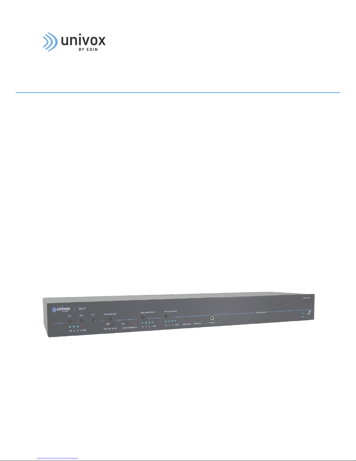
Univox® SLS-1/3/5
Class D Tech Series
State of the art phased array loop drivers
Univox® SLS-1 part no 221000
Univox® SLS-3 part no 223000
Univox® SLS-5 part no 225000
Page 2

2
Contents
Introduction ����������������������������������������������������������������������������������������������������������������������������������������������� 3
Univox® SLS-series ��������������������������������������������������������������������������������������������������������������������������� 3
SLS systems���������������������������������������������������������������������������������������������������������������������������������������� 3
Connections and controls ���������������������������������������������������������������������������������������������������������������������� 4
Overview ���������������������������������������������������������������������������������������������������������������������������������������������� 4
Description ������������������������������������������������������������������������������������������������������������������������������������������ 6
Installation ������������������������������������������������������������������������������������������������������������������������������������������������ 8
Planning ����������������������������������������������������������������������������������������������������������������������������������������������� 8
Tools required ������������������������������������������������������������������������������������������������������������������������������������� 8
Loop cable ������������������������������������������������������������������������������������������������������������������������������������������ 8
Placement of the driver ������������������������������������������������������������������������������������������������������������������� 8
Placement of the microphones ������������������������������������������������������������������������������������������������������ 9
Commissioning and certification ���������������������������������������������������������������������������������������������������� 9
Maximum recommended segment size (to comply with IEC 60118-4) ������������������������������� 9
System setup ������������������������������������������������������������������������������������������������������������������������������������������ 10
Start-up procedure�������������������������������������������������������������������������������������������������������������������������� 10
Input connection and adjustments ��������������������������������������������������������������������������������������������� 10
Output connection and adjustments ������������������������������������������������������������������������������������������ 10
Metal Loss Correction frequency setting ����������������������������������������������������������������������������������� 12
MLC function in maximum position ��������������������������������������������������������������������������������������������� 13
Trouble shooting ������������������������������������������������������������������������������������������������������������������������������������� 12
Safety �������������������������������������������������������������������������������������������������������������������������������������������������������� 14
Warranty ��������������������������������������������������������������������������������������������������������������������������������������������������� 14
Maintenance and care ��������������������������������������������������������������������������������������������������������������������������� 14
Service ������������������������������������������������������������������������������������������������������������������������������������������������������ 15
Technical data ���������������������������������������������������������������������������������������������������������������������������������������� 15
Environment �������������������������������������������������������������������������������������������������������������������������������������������� 15
Measuring devices ���������������������������������������������������������������������������������������������������������������������������������� 15
Univox® FSM 2�0, Field Strength Meter ��������������������������������������������������������������������������������������� 15
Univox® Listener, testing device ��������������������������������������������������������������������������������������������������� 15
The Installation Guide is based on the information available at the time
of printing and are subject to change without notice�
Page 3

3
Introduction
Univox® SLS-series
The Univox® SLS-serie phased array loop drivers combine 50 years of experience with
the newest electronic design to deliver unrivalled quality in a compact stylish housing�
In addition to the extraordinary sound clarity, power and performance, the outstanding
features for these cold amplifiers are low weight, small size and exceptionally high
efficiency� The high voltage follows the latest demands and statements in the
IEC 60118-4 standard, giving high quality sound for music as well as for speech�
The external power supply increases the total efficiency compared to traditional built-in
transformers� Our Engineering Simplicity philosophy is shown in the functionality and
usability of each model�
The three models SLS-1, SLS-3 and SLS-5 share the same features but with different
output power� Each offers 3 inputs - 2 of which are programmable - including a 100V line
input with priority option, a self-test mode, loop monitor and monitor speaker power driver�
With LED indicators for input and output levels, optimizing the system performance is easy�
SLS systems
SLS systems consist of two different loop systems, together creating a more controlled
field strength distribution with less overspill� They cover any size venue and transmit in
several direction removing the mute effect, common for standard loop systems, when
tilting head�
For the detailed information about SLS design, please study the Univox Loop Designer
(ULD) where several different approaches are visualized in 3-D simulation for a
comprehensive understanding�
Included in package
• Loop driver
• DC Power Supply
• Power cable
• 3 pcs of phoenix screw terminals
• 4 pcs of rubber feet (preassembled)
• T-Sign according to ETSI-standard
• Rack mounting plate with 8 screws
• DC Power supply mounting plate with 4 screws
• Certificate/Measuring protocol
• Installation guide
Page 4
4
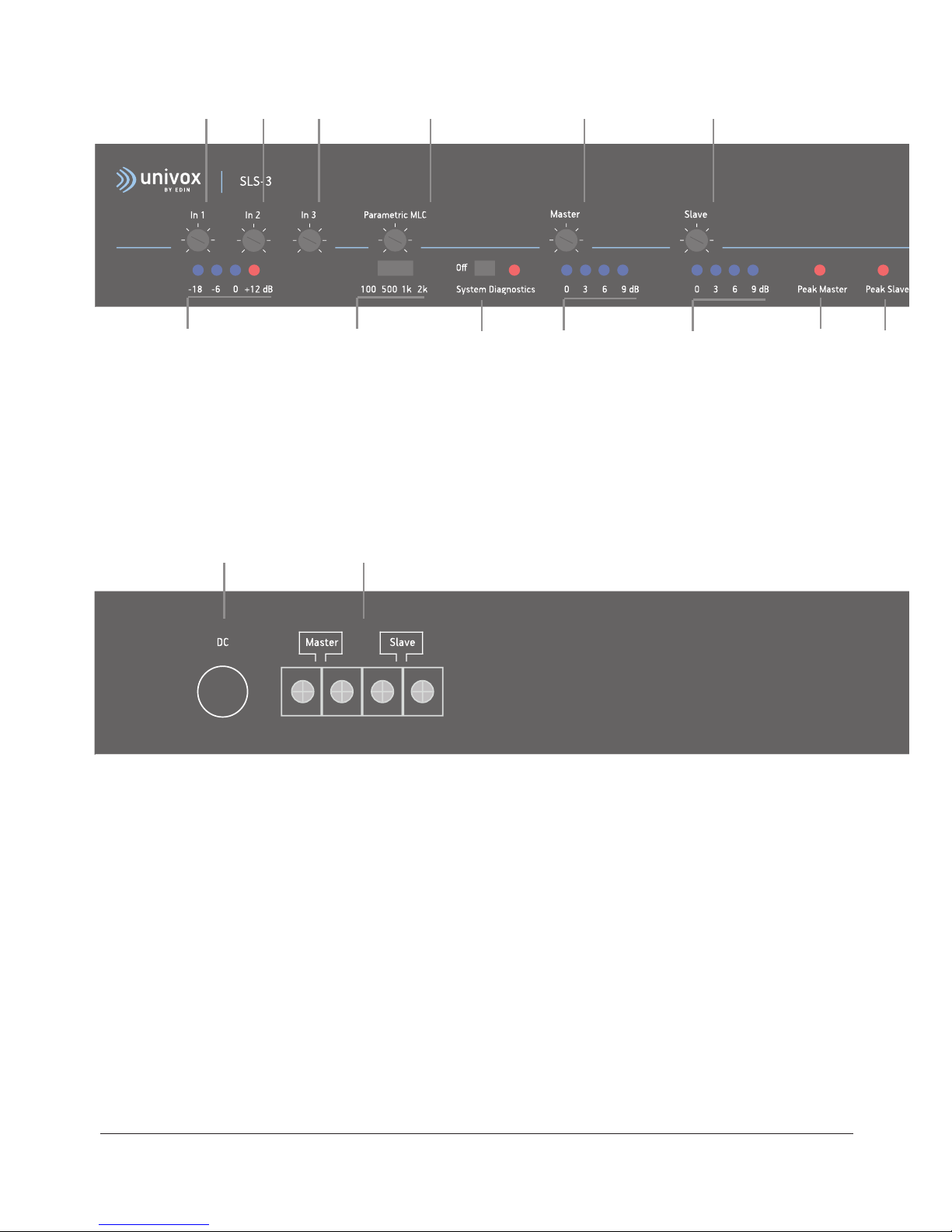
1� Input level potentiometers
2� Input level LED bar graph
3� Parametric MLC control
4� Parametric MLC knee point switch
5� System diagnostics switch and LED
1 1 1 3
2 4 5 7
6
7
6
8 8
11 12
11� DC supply input
12� Master/Slave loop connector
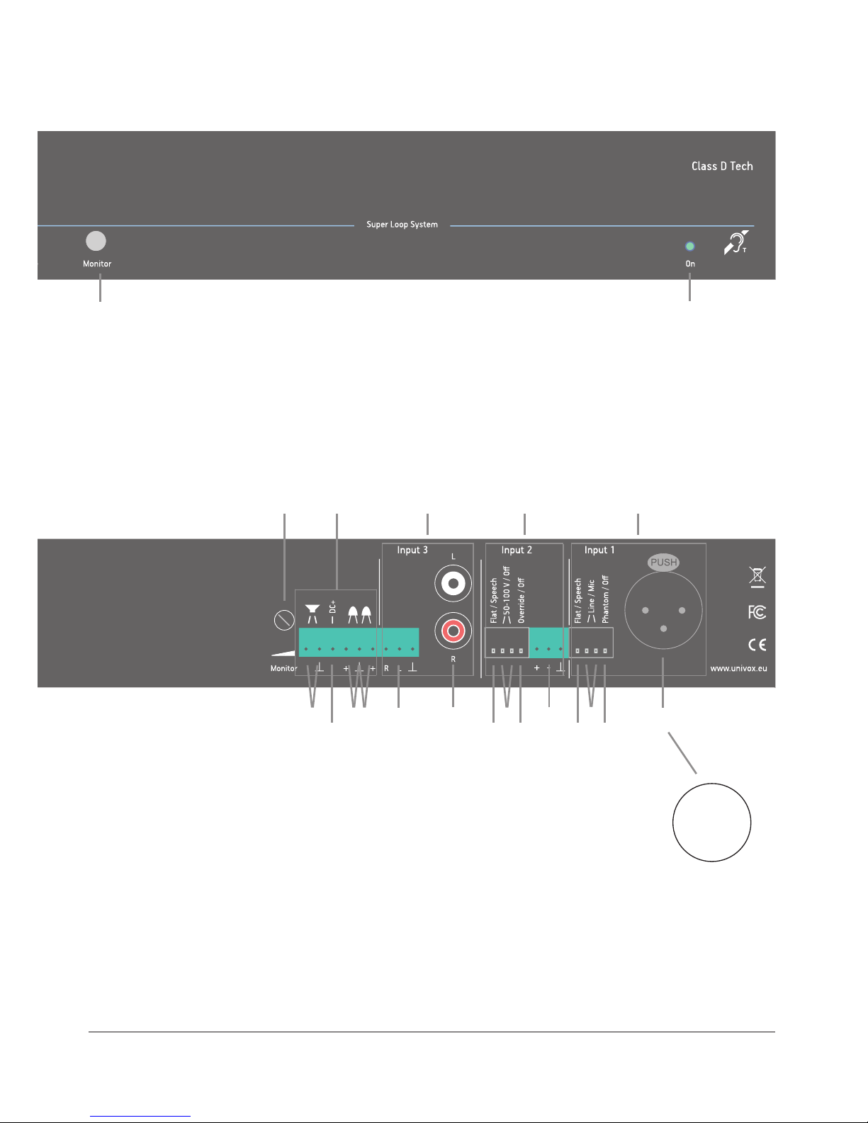
13� Monitor volume control for both headphones and speaker output
A. MISCELLANEOUS OUTPUTS
14� Monitor speaker connector
15� Auxiliary DC power output
16� Remote input monitor connector
17� Remote output monitor connector
B. INPUT 3
18� Phoenix screw terminal
19� Unbalanced RCA
Connections and controls
Overview
Page 5
5
6� Loop current potentiometers master/slave
7� Loop current led bar graphs
8� Peak LEDs Master/Slave
9� Loop monitor headphones socket
10� Power LED
9 10
13 A B C D
27
26
25
2422
21
20
19181716
15
14 23
C. INPUT 2
20� Speech enhancement switch (Flat/Speech)
21� 50-100 V Line switches On/Off
22� Override switch On/Off (Input 3)
23� Phoenix screw terminal
D. INPUT 1
24� Speech enhancement switch (Flat/Speech)
25� Line/Mic sensitivity switches
26� Phantom power voltage switch On/Off
27� Balanced XLR
• •
•
+
_
T
Page 6

6
Description
1-2� Input level should be set to 0 dB� (i�e� the 0 dB LED should be lit most of the time during the audio
programme� The +12 dB LED indicator should not be lit at any time�)
3-4� Parametric MLC control makes it possible to fine tune the frequency response, compensating for
the effects of different metal types and configurations�
There are 4 parametric curves starting from; 2 kHz, 1 kHz, 500 Hz and 100 Hz� These set the
frequency at which the metal loss correction control starts to compensate� The function is powerful,
however, excessive compensation can lead to signal limiting in the treble range� If signal limiting occurs,
the red peak LED illuminates�
5� System Diagnostics verify the integrity and function of the loop driver - inputs, output and the loop
condition�
Use: Set the switch on the front panel to right position� A built-in 1�6kHz signal pulses at 2 seconds
intervals at 0 dB, regardless of the adjusted sensitivity�
If input and output LEDs flashes in unison, the loop driver functions are verified�
If only the input LEDs flashes it indicates that the loop is not connected or the current potentiometer
needs to be readjusted��
Switch to le position Off, for normal use�
6� Loop current controls set the output current, i�e� the field strength of the loop�
7� Loop current LED bar graph indicates the level of the loop current, not the field strength� The field
strength is measured using a Field Strength Meter, like Univox FSM 2�0�
8� Peak (clip) LEDs illuminate when there is insufficient voltage to maintain a constant loop current�
Momentary short term voltage clipping is unlikely to be audible in hearing aids, but if clipping occurs for
any length of time (the Peak LED remains on) the audio quality will suffer�
Peak clipping will typically occur when using long thin wires, 2-turn loops and for signals with high
frequency spectrum, like modern music� Speech has a small amount of high frequency content� Strong
compensation from the parametric MLC control may increase the risk of clipping�
Note: use ULD for simulation guidance before installation and commissioning�
9,13,14 Loop Monitor, supports headphone (9) and speaker outputs (14) representing the sound quality of
the loop� Volume control for both headphones and speakers, is set by the potentionmeter (13)�
10� Power LED verifies power supply connection
11� 4 pin DC Supply socket for secure connection of Univox approved power supplies 90-260VAC, 50-60Hz,
only� Connect the power to the amplifier before connecting to the network, otherwise there is a risk of
sparking�
12� Loop scew terminals for Master and Slave loop connection
A. MISCELLANEOUS OUTPUTS PHOENIX SCREW TERMINAL (6 connectors/screws)
14� Monitor speaker connector
Pin 1+2 (2=GND), speaker output 8-32 Ω
15� Auxiliary DC power output 15V-24V depending on model
Pin 3+2 (2=GND), DC 12-18V output, 100mA
Page 7

7
16� Remote input monitor connector indicates at -6dB input level
Pin 4+5 (5=GND) = LED connection , indication/diagnostic test
17� Remote Output Monitor Connector indicates at 0 dB output level
Pin 5+6 (5=GND) = LED connection, indication/diagnostic test
B. INPUT 3 (PHOENIX SCREW TERMINAL/RCA)
18� Balanced Line: 30 mVrms-5Vrms (-28dBu to 17dBu)
19� Unbalanced RCA le/right
C. INPUT 2 (PHOENIX SCREW TERMINAL)
Switchable between line and 50-100V speaker line input
Note: The speaker line MUST be balanced at the Phoenix connector (connect (+) and (–) terminal)
Use earth ONLY for free-floating screen or leave unconnected
20� Speech filter: Low cut filter 130-170Hz On/Off
Speech Enhancement (Flat/Speech) attenuates low frequencies (<150Hz) increasing speech
intelligibility for microphone use
Note: When commissioning field strength level and frequency response this feature must be
switched to Flat postition
21� Speaker 50-100V balanced Line, sensitivity On/Off
Caution! 50-100 V/Line must be set prior to any further settings
22� Override/Priority function mutes inputs and is typically used for voice alarm systems� Signals higher
than -6dB on input 2 activates the priority function
23� Balanced Line: -15dBu (50mVrms) to +20�6dBu (8�3Vrms)
D. INPUT 1 (BALANCED XLR)
Balanced XLR� Switchable between Line and Mic sensitivity and with or without Phantom voltage
Note: With unbalanced connection (not recommended) the pin not used should be grounded�
24� Speech filter: Low cut filter 130-170Hz, On/Off
Speech Enhancement (Flat/Speech) attenuates low frequencies (<150Hz) increasing speech
intelligibility for microphone use
Note: When commissioning field strength level and frequency response this feature must be
switched to Flat position
25� Line/Mic sensitivity switches: -55dBu (1�5 mVrms) to +10dBu (2�6Vrms)
26� Phantom voltage 12V, On/Off
27� Balanced XLR
Page 8

8
Installation
Planning
Calculations for coverage area, metal loss, signal sources, power outlets, dissipating heat
and ventilation for loop driver placement and other practical installation issues, must be
done prior to the on-site installation� Please refer to www.univox.eu/planning
Use Univox Loop Designer (ULD), a free, web-based project planning and design tool that
quickly and accurately assists in the design of loop systems�
www.univoxloopdesign.org
Tools required
Copper tape tools, e�g� crimping tool, double-sided adhesive tape, printed warning tape
General audio installation tools, e�g� Ohmmeter
Field strength meter, e�g� Univox FSM 2�0
Listening device, e�g� Univox Listener
Loop cable
Always install a twin core loop cable to secure necessary connection options, especially
vital in environments with uneven metal loss� Univox twin core copper tape gives top
efficiency with low induction loss� Use a junction box to alternate between single, double
and twin turn loop connections�
Use a feed cable (twisted or twin wire) between the junction box and the loop driver, as
well as between the loop figuration and the junction box or loop driver�
Placement of the driver
The Univox SLS-1, SLS-3 and SLS-5 loop drivers will not generate any excessive heat and
can be mounted in 19" racks on top of or below other rack components (check that these
don’t generate excessive heat), on a wall or another flat surface� In a rack system it is oen
practical to attach the external power supply on the supporting metallic construction using
straps� For mounting of the wall, you need to open the chassi to get access to the holes�
Note: Although there are several built-in protection schemes for temperature, current and
power etc� we recommend to plan for worst case scenario�
Use general basic audio practice while installing and mounting units and wiring, including
loop cable� Avoid feedback interference between analog signal source cables and loop
cable� The loop cable mustn’t be placed closer than 30cm (12in) to a parallel microphone
or mixer cable� Crossing is ok�
Page 9

9
Metallic
environment
Basic level
(1000Hz)
IEC level
(1600Hz)
Field
Strength
Attenuation
Important notes/requirements
No metal 22m/70 22m/70 0
Standard
reinforced
concrete
7m/23 5m/16 3�5-6dB
Increased current, voltage and
power
Heavily
reinforced
concrete
5m/16 4m/13 3�5-6dB
Increased current, voltage and
power
Suspended
ceiling
4�8m/16 3,6m/12 4-10 dB
Conductor must be centered in the
suspended ceiling framwork (longest
distance to metal)
Increased current
Steel deck/
Metal system
floor
4m/13 3m/10 6-10dB Increased current
Iron bar
construction
3m/10 2m/6�5 4-12dB
Medium/strong damping, depending
on placement of wire (avoid
placement along metal bars)
Maximum recommended segment size (to comply with IEC 60118-4)
Placement of the microphones
Microphone placement and proximity between microphone and mouth is crucial for improved
speech intelligibility� Use shortest distance possible between microphone and mouth/sound
source�
Commissioning and certification
It’s important to check the system when the installation is completed� To ensure that the
loop installation meets the requirements for field strength, consistency and frequency
response, it must comply with the international standard IEC 60118-4�
A guide how to commission a loop system to the IEC performance standard, can be found
in the user guide for the Univox FSM 2�0 field strength meter and in the Univox® Certificate
of Conformity� These documents are also available on www�univox�eu/certify�
Page 10

10
System setup
Start-up procedure
1� Disconnect all input and output connections�
2� Each loop must be securely isolated (particularly to safety-ground and other loop
connections)� Verify the resistance of each loop (approximately 1-3 Ohm)�
3� Set all level controls to minimum setting:
• System Diagnostics
(5) = Off (switch to le position)
• Parametric MLC
(4) = 2kHz (switch to right position)
4� Connect the Power supply
(11) and verify Power LED indication (10)
5� Activate System Diagnostics by sliding the switch to the right� Input level bar graph
peaks (2) to 0dB � Output bar graph (7) does not indicate�
6� Connect Master loop
(12) and adjust the output level, making sure input and output
bar graphs indicate in unison� Note: a 2-turn loop is oen more efficient� See next page�
7� Check field strength for all loop segments using a field strength meter, e�g FSM 2�0�
Verify low field strength directly above wires and high in between segments (peaks to
approximately -2dB)� If not, there might be a local short circuit between wires�
8� Disconnect Master loop and connect Slave loop
(12). Repeat the procedure for Slave loop�
9� Basic function of the loop system is now verified� Turn System Diagnostics off, by
sliding the switch to the le�
10� Reconnect Master slave�
Input connection and adjustments
11� Set all level controls to minimum setting:
• System Diagnostic
(5) = Off (switch to le position)
• Parametric MLC
(4) = 2kHz (switch to right position)
12� Connect the main audio source to the amplifiers input (B, C or D)
13� Adjust input level (1) to 0dB at input bar graph (2)� If using a 1kHz pulsed sine wave
signal, simply set to 0dB�
Output connection and adjustments
14� Field strength setting: Start with the highest efficiency connection, I) 2-turn serial
connection, in junction box�
Page 11

11
15� Set field strength (6) to -3dB to 0dB at the peaks� If Peak (8) LED flickers only
momentarily the connection is acceptable� If Peak LED indicates continuously, try
rewireing the connections in the junction box in subsequent order: II) one wire single
turn and then
III) two parallel wires single turn�
With this procedure the unit will operate with the highest output possible without
generating any heat�
Note: To quickly set up the field strength for a real program source, a PPM instrument
is helpful� The Univox Listener has a calibrated level indicator that quickly finds the
highest peak�
Note: When adjusting the field strength peaks, -2dB field strength works best, due to
different dynamic headrooms in hearing aids�
16� Check basic frequency response according to IEC 60118-4, using a field strength meter,
e�g FSM 2�0� If necessary, follow Frequency adjustment procedure (see page 12)�
17� Check the sound quality by using an external listening device (Listener or FSM 2�0),
Monitor speaker connector
(14) or Monitor (9) for headphone (volume control on rear
panel Monitor (13))� When operating at maximum output on low impedance, i�e single
turn loops, the automatic limit protection circuit may cut programme peaks� This can
be avoided by changing to a 2-turn loop or reduce the output current setting�
18� Start the Commissioning process to certify the installation (see page 9)�
I) 2-turn serial
connection
II) one wire single turn III) two parallel wires
single turn
Page 12

12
Trouble shooting
Symptom Possible cause Solution
General malfunction - Check the system with the start-up
procedure� See page 10�
Power LED is off Power supply not connected
Power supply faulty
Connect power supply correctly
Replace power supply
Input and output LEDs
flash on and off
System Diagnostics turned on Turn System Diagnostics off
Output current LEDs are
off, input LEDs are on
Loop current turned down Adjust Loop current
Output and input LEDs
are off, power LED is on
No input signal
Input signal set too low
Check if input signal is present
Adjust level of input signal
Audio quality is poor,
peak LED indicates
Malfunction loop cable
Loop impedance is too high
Loop current set too high
Parametric MLC set too high
Rerun start-up procedure� (page 10)
Change the loop: use twin cores in parallel
or use a cable with higher cross-section
Turn loop current down
Turn down Parametric MLC
Audio quality is poor,
peak LED is off, sound
quality using headphone
monitor is also poor
Input signal set too high
Audio source is of poor quality
Reduce input signal level and check
Line/Mic level setting
Change/adjust audio source
Metal Loss Correction frequency setting
The degree of compensation for metal loss is adjusted with the MLC potentiometer (3)�
The start/break frequency is set with the Parametric MLC knee point switch (4) marked:
100Hz, 500Hz, 1kHz, 2kHz�
1� Start with the break frequency set to 2kHz�
2� Adjust the level to -12dB� If this is not sufficient, move to the next lower frequency and
repeat as required�
3� Verify that the loop driver’s voltage doesn’t saturate, i�e� that the peak indicator
(8) only
flickers temporarily�
Page 13

13
Symptom Possible cause Solution
Intelligibility of sound
from microphone is poor
Low frequency masking
Poor microphone user
techniques
Turn speech enhancement filter on
Instruct user/reduce speaking distance
Microphone connected,
input LEDs are off
Phantom power not turned on
Input level too low
Microphone needs higher
phantom voltage
Microphone/lead/connectors
faulty
Turn phantom power on
Increase input level/reduce speaking
distance
Use valid microphone or connect a
microphone mixer (amplifier)
Exchange faulty part
Alarm/priority signal is
not clear
Override DIL switch not set to
allow this function
Set DIL switch to correct position
Cannot achieve required
frequency response at
100 Hz
Speech enhancement filter
turned on
Turn speech enhancement filter off
Cannot achieve
required frequency
response at 5 kHz
Parametric MLC not set correctly
Frequency dependent losses
too high for parametric
compensation
Set Parametric MLC to correct level
Use smaller/multiple loops
MLC function in maximum position
0 dB
-5 dB
-10 dB
-15 dB
100 Hz
1 kHz
10 kHz
Page 14

14
Safety
The equipment should be installed by an audio visual technician observing 'good electrical
and audio practice' at all times and following all the instructions within this document�
Only use the power adapter supplied with the unit� If the power adapter or
cable is damaged, replace with a genuine Univox part�
Power adapter must be connected to a mains outlet close to the amplifier and
easily accessible� Connect the power to the amplifier before connecting to the network,
otherwise there is a risk of sparking�
The installer is responsible for installing the product in a way that may not cause risk of
fire, electrical malfunctions or danger for the user� Do not cover the power adapter or loop
driver� Only operate the unit in a well ventilated, dry environment�
Do not remove any covers as there is a risk of electric shock� There are no user
serviceable parts inside� Refer servicing to qualified personnel� Please observe
that the product warranty does not include faults caused by tampering with the
product, carelessness, incorrect connection/mounting or maintenance�
Bo Edin AB shall not be held responsible or liable for interference to radio or TV equipment,
and/or to any direct, incidental or consequential damages or losses to any person or
entity, if the equipment has been installed by unqualified personnel and/or if installation
instructions stated in the product Installation Guide have not been strictly followed�
Warranty
This loop driver is supplied with a 5 year (return to base) warranty�
Misuse of the product in any way including but not limited to:
• Incorrect installation
• Connection to non-approved power adapter
• Self oscillation resulting from feedback
• Force majeure e�g� lightning strike
• Ingress of liquid
• Mechanical impact
will invalidate the warranty�
Maintenance and care
Under normal circumstances the product does not need any special maintenance�
Should the unit become dirty, wipe it with a clean damp cloth� Do not use any solvents or
detergents�
Page 15

15
Service
Should the system not work as expected, please follow Checklist for installation found on
www�univox�eu/support or contact the local distributor for further instructions�
Before returning a product to us for service you will need a Service Number from your
distributor� They will also send you a Service Report Form which must be completed and
returned with the product�
Technical data
For additional information, please refer to product data sheet and CE certificate which can
be downloaded from www�univox�eu/products� If required, other technical documents can
be ordered from support@edin�se�
Environment
To prevent possible harm to the environment and human health, please dispose of the
product responsibly by following statutory disposal regulations�
Measuring devices
Univox® FSM 2.0, Field Strength Meter
Professional instrument for measurement and certification of
loop systems in accordance with IEC 60118-4�
Univox® Listener, testing device
Loop receiver for fast and simple check of the sound quality and basic
level control of the loop�
Page 16

Hearing excellence since 1965
(Univox) Bo Edin AB
Stockby Hantverksby 3,
SE-181 75 Lidingö, Sweden
+46 (0)8 767 18 18
info@edin.se
www.univox.eu
sls-1-3-5-ig-gb- 170220 Copyright © Bo Edin AB
 Loading...