

Page 1
UniVox® Super Loop System
®
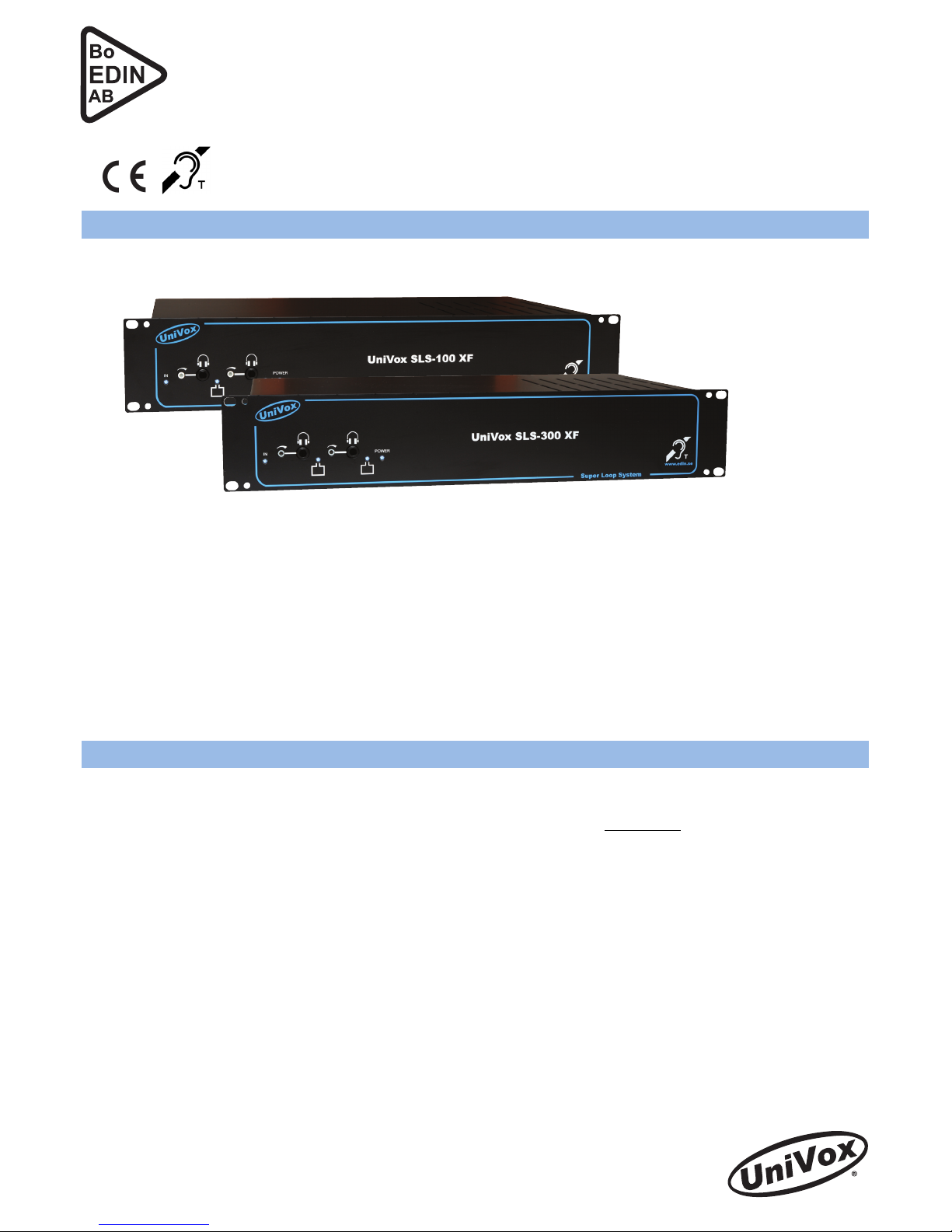
SLS-100 XF / SLS-300 XF
Loop amplier for balanced loop congurations
Installation Guide
Bo EDIN AB • Stockby Hantverksby 3 • SE-181 75 Lidingö • SWEDEN
Phone +46 8 7671818 • Fax +46 8 7671820 • www.edin.se • info@edin.se
Free eld coverage area up to 170m²/300m² according to IEC 60118-4:2006
UniVox® SLS – Super Loop System® is target designed for
professional installations in venues where high sound quality
for the hearing aid user, very high reproducibility together
with extremely low overspill in all directions are important
requirements. Through correct calculations, installation and
adjustment you will get 3-D controlled overspill, smooth eld
strength even at high frequencies, little interference problem
with reinforcement and other metallic structures as well as
increased efciency compared to traditional loop systems.
UniVox® Super Loop System® – SLS-100 XF (Part No 215100) / SLS-300 XF (Part No 215300)
Note! Please study the complete installation guide before planning, connecting and adjusting the loop system!
The result for all hearing aid users is a loop of HiFi quality!
For areas up to 650m² use UniVox® SLS-700 (two separate
units).
UniVox® SLS fulls IEC 60118-4:2006 when installed and
adjusted correctly.
Loop wire layout and other preparations
● Each UniVox® SLS system has to be planned carefully to work correctly. A complete system always consists of two
separate loop congurations - Master and Slave. The Master and Slave loop work as one single system and has to be
planned together. For further information or assistance, please contact us through www.edin.se or contact your local
distributor.
● We highly recommend the special designed copper foil (25 x 0.1 mm) giving an increased high frequency response of
approximately 5 dB compared to a conventional round wire. The copper foil can be used with any loop size and will t
easily under plastic or textile carpets, wooden oor or tiles. Always check with the material experts/suppliers for detailed
advice.
● When using round standard wire we recommend 4 mm² for most applications. For smaller loops a thinner wire can be
used. Please contact us or your local distributor by any uncertainties.
● Field strength and high frequency response can be limited due to reinforcement and metal constructions in walls, ceiling
and oor. Therefore it is important NOT to place the wire near/parallel to or on metal constructions or reinforcement
(crossings are allowed). If there is strong metallic inuence it might be necessary to choose a more powerful amplier,
even if the listening area normally should be covered by the amplier you have chosen.
● Use general installation technique for audio/video installations. Pay extra attention to avoid interference problems with
sensitive analogue signals from microphones, mixers, video projectors etc. Avoid parallel wires close to the loop wire.
● Plan other electronic controlled equipment avoiding or creating any disturbing magnetic elds.
Page 2

2
Connection and function control
Mount the amplier in a 19" rack, place it on a at surface or mount it on a wall using the keyholes underneath.
Important!
The amplier needs free airow above and beneath the amplier. It is important NOT to place the amplier close to any
inammable material sensitive to heating or any material running the risk of getting discoloured. If placed on at surface or
wall mounted, use the rubber feet included in the box. The keyholes only admit horizontal mounting of the amplier.
1. Inputs Set all inputs to min. settings. Connect the input signal to corresponding input connector at the
rear panel. The combined XLR/6.35mm input is factory set for line input levels but could be set
for microphone use (see “jumper settings” section below). The SCART connectors are used for
TV and other SCART devices. The built-in Autoscart switching will ensure that the sound from
the active SCART device is connected to the loop system.
2. Mains power Power the amplier with the included power cord (power indicator lights up). UniVox® ampliers
are equipped with a reset able built-in automatic mains fuse, type PTC. If it is triggered by any
reason remove the power cord and let the amplier cool off. Investigate the possible fault reason
before reconnecting the power cord.
3. Adjust inputs Slowly adjust the inputs making the LED input indicator on the front side lights up at program
peaks.
4. Connect the loop wire Connect the loop wires to the corresponding loop output, Master or Slave. Note the wire between
loop guration and amplier must be twinned or very tight together to avoid interference with
other electrical systems.
5. Adjust loop current Adjust the loop current for correct eld strength on both Master and Slave loop according to
the certicate protocol (the loop LED only indicates that current ows in the loop wire). Use
the adjustable loop monitor outputs on the front panel for direct listening of the output current
(magnetic eld).
Attention!
The loop LED indicates that current ows in the loop, not that system fulls the standard,
IEC 60118-4:2006. See ”Measurement and certication” below.
Line outputs
There are two line outputs with RCA connectors giving 0 dBu with AGC-controlled level.
Measurement and certication
Attention!
Make sure that the amplier is disconnected from the mains power before removing the cover.
Jumper settings related to XLR-input
Phantom power off: S3 open (Default). Phantom power on: S3 closed.
Microphone sensitivity: S1 and S2 open. Line sensitivity: S1 and S2 closed (Default).
Input AGC
AGC on (Default): S4 closed. AGC off: S4 open.
A complete and correct measurement, adjustment and certication of the UniVox® SLS system is achieved using the True
RMS Field strength meter FSM together with the certicate/measuring protocol (included). For detailed measurement
procedures please study the certicate. A complete certicate shall always be included in the documentation.
It is important that the staff responsible for the loop system has the necessary knowledge how the loop system works.
Otherwise there is a risk that the system doesn’t work as planned.
The loop receiver/testing device UniVox® Listener is a useful device for listening tests and basic level checks.
Jumper settings for sensitivity, phantom voltage and AGC-function
Page 3

3
Connection mains power
Loop connection
Master
Loop current
controls
Input 2
Input 1
Line outputs with
AGC function
Loop connection
Slave
Scart connections
Input adjustments
UniVox® FSM
Field strength meter
UniVox® Listener
Testing device
WARNING!
LIVE TERMINALS ENCLOSED
Always disconnect mains power before the
amplier is opened
XLR input
Balanced
Unbalanced
Signal to pin 2 or 3
Signal to pin 2 and 3
ShieldShield
Loop connections
Indicator
input signals
Indicator
Master loop
Indicator
mains power
Indicator
Slave loop
Loop monitor, Master/Slave
Page 4

SLS-100_300XF_IgGb_111014.indd Copyright © Bo Edin AB
UniVox® Super Loop System® SLS is a balanced
uncorrelated induction loop system. It consists of two
separate loop systems (Master and Slave) with a separate
current controlled ampliers connected to each loop.
UniVox® SLS systems have several advantages compared to
old conventional loop systems:
● Almost no vertical and horizontal overspill
● Smoother eld strength level
● Highly increased frequency response
● Less impact on eld strength and high frequency range
by reinforcements or other metal construction parts
● Less directional sensitivity (no level drops when tilting
the head)
● Increased efciency due to controlled eld strength
● Highly reduced risk for interference with other
electronic equipment, guitars, microphones, etc.
There are many possibilities for the layout of the loop wire,
but the basic UniVox® SLS system for most installations
is the same: A Master loop which covers the whole
listening area and a Slave loop, slightly smaller compared
to the Master loop. The size of the segments controls the
overspill, both horizontal (sideways) and vertical (sitting
vs. standing). In theatres or cinemas the segment size is
simply the same as the distance between the seating rows
for ease of installation (with UniVox® SLS there is no eld
strength drop above the crossing of the wires). 1 meter
segment size is normally ne but other segment sizes could
be recommended depending on the installation.
After the installation of wire and loop amplier, the whole
system has to be certied. Both installation and adjustment
has to be performed by trained staff equipped with a eld
strength meter and basic knowledge of how the system
works and how loops are measured and adjusted. Contact
your distributor for all questions regarding projection,
installation and adjustment of the system. You can nd more
information at www.edin.se where also a drawing tool for
planning is available on-line (contact your distributor for
log-in data).
The UniVox® SLS example on the right is created with the
above mentioned on-line planning tool on our web site. It
is recommended that the direction of attention or “looking
direction” should preferably be across the segments. The
size is 12 by 8 metres with 8 segments and thus a segment
size of 1,5 m. The amount of wire needed for the Master
and Slave loops is indicated at the bottom of each drawing.
Layout of a Master loop
Layout of a Slave loop
Phone
+46 8 7671818
Fax
+46 8 7671820
E-mail
info@edin.se
Website
www.edin.se
Bo EDIN AB
Stockby Hantverksby 3
SE-181 75 LIDINGÖ
Sweden
The SLS system – a summary
Final result - both loops shown at the same time
 Loading...