

Page 1
1
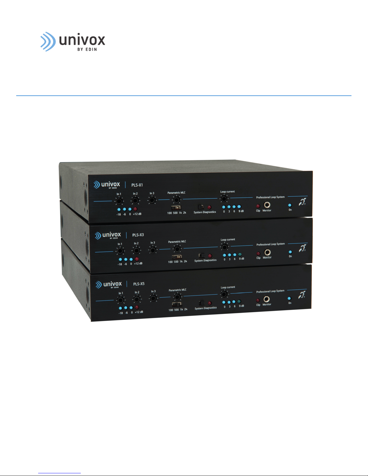
Univox® PLS-X1, X3, X5
Induction Loop Drivers
Installation Guide
Univox® PLS-X1 Part No 217100
Univox® PLS-X3 Part No 217300
Univox® PLS-X5 Part No 217500
Page 2

2
Content
Introduction ..................................................................................................................... 4
Package contents ........................................................................................................... 4
Connections and controls ............................................................................................. 5
1. Input level control ............................................................................................. 6
2. Input level LEDs................................................................................................... 6
3-4. Parametric MLC ............................................................................................... 6
5. System Diagnostics ............................................................................................ 7
6. Loop Current Control .......................................................................................... 7
7. Loop Current LEDs .............................................................................................. 7
8. Voltage Clipping/Peak LED ................................................................................ 8
9. Loop Monitor/Headphones Socket.................................................................. 8
10. Power LED .......................................................................................................... 8
11. Loop Terminals.................................................................................................. 9
12. DC Supply socket .............................................................................................. 9
13. Monitor Speaker Connector (screw 1+2) .................................................... 9
14. Auxiliary DC Power Output (screw 3) ........................................................... 9
15. Remote Input Monitor Connector (screw 4+5) .......................................... 9
16. Remote Output Monitor Connector (screw 5+6) ..................................... 10
17. Monitor Volume Control ................................................................................10
18. Input Power Amplifier (In Pow Amp) .......................................................... 10
19. Output Pre-amplifier (Out Pre Amp) ........................................................... 10
20. Input 3 ..............................................................................................................11
21. Input 2 ..............................................................................................................11
22. Speech Enhancement (Flat/Speech) DIP Switch 1 ................................. 11
23. 50-100 V/Line DIP Switch 2 + 3 .................................................................. 11
24. Override On/Off DIP Switch 4 .......................................................................12
25. Input 1 ..............................................................................................................12
26. Speech Enhancement (Flat/Speech) DIP Switch 1 ................................. 12
27. Line/Mic DIP Switch 2 + 3 ............................................................................. 13
28. Phantom Power/DIP Switch 4 ...................................................................... 13
Page 3

3
Prepare installation .....................................................................................................14
Planning ................................................................................................................... 14
Tools required.........................................................................................................14
Loop cable ..............................................................................................................14
Placement of the driver .......................................................................................15
Placement of the microphones .......................................................................... 15
Maximum recommended segment size (to comply with IEC 60118-4) ...15
Installation ..................................................................................................................... 16
Start-up procedure ......................................................................................................16
Input connection and adjustments ..........................................................................16
Output connection and adjustments .......................................................................17
Metal Loss Correction frequency setting ................................................................18
MLC function in maximum position .......................................................................... 18
Commissioning and certification ............................................................................... 18
Default Settings ............................................................................................................ 19
Rear panel ............................................................................................................... 19
Front panel .............................................................................................................. 19
Trouble shooting...........................................................................................................20
Technical Specification ...............................................................................................22
Audio Input 1 .......................................................................................................... 22
Audio Input 2 ......................................................................................................... 22
Input 3 .....................................................................................................................22
In Pow Amp ............................................................................................................ 23
Out Pre Amp ...........................................................................................................23
Loop output ........................................................................................................... 23
Supplementary Outputs ....................................................................................... 23
Safety .............................................................................................................................. 24
Warranty ......................................................................................................................... 24
Maintenance and care ................................................................................................. 25
Service ............................................................................................................................25
Technical data ............................................................................................................... 25
Environment .................................................................................................................. 25
Measuring devices .......................................................................................................26
Notes .............................................................................................................................. 27
The Installation Guide is based on the information available at the time
of printing and are subject to change without notice.
Page 4

4
Introduction
Thank you for choosing Univox.
The new Univox
®
PLS-X series loop drivers combine 50 years of experience with the latest
in electronic design to deliver unrivaled sound clarity, power and performance in a compact
stylish housing.
Our Engineering Simplicity philosophy is evident in the functionality and user-friendliness for
each model.
The three models in the series, PLS-X1, PLS-X3 and PLS-X5 are identical with the exception
of output power. Each model offers three inputs, two programmable, including a 100V line
setting, a self-test mode, loop- and speaker amplifier monitor. With LED indicators for input
and output levels, optimizing system performance is simple.
The PLS-X Series is integrated into Univox
®
Loop Designer, a free, web-based project planning
and design soware, enabling fast and accurate configuration of induction loop systems.
Please read this user guide carefully before installation and usage of this product. All Univox
®
loop drivers have a very high output power resulting in products capable of fulfilling standards.
Package contents
The PLS-X series package contains the following components:
• Loop driver
• DC Power Supply
• Power cable
• Three phoenix screw terminals
• Four rubber feet
• T Sign
• Rack mounting plate with 8 screws
• Measuring protocol/certificate
• Installation Guide
Page 5

5
Connections and controls
PLS-X5
Loop current
Monitor
-6
Parametric MLC
In 1
In 2 In 3
Professional Loop System
0 +12 dB
Clip
System Diagnostics
-18
On
0 3 6 9 dB
100 500 1k 2k
Off
1. 1. 1.
2. 4.
5. 7.
6.
8. 9. 10.
1. Input level control (Input 1-3)
2. Input level LEDs
3. Parametric MLC control
4. Parametric MLC knee point switch
5. System diagnostics switch and LED
6. Loop current control
7. Loop current LEDs
8. Voltage clipping/Peak LED
9. Loop monitor jack
10. Power LED
11. Loop terminals
12. DC supply jack
13. Monitor speaker connector (screw 1+2)
14. Auxiliary DC power output (screw 3)
15. Remote input monitor connector (screw 4+5)
16. Remote output monitor connector (screw 5+6)
17. Monitor volume control
18. Direct connection to loop power amplifier
(In Pow Amp)
19. Pre-amplifier output (Out Pre Amp)
20. Input 3 (Phoenix screw terminal/RCA)
21. Input 2 (Phoenix screw terminal)
22. Speech enhancement DIP switch
(Flat/Speech)
23. 50-100 V line DIP switch On/Off
24. Override DIP switch On/Off (Input 3)
25. Input 1 (Balanced XLR)
26. Speech enhancement DIP switch
(Flat/Speech)
27. Line/Mic sensitivity DIP switch
28. Phantom power On/Off
DC+
In Pow
Amp
Input 2
Input 1
LR
+ -
L
R
www.univox.eu
Flat / Speech
Override / OFF
Flat / Speech
Phantom / OFF
Monitor
Out Pre
Amp
+
PUSH
+
50-100 V / OFF
Line / Mic
Input 3
-
+
C
12.
11. 17.
13.
14.
15.
16.
18.
19.
20.
21.
28.
27.
26.
24.
23.
22.
25.
3
Page 6

6
Explanation
Note
Univox PLS-X series is operational only if a loop cable is connected to the driver. Otherwise,
the Peak indicator is lit constantly as a warning.
All controls are regulated with a small screwdriver.
1. Input level control (In1-In3)
Each input can be set to correct input by appropriate single-turn potentiometer located on
the front panel.
2. Input level LEDs
The thee blue and single red LEDs indicate the signal level at the output of the preamplifier.
To ensure the AGC function is optimised, the signal level should be set to 0dB with
maximum peaks reaching +12dB, i.e. the 0dB LED should be lit most of the time during the
audio programme and the +12dB indicator should flicker occasionally.
3-4. Parametric MLC
The parametric metal loss control function enables system frequency response correction
in cases where the signal strength is strongly influenced by the surrounding metal. By
selecting an appropriate parametric curve, the installer can fine tune the frequency
response, compensating for the effects of different metal types and configurations.
Four options for parametric compensation can be selected: 2kHz, 1kHz, 500Hz and 100Hz.
The chosen curve sets the frequency at which the metal loss control starts to compensate.
The function is powerful, however, excessive compensation can lead to signal limiting in
the treble range. If signal limiting occurs, the red Peak LED (8) will illuminate indicating
that the signal is limited, i.e. the available voltage in the driver is insufficient to deliver a
constant current (voltage clipping).
Page 7

7
5. System diagnostics
Univox PLS-X series has a built-in system test. We recommend that this feature is used
periodically, at least monthly, to check the integrity of the loop driver, its inputs and the
loop condition.
To access the system diagnostics mode, set the switch on the front panel to the right.
All the inputs are now disabled and an internal 1kHz oscillator is connected to the input
instead. The oscillator pulses at 2 seconds intervals with a 0dB level, activating the AGC
regardless of the adjusted sensitivity. The red LED indicator is flashing with the signal.
If the input level LEDs and at least one output loop current LED flash in unison, the system
is working correctly.
If the input and output LEDs do not flash, check that the loop is connected and not open circuit.
Also check the proper connection of the signal source.
If only the input LEDs flash, and the loop is properly connected, the output current is set
too low. Increase the output current.
6. Loop current control
The loop current can be adjusted by turning the loop current control (6) potentiometer.
7. Loop current LEDs
The current output level is indicated by the loop current LEDs in 3dB increments. The LED
dB scale is relative to the loop output current and is based on the available current of
the particular model. 0dB is lit when the output current is 1/4 of the maximum available
current and the power is 1/8 of the available power. Each 3dB increment represents a
doubling of the output. However, the only way to set the output level to the correct IEC
level is to use a professional field strength meter, preferably Univox FSM 2.0.
Page 8

8
8. Voltage clipping/Peak LED
The Peak LED will illuminate when the voltage is clipping, i.e. there is insufficient voltage to
maintain a constant current.
Momentary short term voltage clipping is unlikely to be audible in hearing aids, but if
clipping occurs for any length of time (the Clip LED (8) remains on), the audio quality will
suffer and remedial action should be taken to reduce or eliminate the problem.
Voltage clipping will occur at higher frequencies first. It causes distortion of the audio
signal. Situations that require higher voltages from the loop driver and where voltage
clipping may occur are typically where:
• The loop has a high impedance. The impedance of the cable is determined by its length
and cross sectional area. The longer and thinner the cable, the higher its impedance.
The feed cable must also be considered when calculating the loop impedance. A 2-turn
loop will have an impedance more than double that of a single turn loop of the same
length and cross-section due to mutual inductance.
• Strong compensation from the parametric MLC control is applied
Note
In some cases metal reinforcement can actually reduce the voltage requirement.
9. Loop monitor/headphones socket
Univox® PLS-X series has a powerful speaker amplifier and a 3.5mm headphone socket
built-in. The headphone socket is on the front panel, the speaker connectors (13) and
volume control (17) are placed in the rear panel. Both are fed directly from the loop
providing an accurate reproduction of the loop signal. A distorted, poor quality signal or
lack of audio input is easily identified by use of this feature.
Note 1
The volume control is located in the rear panel and controls the volume level of both the
external speaker, if attached, and the headphones output.
Note 2
Excessive output to speaker may reduce the overall loop output power.
10. Power LED (On)
The blue Power LED is illuminated at all times when the unit is connected to a working
power supply.
Page 9

9
The units are designed to run 24/7. They do not have a separate on/off switch and can only
be turned off by disconnecting or turning off the power supply.
11. Loop terminals
The two outer terminals (screw 1 and 4) are used for connecting a single turn loop. The
two inner centre terminals (screw 2 and 3) provide a shorting bar to couple a 2-turn loop
when a twin core cable is used (see page 14).
12. DC Supply socket
The external DC power supply provided with the loop driver is connected at the DC supply
socket in the rear panel.
Note
Connect the power cord to the amplifier first, before connecting to the wall socket to avoid
high inrush current.
The voltage rating of the supply is dependent on the model.
Only Univox approved power supplies correctly rated for the loop driver model should be
used. The use of incorrectly rated, or third party power supplies will invalidate your 5 year
warranty.
13. Monitor speaker connector (screw 1+2)
A monitor speaker may be permanently connected providing some sound reinforcement in
smaller rooms. In this case, care needs to be taken to avoid acoustic feedback.
14. Auxiliary DC power output (screw3)
The DC output is available to power compatible accessories. The output voltage is
dependent on the loop driver model/external power supply.
15. Remote input monitor connector (screw 4+5)
A LED connected to this terminal will mirror the operation of the -6 dB input Level LED on
the front panel, thus allowing the monitoring of the presence of an input signal in a more
convenient location.
Page 10

10
16. Remote output monitor connector (screw 5+6)
A LED connected to this terminal will mirror the operation of the 0dB output current Level
LED on the front panel, thus allowing the monitoring of the presence of output current in a
more convenient location.
17. Monitor volume control
Controls the volume for the headphone output and the external speaker where fitted.
See (9) Loop Monitor and (13) Monitor Speaker Connector.
18. Direct connection to loop power amplifier (In Pow Amp)
An external signal source can be connected to the input and directly drive the loop
amplifier's power amplifier without effecting the amplifier's filter and AGC functions.
Typical connection: External DSP for direct control of frequency distribution and dynamic.
Input sensitivity: 0dBu (0.775V/10kOhm).
Note 1
The loop amplifier's other inputs (In1-In3) can be used simultaneously.
Note 2
This input lacks the 5kHz lowpass filter and is unballaned. Input impedance: 10kOhm
19. Pre-amplifier output (Out Pre Amp)
This output delivers an output signal aer adjustment of input level, filter and AGC functions.
Typical connections:
• Connection to recording devices with the built-in AGC function as level control
• Connection to a PA system (for example a mixer)
• Output signal to another loop amplifier through its RCA input (see 20)
Note
Connection of several loop amplifiers from one signal source is most easily done by connecting the signal in parallel to the balanced input (In1 or In2) of each amplifier. Each
amplifier is then individually adjusted with MLC and frequency adjustment.
Output level: approx. 0.5V.
Page 11

11
Input 2
+ -
Flat / Speech
Override / OFF
50-100 V / OFF
24
23
22.
20. Input 3
Input 3 is an unbalanced line input. The sensitivity is adjusted using
the control on the front panel.
The source may be connected using the RCA connector (L/R) or the
Phoenix screw terminal, but can't be used simultaneously.
If the RCA input is used:
Mono signals are connected through R or L and the earth connection.
Stereo signals are connected through R and L and the earth connection.
21. Input 2
Input 2 is a line input, switchable between a balanced line input and
a 50-100V line input. The sensitivity is adjusted using the control on the
front panel.
The source is connected using the Phoenix screw terminal:
Mono signals are connected to + or - and the earth connection.
Stereo signals are connected to + and - and the earth connection.
22. Speech enhancement (Flat/Speech) (DIP switch 1)
The speech enhancement function works by filtering low frequencies (<150Hz) which can
mask the intelligible sound. It is recommended to use this function for all normal loop
systems.
With the DIP switch in the ‘down’ position, speech enhancement is OFF.
With the DIP switch in the ‘up’ position, speech enhancement is ON.
Note
When commissioning the loop system in accordance with the performance standard IEC
60118-4, the speech enhancement function must be switched off.
23. 50-100 V/Line (DIP switch 2+3)
With both DIP switches in the ‘down’ position: Input 2 is set to 50-100V line sensitivity.
With both DIP switches in the ‘up’ position: Input 2 is set to "normal" line sensitivity.
For sensitivity levels, see technical specification on page 22-23.
LR
L
R
Input 3
Page 12

12
Note
The DIP switches should be set in the appropriate position before connecting the input
signal to avoid causing damage to the input.
24. Override On/Off (DIP switch 4)
With the DIP switch in ‘down’ position, Input 2 is set as the Priority Input.
In this case, when a signal is detected, all other inputs will be suppressed.
Only signals above -6dB activates the priority function. This functionality is
ideal when connecting to an alarm system such as a voice alarm.
To turn off this feature, set the DIP switch to the ‘up’ position.
25. Input 1
Input 1 is a balanced switchable Line/Mic input that can be set to
line or microphone sensitivity and with or without phantom power.
The sensitivity is adjusted using the control on the front panel.
Note
If connecting an unbalanced signal (not recommended) the pin
that is not used has to be connected to pin 1 (earth).
26. Speech enhancement (Flat/Speech) (DIP switch 1)
The speech enhancement function works by filtering low frequencies (<150Hz) which can
mask the intelligible sound through the so called "masqing effect". It is recommended to
use this function for all normal loop systems.
With the DIP switch in the ‘down’ position, speech enhancement is OFF.
With the DIP switch in the ‘up’ position, speech enhancement is ON.
Note
When commissioning the loop system in accordance with the performance standard IEC
60118-4, the speech enhancement function must be switched off.
Input 1
Flat / Speech
Phantom / OFF
PUSH
Line / Mic
28
27
26.
Input 2
+ -
Flat / Speech
Override / OFF
50-100 V / OFF
24
23
22.
Page 13

13
27. Line/Mic (DIP switch 2+3)
The switch is used to alter the sensitivity of the XLR input for line and microphone.
With the 2 DIP switches in the ‘down’ position, Input 1 is set to Line sensitivity.
With the 2 DIP switches in the ‘up’ position, Input 1 is set to Mic sensitivity.
For sensitivity levels, see Technical Specification on page 22-23.
28. Phantom Power On/Off (DIP switch 4)
Electret microphones need a DC bias to function. This DC bias, when provided by the host
amplifier, is commonly called phantom power.
With the DIP switch in the ‘down’ position phantom power is turned ON.
With the DIP switch in the ‘up’ position, phantom power is turned OFF.
The phantom power or bias voltage is approximately 12V (some variation occurs,
depending on the loop driver model).
Note 1
Phantom Power should only be turned on when an electret microphone is connected to the
amplifier.
Note 2
Before connection of an electret microphone needing more phantom power than 12V, a
microphone pre-amplifier must be used. If such a pre-amplifier is connected to the XLR
connector in Input 1, the phantom power should be turned off (switch 4 in 'up' position)
and the sensitivity be set to line level (switch 2+3 in 'down' position).
Page 14

14
Prepare installation
Planning
Calculations for coverage area, metal loss, signal sources, power outlets, dissipating heat
and ventilation for loop driver placement and other practical installation issues, must be
done prior to the on-site installation. Please refer to www.univox.eu/planning
Use Univox Loop Designer (ULD), a free, web-based project planning and design tool that
quickly and accurately assists in the design of loop systems.
www.univoxloopdesign.org
Tools required
• Copper tape tools, e.g. crimping tool, double-sided adhesive tape, printed warning tape
• General audio installation tools, e.g. Ohm meter
• Field strength meter, e.g. Univox FSM 2.0
• Listening device, e.g. Univox Listener
Loop cable
Always install a twin core loop cable to secure necessary connection options, especially
vital in environments with uneven metal loss. Univox twin core copper tape gives top
efficiency with low induction loss. Use a junction box to alternate between single, double
and twin turn loop connections.
Use a feed cable (twisted or twin wire) between the junction box and the loop driver, as
well as between the loop figuration and the junction box or loop driver.
1-turn loop
2-turn loop with dual core cabel
Fig 3.
Page 15

15
Metallic
environment
Basic level
(1000Hz)
IEC level
(1600Hz)
Field Strength
Attenuation
Important notes/requirements
No metal 22m/70 22m/70 0
Standard
reinforced
concrete
7m/23 5m/16 3.5-6dB Increased current, voltage and power
Heavily
reinforced
concrete
5m/16 4m/13 3.5-6dB Increased current, voltage and power
Suspended
ceiling
4.8m/16 3,6m/12 4-10 dB
Conductor must be centered in the
suspended ceiling framwork (longest
distance to metal)
Increased current, decreased power
Steel deck/
Metal system
floor
4m/13 3m/10 6-10dB Increased current, decreased voltage
Iron bar
construction
3m/10 2m/6.5 4-12dB
Medium/strong damping, depending
on placement of wire (avoid
placement along metal bars)
Maximum recommended segment size (to comply with IEC 60118-4)
Placement of the driver
The Univox PLS-X loop drivers will not generate much excessive heat and can be mounted
in 19" racks on top of or below other rack components (check that these don’t generate
excessive heat), on a wall or another flat surface. In a rack system it is oen practical to
attach the external power supply to the supporting metallic construction using straps. For
mounting on the wall you need to open the chassis to get access to the mounting holes.
Note
The power supply must be connected to a wall socket close to the loop amplifier.
Although there are several built-in protection schemes for temperature, current and power
etc. we recommend to plan for worst case scenario.
The loop cable mustn’t be placed closer than 30cm (12in) to a parallel microphone or
mixer cable. Crossing is ok.
Placement of the microphones
Microphone placement is crucial for speech intelligibility. Use shortest distance possible
between microphone and mouth/sound source.
Page 16

16
Installation
Start-up procedure
1. Disconnect all input and output connections.
2. Each loop must be securely isolated (particularly to safety-ground and other loop
connections). Verify the resistance of each loop (approximately 1-3 Ohm).
3. Set all level controls to minimum setting:
• System Diagnostics (5) = Off (switch to le position)
• Parametric MLC (4) = 2kHz (switch to right position)
4. Connect the loop cable to the loop drivers screwterminal (11) according to the figure 3.
5. Connect the power supply (12) and verify Power LED indication (10).
6. Activate System Diagnostics function (5) by sliding the switch to the right. Input level
bar graph peaks (2) to 0dB. Output level bar graph (7) does not indicate.
7. Adjust the loop current output level (6). Output level bar graph (7)indicates, 1, 2, 3 or 4
depending on the adjusted current level.
8. Set the current level to achive a field strength of approximately -3dB in the center of
the loop.
9. Basic function of the loop system is now verified. Turn System Diagnostics off, by
sliding the switch to the le.
Input connection and adjustments
10. Set all level controls to minimum setting:
• System Diagnostic (5) = Off (switch to le position)
• Parametric MLC (4) = 2kHz (switch to right position)
11. Connect the main audio source to the amplifier's input.
12. Adjust input level (1) to 0dB (with maximum peaks to +12dB) at input bar graph (2).
If using a 1kHz pulsed sine wave signal, simply set to 0dB.
Output connection and adjustments
13. Field strength setting: Start with the highest efficiency connection:
2-turn serial connection, in junction box.
Page 17

17
14. Set field strength (6) to -3dB to 0dB at the peaks. If Peak (8) LED flickers only
momentarily the connection is acceptable. If Peak LED indicates continuously, try
rewireing the connections in the junction box in subsequent order: II) single 1-turn and
then III) 1-turn in parallel.
With this procedure the unit will operate with the highest output possible without
generating excessive heat.
Note 1
To quickly set up the field strength for a real program source, a PPM instrument
is helpful. The Univox Listener has a calibrated level indicator that quickly finds the
highest peak.
Note 2
When adjusting the field strength peaks, -2dB field strength works best, due to
different dynamic headrooms in hearing aids.
15. Check basic frequency response according to IEC 60118-4, using a field strength meter,
e.g FSM 2.0. If necessary, follow Frequency adjustment procedure (see page 12).
16. Check the sound quality by using an external listening device (Listener or FSM 2.0),
Monitor speaker connector (14) or Monitor (9) for headphone (volume control on rear
panel Monitor (13)). When operating at maximum output on low impedance, i.e single
turn loops, the automatic limit protection circuit may cut programme peaks. This can
be avoided by changing to a 2-turn loop or reduce the output current setting.
17. Start the Commissioning process to certify the installation (see page 18).
Page 18

18
Metal Loss Correction frequency setting
The degree of compensation for metal loss is adjusted with the MLC potentiometer (3).
The start/break frequency is set with the Parametric MLC knee point switch (4) marked:
100Hz, 500Hz, 1kHz, 2kHz.
1. Start with the break frequency set to 2kHz.
2. Adjust the level to -12dB. If this is not sufficient, move to the next lower frequency and
repeat as required.
3. Verify that the loop driver’s voltage doesn’t saturate, i.e. that the peak indicator (8)
only flickers temporarily.
When operating at maximum output on some loop types the automatic limit protection
circuit may cut programme peaks. To rectify, reduce the loop current accordingly.
MLC function in maximum position
0 dB
-5 dB
-10 dB
-15 dB
100
1 kHz
10 kHz
Commissioning and certification
It’s important to check the system when the installation is completed. To ensure that the
loop installation meets the requirements for field strength, consistency and frequency
response, it must comply with the international standard IEC 60118-4.
A guide how to commission a loop system to the IEC performance standard, can be found
in the user guide for the Univox FSM 2.0 field strength meter and in the Univox® Certificate
of Conformity. These documents are also available on www.univox.eu/certify.
Page 19

19
Default Settings
Rear panel
Input 1
1. Flat/Speech; DOWN (= speech enhancement off)
2. Line/Mic; DOWN
3. Line/Mic; DOWN
4. Phantom/off; UP (= phantom power off)
Input 2
1. Flat/Speech; DOWN (= speech enhancement off)
2. 50-100V/off; UP
3. 50-100V/off; UP
4. Override/off; UP (= override off)
Monitor Control
Set fully anti-clockwise (factory default)
Front panel
All level controls are set to minimum (turned fully anti-clockwise).
System Diagnostic = Off (switch in le position).
Parametric MLC = 2kHz (switch in right position), level control in min position.
Turn clockwise to change.
(= line level is selected)
(= 100V line off)
Note
To listen to the sound quality, use high quality headphones with the FSM 2.0 or Univox®
Listener loop receiver.
The ‘Monitor’ Output socket is a direct reflection of the loop signal current (volume control
on rear panel). The sound quality can be easily assessed at this point in the audio chain
aiding set up and problem solving.
Page 20

20
Trouble shooting
Symptom Possible cause Solution
General malfunction - Check the system with the start-up
procedure. See page 10.
Power LED is off Power supply not connected
Power supply faulty
Connect power supply correctly
Replace power supply
Input and output LEDs
flash on and off
System Diagnostics turned on Turn System Diagnostics off
Output current LEDs are
off, input LEDs are on
Loop current turned down Adjust Loop current
Output and input LEDs
are off, power LED is on
No input signal
Input signal set too low
Check if input signal is present
Adjust level of input signal
Audio quality is poor,
peak LED indicates
Malfunction loop cable
Loop impedance is too high
Loop current set too high
Parametric MLC set too high
Rerun start-up procedure. (page 10)
Change the loop: use twin cores in parallel
or use a cable with higher cross-section
Turn loop current down
Turn down Parametric MLC
Audio quality is poor,
peak LED is off, sound
quality using headphone
monitor is also poor
Input signal set too high
Audio source is of poor quality
Reduce input signal level and check
Line/Mic level setting
Change/adjust audio source
Page 21

21
Symptom Possible cause Solution
Intelligibility of sound
from microphone is poor
Low frequency masking
Poor microphone user
techniques
Turn speech enhancement filter on
Instruct user/reduce speaking distance
Microphone connected,
input LEDs are off
Phantom power not turned on
Input level too low
Microphone needs higher
phantom voltage
Microphone/lead/connectors
faulty
Turn phantom power on
Increase input level/reduce speaking
distance
Use valid microphone or connect a
microphone mixer (amplifier)
Exchange faulty part
Alarm/priority signal is
not clear
Override DIL switch not set to
allow this function
Set DIL switch to correct position
Cannot achieve required
frequency response at
100 Hz
Speech enhancement filter
turned on
Turn speech enhancement filter off
Cannot achieve required
frequency response at
5 kHz
Parametric MLC not set correctly
Frequency dependent losses too
high for parametric compensation
Set Parametric MLC to correct level
Use smaller/multiple loops
Page 22

22
Technical Specification
Audio Input 1
Connection Type: Balanced XLR (socket)
Level: Switchable between Line (DIP switches 2 and 3
‘down’ and Mic (DIP switches 2 and 3 ‘up’)
Line sensitivity range: 40mV-2.6V (-25.7dBu to 10.5dBu)
adjustable by control on front panel
Mic sensitivity range: 2.5mV-160mV (-50dBu to -14dBu)
adjustable by control on front panel
Phantom power on/off: DIP switch 4 ‘up’ = OFF, ‘down’ = ON
Speech Enhancement: Flat (DIP switch 1 ‘down’) = OFF (filter 60-80Hz)
Speech (DIP switch 1 ‘up’) = ON (filter 110-170Hz)
Audio Input 2
Connection Type: Phoenix screw terminal
Level: Switchable between 50-100V line and Line levels
50-100V Line (DIP switches 2 and 3 down)
Line (DIP switches 2 and 3 up)
Balanced line sensitivity 140mV-8.3V (-15dBu to 20.6dBu)
Override: Suppresses Inputs 1 and 2 and gives priority to Input 3
for use with voice alarms or other audio
DIP switch 4 ‘down’ = ON
DIP switch 4 ‘up’ = OFF
Speech Enhancement: Flat (DIP switch 1 ‘down’) = OFF (Low cut filter 60-80Hz)
Speech (DIP switch 1 ‘up’) = ON (Low cut filter 110-170Hz)
Input 3
Connection Type: RCA (Phono) and Phoenix screw terminal
Level: Unbalanced line
Sensitivity range: 30mV-5V (-28dBu to 17dBu) adjustable by control
on front panel
Page 23

23
In Pow Amp
Connection Type: RCA (Phono)
Input level: Approximately 0.5V
Out Pre Amp
Connection Type: RCA (Phono)
Output Level: Approximately 0.5 V
Output signal aer low pass filter and AGC. Can be used as the input to other loop drivers.
Loop Output
Connection Type: Screw terminal (4 connections)
Use the two outer connections for a single turn loop (see page 17).
The two inner connections (center) are used as a shorting bar for configuring a 2-turn loop
with twin core cable (see page 17)
PLS-X1 PLS-X3 PLS-X5
Max Voltage 22 Vpp 31 Vpp 36.5 Vpp
Max Current 4.7 A RMS 6.5 A RMS 9.5 A RMS
Supplementary Outputs
Connection Type: Phoenix screw terminal (6 connections)
Connection Type Function Specification
1 Audio output Monitor speaker 10 W IC power chip, 4-32 Ω
2 Ground Ground Ground
3 DC power
supply
Auxiliary power
supply
19-36 V, 100 mA DC
4,5 LED driver Indicates output
current = 0dB LED
Suitable for direct connection of LED or
external diagnostic test
5,6 LED driver Indicates input
signal is > -6 dB
Suitable for direct connection of LED or
external diagnostic test
Page 24

24
Safety
The equipment should be installed by a competent audio visual technician observing 'good
electrical and audio practice' at all times and following all the instructions contained within
this document.
Only use the power adapter supplied with the unit. If the power adapter or cable
is damaged, replace with a genuine Univox part.
Power adapter must be connected to a mains outlet close to the amplifier and easily
accessible.
The installer is responsible for installing the product in a way that may not cause risk
of fire. Do not cover the power adapter or loop driver. Only operate the unit in a well
ventilated, dry environment. As the product produces internal voltages greater than 35V
(peak) AC or DC, the product shall not be exposed to dripping or splashing and no objects
filled with liquids, such as vases, shall be placed on or close to the product.
Do not remove any covers as there is a risk of electric shock. Please observe
that the product warranty doesn't include faults caused by tampering with the
product, carelessness, incorrect connection/mounting or maintenance.
Bo Edin AB shall not be held responsible or liable for interference to radio or TV equipment,
and/or to any direct, incidental or consequential damages or losses to any person or
entity, if the equipment has been installed by unqualified personnel and/or if installation
instructions stated in the product Installation Guide have not been strictly followed.
Warranty
This loop driver is supplied with a 5 year (return to base) warranty for parts and labour.
Misuse of the product in any way including but not limited to, will invalidate the warranty.
• Incorrect installation
• Connection to non approved power adapter
• Self oscillation resulting from feedback
• Force majeure, e.g. lightning strike
• Ingress of liquid
• Mechanical impact
Page 25

25
Maintenance and care
Under normal circumstances the product does not need any special maintenance. Should the
unit become dirty, wipe it with a clean damp cloth. Do not use solvents or strong detergents.
Service
Should the system not work aer having made the product test as described above, please
contact the local distributor for further instructions. Before returning a product to us for
service you will need a Service Number from your distributor. They will also send you a
Service Report Form which must be completed and returned with the product.
Technical data
For additional information, please refer to product data sheet/brochure and CE certificate
which can be downloaded from www.univox.eu/products. If required other technical
documents can be ordered from support@edin.se.
Environment
To prevent possible harm to the environment and human health, at the end of serviceable
life of the product, please dispose of responsibly by following statutory Disposal Regulations.
Page 26

26
Measuring and control devices
Univox® FSM 2.0, Field Strength Meter
Instrument for the professional measurement and
certification of loop systems in accordance
with IEC 60118-4.
Univox® Listener
Loop receiver for fast and simple check of the
sound quality and basic level control of the loop.
Page 27

27
Notes
_______________________________________________________________
_______________________________________________________________
_______________________________________________________________
_______________________________________________________________
_______________________________________________________________
_______________________________________________________________
_______________________________________________________________
_______________________________________________________________
_______________________________________________________________
_______________________________________________________________
_______________________________________________________________
_______________________________________________________________
_______________________________________________________________
_______________________________________________________________
_______________________________________________________________
_______________________________________________________________
_______________________________________________________________
_______________________________________________________________
_______________________________________________________________
_______________________________________________________________
Page 28

28
pls-x1-5-ig-gb 170224 Copyright © Bo Edin AB
Distributor
Univox by edin, the world's leading authority and producer of high quality hearing loop
systems created the first true loop amplifier in 1969. With our strong emphasis on research
and development, we have continued to innovate to deliver more firsts in the industry,
constantly improving the performance of our products and service for hard of hearing
communities worldwide.
Hearing excellence since 1965
Bo Edin AB
Sweden and International Sales
+46 (0)8 767 18 18
info@edin.se
www.univox.eu
UnivoxAudio Ltd.
UK Sales
+44 (0)1707 339216
writeto@univoxaudio.co.uk
www.univoxaudio.co.uk
 Loading...