

Page 1
Loop amplifier
UniVox® PLS-700
Bo EDIN AB 2004-09-08
www.edin.se
Page 1
Page 4
2004-09-08. Z:\Products Public\Loop Amplifiers - Systems\PLS-700\English\Service\PLS-700_IgGbV1.pmd
Installation Guide
Cover area 650 m² (free field, square loop) according to IEC 60118-4.
Disconnect the mains power before removing the cover.
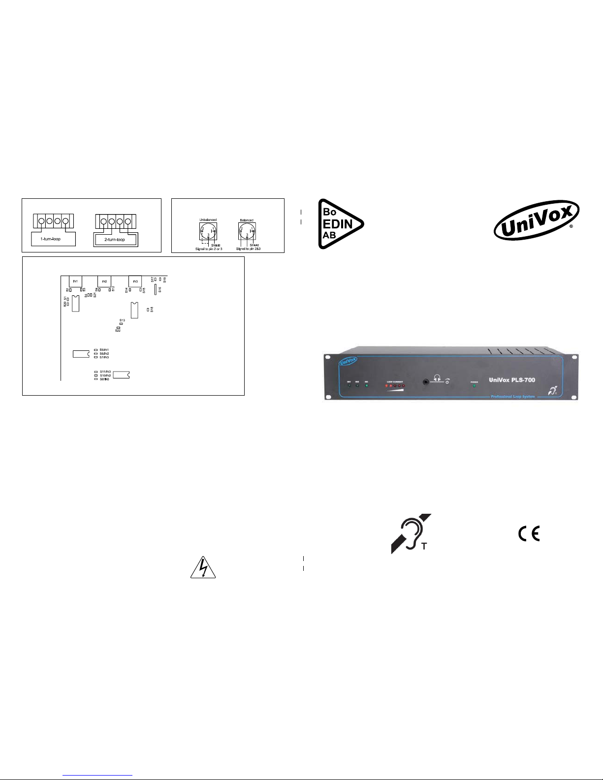
IN1:
S2&S3: open/closed = Phantom voltage pin 2&3 off/on. (Default=on)
S1&S20: open/closed = Microphone level/Line level. (Default=Microphone)
IN2:
S9&S12: open/closed = Phantom voltage pin 2&3 off/on. (Default=off)
S4&S21: open/closed = Microphone level/Line level. (Default=Line)
IN3:
S14&S15: open/closed = Phantom voltage pin 2&3 off/on. (Default=off)
S13&S22: open/closed = Microphone level/Line level. (Default=Line)
AGC:
S18: open/closed = AGC off/AGC on. (Default=AGC on)
Priority:
S8(IN1), S10(IN2) & S11(IN3): closed = The input overrides the other inputs. (Default S8=closed, S10&S11=open)
S5(IN1), S6(IN2) & S7(IN3): closed = The input will be overrided by the other inputs. (If the strap is open the input will
not be overrided independent of the settings of S8,S10&S11). (Default S7=closed, S5&S&=open)
IMPORTANT! Do NOT change the settings of S16, S17 & S19!
How to connect a 1-turn / 2-turn loop
How to connect unbalanced /
balanced input
Strap settings for Inputs 1-3 and for the AGC-function
WARNING!
Live terminals enclosed!
Page 2
UniVox® PLS-700 installation guide
General planning and installation procedures.
1.Preparations
a) If the loop cable is already planned, install according to the drawings. Then read clause 2.
b) if the loop cable is already planned and installed, read clause 2.
c) If the loop cable is to be planned and installed ”in situ”, please read the following hints.
Hints for planning the loop cable:
Use a 2x2.5mm² twin loop wire, this gives a high flexibility for the installer. If other loop wires are used, the amplifier’s efficiency may
be affected. Recommended minimum loop wire area is described in the table on page 3.
If the space for the loop cable is limited, a flat copper foil can be used as an alternative.
The field strength can be reduced due to reinforcement ironing and such like. If so, the field strength can be doubled (appr. 6dB) if 2
amplifiers are used, one for each separate wire of the twin wire, or use a more powerful amplifier as an alternative.
Do not place input cables close to / in parallel with the loop wire.
Do not place the loop wire close to reinforcement iron and such like.
If the smallest distance in a loop exceeds 10 meters, please consider another loop configuration, like the “eight”-loop.
Please be aware of the overspill effect. If the overspill is not acceptable, plan the system for UniVox
®
Super
Loop System with minimized overspill. Log on to
www.edin.se for more information.
Beware of the background noises created by other electrical equipment when planning the loop system.
Proceed to clause 2.
2. Installation.
Mount the amplifier in a 19”-rack. IMPORTANT! The amplifier must have free access to normal room temperature. If the
amplifier is to be mounted on a wall, the 6 rubber feet attached shall be mounted. The amplifier can be mounted
horissontally.
Connect the loop cable. Connect the
loop cable to terminal F on the rear
panel. Please look at page 4 for 1- or
2-turn loop connections.
Connect signal source/s to the inputs
”IN1-3”, K,L&M on the rear panel.
See page 4 for balanced/
unbalanced connections. The inputs
”IN1-3” can be set to different
sensitivities according to table. If you need to set IN1-3 otherwise than default, remove the cover and set the
switches S1-20 according to table at page 4. IMPORTANT! Disconnect the mains power before removing the cover.
Default settings:
IN1 = Microphone level, at input signal IN1 overrides IN3.
IN2 = Line level, no priority function.
IN3 = Line level, IN3 is overrided if input signal is present at IN1.
Input-AGC. The AGC-function for inputs IN1-3 can be disabled by setting the switch S18 according to table on page 4.
Connect Line Outputs:
UNIVOX® PLS-700 has 2 line outputs; I = ”LINE OUT” 0dBm without the input AGC activated (linear), and J
”SLS” 0dBm with the AGC-function activated.
Connect mains power to the inlet E. The LED D on the front panel starts lighting. UNIVOX® PLS-700 has an
automatic resettable built-in mains fuse. If it’s triggered by any reason, please remove the mains power and let
the amplifier cool off. Investigate the possible fault reason before reconnecting the mains power.
3. Function check (basic start up check)
Adjust the input levels one by one letting the LED A1-3 on the front panel emitting at the peaks of the program
signal source (AGC knee).
Increase the Loop Current trimmer G until the first LED B on the front panel lits up. Use the loop monitor output
C for direct listening to the output current (magnetic field). If necessary, adjust TREBLE with the potentiometer H.
4. Certification. Very important!
Adjust the amplifier following ”The UniVox Way” for certification according to IEC-60118-4 (BS6383) using a
field strength meter, like the FSM. The FSM follows the standard of Sound Meter with correct integration time
and true RMS measurement.
5. Inform people responsible for the loop system how to use the system. Recommend a listening device for a
daily basic check of the loop system. The UniEar is a high quality listening device with built-in level check.
Page 3
Page 2
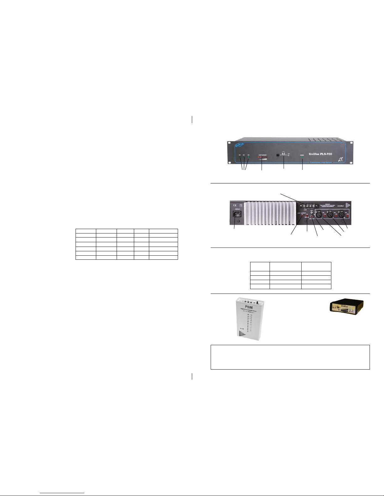
A1-3.
Input
check
B. Loop
check
D. Mains
power
indicator
C. Loop monitor,
6.3mm jack &
volume adjust.
E. Mains
connector
F. Loop cable
connector
G. Loop
current control
J. “SLS”
L. “IN 2”
K. “IN 3”
M. “IN 1”
Field Strength Meter FSM
Loop receiver UniEar
I. “LINE OUT”
H.Treble
UniVox PLS-700 Front panel
UniVox PLS-700 Rear panel
Sensitivity Impedance Priority
IN1 / Mic 0.5mV-100mV 7.8 kOhm IN1>IN3 Default setting
IN1 / Line 25mV-4V -”IN2 / Mic 0.5mV-100mV -”IN2 / Line 25mV-4V -”- Default setting
IN3 / Mic 0.5mV-100mV -”IN3 / Line 25mV-4V -”- IN3<IN1 Default setting
Loop area m² Wire area Wire area
1-turn-loop 2-turn-loop
300-650 >=5mm² Not recommended
150-300 >=4mm² 2x2.5mm²
70-150 Not recommended 2x2.5mm²
20-70 Not recommended 2x2.5mm²
Recommended minimum loop wire area for UNIVOX® PLS-700
when installed to an existing loop system.
Distributor:
 Loading...