

Page 1
User Guide
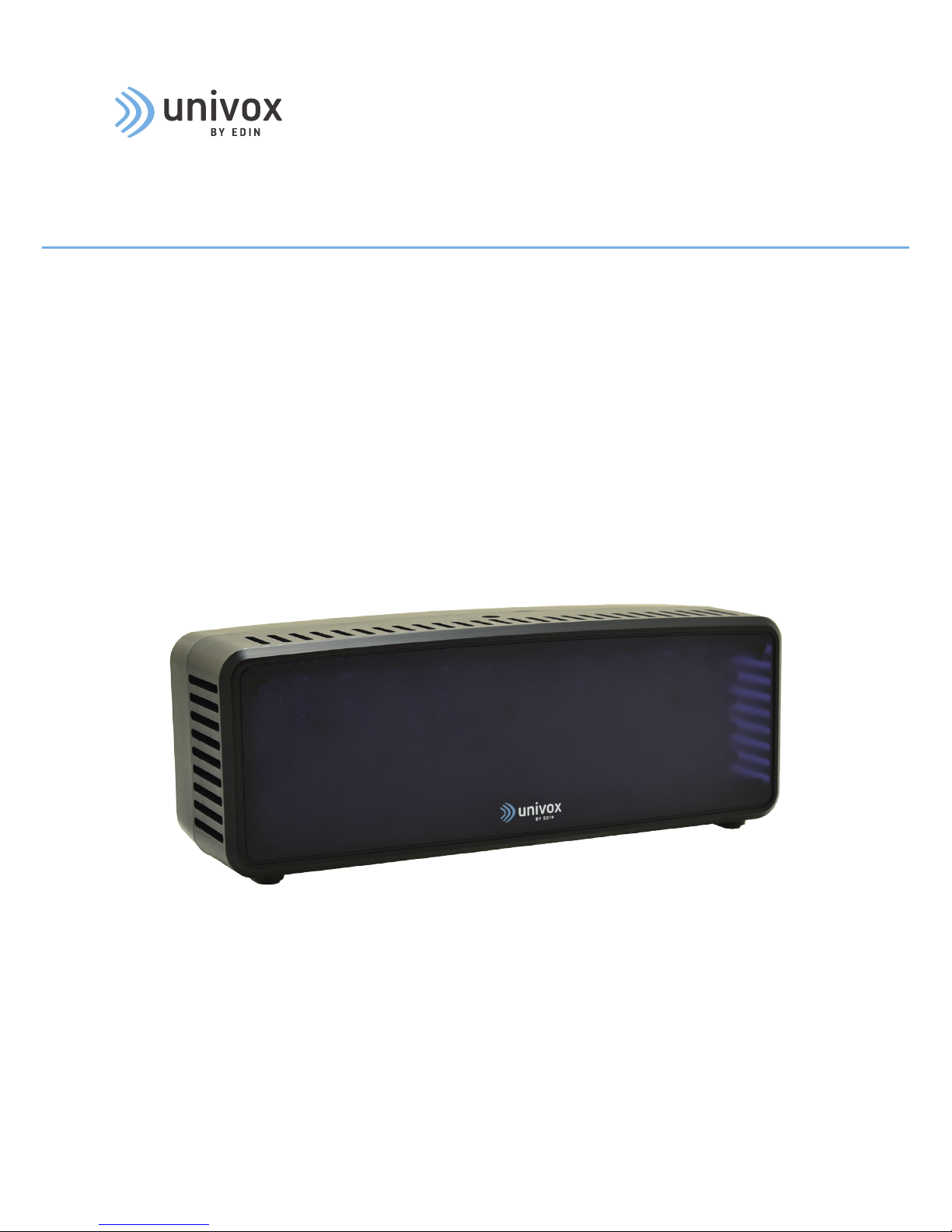
Univox® IR 1411
Infrared Transmitter
Part no. 650300
Page 2

2
Introduction
Thank you for choosing a Univox® product. We hope you will be satisfied!
Univox® IR 1411 is a compact, yet powerful IR transmitter for small to medium size venues.
The sleek low-profile design is ideal for installation in boardrooms, houses of worship,
cinema/theatres, courtrooms, nursing homes, auditoriums and class rooms etc.
Univox®IR 1411 works in conjunction with Univox® IRR-1 receivers. The powerful infrared
transmitter features all-in-one modulator and 72-diodes emitter for high performance and
large coverage – up to 600m
2
with a single unit.
Univox®IR 1411 provides wireless assistive listening with supreme audio quality. With
single mono- or dual channel stereo operation on 2,3 and 2,8 MHz carrier frequencies,
the unit is ideal for applications where information security and overspill control are of
importance.
Please read this user guide carefully before installation and use of this product.
Included in the package
• Univox® IR 1411 transmitter
• Power supply unit
• Wall/ceiling mounting kit
• Twin 3.5mm mono to stereo cable
• Phoenix screw terminal
Contents
Introduction ............................................................................................................................................... 2
Features and settings ..............................................................................................................................3
Placement .................................................................................................................................................. 5
Operating Instructions ............................................................................................................................. 5
Troubleshooting ........................................................................................................................................6
Maintenance .............................................................................................................................................. 7
Warranty ..................................................................................................................................................... 7
Safety .......................................................................................................................................................... 7
Environment .............................................................................................................................................. 7
Technical data .......................................................................................................................................... 8
Page 3
3
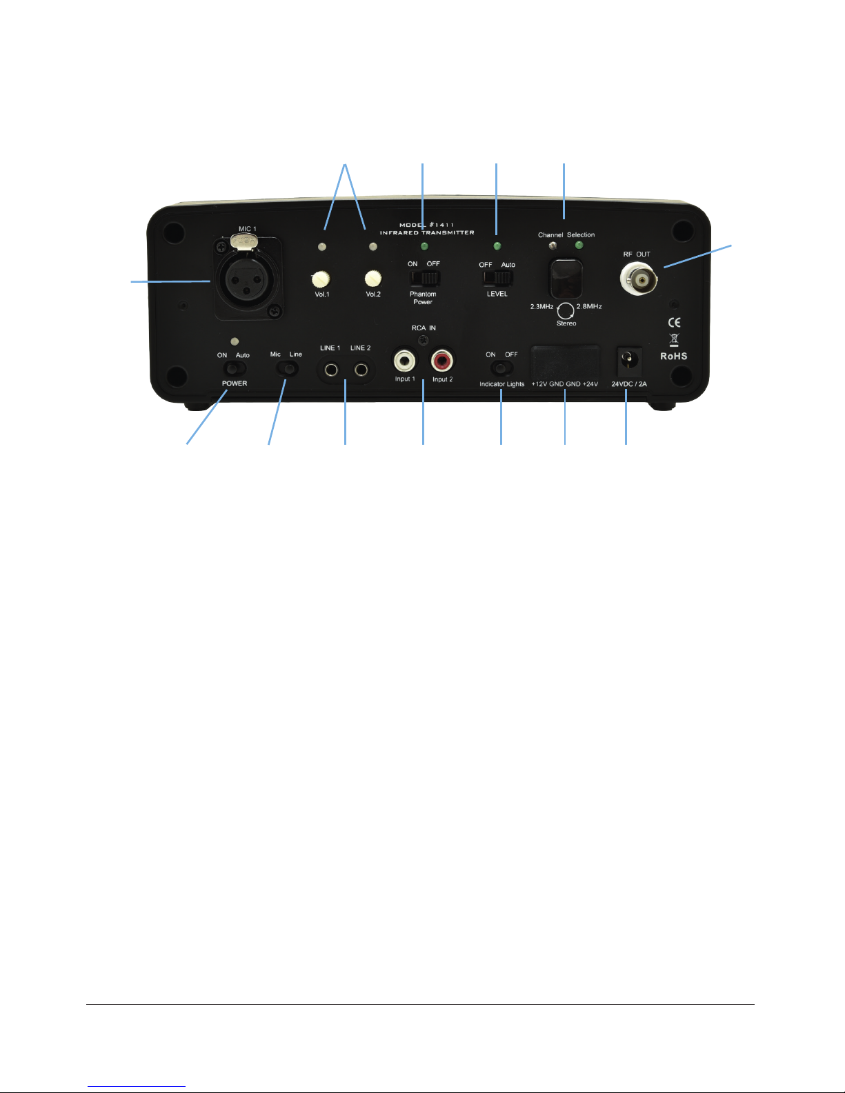
Features and settings
1
13 12 11 10
9
8765432
Details
1. XLR – Balanced Mic or Line* input
*Optional adapter is available at request for balanced line, 0dBu level sensitivity.
2. Power Save-mode switch
”ON” – unit is transmitting with or without input signal. LED indicates red.
“Auto” – Power save mode activated – transmitting only if input signal is present. LED
indicates amber.
3. Mic/Line switch
Select between XLR
(1) or 3.5 mm/RCA (4, 5) inputs:
Mic – balanced XLR Mic or Line*
(1) level input with 12 V Phantom voltage (12).
Line – unbalanced RCA or 3.5 mm line level inputs, mono or stereo.
1. XLR – Balanced Mic or Line input
2. Power Save-mode switch
3. Mic/Line switch
4. 3.5 mm – Line 1 & 2 – Unbalanced line input
5. RCA – Line 1 & 2 – Unbalanced line input
6. Indicator Lights switch – ”ON/OFF”
7. Header DC input/output
8. DC power supply input – 24VDC
9. RF Out – BNC jack
10. Channel/Frequency Selection toggle switch
11. Automatic Level Control (ALC) switch – ”OFF/Auto”
12. Phantom Power (12V) switch – ”ON/OFF”
13. Volume controls
Page 4

4
4-5. 3,5 mm/RCA – LINE/Input 1 & 2 – Unbalanced line inputs
LINE 1/Input 1 – Controlled by Vol 1 volume control
LINE 2/Input 2 – Controlled by Vol 2 volume control
Note: With Auto Level activated the Volume level controls are disabled.
6. Indicator Lights switch – ”ON/OFF”
7. Header DC input/output
24 VDC – Connection of external 24VDC supply voltage. Note: AC adapter is not
connected.
12 VDC – Power supply to external emitter panel
8. DC power supply input
Note: Univox supplied power adapter only.
9. RF Out – BNC jack
Modulated HF signal output to expansion units or additional emitter panels.
10. Channel/Frequency Selection toggle switch
Select the transmission frequency by pressing the button repeatedly.
2.3 MHz – Le LED indicates amber
2.8 MHz – Right LED indicates green
Stereo transmission, 2.3 MHz Le and 2.8 MHz right – both LEDs, amber and green
indicates
11. Automatic Level Control (ALC) switch – ”OFF/Auto”
“OFF” – ALC disabled - LED off. Use level volume controls
(13) to adjust the input
level. “Auto” – ALC enabled - LED indicates green. The unit is equipped with automatic
adjustment of the audio level – recommended setting.
12. Phantom Power (12V) switch – ”ON/OFF”
Green LED = ON
13. Volume controls
Input level adjustment if Automatic level control
(11) is disabled.
Volume 1 – XLR or Line/Input No.1
Volume 2 – Line/Input No.2
Indicator LED’s for each input:
Green – nominal audio signal strength
Amber – approaching audio signal clipping. Indicators light up when the
input signal level is 6dB below clipping.
Red – audio signal clipping input, approaching distortion. Adjust the
input level so LED flickers red occasionally, indicating audio peaks.
Page 5

5
Placement
The unit is supplied with a universal mounting kit allowing for easy and quick installation.
Select an appropriate mounting location, considering the shape and size of the room,
to ensure optimal coverage. Recommended placement for best performance is above
2 m height, slightly angled (10-30 degrees) toward listening audience. Make sure the
transmitter has direct line-of-sight to the audience.
Operating Instructions
1. Connect the primary audio source to a suitable input:
- Balanced: XLR Input (1).
- Unbalanced: 3.5mm - Line 1 and 2 (4) or RCA – Input 1 and 2 (5)
Set Mic/Line switch (3) accordingly.
2. Connect the supplied power adapter to the DC supply input
(8) and set Power switch to
“ON”. The red LED indicates power connection.
3. Set Audio Level Control (ALC) switch
(11) to “Auto” – green LED is lit. Input level will be
adjusted automatically - recommended setting.
Note: Setting the switch in “OFF” position will disable ALC – green LED is off. Audio level
for each input must be adjusted manually by Volume controls Vol 1 and 2 (13). Adjust
the input level so both LEDs flicker red occasionally, indicating audio peaks.
4. Set the carrier frequency by pressing the Channel Selection Switch
(10) repeatedly.
Recommended setting for assistive listening mode is Stereo (2.3 and 2.8 MHz
transmission) – both amber and green LED indicates.
Note: Make sure both transmitter and receiver are set to the same channel frequency.
Page 6

6
Troubleshooting
Transmitter has no power
• Verify that the power supply is connected properly, (red/amber LED on the transmitter
should be lit, depending on the mode selected).
• Check the power adapter function, (green LED=ON). Replace if faulty.
No audio or poor audio quality (distortion)
• Check the input signal connection.
• Verify that the Mic/Line switch setting is in accordance with signal level and input
connected.
• Check the Audio Level Control (ALC) switch setting, (green LED=ON). If disabled, (ALC
switch=OFF), the input level should be adjusted by Vol1 and Vol2 level controls.
• Check and adjust the audio level, if necessery. The Volume Control LEDs are indicating
red occasionally if the unit is transmitting correctly.
• Make sure the transmitter and receiver are operating at the same channel/frequency,
(for best performance Stereo setting is highly recommended). Verify that both amber
and green LED at the transmitter are lit, and receivers channel switch is set in S-mode
(Stereo).
• Make sure the receivers are in the line-of-sight and range of the transmitter and the
IR-light is not blocked in any way.
Audio Level indicators are not lit
• Make sure the Indicator Light switch is in “ON” position
• Verify that the audio input is connected properly.
• Check that the Mic/Line switch setting in accordance with signal level and input
connected.
The Installation Guide is based on the information available at the time of printing and are
subject to change without notice.
Page 7

7
Maintenance
Under normal circumstances the product does not need any special maintenance.
Should the unit become dirty, wipe it with a clean damp cloth. Do not use solvent or strong
detergents.
Warranty
Product is covered by 2 years warranty.
The equipment should be installed following the instructions contained within this
document. The product warranty doesn't cover failure caused by tampering, carelessness,
improper handling or maintenance.
Use only the power adapter supplied with the unit.
Service
In case of failure, if the product should not work properly aer the troubleshooting has
been performed, please contact your local distributor for further instructions.
Refer all servicing to qualified service personnel only. If the product is sent to Bo Edin AB,
please enclose a filled Service Form, www.univox.eu/support.
Safety
The installer is responsible for installing the product in a way that may not cause
risk of fire, electrical malfunctions or danger for the user. Do not cover the unit or
the power adapter. Only operate the unit in a well ventilated, dry environment.
Do not remove any covers as there is a risk of electric shock. Please observe that the
product warranty doesn’t include faults caused by tampering the product, carelessness,
incorrect connection/mounting or maintenance.
Bo Edin AB shall not be held responsible or liable for interference to radio or TV equipment,
and/or to any direct, incidental or consequential damages or losses to any person or
entity, if the equipment has been installed by unqualified personnel and/or if installation
instructions stated in the product Installation Guide have not been strictly followed.
Environment
To prevent possible harm to the environment and human health, please dispose of
the product responsibly by following statutory disposal regulations.
Page 8

Hearing excellence since 1965
(Univox) Bo Edin AB
Stockby Hantverksby 3,
SE-181 75 Lidingö, Sweden
+46 (0)8 767 18 18
info@edin.se
www.univox.eu
ir-1411-du-gb 190114 Copyright © Bo Edin AB
Technical data
Univox® IR 1411 Transmitter part no 650300
Modulation FM, + 35kHz nominal + 50kHz peak
IR Light Wavelength 870nm
Carrier Frequency 2.3MHz, 2.8MHz
or Stereo: 2.3MHz (Le) and 2.8MHz (Right)
Pre-emphasis 50µS
Audio Frequency response 50Hz - 18kHz (±1 dB)
Total Harmonic Distortion < 1%
Signal-to-noise Ratio 75dB
Input 1 (MIC 1) Balanced XLR
Impedance: >50Ω / >2kΩ
Phantom Power: Approx. 12VDC
Maximum input level: 20dBm (7.75V)
Input 2 (Line 1/Line 2) Unbalanced Line, Stereo Input. Two 3.5mm connectors
Input 3 (RCA IN) Unbalanced Line, Stereo Input. Two (RCA) Phono connectors
Input: -10dBu Nominal +14dB headroom
Impedance: 10kΩ
Indicators Green LED: nominal range of audio level
Red LED: audio peak indicator, approaching audio distortion
Output connection BNC x 1
RF Output Voltage Approx. 750 mVrms (2Vpp)
Output Impedance Approx. 50kΩ
IR LEDs 72 diodes
Radiating Power Approx. 2W
Coverage Up to approx. 600m
2
(64582)
Supply Voltage 19VDC min - 28VDC max
Power Supply Input 100-240VAC 50/60Hz
Power Supply Output 24VDC @ 2A
Power Connection 2.5mm DC jack (or 4-Pin Phoenix connector)
Weight 450g (1lb); Power Supply: 360g (0.8lb)
Dimensions (W) 210 x (D) 70 x (H) 80mm (8.3” x 2.8” x 3.1”)
Color Black
 Loading...