

Page 1
User Guide
Univox® FSM Basic
AFILS Field Strength Meter
Part no 401014
Page 2

2
Content
Introduction ������������������������������������������������������������������������������������������� 2
Overview ������������������������������������������������������������������������������������������������� 3
Background information ��������������������������������������������������������������������� 3
Instructions for use ������������������������������������������������������������������������������ 4
Field strength deviation/overspill (Coverage) �������������������������������� 4
Basic frequency test (FQ) ������������������������������������������������������������������� 5
Adjustment of field strength level (Field) ��������������������������������������� 6
System commissioning ����������������������������������������������������������������������� 6
Safety, Care and Maintenance ����������������������������������������������������������� 7
Calibration ���������������������������������������������������������������������������������������������� 7
Batteries ������������������������������������������������������������������������������������������������� 7
Specification ������������������������������������������������������������������������������������������ 8
Environment ������������������������������������������������������������������������������������������ 8
Introduction
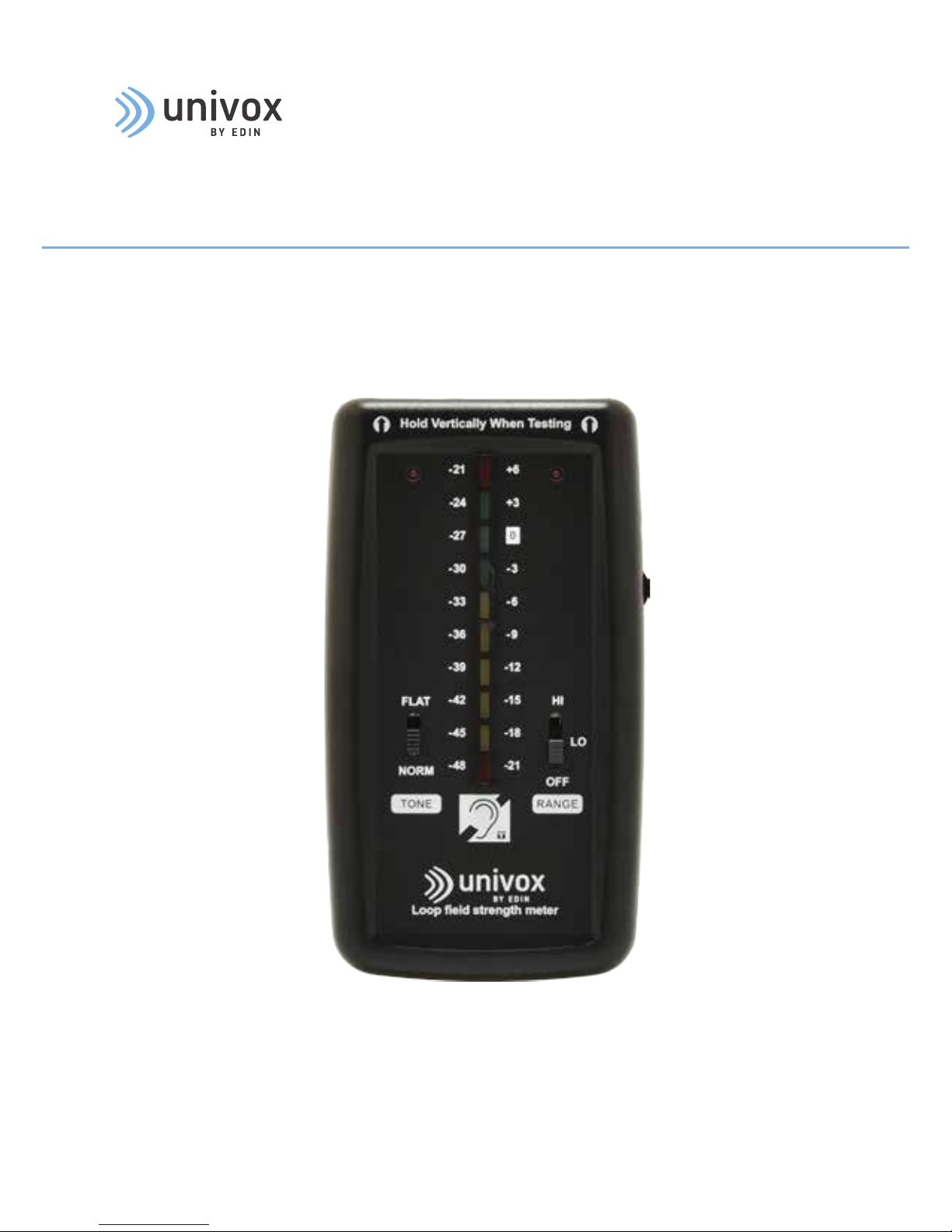
Univox® FSM Basic is a calibrated precision measurement device, designed for measuring
the performance of Audio Frequency Induction Loop Systems (AFILS)� The meter enables
easy and straight-forward assessment of background noise, field strength and frequency
response of the system to comply with the requirements of IEC 60118-4�
Two different frequency response characteristics are provided: 'NORMAL' which is
a restricted response, similar to that of a hearing aid, and 'FLAT' which is a wide,
flat response, similar to that of an equalized induction loop receiver for wide-band
communication�
The meter is calibrated in two ranges; +6dB to -21dB and -21 to -48dB with respect to the
field strength of 400mA/m, recommended by IEC 60118-4, allowing background magnetic
noise levels to be measured as well as AFILS signal strengths� The measured audio signal
may be monitored using headphones on all range and filter combinations�
Page 3
3
Background information
• The meter responds to program peaks� The PPM style of indicator was developed by
broadcasters to control the peak levels of audio signals and so prevent overmodulation
of the transmitters� The PPM meter allows the user to verify in real time that an AFILS
can provide sufficient field strength for good speech clarity�
• The monitor audio output is active on all range and filter combinations� The monitor
output frequency response is modified to emulate that of a typical induction loop
listener� This means that the person testing hears a similar signal to that to be heard by
a loop user�
• The meter is operated in the vertical plane so that is easy to read when held at the
hearing position�
• This meter is designed with high quality components for low noise and operates over a
very wide range of 54dB in two stages� The range in use is indicated by an LED as is a
low battery condition warning�
• Two measurement filter (tone) responses are provided� The FLAT setting is provided
only for measuring system frequency response in conjunction with an external signal
generator� For all other measurement the NORMAL setting is used�
• The meter is calibrated, traceable to International Standards� Annual checking of
calibration is advised�
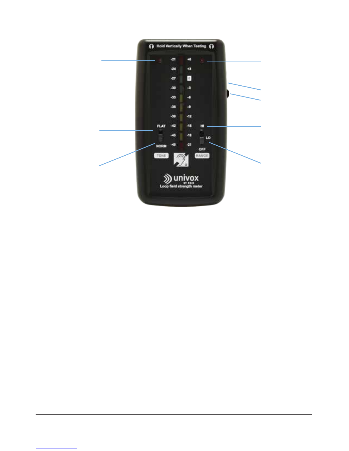
Overview
1� LO range when lit*
2� HI range when lit*
3� 0dB=400mA/m
4� Headphone socket
5� Volume control
7� HI range for AFILS
signal strength
9� LO range for
background
magnetic noise
6� FLAT - AFILS
frequency response only
8� NORM - AFILS for
hearing aids
* The range indicator in use flashes when the battery is low�
Page 4

4
Instructions for use
Background noise measurement (Noise)
NOTE: Do not use the monitor headphones on higher than volume 4 for this test, (i�e� on LO
range setting) in order to maintain accuracy and stability in the instrument�
1� Switch off or disconnect from the mains power any audio induction loop equipment,
(note that any other mains operated equipment, that normally would be in use within
the test area, should be switched on)�
2� Set the TONE (filter) switch to the NORM position (8)�
3� Move the RANGE switch to the LO position (9)�
4� Hold the meter in vertical position, with the top at the position a hearing aid is likely to
be used, (1�2m for sitting and/or 1�7m for standing height� If both sitting and standing
positions are used, measure at 1�45m)�
5� Observe the LED bar graph and document the background noise levels within the
listening area�
NOTE: For long time listening the IEC 60118-4 recommended background noise level
should be below -47dB� If the background noise level exceeds -32dB, the nature of the
magnetic noise should be assessed and remedial measures to achieve lower background
noise level should be considered� For short time announcements, background noise levels
of up to -22dB can be accepted, as the loop system will still be beneficial to hearing aid
user�
Field strength deviation/overspill (Coverage)
NOTE: For Field strength deviation/overspill (Coverage) measurement a precise 1kHz
frequency signal, Univox 1kHzSineWave�mp3 should be used�
1� Connect the loop driver to the mains power�
2� Connect the signal source and activate the audio file 1kHzSineWave�mp3�
3� Adjust the input level at the loop driver according to the manual�
4� Adjust the field strength level at a reference measuring position to approximately
-12dB�
5� Set the TONE (filter) switch to the NORM position (8)�
Page 5

5
6� Move the RANGE switch to HI position (7)�
7� Hold the meter in vertical position with the top at the listening height and measure
the variation (field strength deviation) within the listening area� Confirm that the field
strength does not deviate by more than ±3dB�
8� Measure the overspill distribution outside the loop area, if required� (NOTE: overspill is
not defined by the IEC 60118-4 but can be considered as magnetic field above -32dB�)
Basic frequency test (FQ)
NOTE 1: For Frequency test Univox MultiFreq�mp3 (the audio file includes 3 tones in the
following sequence: 2sec@1kHz; 1sec@silence, 2sec@100Hz; 2sec@5kHz), should be
used�
1� Activate the audio file MultiFreq�mp3�
2� The loop driver input level should be set according to the manual and the field strength
level adjusted to -12dB� Make sure that the output does NOT saturate, or clip�
3� Set the TONE (filter) switch to the FLAT position (6)�
4� The RANGE switch should be set to HI position (7)�
5� Hold the meter in a vertical position with the top at the listening height and measure
the frequency response for 100kHz, 1kHz and 5kHz� The frequency response for
100Hz to 5kHz should be within the range ±3dB with reference to the response at
1kHz� If the deviation is larger, try to adjust the frequency response with the drivers
MLC control, (refer to the driver´s manual)�
6� Aer any frequency adjustment(s), double-check that the loop driver delivers 400
mA/m (0dB) in program peaks, without clipping�
NOTE 2: It is not uncommon for certain locations within the area of a loop system to suffer
poor background noise, frequency response or signal strength, due to the surrounding
construction metal and layout of electrical services in a building� If the majority of the area
covered by the loop gives satisfactory signal to noise ratio then the poor areas may be
marked as not suitable for hearing aid users, as recommended by IEC 60118-4�
Page 6

6
Adjustment of field strength level (Field)
NOTE: Univox 1kHz_pulse�wav or itu�wav test signal should be used for adjustment of field
strength level� A continuous sine wave is not recommended since the loop driver’s AGC
might decrease the level�
1� Activate the audio file 1kHz_pulse�wav�
2� Adjust the input level according to the driver’s manual�
3� Set the TONE (filter) switch to the NORM position (8)�
4� Set the RANGE switch to HI position (7)�
5� Hold the meter in a vertical position and adjust the field strength level until
0dB (400mA/m) at the listening height is achieved� (A representative reference
measurement position is midway between the center of the loop and the loop
perimeter�)
6� Confirm that the field strength level does not vary more than ±3dB within the listening
area�
System commissioning
1� Connect the actual signal source/s, preferably speech, and adjust the input level
according the loop driver’s manual, (if the primary sound source is unavailable,
haspeech�wav or itu�wav audio files can be used)�
2� Set the TONE (filter) switch to the NORM position (8)�
3� Set the RANGE switch to HI position (7)�
4� Hold the meter in a vertical position at the listening height�
5� Measure the field strength and verify that the highest peak reaches 0dB (400mA/m) by
observing the highest reading� Confirm that the field strength variation within the room
is within ±3dB�
6� Check that the sound quality (clear sound with no distortion) is acceptable by listening
to the sound of the loop through the monitor headphones at a comfortable volume�
Page 7

7
Safety, Care and Maintenance
Keep the unit away from heat sources such as radiators, heaters, or other appliances that
produce heat�
Do not expose the unit to direct sunlight�
Do not use the unit near water�
Avoid objects or liquids getting into or onto the unit�
Clean only with a damp cloth� Do not use abrasive cleaners�
Do not remove screws from or open the unit casing� This will invalidate the calibration and
any warranty�
Damage to hearing can occur with consistent exposure to high volume when using
headphones� Always check the volume level before using headphones�
Calibration
The unit is calibrated in three points, (-12dB, -6dB, and 0dB) to meet IEC6 60118-4
requirements� If measurement accuracy is critical the instrument should be recalibrated
annually� Have the calibration rechecked if the instrument is dropped or otherwise
damaged�
Batteries
Press and slide battery cover to remove�
Orientate the battery as shown in the battery compartment molding� No harm will occur if
the battery is reversed but the instrument will not work�
Rechargeable batteries are not recommended for infrequently used equipment due to
self-discharge but can be used in the instrument� Operating life will be shorter from a
rechargeable battery than from the alkaline battery�
Replace the battery as soon as convenient aer the red range indicator(s) start to flash�
Switch off the meter when not in use to prolong the working life of the battery�
Remove the battery if not required for an extended period of time and remove an
exhausted battery as soon as possible to prevent leakage�
Dispose of the old battery according to the local regulations�
Page 8

Hearing excellence since 1965
(Univox) Bo Edin AB
Stockby Hantverksby 3,
SE-181 75 Lidingö, Sweden
+46 (0)8 767 18 18
info@edin.se
www.univox.eu
univox-fsm-basic-du-gb 180522 Copyright © Bo Edin AB
Specification
Power: 1 x PP3 9V alkaline
Current drain: 20-50mA
Battery life: >10 hours
Indicating ranges: -51dB to -24dB and -24dB to +3dB with respect to 0�40A/m
Indicator style: BBC/EBU Peak Program Meter (3ms attack, 650ms decay)
Resolution: 3dB
Absolute accuracy: ±0�5dB@0dB (400mA/m) and -27dB(18mA/m)
reducing to ±1�5dB@-24dB(25mA/m) and -48dB(1�6mA/m)
Filter characteristics NORM: -3dB@630Hz & 5kHz
FLAT: -3dB@40Hz & 14Hz
Headphone monitor: Max 2x19mW into 32ohms
Relevant standards: EN 60118-4
Environment
Please follow existing disposal regulations in your country� If you respect these
instructions you ensure human health and environmental protection�
 Loading...