

Page 1
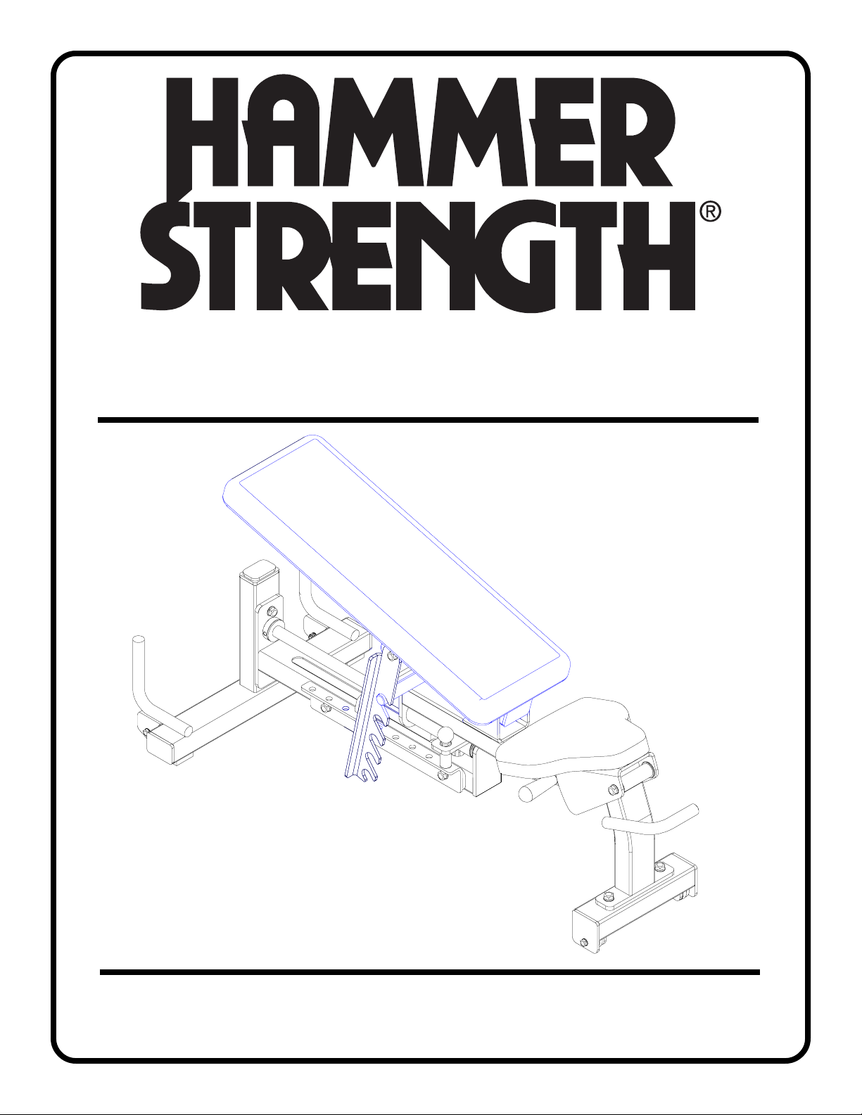
OLYMPIC HEAVY DUTY
ADJUSTABLE BENCH (OHDADJ)
Part # 7627001
Rev. A
ASSEMBLY INSTRUCTIONS
Revision:12/18/031
Page 2
PARTS LIST
KEY
1
2
3
4
5
6
7
8
9
10
11
12
13
14
15
PART #
LEA7595201
LEA7603101
LEA7605301
LEA7605401
LEA7603401
LEA7605501
LEA7603901
LEA7604401
LEA7604801
LEA73519XX
LEA73540XX
LEA7605701
LEA7656301
LEA3238304
LEA3247904
DESCRIPTION
UPPER BENCH FRAME
BACK PAD SUPPORT
ADJUSTABLE SEAT SUPPORT
GUIDE ROD
LOWER BENCH FRAME
BENCH ADJUST ANGLE
REAR BENCH SUPPORT
FRONT BENCH SUPPORT
BACK PAD ADJUST
SEAT PAD
BACK PAD
SPRING PIN ASSEMBLY
2” OD WHEEL
M10 X 35mm FLAT HEAD BOLT
M10 X 35mm BOLT
QTY
1
1
1
1
1
1
1
1
1
1
1
1
4
2
4
KEY
16
17
18
19
20
21
22
23
24
25
26
27
28
29
PART #
LEA3223305
LEA3233306
LEA3239304
LEA3239313
LEA3239318
LEA3239320
LEA3239340
LEA3239505
LEA3239503
LEA7617301
LEA3102801
LEA3102802
LEA7656201
LEA3242902
DESCRIPTION
3/8 X 2” BOLT
3/8 X 2-1/4” BOLT
1/2 X 1” BOLT
1/2 X 3-1/4” BOLT
1/2 X 4-1/2” BOLT
1/2 X 5” BOLT
1/2 X 10” BOLT
1/2” INT TOOTH LOCK WASHER
3/8” INT TOOTH LOCK WASHER
1/2” PLASTIC DOME WASHER
1/2” LOCK NUT
3/8” LOCK NUT
2” OD RUBBER WASHER
5/16 X 3/8” SET SCREW
QTY
2
2
2
4
1
1
1
12
12
4
7
4
2
2
Tools Required for Assembly
* 3/4”, 9/16, 17mm wrench
* Ratchet with 3/4”, 9/16” socket
* Metric Allen Wrench Set
Bolt Length Ruler
NOTE: BOLT LENGTH IS MEASURED FROM THE UNDERSIDE OF THE HEAD OF THE BOLT.
BOLT LENGTH
0
1/2 1/2 1/2 1/2 1/2 1/2
10 20 30 40 50 60 70 80 90 100 110 120 130 140 150
1
23456
2
Page 3
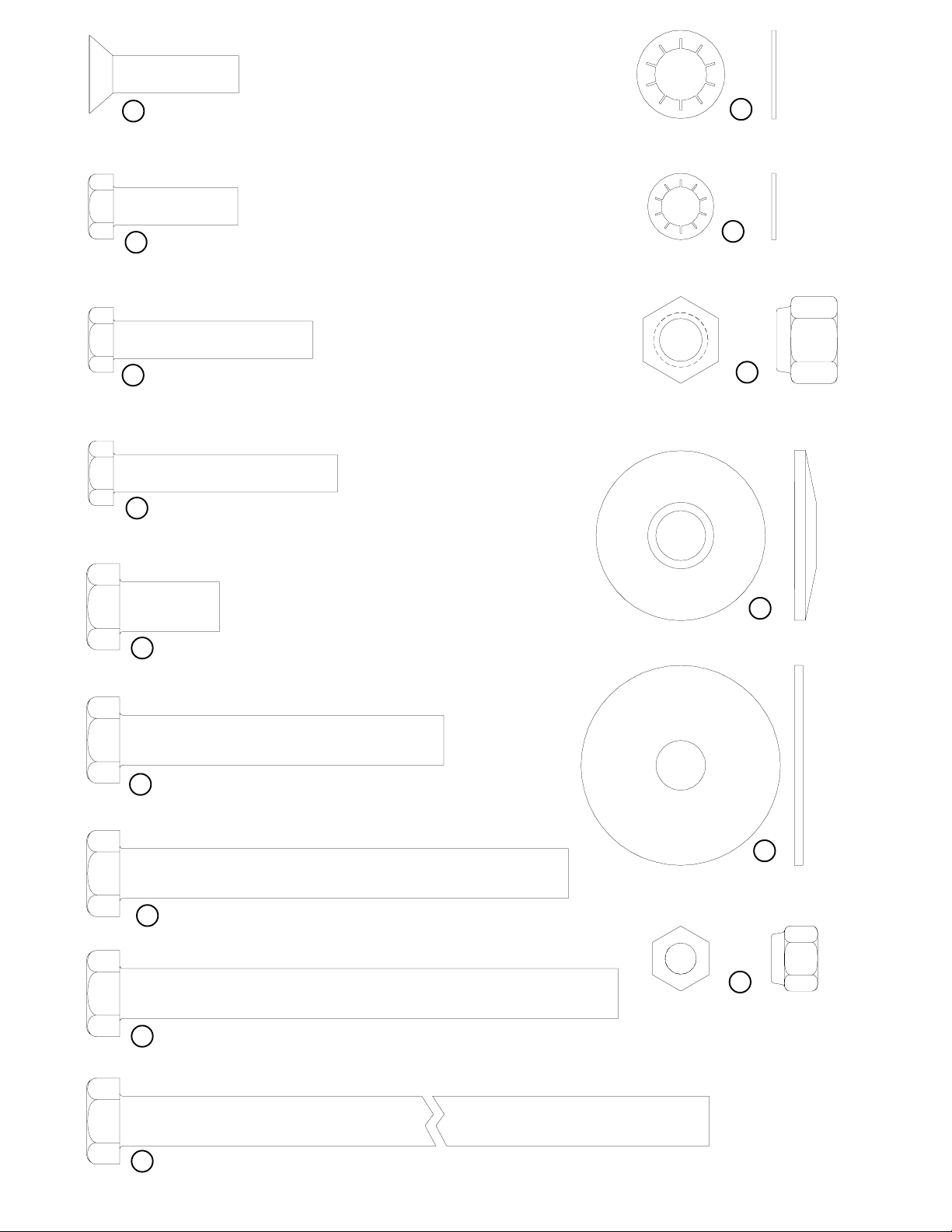
14 M10 X 35mm FLAT HEAD BOLT
23
1/2” INT TOOTH
LOCK WASHER
15 M10 X 35mm BOLT
16 3/8 X 2” BOLT
17 3/8 X 2-1/4” BOLT
18 1/2 X 1” BOLT
24
3/8” INT TOOTH
LOCK WASHER
26
1/2”
LOCK NUT
25
1/2” PLASTIC
DOME WASHER
19 1/2 X 3-1/4” BOLT
20 1/2 X 4-1/2” BOLT
21 1/2 X 5” BOLT
22 1/2 X 10” BOLT
28
2” OD
RUBBER WASHER
27
3/8”
LOCK NUT
3
Page 4
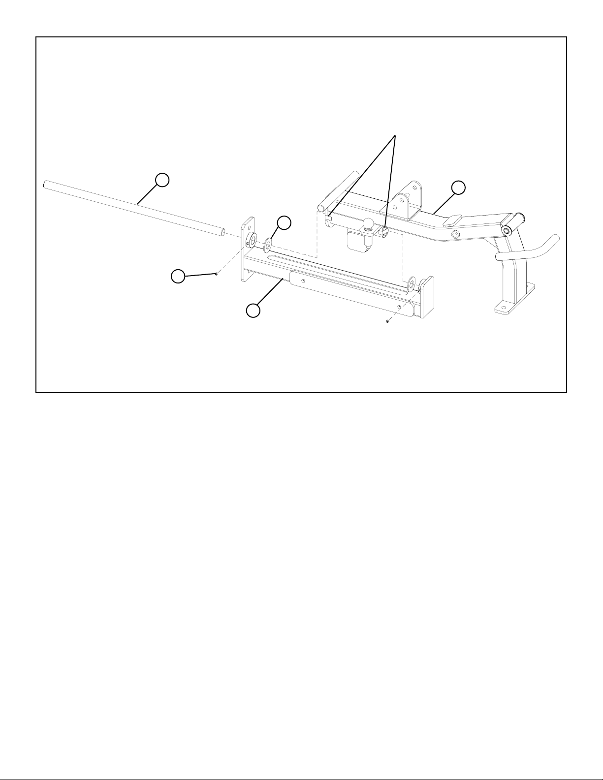
FIGURE 1
REMOVE TAPE FROM BOTH ENDS
OF THE HOUSING
4
28
29
5
1
STEP 1:
• Insert the GUIDE ROD (4) thru the SHAFT COLLAR and one 2” OD RUBBER WASHER (28) on the LOWER BENCH FRAME (5)as
shown in FIGURE 1.
• CAREFULLY slide the GUIDE ROD (4) through the HOUSING on the UPPER BENCH FRAME (1). (NOTE: Allow the GUIDE ROD (4)
to push the plastic tube out of the end of the HOUSING.) See FIGURE 1.
• Insert the GUIDE ROD (4) through one 2” OD RUBBER WASHER (28) and into the second SHAFT COLLAR on the LOWER BENCH
FRAME (5) as shown in FIGURE 1.
• SECURE the GUIDE ROD (4) to the SHAFT COLLARS on the LOWER BENCH FRAME (5) using two 5/16 X 3/8” SET SCREWS (29)
as shown in FIGURE 1.
• Push the 2” OD RUBBER WASHERS (28) up against both the SHAFT COLLARS on the LOWER BENCH FRAME (5) as shown in
FIGURE 1.
4
Page 5

FIGURE 2
7
27
13
24
3/8 X 2-1/4” 17
16 3/8 X 2”
8
STEP 2:
• SECURELY assemble two 2” OD WHEELS (13) to the REAR BENCH SUPPORT (7) using two 3/8 X 2” BOLTS (16), four 3/8” INT
TOOTH LOCK WASHERS (24) and two 3/8” LOCK NUTS (27) as shown in FIGURE 2. (NOTE: Do not over tighten this connection,
wheels should rotate smoothly.)
• SECURELY assemble two 2” OD WHEELS (13) to the FRONT BENCH SUPPORT (8) using two 3/8 X 2-1/4” BOLTS (17), four 3/8” INT
TOOTH LOCK (24) and two 3/8” LOCK NUTS (27) as shown in FIGURE 2. (NOTE: Do not over tighten this connection, wheels should
rotate smoothly.)
5
Page 6
FIGURE 3
26
25
7
23
19 1/2 X 3-1/4”
5
1/2 X 3-1/4” 19
1
8
STEP 3:
• SECURELY assemble the REAR BENCH SUPPORT (7) to the LOWER BENCH FRAME (5) using two 1/2 X 3-1/4” BOLTS (19), two
1/2” INT TOOTH LOCK WASHERS (23), two 1/2” PLASTIC DOME WASHERS (25) and two 1/2” LOCK NUTS (26) as shown in
FIGURE 3.
• SECURELY assemble the FRONT BENCH SUPPORT (8) to the UPPER BENCH FRAME (1) using two 1/2 X 3-1/4” BOLTS (19), two
1/2” INT TOOTH LOCK WASHERS (23), two 1/2” PLASTIC DOME WASHERS (25) and two 1/2” LOCK NUTS (26) as shown in
FIGURE 3.
6
Page 7
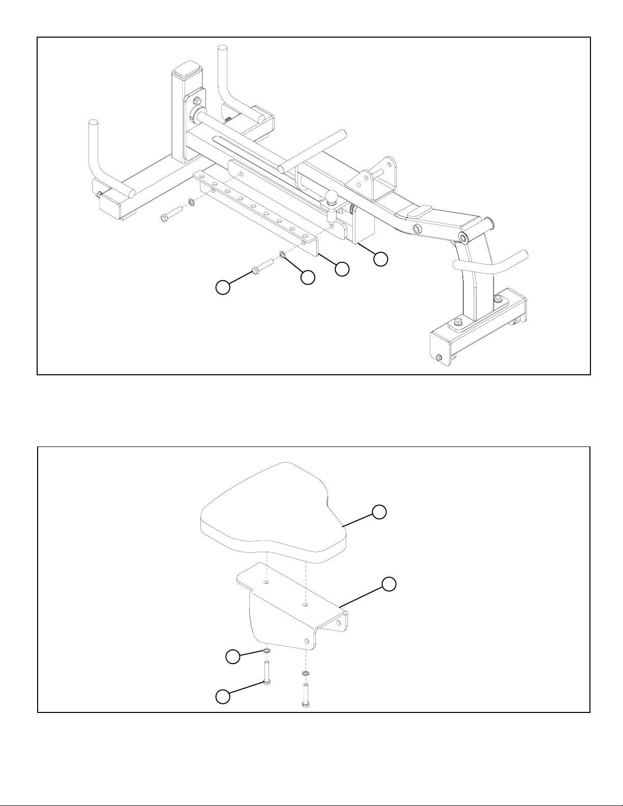
FIGURE 4
23
6
1/2 X 1” 18
5
STEP 4:
• SECURELY assemble the BENCH ADJUST ANGLE (6) to the LOWER BENCH FRAME (5) using two 1/2 X 1” BOLTS (18) and two
1/2” INT TOOTH LOCK WASHERS (23) as shown in FIGURE 4
FIGURE 5
10
3
24
M10 X 35mm 15
STEP 5:
• SECURELY assemble the SEAT PAD (10) to the ADJUSTABLE SEAT SUPORT (3) using two M10 X 35mm BOLTS (15) and two 3/8” INT
TOOTH LOCK WASHERS (24) as shown in FIGURE 5
7
Page 8

FIGURE 6
26
3
1
23
12
1/2 X 5” 21
STEP 6:
• SECURELY assemble the ADJUSTABLE SEAT SUPPORT (3) to the UPPER BENCH FRAME (1) using one 1/2 X 5” BOLT (21), two
1/2 INT TOOTH LOCK WASHERS (23), and one 1/2” LOCK NUT (26) as shown in FIGURE 6.
• Assemble one SPRING PIN ASSEMBLY (12) to the UPPER BENCH FRAME (1) as shown in FIGURE 6. (NOTE: Tighten jam nut
SECURELY.)
FIGURE 7
11
2
24
M10 X 35mm 15
M10 X 35mm 14
FLAT HEAD BOLT
STEP 7:
• SECURELY assemble the BACK PAD (11) the the BACK PAD SUPPORT (2) using two M10 X 35mm BOLTS (15), two M10 X 35mm
FLAT HEAD BOLTS (14) and two 3/8” INT TOOTH LOCK WASHERS (24) as shown in FIGURE 7
8
Page 9
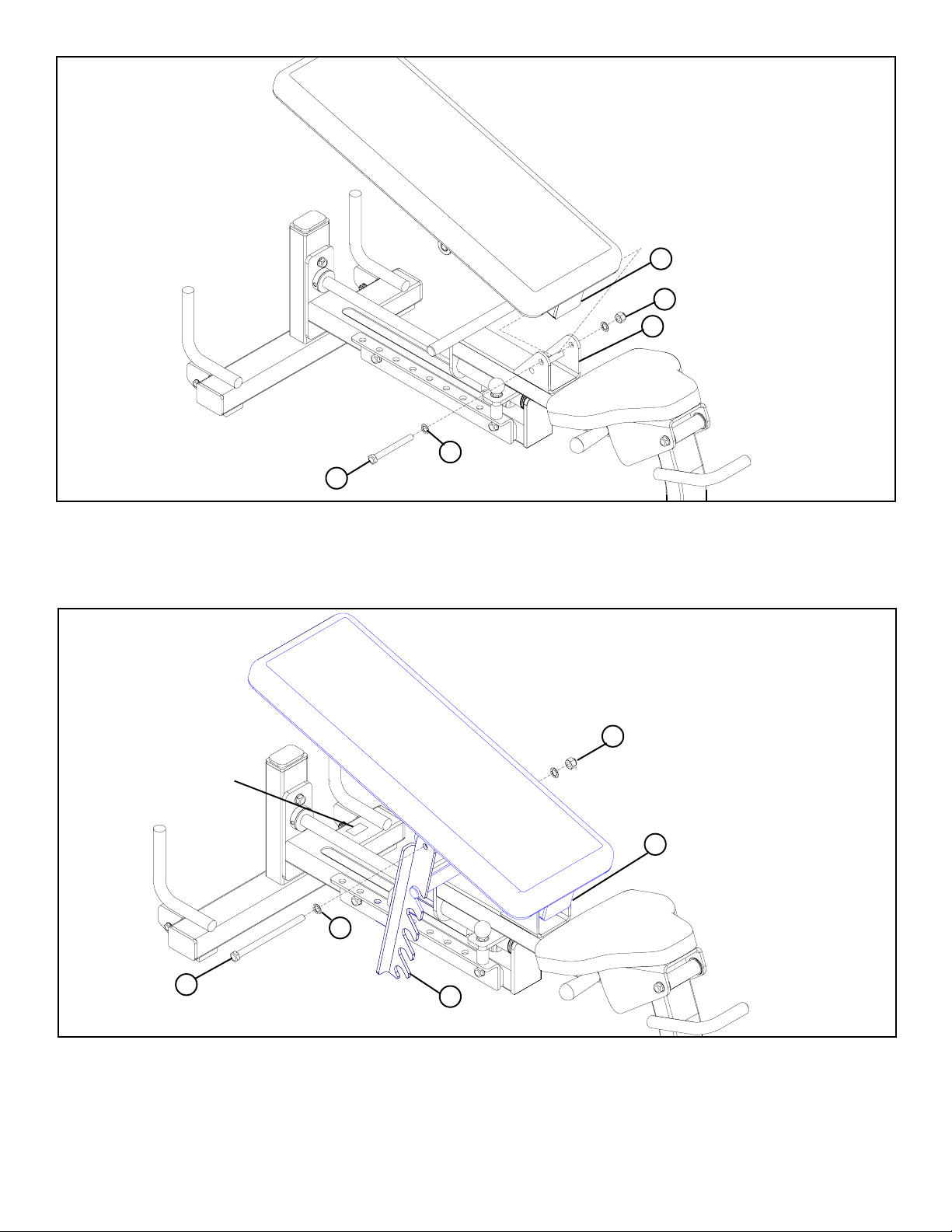
FIGURE 8
STEP 8:
2
26
1
23
1/2 X 4-1/2” 20
• SECURELY assemble the BACK PAD SUPPORT (2) to the UPPER BENCH FRAME (1) using one 1/2 X 4-1/2” BOLT (20), two 1/2 INT
TOOTH LOCK WASHERS (23) and one 1/2” LOCK NUT (26) as shown in FIGURE 8.
FIGURE 9
26
SERIAL NUMBER
2
23
1/2 X 10” 22
9
STEP 9:
• Assemble the BACK PAD ADJUST (9) to the BACK PAD SUPPORT (2) using one 1/2 X 10” BOLT (22), two 1/2 INT TOOTH LOCK
WASHERS (23) and one 1/2” LOCK NUT (26) as shown in FIGURE 9.
Thank you for purchasing the OLYMPIC HEAVY DUTY ADJUSTABLE BENCH. If unsure of proper
use of equipment, call your local Hammer Strength distributor .
9
Page 10

CAUTION-PLEASE READ
There is a risk assumed by individuals who use this type of equipment. To minimize risk, please
follow these rules:
1. Inspect equipment daily. Tighten all loose connections and replace worn parts immediately.
Failure to do so may result in serious injury.
2. Do not allow minors or children to play on or around this equipment.
3. Exercise with care to avoid injury.
4. Consult your physician before beginning any exercise program.
WARRANTY INFORMATION
10 YEARS
Structural Frame
(Not Coatings)
Pillow Blocks, Pulleys,
Weight Plates, and Guide Rods
CONTACT INFORMATION
United States, Canada,
Latin America
800.634.8637
847.288.3399
Europe, Africa, Middle East
VISIT US AT: HAMMERSTRENGTH.COM
PREVENTATIVE MAINTENANCE TIPS
Action DAILY WEEKLY QUARTERLY BI-ANNUALLY AS NEEDED
CLEAN
Upholstery
Guide Rods
Hand Grips
INSPECT
Visual Overall
Cables
Hardware
Frame
Hand Grips
LUBRICATE
Guide Rods
5 YEARS
(+31) 180.646666
X
X
X
Belts and Grips
(+852)2891.6677
X
1 YEAR
Asia Pacific
90 DAYS
Upholstery and Any Items
Not Specified
United Kingdom
+44(0)1353.666017
X
X
X
X
X
Clean:
• Upholstery with mild soap and water.
• Guide rods with a cotton cloth.
• Hand grips with mild soap and water.
• Frame damage can be repaired with touch-up paint can be purchased from your Hammer Strength customer service representative.
Inspect:
• Cables for wear or damage and proper tension (should not exceed 3/4” deflection.) Pay close attention at bends and attachment
points.
• Hardware should be checked for looseness. Tighten as required.
• Frames should be inspected for wear or damage.
• Hand Grips should be checked for wear or damage
Lubricate:
• Lube the Guide Rods. Apply the lubricant to a cotton cloth, then run the cotton cloth up and down the guide rods as needed. Do not
spray lubricant directly on the Guide Rods.
10
 Loading...