

Page 1
OPERATORS
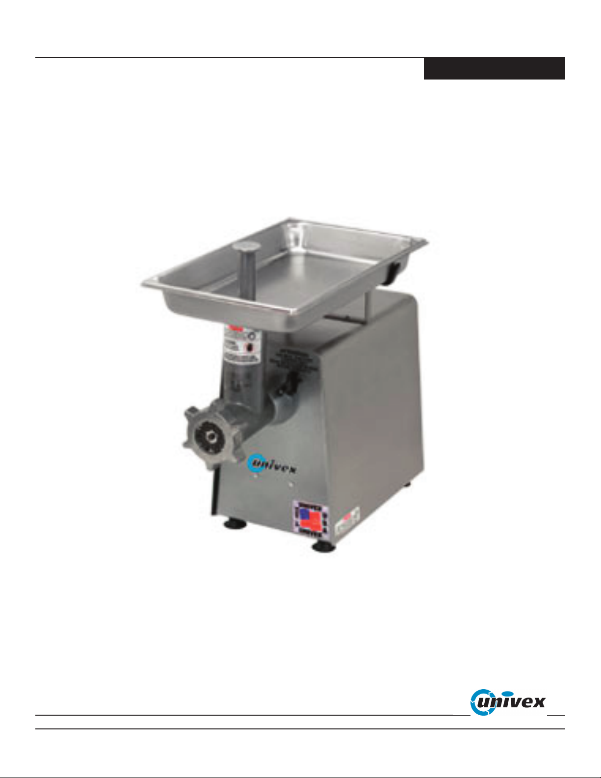
MG8912
MANUAL
MEAT GRINDER
MG8912/0109 ED 1
0018912
Page 2

TABLE OF CONTENTS
DESCRIPTION PAGE
TABLE OF CONTENTS...........................................................................................................1
LIST OF ILLUSTRATIONS .....................................................................................................1
INSPECTION ............................................................................................................................2
SAFETY ....................................................................................................................................3
ASSEMBLY INSTRUCTIONS.................................................................................................5
OPERATING INSTRUCTIONS ...............................................................................................7
WARRANTY .....................................................................................................BACK COVER
LIST OF ILLUSTRATIONS
ILLUSTRATION PAGE
FIGURE 1 OVERALL VIEW . . . . . . . . . . . . . . . . . . . . . . . . . . . . . . . . . . . . . . . . . . . . . . . . . .4
FIGURE 2 POWER TAKE-OFF HUB (PTO) . . . . . . . . . . . . . . . . . . . . . . . . . . . . . . . . . . . . .6
FIGURE 3 WORM ASSEMBLY . . . . . . . . . . . . . . . . . . . . . . . . . . . . . . . . . . . . . . . . . . . . . . .6
FIGURE 4 GRINDER WITH PAN AND STOMPER . . . . . . . . . . . . . . . . . . . . . . . . . . . . . . .8
Page 1
Page 3

MODEL MG8912 MEAT GRINDER
INSTRUCTION MANUAL
Welcome to Univex
Thank you for purchasing this Univex Product.
Your new MG8912 Meat Grinder has been designed with advanced performance and safety features that make
it an excellent addition to your food preparation equipment. Like all Univex mixers, slicers, meat grinders and
accessories, this meat grinder is engineered to provide years of reliable service.
If you have any questions concerning the operation of this unit, or if we can be of further assistance, please
call our Customer Service Department for the location of your nearest service representative.
Univex Customer Service:
USA & Canada 800-256-6358
International 603-893-6191
Or visit us on-line at www.univexcorp.com under service agents.
The UNIVEX Model MG8912 Meat Grinder is a portable electric powered machine designed to
process 8 to 12 pounds of meat per minute. It consists of a 1 HP drive assembly with a No. 12 drive hub
operating at 250 RPM, a grinder head assembly with interchangeable plates to vary the texture of the
processed meat, an 8 quart feed pan to hold the meat that is to be processed, and a stomper to push the
meat into the grinder.
INSPECTION
The MG8912 Meat Grinder has been inspected and tested at the factory, however the user should
examine the grinder head assembly and compare it with the parts list on page 8. The drive assembly is
complete and requires only an external inspection and electrical check prior to use. The electrical data
listed on the nameplate of the drive unit should be the same as the user’s electrical supply. Any damage
should be reported to the carrier immediately and any shortage or deviation of parts should be reported
to Univex Corporation.
Page 2
Page 4

SAFETY IS OUR TOP PRIORITY
READ AND MAKE SURE THAT YOU UNDERSTAND THE INSTRUCTIONS AND SAFETY
WARNINGS IN THIS BOOKLET BEFORE ATTEMPTING TO OPERATE THIS MEAT GRINDER.
NEVER PUT FINGERS OR HANDS IN THE THROAT OF THE GRINDER WHILE THE GRINDER IS
OPERATING OR SERIOUS INJURY WILL RESULT.
NEVER ATTEMPT TO CLEAR JAMMED PRODUCT WITHOUT SHUTTING THE POWER OFF AND
DISCONNECTING THE ELECTRICAL POWER SUPPLY CORD.
IT IS A VIOLATION OF UNITED STATES DEPARTMENT OF LABOR REGULATIONS TO PERMIT
OPERATION OF THIS UNIT BYANY PERSON UNDER THE AGE OF 18 YEARS.
SWITCH THE POWER “OFF” BEFORE CONNECTING THE UNIT TO THE POWER SOURCE, OR
RESETTING THE CIRCUIT BREAKER. MAKE SURE THE SWITCH IS IN THE “OFF” POSITION,
OR THE MACHINE WILL START WHEN THE ELECTRICAL POWER IS RESTORED.
A MANUAL RESETTABLE OVERLOAD CIRCUIT BREAKER IS PROVIDED ON THE BACK OF
THE MACHINE. IF THE CIRCUIT BREAKER IS TRIPPED, SWITCH THE POWER “OFF”, DISCONNECT THE ELECTRICAL POWER SUPPLY CORD, DETERMINE AND CORRECT THE FAULT AND
RESET THE BREAKER.
WHEN THE UNIT IS NOT IN USE, PLACE THE ON/OFF SWITCH IN THE “OFF” POSITION AND
REMOVE THE SWITCH KEY BY PINCHING THE KEY BETWEEN THE THUMB AND FOREFINGER AND PULLING IT FROM THE SWITCH. REMOVING THE KEY WILL PREVENT THE SWITCH
FROM BEING SET TO THE “ON” POSITION.
ASSURE THAT THE MEAT CHOPPER IS PROPERLY ASSEMBLED AND INSTALLED WITH THE
THUMB SCREW TIGHTENED BEFORE CONNECTING THE ELECTRICAL SUPPLY.
THE KNIFE IS SHARP. USE EXTREME CARE WHEN HANDLING OR CLEANING IT.
DO NOT PUT YOUR FINGERS INTO THE THROAT OF THE GRINDER WHEN THE ELECTRICAL
POWER SUPPLY IS CONNECTED. USE THE STOMPER TO PUSH MEAT INTO THE GRINDER
THROAT.
DO NOT PUT FINGERS OR OBJECTS INTO THE HOLES IN THE PLATES.
WIPE DOWN THE EXTERIOR OF THE DRIVE UNIT ONLY, NEVER HOSE DOWN OR IMMERSE
THE DRIVE UNIT IN WATER.
DO NOT ATTEMPT TO SERVICE THE DRIVE ASSEMBLY. PLEASE CONTACT UNIVEX
CORPORATION FOR THE NUMBER OF THE NEAREST AUTHORIZED SERVICE AGENT IN YOUR
AREA FOR ADJUSTMENTS OR REPAIR.
Page 3
Page 5

OVERALL VIEW OF MEAT GRINDER
FIGURE 1
1. POWER UNIT 5. FEED PAN
2. POWER SWITCH 6. PAN SUPPORT
3. GRINDER HEAD 7. CIRCUIT BREAKER (ON BACK)
4. STOMPER 8. POWER CORD
PAGE 4
Page 6

ASSEMBLY INSTRUCTIONS
Attach the pan support (Figure 1 [6]) to the housing cover using two 10-32 pan head screws. The PTO
adapter (Figure 2) should remain on the PTO drive shaft when the grinding head is removed. The components of the grinder assembly should be washed with a warm water and mild soap solution and dried
prior to use. Inspect the knife (Figure 4 [6]) for sharpness and handle it with care.
Remove the PTO cover cap. Insert the grinder housing (Figure 4 [4]) into the PTO hub of the drive
unit. Align the pin in the grinder housing with the hole in the PTO hub and push the grinding head fully
into the PTO. Tighten the thumb screw to secure the grinder head to the PTO.
Lightly coat the drive shaft and fiber washer of the worm assembly with Petrol-Gel. Insert the worm
assembly into the grinder housing aligning the square shaft end with the PTO adapter and fully engaging
it in the PTO adapter.
The knife (Figure 4 [6]) and grinder plate (Figure 4 [7]) should be coated with Petrol-Gel or beef
tallow prior to assembly. Place the knife, sharp edges facing out, on the square extension of the worm
assembly. Place the grinder plate on the pin in the end of the worm and into the grinder housing aligning
the notch in the plate with the pin in the grinder housing. Screw the ring (Figure 4 [8]) onto the grinder
housing using only minimum force. The ring controls the pressure between the plate and the knife. The
knife is easily damaged by running dry or excessive force on the ring.
Insert the spout on the feed pan into the throat of the grinder and rest the pan on the pan support
bracket on the drive unit.
Page 5
Page 7

PTO HUB
ALIGNMENT PIN
LOCATING HOLE
POWER TAKE-OFF HUB (PTO)
FIGURE 2
THUMB SCREW
COVER CAP
FIBER WASHER
DRIVE SHAFT
PTO ADAPTER
WORM ASSEMBLY
FIGURE 3
WORM
APPLY PETROL-GEL TO THESE
SURFACES PRIOR TO ASSEMBLY
Page 6
Page 8

OPERATING INSTRUCTIONS
Choose a location for the MG8912 that is convenient for the operator, allowing free access to the
power switch and sufficient clearance for safety and care of operation.
Slice the meat into strips which will easily fit into the throat of the grinder.
Place a suitable container at the discharge of the grinder.
Place the meat in the feed pan and start the grinder.
Hand feed the meat into the grinder. DO NOT place fingers inside the throat of the grinder, use the
stomper to push the meat into the worm. Do not use the stomper to force feed the meat into the
grinder at an increased rate. Best results are obtained when the meat is fed only as fast as the grinder
processes it.
Switch the power “OFF” when processing is interrupted.
When the processing has been completed, switch the power “OFF” and disconnect the power supply
cord.
Dismount the grinder from the drive unit and disassemble, wash and dry the components of the
grinder.
Store the components in a refrigerator for added sanitation.
Page 7
Page 9

GRINDER WITH PAN AND STOMPER
FIGURE 4
ITEM No. PART No. DESCRIPTION Qty.
1 1000735 Stomper 1
2 8700011 Pan, Stainless Steel 1
3 4400351 Label 1
4 1000651 Housing Assembly 1
5 1000653 Worm Assembly 1
6 1000506 Knife 1
7 1000509 Plate 3/16 1
1000508 Plate 1/8 (optional) 1
1000510 Plate 1/4 (optional) 1
8 1000652 Ring 1
1000511 Plate 3/8 (optional) 1
1000512 Plate 1/2 (optional) 1
9 4400408 Petrol-Gel (not shown) 1
Page 8
Page 10

WWaarrrraannttyy
The Univex MG8912 meat grinder carries a one-year,
on-site parts and labor warranty against any defects in
materials or workmanship. The one-year period begins
on the date of purchase by the end user and remains in
full effect provided the unit is used properly and in
accordance with our instructions. Any work to be
performed under this warranty must be performed
between the hours of 8:00 am and 5:00 pm local time,
Monday through Friday. Univex will not cover overtime charges of any kind. Please call the Univex
Warranty Service Department at 800-258-6358 to
report warranty claims before arranging repair or
attempting to return the unit to Univex Corporation.
Damages incurred in transit or incurred because of
installation error, accident, alteration, or misuse are not
covered by this warranty. Transit damages should be
reported to the carrier immediately.
Univex will not be liable for any consequential, compensatory, incidental or special damages.
3 Old Rockingham Road, Salem, N.H. 03079-2140 Telephone -603-893-6191 Fax 1-603-893-1249
TOLL FREE ORDERING FAX 1-800-356-5614
 Loading...