

Page 1
INSTRUCTION
MG22
MANUAL
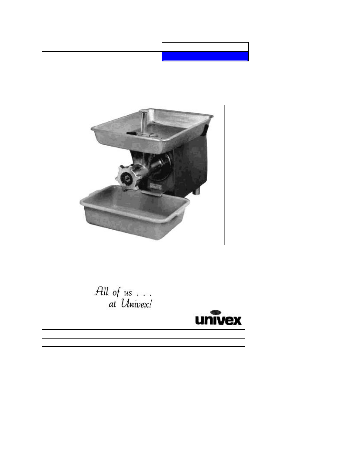
MEAT GRINDER
MG22
WE THANK YOU FOR YOUR PURCHASE OF OUR MODEL
MG22 MEAT GRINDER.
MG22/0199 ED1
Page 2

TABLE OF CONTENTS
Inspection:
on of options, and proper voltage However, upon unpacking, all items should be
•
in the throat or entry
designed to grind meat, use extreme caution and avoid exposing body parts to grinding
•
Always remove the grinder from the power drive before cleaning, never rinse with hose
DESCRIPTION PAGE
Table of Contents 1
Operator Safety 1
Installation 2
Assembly and Operating Instructions 2-3
Cleaning 3
Parts List 4-5
Assembly 6
Wiring Diagram 115/208-230 V, 60HZ, 1 PH / 220-240V, 50HZ, 1 PH 7
Wiring Diagram, Canada, CE, 115/208-240 V, 60HZ, 1PH / 230V.50HZ, 1PH 8
Warranty Information Back Cover
MG22 MEAT GRINDER
INSTRUCTION MANUAL
All Univex MG22's are inspected prior to packaging to assure both the machine quality,
correct inclusi
carefully verified that they are correct Any damage, imperfection, or shortages should be
reported immediately to your dealer or directly to Univex Customer Service, and/or shipment
carrier
Operator Safety:
Read and understand all instructions and safety warnings prior to operating unit
•
Never put fingers or any utensils (other than the stomper (Item 10)
of the grinder, or in the knife and plate area of the grinder This is a powerful unit
and cutting areas of the unit
•
Switch the power off and disconnect the electric power supply prior to mounting and
dismounting the grinder, cleaning, or servicing
Knife is sharp and can cut finger Use caution when handling
•
Always have chopper securely mounted, worm assembly fully coupled onto drive
coupling, and the knife, plate, and ring snugged on before switching the power on
•
while mounted to power source, inviting electrical shock
Page 1
Page 3

MG22
holes on the power drive housing bottom.
t
shaped feed hopper prevents accidental entry of operator's fingers and
Screw the ring
Never put fingers or utensils in the throat of the grinder or the knife and
Installation:
• This is a table-top unit. Unit may be secured to table top via the shipping bolt threaded
• Insure the unit is located such that it is placed on a level and stable surface, and sufficien
clearance is provided all around the unit for safety and ease of operation. Proper location
includes space for the feed pan and clip-on storage container.
• Feed pan support bracket (Item 45) must be assembled onto the housing cover (Item 43)
using the screws (Item 46) provided.
ASSEMBLY AND OPERATING INSTRUCTIONS:
Introduction:
The Univex MG22 Meat Grinder consists of a 1 H.P. electric motor power base which drives a
bell-shaped meat grinder designed to utilize industry standard #22 knives and full range of #22
grinding plates. Included as standard equipment is a carbon steel knife (Item 3), 3/16 grinding
plate (Item 2), aluminum meat stomper (Item 10), 16 x 24 aluminum feed pan (Item 9) for holding
meat to be processed, and 18.5 x 13.5 storage container with lid for collecting meat as it is
processed.
The Univex MG22 has safety and ease of operation built into it. The permanent safety guard
positioned over the bellhands into the grinding zone. The readily removable feed pan and storage container provide for
ease of processing and cleaning.
Noise emissions below 70 db (A).
Assembly:
WARNING: Disconnect power supply prior to assembly.
1. Mount the housing-guard assembly (Item 8) to the housing weldment (Item 26) by firmly
tightening knobs (Item 12) onto mounting studs (Item 14).
2. Slide the worm assembly (Items 6,5,4) into the housing-guard assembly (Item 8) and
mating into the drive coupling (Item 15).
3. Slide the knife (Item 3), sharp edges toward the plate, onto the square of the worm
assembly (Item 4). Slide the plate (Item 2) onto the worm assembly (Item 4).
(Item 1) onto the housing-guard assembly (Item 8) until it is just snug. Too much pressure
can damage the unit.
WARNING: The knife is sharp and can cut fingers.
4. Guide the feed pan (Item 9) over the guard portion of the housing-guard assembly (Item 8)
onto the pan stud (Item 7) and the pan support (Item 44).
5. Locate the storage container under the clip (Item 24) and resting on the front legs (Item 23).
6. Connect power supply and actuate power switch (Item 25).
WARNING:
plate interface.
Page 2
Page 4

Process:
Cut meat to be processed to fit under or through the safety guard. Recommended size
3.
wash, rinse, sanitize, and air dry. Use the bristle brush provided to clean areas difficult
1.
is 1 1/2" thick x 3" wide x 12" long. Set meat in pan (Item 9).
2. With grinder running, slide product under the guard of the housing-guard assembly
(Item 8) or through the openings in the guard top. Use the meat stomper (Item 10) if
desired, to guide product into grinding zone. The stomper is recommended for regrind.
Collect ground product in storage container.
Cleaning:
1. Turn unit off and disconnect from power supply.
2. Disassemble unit in reverse of assembly instructions — Remove storage container,
feed pan, and then ring, plate, knife, worm assembly, and housing-guard assembly.
WARNING: The knife is sharp and can cut fingers.
3. Clean components including the drive coupling (Item 15) by following the procedure:
to access. Apply a small amount of food grade lubricant to bronze bushing, located
inside the housing-guard assembly (Item 8), before use.
MG22
Page 3
Page 5

ASSEMBLY MG22
ILLUS.
PART NO.
DESCRIPTION
OTY. 1 1000719
RING,
#22 1
15 1000713
COUPLING, DRIVE
1
40 1814118 *
* LEG, REAR
2
42 7100107
STRAIN RELIEF
1
49
8700105
STORAGE CONTAINER (NOT SHOWN)
1
55
1000732
BRUSH, CLEANING (
NOT SHOWN)
1
57 8800229
WIRING PKG, (NOT SHOWN)
1 * ILLUS. NO.
7
IS INCLUDED WITH ILLUS. NO
8
2 1000727 PLATE, 3/16" 1
3 1000725 KNIFE, #22 1
4 1000715 SHAFT, FRONT 1
5 1000711 WORM, #22 1
6 1000717 COUPLING, WORM 1
7 1000731 * STUD, PAN 1
8 1000709 * HOUSING-GUARD ASSY 1
9 8700214 PAN 1
10 1000735 STOMPER 1
11 1000724 LOCK PIN, PLATE 1
12 8700222 KNOB 2
13 4400275 STUD - SWITCH ACTUATOR 1
14 1000718 STUD, MOUNTING 2
16 1200412 SET SCREW 1/4 - 20 X 1/4 CUP PT. 2
17 1200359 SCREW HEX. HD. SS CAP 3/8-16 X 1 1/2" LG. 6
18 1000722 WASHER, MOTOR 1
19 4400500 KEY 1/4 SQ. X 1 1/2 1
20 4400015 KEP NUT 3/8-16 8
21 8700219 GEAR MOTOR 1
22 8700220 SLEEVE, FRONT LEG 2
23 8700211 LEG, FRONT 2
24 8700216 CLIP, BUSS BOX 1
25 8700218 SWITCH, START/ STOP 1
26 8700210 HOUSING, WELDMENT 1
27 1200432 SCREW HEX. HD. CAP 4-40 X 3/4 LG. 2
28 7100103 SWITCH, SAFETY 1
29 7100023 INSULATOR, SAFETY SWITCH 1
30 1024414 BRACKET, SAFETY SWITCH 1
31 1200433 ELASTIC STOP NUT 4-40 2
32 1200076 WASHER 10 6
33 4400065 LOCK WASHER 10 6
34 1200060 HEX NUT 10-32 7
35 7510252 ELASTIC STOP NUT - M10 X 1.5 2
36 7100011 CONTACTOR 115V, 60HZ. 1
37 7100010 RAIL, DIN 1
38 4400155 SCREW HEX. HD. CAP 1/4-20 X 1/2 LG. 2
39 4400005 LOCK WASHER 1/4 2
1000726 PLATE 1/8' (OPTIONAL)
1000728 P LATE 1/4' (OPTIONAL)
1000729 PLATE 3/8' (OPTIONAL)
1000730 PLATE 1/2' (OPTIONAL)
7100015 CONTACTOR 100V, 50-60 HZ
7100012 CONTACTOR 230V, 60HZ
7100040 STARTER, 115V, 60HZ (CANADA ONLY)
7100116 STARTER, 230V, 60HZ, (CANADA ONLY)
7100108 STARTER, 230V, 50HZ, 1PH (EUROPE ONLY)
7100016 CONTACTOR, 220-240V, 50HZ,
41 8512855 FEET, REAR 2
43 8700212 COVER, HOUSING 1
44 8700215 SUPPORT, PAN 1
45 8700217 SLEEVE, PAN SUPPORT 2
46 4400246 SCREW, FLAT HD SLT SS 10-32 X 3/4 2
47 1200012 SCREW PPHD. 10-32 X 1/2 LG. 6
48 8700014 RUBBER STRIP
50 8800200 POWER CORD (NOT SHOWN) 1
51 8800208 CORD, MOTOR (NOT SHOWN) 1
52 4400326 LABEL, UNIVEX (NOT SHOWN) 1
53 4400351 LABEL, (NOT SHOWN) 1
54
56 4400401 CONNECTOR, 3/8 (NOT SHOWN) 1
** ILLUS. 40 INCLUDES STUD M10-1.5 X 22MM
RESERVED
Page 6

MG22
ASSEMBLY
Page 6
Page 7

WIRING DIAGRAM
WIRE TABLE
1
Before making electrical connections, check the specifications on the data plate
removed, DISCONNECT electrical cord and place a tag on it indicating the slicer is
115/208-230V, 60HZ, 1PH
220-240 V, 50HZ, 1PH
MG22
NOTES: 1
IMPORTANT:
WARNING:
PART
NUMBER
8800229
8800208 W8 MOTOR CORD
Whenever maintenance is being performed, or whenever the t op cover has been
being worked on.
WIRE
GA
NO.
W1 16 3 33 1
W2 16 3 13 1 2 WHITE
W3 16 3 2 1/2 1 1 RED
W4 16 3 24 1
W5 16 3 26 1 1 RED
W6 16 3 2 1/2 1 1 RED
W7 16 3 2 1/2 1 1 RED
DOUBLE CRIMP FERRULES. KLAUKE 72/1OVZ OR AMP 925553-2.
2.
MOLEX - ETC BB - 5623.
3. MATERIAL: 16GA 1015 TEW CSA AND UL APPROVED.
(located on the rear panel) to assure they agree with those of your electrical service.
SEE
NOTE
LENGTH
INCHES
Page7
IN
END A
SEE
NOTE
END B
SEE
COLOR
NOTE
2 WHITE
BLACK
Page 8

WIRING DIAGRAM
WIRE TABLE
1
1 1
1 1
1 1
1 1
1
1
NOTES
: 1
Before making electrical connections, check the specifications on the data plate
removed, DISCONNECT electrical cord and place a tag on it indicating the slicer is
CANADA & CE 115/208-240
V, 60HZ, 1PH 230V, 50HZ,
1PH
MG22
PART
NUMBER
8800229
PART OF
STARTER
8800208 W9 MOTOR CORD
IMPORTANT:
WARNING:
WIRE
2.
3.
Whenever maintenance is being performed, or whenever the top cover has been
being worked on.
GA
NO.
W1 16 3 33 1
W2 16 3 1 3
W3 16 3 2 1 /2
W4 16 3 24
W5 16 3 26
W6 16 3 2 1/2
W7 16 3 5 1/2 1
W8 16 3 8 1 /2 1
DOUBLE CRIMP FERRULES. KLAUKE 72 / 10VZ OR AMP 925553-2.
MOLEX-ETC BB-5623.
MATERIAL: 16GA 1015 TEW CSA AND UL APPROVED.
(located on the rear panel) to assure they agree with those of your electrical service.
SEE
NOTE
LENGTH
INCHES
END A
IN
NOTE
SEE
END B
SEE
NOTE
2 WHITE
2 WHITE
COLOR
RED
BLACK
RED
RED
RED
RED
Page 8
 Loading...