

Page 1
INSTRUCTION
MANUAL
G PEELER
tø
A
2'
«
F
Persons under age 18 are not permitted to operate or
have accessibility to operate this equipment per
U.S. Dept. of Labor Employment Standards
Administration Fact Sheet No. ESA91-3.
unuvex
GP/0904
PDF compression, OCR, web optimization using a watermarked evaluation copy of CVISION PDFCompressor
ED12
Page 2
G PEELER
TO INSURE BOTH SAFE AND
TROUBLE-FREE PERFORMANCE WE STRESS
THAT ALL PERSONNEL THAT WILL BE
INVOLVED WITH YOUR NEW UNIVEX G PEELER
MUST READ AND UNDERSTAND THESE
INSTRUCTIONS BEFORE, ATTEMPTING TO
OPERATE THIS UNIT.
WE APPRECIATE YOUR COOPERATION AND
YOUR BUSINESS. SHOULD THERE BE A
QUESTION OR IF WE CAN BE OF FURTHER
ASSISTANCE, PLEASE CALL US,
1-603-893-6191.
PDF compression, OCR, web optimization using a watermarked evaluation copy of CVISION PDFCompressor
Page 3
TABLE OF CONTENTS
G PEELER
DESCRIPTION
Table of Contents
Overall View of Peeler
Installation
Operating Instructions
Cleaning
Maintenance
Housing Assembly
Disk Drive Assembly
Motor Drive Assembly
Wiring Diagram 115V, 60HZ, 1PH
Wiring Diagram 220-230v, 50160HZ, 1PH
Wiring Diagram 115V, 60HZ, 1PH Canadian Specification Only
Wiring Diagram 220-240 V, 50HZ, 1PH British Specification Only
Warranty
PAGE
2
3
3
3
4
5
8
9
10
il
12
13
Back Cover
7
OPERATOR SAFETY
IT IS A VIOLATION OF UNITED STATES DEPARTMENT
REGULATIONS TO PERMIT OPERATION OF THE G-PEELER
PERSON UNDER THE AGE OF 18 YEARS.
READ AND MAKE SURE THAT YOU UNDERSTAND
SAFETY WARNINGS BEFORE ATTEMPTING TO OPERATE
NEVER PUT FINGERS OR HANDS IN PEELER WHILE
OPERATING OR SERIOUS INJURY COULD RESULT.
Page 1
PDF compression, OCR, web optimization using a watermarked evaluation copy of CVISION PDFCompressor
OF LABOR
BY ANY
INSTRUCTIONS AND
THE PEELER.
THE PEELER IS
Page 4

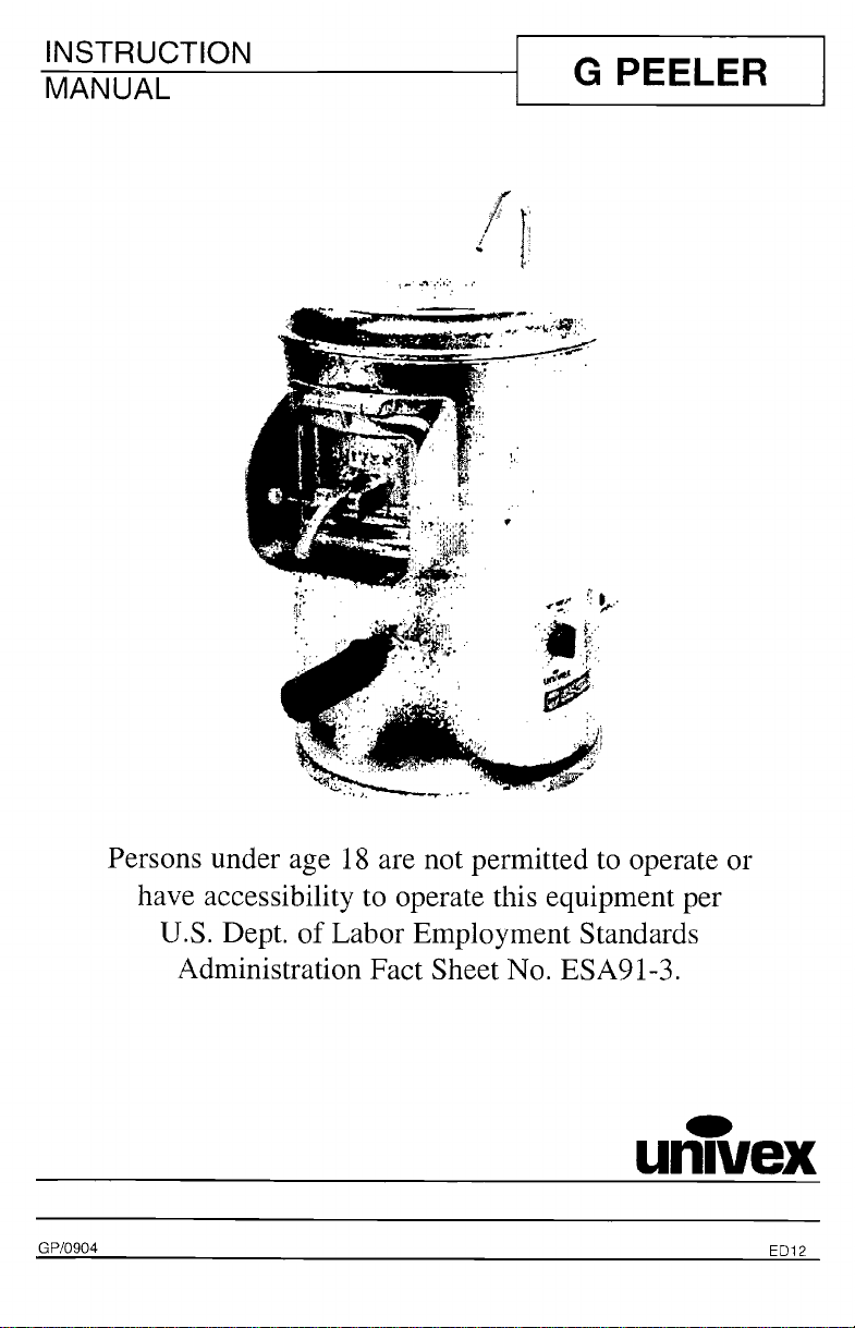
OVERALL VIEW OF PEELER
G PEELER
FIGURE 1
G PEELER
COVER 5- TIMER KNOB
WATER INLET TUBE
FLEXIBLE HOSE
6- DRAIN OUTLET
7- DISCHARGE DOOR
ELECTRICAL CORD
Page 2
PDF compression, OCR, web optimization using a watermarked evaluation copy of CVISION PDFCompressor
Page 5
G PEELER
JNSTALLATION
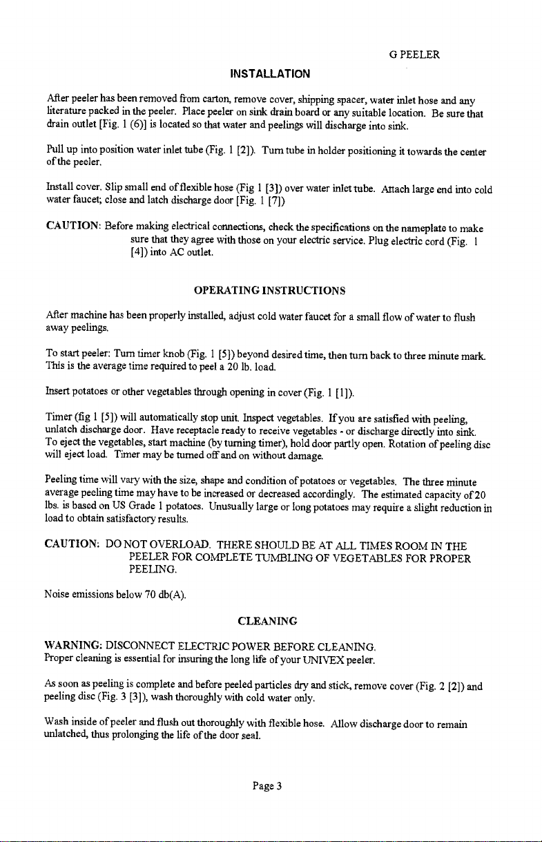
After peeler has been removed from carton, remove cover, shipping spacer, water inlet hose and any
literature packed in the peeler. Place peeler on sink drain board or any suitable location. Be
drain outlet [Fig. 1(6)1 is located so that water and peelings will discharge into sink.
sure that
Pull up into position water inlet tube (Fig. 1 [2]). Turn tube in holder positioning it towards the center
of the peeler.
Install cover. Slip small end of flexible hose (Fig 1 [3]) over water inlet tube. Attach large end into cold
water faucet; close and latch discharge door [Fig. 1 [7])
CAUTION: Before making electrical connections, check the specifications on the nameplate to make
sure that they agree with those on your electric service. Plug electric cord (Fig.
[4]) into AC outlet.
1
OPERATING INSTRUCTIONS
After machine has been properly installed, adjust cold water faucet for a small flow of water to flush
away peelings.
To start peeler: Turn timer knob (Fig. 1 [5]) beyond desired time, then turn back to three minute mark.
This is the average time required to peel a 20 lb. load.
Insert potatoes or other vegetables through opening in cover (Fig. 1 [1]).
Timer (fig 1 [5]) will automatically stop unit. Inspect vegetables. If you are satisfied with peeling,
unlatch discharge door. Have receptacle ready to receive vegetables - or discharge directly into sink.
To eject the vegetables, start machine (by turning timer), hold door partly open. Rotation of peeling disc
will eject load. Timer may be turned off and on without damage.
Peeling time will vary with the sìze, shape and condition of potatoes or vegetables. The three minute
average peeling time may have to be increased or decreased accordingly. The estimated capacity of 20
lbs. is based on US Grade i potatoes. Unusually large or long potatoes may require a slight reduction in
load to obtain satisfactory results.
CAUTION: DO NOT OVERLOAD. THERE SHOULD BE AT ALL TIMES ROOM IN THE
PEELER FOR COMPLETE TUMBLING OF VEGETABLES FOR PROPER
PEELING.
Noise emissions below 70 db(A).
CLEANING
WARNING: DISCONNECT ELECTRIC POWER BEFORE CLEANING.
Proper cleaning is essential for insuring the long life of your UNIVEX peeler.
As soon as peeling is complete and before peeled particles dry and stick, remove cover (Fig. 2 [2]) and
peeling disc (Fig. 3 [3]), wash thoroughly with cold water only.
Wash inside of peeler and flush out thoroughly with flexible hose. Allow discharge door to remain
unlatched, thus prolonging the life of the door seal.
Page 3
PDF compression, OCR, web optimization using a watermarked evaluation copy of CVISION PDFCompressor
Page 6

MAINTENANCE
G PEELER
WARNING: DISCONNECT THE ELECTRICAL POWER PRIOR TO PERFORMING ANY
MAINTENANCE
Maintenance is simple and has been kept to a minimum through modem engineering design.
To expose driving mechanism for service, lay unit on side and remove bottom cover (Fig. 2 [1 1]).
To replace belt, (Fig. 4 [3]) release tension spring (Fig. 4 [8]) to loosen belt. Hold motor in slack
position and roll belt off the large pulley. (Fig. 4 [5]) Reverse procedure to install new belt. Do not use
any metallic tools to force belt over pulleys. To do so will greatly shorten belt life.
Page 4
PDF compression, OCR, web optimization using a watermarked evaluation copy of CVISION PDFCompressor
Page 7

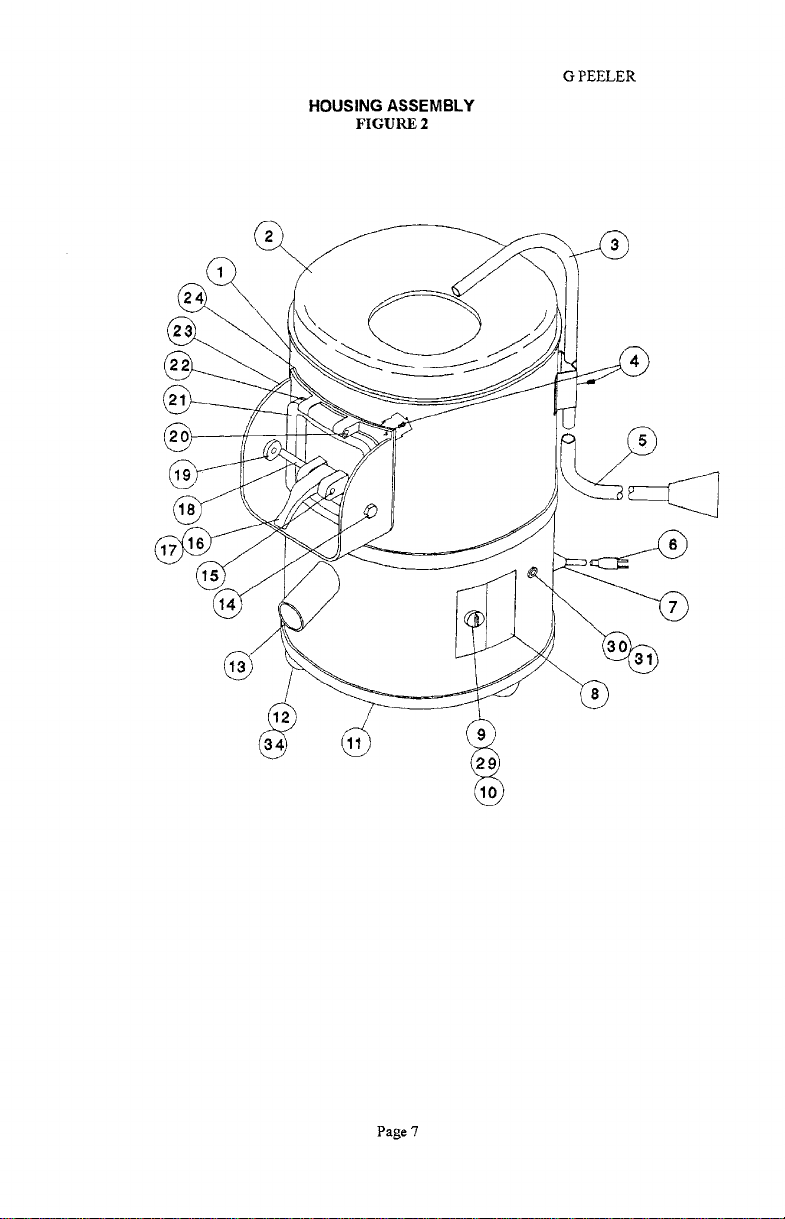
HOUSING ASSEMBLY
FIGURE 2
G PEELER
ILLUS. NO.
1
2
3
4
5
6
7
8
9
10
11
12
13
14
15
16
PART NO.
1120304
1120029
1120038
1200008
1120019
1120060
1120060.1
1120048
1120064
1120062
1120063
7100028
1120061
2300125
1120036
4400155
1120040
1120028
DESCRIPTION
HOUSING
COVER
TUBE, WATER INLET
SCREW, PPHD 8-32 X 3/8
HOSE, WATER INLET
CORD, ELECTRICAL, 115V, With Plug
CORD, ELECTRICAL, 220/230 V, Without Plug
STRAIN RELIEF, CORD
LABEL, TIMER
TIMER, 5 MIN., 1 POL, 115V
TIMER, 5 MIN., 2 POL, 220/230V
KNOB, TIMER
COVER, BOTTOM
FEET, RUBBER
HOSE, DRAIN
SCREW, HEX HD 1/4.20 X 1/2
PIN, DISCHARGE DOOR
HANDLE, DISCHARGE DOOR
QTY.
1
1
1
11
1
1
1
1
1
1
1
1
1
3
1
2
1
17
18
19
20
21
22
23
24
4400154
1120039
1120041
1120042
1120027
1120022
1120026
1120023
SET SCREW, HEX 10-32 X 1/4
BAR, LATCH
STOP, DOOR
PIN, HINGE
DOOR, DISCHARGE
SEAL, DISCHARGE DOOR
HOUSING, DISCHARGE
GASKET, HOUSING CHUTE
1
1
2
1
1
2FT
1
1
Page 5
PDF compression, OCR, web optimization using a watermarked evaluation copy of CVISION PDFCompressor
Page 8

HOUSING ASSEMBLY
FIGURE 2 (cont)
G PEELER
ILLUS. NO.
25
26
27
28
29 4400079
34
FOR CANADIAN SPECIFICATIONS ONLY
6
30
31
32
FOR BRITISH SPECIFICATIONS ONLY
6
7
30
PART NO.
DESCRIPTION
RESERVED
RESERVED
4400270
LABEL, WARNING (Not Shown)
RESERVED
SCREW M4-0.7 X 6MM LO (Not Shown)
1200465
1120060-2
4400238
SCREW, SS RD BD SLOTTED 1/4-20 X 5/8
CORD 115V, CSA ONLY
CIRCUIT BREAKER
4400227 LABEL, RESET
4400226
8800209
7100107
7100097
LABEL, CSA (not shown)
CORD 220-230, BRITISH ONLY
STRAIN RELIEF, CORD
CIRCUIT BREAKER
QTY
2
3
31
32
33
PDF compression, OCR, web optimization using a watermarked evaluation copy of CVISION PDFCompressor
4400227
4400423
4400335
LABEL, RESET
LABEL, CE (NOT SHOWN)
LABEL, GROUND (NOT SHOWN)
Page 6
Page 9
HOUSING ASSEMBLY
FIGURE 2
G PEELER
Page 7
PDF compression, OCR, web optimization using a watermarked evaluation copy of CVISION PDFCompressor
Page 10

ILLUS. NO.
1
2
3
4
5
6
7
8
9
10
ii
12
13
PART NO.
1120310
1120307
1120002
4400230
6509012
1030035
1200117
1030019
1120311
1120318
1200077
1200206
1120305
G PEELER
DISK DRIVE ASSEMBLY
FIGURE 3
DESCRIPTION
HOUSING, BEARING
DISC, DRIVE PEELING ASSY
DISC, DRIVE PEELING
KEYSQ3/16X1 1/2
SEAL, OIL
BEARING, BALL 5204ZZ
RETAINING RING, INT.
BEARING, BALL 6204LL
GASKET, BEARING HOUSING
RING, REINFORCEMENT
LOCKWASHER 5/16
SCREW, HEX HD SS 5/16.18 X 5/8
HOUSING, DIVIDER (PART OF ITEM 10F FIG. 2)
QTY.
1
1
1
1
1
3
1
1
1
4
4
2
Page 8
PDF compression, OCR, web optimization using a watermarked evaluation copy of CVISION PDFCompressor
Page 11

MOTOR DRIVE ASSEMBLY
FIGURE 4
G PEELER
1
2
3
4
5
6
7
8
9
10
11
12
13
14
1200412
1120302
1120303
1200119
1120302
1200036
1120047
1120017
2200021
1120316
4400083
6090012
1120225
1200060
SET SCREW 1/4-20 X 1/4
PULLEY, DRIVE
BELT, POLY-V
RETAINING RING, EXT.
PULLEY, DRIVEN
SET SCREW 5/16-24 X 3/8
TAB. BELT TENSION
SPRING, BELT TENSION
TAB, TENSION SPRING, 115V
BOLT, MPTOR MOUNT
NUTJAM3/8-24
MOTOR 1/3HP, 100-120V/200-240V, 50/60HZ, 1PH
ROD, MOTOR PIVOT
NUT, HEX HD 10-32
2
1
1
2
2
1
1
1
1
1
2
Page 9
PDF compression, OCR, web optimization using a watermarked evaluation copy of CVISION PDFCompressor
Page 12

WIRING DIAGRAM G-PEELER
115V, 60HZ, 1PH
FIGURE 5
GREEN
WHITE
BLACK
TIMER
G PEELER
POWER N
WHITE
BLACK
MOTOR
Page 10
PDF compression, OCR, web optimization using a watermarked evaluation copy of CVISION PDFCompressor
Page 13

WIRING DIAGRAM G-PEELER
220-230V, 50160HZ, 1PH
FIGURE 6
TIMER
GREEN
WHITE
BLACK
G PEELER
POWER IN
WHITE
BLACK
MOTOR
Page 11
PDF compression, OCR, web optimization using a watermarked evaluation copy of CVISION PDFCompressor
Page 14

WIRING DIAGRAM G-PEELER
FOR CANADIAN SPECIFICATIONS ONLY
i
r
115V, 60HZ, IPH
FIGURE 7
GREEN
WHITE
BLACK
TIMER
CIRCUIT BREAKER
G PEELER
POWER IN
J
L
WHITE
PDF compression, OCR, web optimization using a watermarked evaluation copy of CVISION PDFCompressor
BLACK
MOTOR
Page 12
Page 15

WIRING DIAGRAM G-PEELER
230V, 50HZ, 1PH
FOR BRITISH SPECIFICATIONS ONLY
FIGURE 8
OREEN
WHITE
i
CROUIT BREAKER
G PEELER
ROWER IN
Page 13
PDF compression, OCR, web optimization using a watermarked evaluation copy of CVISION PDFCompressor
 Loading...